1
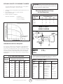
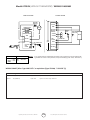
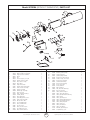
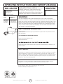
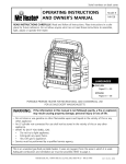
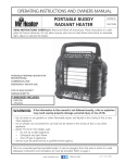
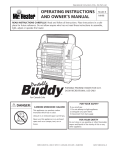
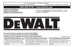
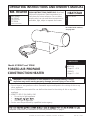
OPERATING INSTRUCTIONS AND OWNER’S MANUAL
MR. HEATER
(with thermostat)
TS170FAV
HEATSTAR
MODEL
MODEL
MH170FAVT
PA170FAVT
READ INSTRUCTIONS CAREFULLY: Read and
follow all instructions. Place instructions in a
safe place for future reference. Do not allow
anyone who has not read these instructions to
assemble, light, adjust or operate the heater.
HS170FAVT
(without thermostat)
For model serial numbers,
see page E10.
LANGUAGES
Model # 170FAVT and 170FAV
FORCED-AIR PROPANE
CONSTRUCTION HEATER
ENGLISH
Pages E1 — E10
FRENCH
Pages F1 — F10
WARNING: If the information in this manual is not followed exactly, a fire or
explosion may result causing property damage, personal injury or loss of life.
— Do not store or use gasoline or other flammable vapors and liquids in the vicinity of this or any
other appliance.
— An LP cylinder not connected for use shall not be stored in the vicinity of this or any other
appliance.
— WHAT TO DO IF YOU SMELL GAS
• Do not try to light appliance.
•
• Shut off gas to appliance.
— Service must be performed by a qualified service agency.
Adequate combustion and ventilation air must be provided. Refer to page 3.
MR. HEATER, INC., 4560 W. 160TH ST., CLEVELAND, OHIO 44135 • 216-916-3000
70176 Rev. F 04/10
WARNING: YOUR SAFETY IS IMPORTANT TO
WARNING: NOT FOR HOME OR RECREATIONAL
YOU AND TO OTHERS, SO PLEASE READ THESE
INSTRUCTIONS BEFORE YOU OPERATE THIS HEATER.
VEHICLE USE
WARNING:
FIRE, BURN, INHALATION, AND
EXPLOSION HAZARD. KEEP SOLID COMBUSTIBLES,
SUCH AS BUILDING MATERIALS, PAPER OR
CARDBOARD, A SAFE DISTANCE AWAY FROM THE
HEATER AS RECOMMENDED BY THE INSTRUCTIONS
NEVER USE THE HEATER IN SPACES WHICH DO
OR MAY CONTAIN VOLATILE OR AIRBORNE
COMBUSTIBLES, OR PRODUCTS SUCH AS GASOLINE,
SOLVENTS, PAINT THINNER, DUST PARTICLES OR
UNKNOWN CHEMICALS.
GENERAL HAZARD WARNING:
FAILURE TO COMPLY WITH THE PRECAUTIONS AND
INSTRUCTIONS PROVIDED WITH THIS HEATER, CAN
RESULT IN DEATH, SERIOUS BODILY INJURY AND
PROPERTY LOSS OR DAMAGE FROM HAZARDS OF
FIRE, EXPLOSION, BURN, ASPHYXIATION, CARBON
MONOXIDE POISONING, AND/OR ELECTRICAL SHOCK.
ONLY PERSONS WHO CAN UNDERSTAND AND FOLLOW
THE INSTRUCTIONS SHOULD USE OR SERVICE THIS
HEATER.
IF YOU NEED ASSISTANCE OR HEATER INFORMATION
SUCH AS AN INSTRUCTIONS MANUAL, LABELS, ETC.
CONTACT THE MANUFACTURER.
The State of California requires the following warning:
WARNING:COMBUSTION BY-PRODUCTS
PRODUCED WHEN USING THIS PRODUCT CONTAIN
CARBON MONOXIDE, A CHEMICAL KNOWN TO THE
STATE OF CALIFORNIA TO CAUSE CANCER AND BIRTH
DEFECTS (OR OTHER REPRODUCTIVE HARM).
SPECIFICATIONS
CONTENTS
MODEL NO..................................................... 170FAVT
Specifications.................................................................. E-2
GAS TYPE........................................................ Propane
Operating Precautions..................................................... E-3
BTU RATING............................125,000-170,000 BTU/hr
Safety Precations............................................................. E-3
(36.6 - 49.8 kW)
Odor Fade Warning........................................................ E-4
GAS SUPPLY PRESSURE TO REGULATOR ......................
Operating Instructions.................................................... E-4
.Maximum: Bottle Pressure, Minimum: 5 psig (34.5 kPa)
Storage & Service........................................................... E-5
Lighting Instructions....................................................... E-5
REGULATOR OUT.............................28” WC (6.97 kPa)
Wiring Diagram 170 FAVT............................................... E-6
ELECTRICAL INPUT.........................115V, 60 Hz, 1Ø, 3a
IGNITION....................... Direct Spark, interrupted type
Parts List 170 FAVT.......................................................... E-7
PRIMARY FLAME CONTROL.... SolidState,10-15 sec. timing
Exploded View Drawing 170 FAVT................................... E-7
HIGH TEMPERATURE CONTROL....................... 240°F (116°C)
Wiring Diagram 170 FAV (No Thermostat)....................... E-8
Parts List 170 FAV (No Thermostat).................................. E-9
Exploded View Drawing 170 FAV (No Thermostat)........... E-9
Minimum Ambient Temp. Rating: 0°F (-17.8°C)
FUEL CONSUMPTION........................... 5.8 - 7.9 lbs/hr
(2.6 - 3.6 kg/hr)
Fuel Orifice Port No.:
................... 18
Fuel Orifice Port Size:........................0.80mm favt
0.82 mm fav
Heated Air Output:.......... 450 CFM (12.74 cu m/m)
Operating Instructions and Owner’s Manual
E-2
Force-Air Propane Construction Heater
OPERATING PRECAUTIONS
SAFETY PRECAUTIONS
1.
This is a propane, direct-fired, forced air heater. It’s intended
use is primarily temporary heating of buildings under
construction, alteration or repair.
2.
3.
4.
Propane is heavier than air. If propane leaks from a
connection or fitting, it sinks to the floor, collecting there
with the surrounding air, forming a potentially explosive
mixture. Obviously, propane leaks should be avoided, so set
up the propane supply with utmost care. Read enclosed Odor
Fade and Propane Sheet for additional information about
detecting propane leaks. Leak check new connections or
reconnections with a soap and water solution and follow all
connection instructions herein. Also, ask your propane dealer
for advice on the propane application and supply installation
and ask him to check it if there are any questions.
5.
6.
7.
This heater was designed and certified for use as a
construction heater in accordance with ANSI Standard Z83.7/
CGA 2.14-2000. Check with your local fire safety authority
if you have any questions about your applications. Other
standards govern the use of fuel gases and heat producing
products in specific applications. Your local authority can
advise you about these.
8. 9.
10.
Direct-Fired means that all of the combustion products enter
the heated space. Even though this heater operates very close
to 100 percent combustion efficiency, it still produces small
amounts of carbon monoxide. Carbon monoxide (called CO)
is toxic. We can tolerate small amounts but not a lot. CO can
build up in a heated space and failure to provide adequate
ventilation could result in death.
11.
12.
13.
14.
15.
The symptoms of inadequate ventilation are:
• headache
• dizziness
• burning eyes and nose
• nausea
• dry mouth or sore throat
16.
17.
18.
So, be sure to follow advice about ventilation in these
operating instructions.
19.
Forced Air means that a blower or fan pushes the air through
the heater. Proper combustion depends upon this air flow;
therefore, the heater must not be revised, modified or
operated with parts removed or missing. Likewise, safety
systems must not be circumvented or modified in order to
operate the heater.
When the heater is to be operated in the presence
of other people the user is responsible for properly
acquainting those present with the safety precautions
and instructions, and of the hazards involved.
Figure 2: MINIMUM CLEARANCE: From normal combustible materials
Clearance
Forced Air 170FAVT
From floor........................................................0 ft
From outlet......................................................6 ft
From sides.......................................................2 ft
From top..........................................................3 ft
Figure 1
VENTILATION: Minimum openings required
Heater
Opening
near floor
Opening
near ceiling
Forced air (170 FAVT)
3 ft 3 ft
2
Locate 10 ft. from canvas or plastic tarpaulins or similar
coverings and secure them to prevent flapping or movement
due to wind action.
2
Force-Air Propane Construction Heater
Check the heater thoroughly for damage. DO NOT operate a
damaged heater.
DO NOT modify the heater or operate a heater which has been
modified from its original condition.
Use only propane gas.
Use only VAPOR WITHDRAWAL propane supply. If there is any
question about vapor withdrawal, ask your propane dealer.
Mount the propane cylinders vertically (shutoff valve up).
Secure them from falling or being knocked over and protect
them from damage.
Locate propane containers at least (USA) 7 ft. (2.13m),
(Canada) 10 ft. (3m) from the heater and do not direct exhaust
toward containers.
IMPORTANT Use only the hose and regulator assembly
provided with the heater. Match the color stripe on the
hangtag attached to the hose assembly with the color on
the label located near the propane inlet fitting on the heater.
Inspect hose assembly before each use of the heater. If there
is excessive abrasion or wear, or hose is cut, replace with hose
assembly listed on parts list before using heater.
For indoor use only. Area must be well ventilated. Figure 1.
(also see “Operating Precautions”).
If at any time gas odor is detected, IMMEDIATELY
DISCONTINUE operation until the source of gas has been
located and corrected. Read enclosed Odor fade and Propane
Sheet for additional information about detecting propane leaks.
Install the heater such that it is not directly exposed to water
spray, rain and/or dripping water.
Maintain minimum clearance from normal combustible material
(like paper). Figure 2.
Due to the high surface and exhaust temperatures, adults and
children must observe clearances to avoid burns or clothing
ignition.
Operate only on a stable, level surface.
Do not use with duct work. Do not restrict inlet or exit.
Use only the electrical power specified. The electrical
connection and grounding must comply with National Electrical
Code - ANSI/NFPA 70 (USA) and CSA C22.1 Canadian Electrical
Code, Part 1 (Canada).
Use only a properly grounded 3-prong receptacle or extension
cord.
Do not move, handle or service while hot or burning.
Do not adjust the heater combustion tube elevation while
heater is running or hot. Adjustments to elevation should only
be made after the heater has cooled to touch.
Use only in accordance with local codes or, in the absence of
local codes, with the Standard for the Storage and Handling
of Liquefied Petroleum Gases ANSI/NFPA 58 and CSA B149.1,
Natural Gas and Propane Installation Code.
E-3
Operating Instructions and Owner’s Manual
ODOR FADE WARNING
WARNING
Asphyxiation Hazard
•Do not use this heater for heating human living quarters.
•Do not use in unventilated areas.
•The flow of combustion and ventilation air must not be obstructed.
•Proper ventilation air must be provided to support the combustion air requirements of the heater being used.
•Refer to the specification section of the heater’s manual, heater dataplate, or contact the Factory to determine combustion air
ventilation requirements of the heater.
•Lack of proper ventilation air will lead to improper combustion.
•Improper combustion can lead to carbon monoxide poisoning leading to serious injury or death. Symptom of carbon monoxide
poisoning can include headaches dizziness and difficulty in breathing.
FUEL GAS ODOR
LP gas and natural gas have man‑made odorants added
specifically for detection of fuel gas leaks.
If a gas leak occurs you should be able to smell the fuel
gas. Since Propane (LP) is heavier than air you should
smell for the gas odor low to the floor. ANY GAS ODOR
IS YOUR SIGNAL TO GO INTO IMMEDIATE ACTION!
•
•
•
•
•
•
•
•
•
•
Do not take any action that could ignite the fuel gas. Do not operate any electrical switches. Do not pull any power
supply or extension cords. Do not light matches or any other
source of flame. Do not use your telephone.
Get everyone out of the building and away from the area
immediately.
Close all propane (LP) gas tank or cylinder fuel supply valves,
or the main fuel supply valve located at the meter if you use
natural gas.
Propane (LP) gas is heavier than air and may settle in low
areas. When you have reason to suspect a propane leak, keep
out of all low areas.
Use your neighbor’s phone and call your fuel gas supplier and
your fire department. Do not re‑enter the building or area.
Stay out of the building and away from the area until declared
safe by the firefighters and your fuel gas supplier.
FINALLY, let the fuel gas service person and the firefighters
check for escaped gas. Have them air out the building and
area before you return. Properly trained service people must
repair any leaks, check for further leakages, and then relight
the appliance for you.
colorless and the intensity of its odor can fade under
some circumstances.
If there is an underground leak, the movement of gas
through the soil can filter the odorant.
Propane (LP) gas odor may differ in intensity at different
levels. Since Propane (LP) gas is heavier than air, there may
be more odor at lower levels.
Always be sensitive to the slightest gas odor. If you
continue to detect any gas odor, no matter how small, treat
it as a serious leak. Immediately go into action as discussed
previously.
ATTENTION ‑ CRITICAL POINTS TO
REMEMBER!
•
•
•
•
Propane (LP) gas has a distinctive odor. Learn to
recognize these odors. (Reference Fuel Gas Odor and
Odor Fading sections above.
Even If you are not properly trained in the service and repair
of the heater, ALWAYS be consciously aware of the odors of
propane (LP) gas and natural gas.
If you have not been properly trained in repair and service
of propane (LP) gas then do not attempt to light heater,
perform service or repairs, or make any adjustments to the
heater on the propane (LP) gas fuel system.
A periodic sniff test around the heater or at the heater’s
joints; i.e. hose, connections, etc., is a good safety practice
under any conditions. If you smell even a small amount of
gas, CONTACT YOUR FUEL GAS SUPPLIER IMMEDIATELY. DO
NOT WAIT!
ODOR FADING ‑ NO ODOR DETECTED
•
•
•
•
Some people cannot smell well. Some people cannot smell
the odor of the man‑made chemical added to propane (LP) or
natural gas. You must determine if you can smell the odorant
in these fuel gases.
Learn to recognize the odor of propane (LP) gas and natural
gas. Local propane (LP) gas dealers will be more than happy
to give you a scratch and sniff pamphlet. Use it to become
familiar with the fuel gas odor.
Smoking can decrease your ability to smell. Being around
an odor for a period of time can affect your sensitivity to
that particular odor. Odors present in animal confinement
buildings can mask fuel gas odor.
The odorant in propane (LP) gas and natural gas is
Operating Instructions and Owner’s Manual
Heater Elevation Adjustment
This heater is equiped with an elevation adjustment panel
located at the exhaust end of the control box.
1. Do not adjust the heater combustion tube elevation while
heater is running or hot. Adjustments to elevation should
only be made after the heater has cooled to touch.
2. To adjust the heater combustion tube elevation, turn the
adjustment screw knob counterclockwise and lift the
combustion tube to desired position.
E-4
Force-Air Propane Construction Heater
OPERATING INSTRUCTIONS
MAINTENANCE AND STORAGE
1.
The heater should be inspected before each use, and at least
annually by a qualified person.
2. Before each use, check the soft “O” ring seat at the bullnose
of the POL fitting. If the “O” ring is cut, scuffed, or otherwise
damaged, replace it with part number 6681.
3. Turn off the gas at the LP-gas supply cylinder(s) when the
heater is not in use.
4. When the heater is to be stored indoors, the connection
between the LP-gas supply cylinder(s) and the heater must
be disconnected and the cylinder(s) removed from the heater
and stored out of doors and in accordance with Chapter 5 of
the standard for Storage and Handling of Liquefied Petroleum
Gases ANSI/NFPA 58 and CSA B149.1, Natural Gas and
Propane Installation Code.
PREPARING FOR OPERATION
1.
2.
3.
4.
5.
6.
7.
8.
Check the heater for possible shipping damage. If any is
found, immediately notify the factory.
Follow all of the “Precautions”.
Connect the POL fitting of hose and regulator assembly
to the propane cylinder by rotating the POL nut
counterclockwise into the propane cylinder’s valve outlet and
securely tighten with a wrench.
Connect the hose to the heater by rotating the hose fitting
clockwise.
Securely tighten all gas connections.
Open the cylinder’s gas valve and check all gas connections
with a soap and water solution. DO NOT USE A FLAME.
Connect power cord to well-grounded 115V, 60 Hz, 1Ø source
of power.
When using an extension cord, make certain that it is a
3-wire (grounded) cord of proper wire size.
SERVICING
170FAVT (WITH THERMOSTAT)
START
1.
Slowly open the main valve at propane cylinder to
prevent excess flow check valve from closing.
2. Set thermostat to full on. Heater will ignite
automatically.
3. Adjust ball valve on control panel to desired burn rate.
4. Set thermostat to desired temperature. Heater will turn
off and on automatically as the temperature varies in
the heater area.
The parts lists and wiring diagram show the heater as it was
constructed. Do not use a heater which is different from
that shown. In this regard, use only the hose, regulator and
cylinder connection fitting (called a POL fitting) supplied
with the heater. IMPORTANT Match the color stripe on the
hangtag attached to the hose assembly with the color on the
label located near the propane inlet fitting on the heater. Do
not use alternates. For this heater, the regulator must be set
as shown in “specifications”. If there is any uncertainty about
the regulator setting, have it checked.
STOP
1. Securely close valve on the propane cylinder.
2. Continue to operate heater until all fuel in the hose has
burned.
3. Turn the heater thermostat to “off”. For extended shut
down or in areas where the temperature is below 0°F,
unplug the heater.
170FAV (WITHOUT THERMOSTAT)
START
1.
2.
3.
4.
5.
6.
7.
A hazardous condition may result if a heater is used that has
been modified or is not functioning properly.
When the heater is working properly:
• The flame is contained within the heater.
• The flame is essentially blue with perhaps some
yellow tipping.
• There is no strong disagreeable odor, eye burning or other physical discomfort.
• There is no smoke or soot internal or external to the heater.
• There are no unplanned or unexplained shut downs
of the heater.
A heater which is not working right must be repaired, but
only by a trained, experienced service person.
Before heater ignition, always allow heater fan (blower)
to run for 20 seconds to purge fuel.
Slowly open the main valve at propane cylinder.
Depress the fuel valve button to light the heater.
After the heater lights, keep the gas valve button
depressed for 15 seconds then release and the heater
will continue to operate.
Adjust burn rate by setting control knob to desired level.
Igniter continues to fire as long as power cord is plugged
in.
a) Igniter sparks continually.
No thermostat usable with these units.
In-warranty products will be repaired with no charge for
either parts or labor. Please include a brief statement
indicating date, place of purchase, the nature of the problem
and proof of purchase.
Out-of-warrranty products will be repaired with a charge for
parts and labor.
STOP
1. Securely close valve on the propane cylinder.
2. Continue to operate heater until all fuel in the hose has
burned.
3. Unplug the power cord.
RESTART AFTER SAFETY SHUTDOWN
1. Securely close valve at propane cylinder. Unplug heater.
2. Wait 5 minutes.
3. Restart following “Start” procedure.
Force-Air Propane Construction Heater
E-5
Operating Instructions and Owner’s Manual
SIZE AND CAPACITY OF PROPANE CYLINDERS
WARNING: When using a thermostat controlled heater,
its exit area should be protected from personnel and
warnings posted of sudden startup.
The charts below show the approximate size of the cylinder
required for these heaters. To use the chart:
1. Select the lowest air temperature expected (at the bottom of
the chart).
2. Move straight up to time of operation desired
(left side of the chart).
3. Read the cylinder size required.
All heaters should have:
Recommended Minimum Gauge
for Cord Extensions
Wire Gauge Chart A.W.G.
Name
Plate 120V
Amps.
full cylinders
good air circulation
no frost on cylinders
25
5-6
6-8
8-12
10-12
12-14
Fuel Cyclinder Capacity: 100#
Cord Length in Feet
50
100
18
18
18
16
16
16
16
14
14
12
14
12
12
10
10
150
12
10
10
8
8
Model #170FAVT
wIRINg DIAgRAM
G
CHASSIS
GROUND
B
GAS
VALVE
SPARK PLUG
G
W
B
G
B
MOTOR
B
CHASSIS
GROUND
LINE
HIGH-LIMIT SWITCH X2
Y
VALVE
Y
CHASSIS
GROUND
W
THERMOSTAT
B
LINE CORD
G
HOW MUCH HEAT DO I REQUIRE?
W
GRD
G
CHASSIS
GROUND
For economy, it is important to match input to that required. But
heat requirements often vary. For example, it usually takes a lot
more heat to get things warm than it does to keep them that way.
Likewise, outside air temperature usually changes during the day
so you may need more heat at night than you do in the daytime.
An approximation of the heat required can be found by using the
chart below.
NEUT
R
R
FLAME CONTROL
CP MARK 10DN
CHASSIS
GROUND
COLOR CODE
B - BLACK
L - BLUE
G - GREEN
O - ORANGE
R -RED
W - WHITE
If any original wiring as supplied by the heater must be replaced,
it must be replaced with type AWG 105° C wire or its equivalent
except as indicated (*type SF2-200, **SGI 250° C).
BTU’S PER HOUR REQUIRED
Cubic feet
of space to
be heated
Temperature Rise Required (oF)*
20o
30o
40o
50o
5,000
14,000
20,000
27,999
34,000
7,000
19,000
28,000
38,000
47,000
10,000
27,000
40,000
54,000
67,000
15,000
40,000
60,000
80,000
100,000
20,000
54,000
80,000
30.000
80,000
50,000
133,000
170FAVT - WIRING CHART
107,000
133,000
120,000
160,000
200,000
200,000
266,000
333,000
COLOR
LENGTH
White
7”
Black
6”
Red-(Hi-Temp)
16 1/2”
Red-(Hi-Temp)
16 1/2”
Orange
11”
Green
7”
Red
7”
White
6”
Black
6”
Operating Instructions and Owner’s Manual
E-6
FROM
TO
Valve Terminal Block
On/Off Switch
Terminal Block
High Limit Switch
Valve
High Limit Switch
Terminal Block
Flame Control Spark Plug
(Ignition)
Flame Control
Ground
(Harness)
Flame Control Terminal Block
(Harness)
Flame Control
Terminal Block
(Harness)
Flame Control
Terminal Block
(Harness)
Force-Air Propane Construction Heater
Model #170FAVT (WITH THERMOSTAT) PARTS LIST
36
35
Item
Part No.
1 21732 1
21737 2 22249 3 22250 4 21146 5 26168 6 23038 7 27095 8 27094 9 26010 10 26074 11 22251 12 22252 13 26152 * 26152-20 14 26257 15 26433 16 26122 17 26101 18 28775 19 28777 20 28776 21 22253 22 28774 23 23037 Description
Qty.
Outer Shell - Model MH, HS
Outer Shell - Model PA
Middle Cylinder Orifice Assembly Flame Holder Assembly High Limit Switch Orifice Nut Handle
Handle Mounting Clips Set Screw, Nyloc Fan Motor Assembly Grille, Inlet/Motor Mounting Hose Assembly Hose Assembly, 20’ (HS only)
Regulator, 28” WC POL Excess Flow Valve Male Fitting Conn. 3/8MPT x 3/8SAE FLR
Solenoid Valve, Goyen Fitting Close Nipple Burn Rate Adjustment Valve Fitting, Elbow
3/8MPT x 1/2 SAE FLR Fuel Tube Assembly Spark Plug, Flame Sensor Spark Plug Nut Force-Air Propane Construction Heater
Item
1
1
1
1
1
1
1
1
2
1
1
1
1
1
1
1
1
1
Part No.
Description
24 24340 Thermostat Mounting Bracket 25 22254 Thermostat Assembly 26 26070 Loop Clamp, 5/16 27 27808 Flame Control, Potted 28 21036 Power Cord Assembly 29 28771 Terminal Board 30 26223 Bushing Strain Relief 31 28772 Knob, Thermostat 32 28773 Knob, Burn Rate Adjustment 33 22255 Control Box 34 22273 Base, Control Box 35 22274 Elevation Plate 36 22275 Elevation knob * 26375 Label, Elevation Adjustment * 28769 Label, Safety Precautions * 28755 Label, General Hazard Warning * 28733 Label, Model * 28731 Label, Operating Instructions * 26410 Label, Thermostate Warning * 27704 Label, Warning Massachusetts * 26374 Label, Warning Electrical * 27789 Label, Wiring Schmatic * 28203 Label, Hang Tag * 28679 Label, BTU 170,000 * 70176 Manual, Operating Instructions * 26225 Snap Bushing, 5/8 1
1
1
1
1
1
1
* Item not shown on exploded view
E-7
Operating Instructions and Owner’s Manual
Qty.
1
1
1
1
1
1
1
1
1
1
1
1
1
1
1
1
1
1
1
1
1
1
1
1
1
2
Model #170FAV (WITHOUT THERMOSTAT) WIRING DIAGRAM
WIRING DIAGRAMS
CONNECTION DIAGRAM
SCHEMATIC DIAGRAM
B
HIGH LIMIT
SWITCH X 2
VAC INPUT
MOTOR
TEMP
MOTOR
THERMOCOUPLE
B
HV TRANS
Y
Y
TO WIRE
B
MOTOR
VAC INPUT
HV TRANS
G
LINE CORD
GND
SCREW
B
115V
60HZ
SPARK PLUG
O**
GND
SCREW
HIGH LIMIT
SWITCH X2
MOTOR
TO WIRE
TEMP
W
SPARK
PLUG
IGNITION
CONTROL
TO WIRE
IGNITION CONTROL
TO JUNCTION
TEMP
MOTOR
G
VAC INPUT
W
COLOR CODE
B BLACK
W WHITE
G GREEN
LEGEND
R RED
Y YEL
O ORG
NOTE:
FEMALE CONN.
RING CONN.
If any original wiring as supplied with the heater, must be replaced, It must be replaced with
Type AWG 105° C wire or its equivalent, except as indicated (Type SF 2.200, **SGI-250° C)
WIRING CHART (Wire: Type AWG 150o C or equivalent (Type SF2-200, **SGI-250o C))
Color
Length
From
To
9ELLOW
MM
(IGH,IMIT
)GNITION#ONTROL4EMP4ERMINAL
9ELLOW
MM
(IGH,IMIT
)GNITION#ONTROL4EMP4ERMINAL
Operating Instructions and Owner’s Manual
E-8
Force-Air Propane Construction Heater
Model #170FAV (WITHOUT THERMOSTAT) PARTS LIST
REF. # ITEM # DESCRIPTION
1
2
3
4
5
6
7
8
9
10
11
12
13
14
15
16
17
20
21
22
23
24
25
26
27
28
29
21898
22252
21899
22251
26074
26655
23036
21900
23038
26168
21901
21146
21902
22249
21737
27095
27094
23037
28774
21903
28776
25027
28777
21905
27285
26127
21906
Motor Support Ring
Grill, Inlet/Motor Mounting
Support, Motor Stablizer
Motor Fan
Thermocouple, 10” w/JB
Bracket, Thermocouple
Nut, Thermocouple
Nut, Orifice
High Limit Switch
Bracket, High Limit Switch
Flame Holder Assembly
Orifice Assembly
Middle Cyl. Assembly
Outer Shell TS
Clips, Handle Mounting
Handle, Plastic
Nut, Spark Plug
Spark Plug/Flame Sensor
Flame Tube Assembly
Elbow, Flame Tube
Knob, Variable Rate
Valve, Variable Rate
Ftg. Connector
Valve, Thermoelectric
Ftg. Male Connector
Nut, TE Valve Retainer
Force-Air Propane Construction Heater
QTY.
1
1
1
1
1
1
1
1
1
2
1
1
1
1
1
2
1
1
1
1
1
1
1
1
1
1
1
E-9
REF. #
ITEM # DESCRIPTION
30
31
32
35
36
37
38
39
40
41
42
43
44
45
*
*
*
*
*
*
*
*
*
*
*
*
*
Bracket, ThermoValve Mt.
Bracket, Ignition/Relay
Spacer, Standoff
Ignition/Relay Module
Compression Block, Relay
Thermocouple, Connector
Control Box Assembly
Strain Relief Bushing
Power Cord Assembly
Cover, Cup, Valve
Knob, Elevation
Plate, Elevation
Nut, Elev. Plate Retaining
Base, Control Box
Label, Elevation Adjust.
Label, Safety Precautions
Label, General Hazard Warning
Label, Model
Label, Operating Inst.
Label, Warning Massachusetts
Label, Electrical Grounding
Label, Wiring Diagram
Label, Hang Tag
Label, Fan Rotation
Label, Fuel Button
Manual, Operating Inst.
Snap Bushings, 5/8”
21907
23045
26079
23276
26134
26656
21908
26223
21036
21912
25026
22274
21909
22273
26375
28769
28755
28733
28784
27704
26374
21910
28203
26373
27709
70176
26225
Operating Instructions and Owner’s Manual
QTY.
1
1
4
1
1
1
1
1
1
1
1
1
2
1
1
1
1
1
1
1
1
1
1
1
1
1
2
OPERATING INSTRUCTIONS AND OWNER’S MANUAL
MR. HEATER
(with thermostat)
TS170FAV
(without thermostat)
Model
MH170FAVT
HS170FAVT
PA170FAVT
Starting Serial
Number
LN-2701700001001
LN-1701700001001
LN-2220630001001
HEATSTAR
MODEL
MODEL
MH170FAVT
READ INSTRUCTIONS CAREFULLY: Read and
follow all instructions. Place instructions in a
safe place for future reference. Do not allow
anyone who has not read these instructions to
assemble, light, adjust or operate the heater.
HS170FAVT
WARNING:
USE ONLY MANUFACTURER’S REPLACEMENT PARTS. USE OF ANY OTHER PARTS
COULD CAUSE INJURY OR DEATH. REPLACEMENT PARTS ARE ONLY AVAILABLE DIRECT
FROM THE FACTORY AND MUST BE INSTALLED BY A QUALIFIED SERVICE AGENCY. MR.
HEATER HOSES F273701, F273702 AND F272702 ARE SPECIFICALLY DESIGNED FOR USE
WITH THIS HEATER ALONG WITH F273699 DISPOSABLE FUEL FILTER (REPLACE ANNUALLY) OR HOSE F273704 (FILTER NOT REQUIRED). USE OF OTHER HOSES MAY CAUSE
THE HEATER TO BECOME INOPERABLE.
PARTS ORDERING INFORMATION:
PURCHASING: Accessories may be purchased at any Mr. Heater local dealer or direct
from the factory
FOR INFORMATION REGARDING SERVICE
Please call Toll-Free 800-251-0001
www.mrheater.com
Please include the model number, date of purchase, and description of problem in all
communication.
LIMITED WARRANTY
Mr. Heater, Inc. warrants its heaters and accessories to be free from defects in material
and workmanship for a period of 1 year from date of purchase. Mr. Heater, Inc. will
repair or replace this product free of charge if it has been proven to be defective within
the 1-year period, and is returned at customer expense with proof of purchase to Mr.
Heater, Inc. within the warranty period.
Mr. Heater, Inc. reserves the right to make changes at any time, without notice or
obligation, in colors, speci¯cations, accessories, materials and models.
Mr. Heater GROUP, INC., 4560 W. 160TH ST., CLEVELAND, OHIO 44135 • 800-251-0001
Mr. Heater is a registered trademarks of Mr. Heater Group, Inc.
© 2009, Mr. Heater Group, Inc. All rights reserved
ANSI Z83.7a/CGA 2.14a-2007
Operating Instructions and Owner’s Manual
E-10
Force-Air Propane Construction Heater