1
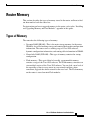
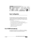
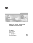
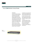
1
Cisco 1750 Router Overview
This chapter introduces the Cisco 1750 router, also referred to in this guide as “the
router,” and covers the following topics:
•
Key Features
•
Rear-Panel Ports and LEDs
•
Front-Panel LEDs
•
Router Memory
•
Unpacking the Router
•
Additional Required Equipment
Figure 1 shows the Cisco 1750 router.
Cisco 1750 Router Hardware Installation Guide
78-6169-02
i
Key Features
Cisco 1750 Router
17468
Figure 1
PWR
SLOT
PORT 0
0
SLOT
PORT 1
0
SLOT
PORT 2
0
OK
ETH
ACT
PORT
1
PORT
1
PORT
1
COL
Cisco
1700
SER
IES
RO UT
ER
Key Features
The Cisco 1750 router is a voice-and-data capable router that provides
Voice-over-IP functionality (VoIP) and can carry voice traffic (for example,
telephone calls and faxes) over an IP network. Using one to four WAN
connections, the router links small-to-medium-size remote Ethernet and
FastEthernet LANs to central offices. Table 1 lists the router key features.
Table 1
Key Features
Feature
Description
One FastEthernet (10/100BaseTX)
port
•
Operates in full- or half-duplex mode (with manual
override available).
•
Supports autosensing for 10- or 100-Mbps operation.
Cisco 1750 Router Hardware Installation Guide
ii
78-6169-02
Key Features
Table 1
Key Features (continued)
Feature
Cisco interface cards
Description
•
Supports two slots for either WAN interface cards (WICs)
or voice interface cards (VICs).
•
Supports one VIC-only slot.
•
Supports the following WICs: ISDN BRI (U and S/T), 56or 64-kbps DSU/CSU, FT1/T1 DSU/CSU, high-speed
serial, dual-serial, and 2Async/Sync.
•
Supports the following VICs: 2FXS, 2FXO, 2E&M.
•
Changes in WAN interface configuration can be made as
your network requirements change.
Console port
Supports router configuration and management from a
connected terminal or PC. Supports up to 115.2 kbps.
Auxiliary port
Supports modem connection to the router, which can be
configured and managed from a remote location. Supports up
to 115.2 kbps.
Security slot
Supports Kensington or similar lockdown equipment.
SNMP support
Supports Simple Network Management Protocol (SNMP) to
manage the router over a network.
AutoInstall support
Supports AutoInstall to download configuration files to the
router over a WAN connection.
Cisco ConfigMaker support
Supports Cisco ConfigMaker application, a wizards-based
software tool, to configure a network that includes the
Cisco 1750 router.
Cisco Voice Manager support
Supports Cisco Voice Manager to help you install and operate
voice and fax services over the IP network.
Compatible with Cisco Networked
Office stack
Stackable with other Cisco Networked Office stack products.
Cisco 1750 Router Hardware Installation Guide
78-6169-02
iii
Rear-Panel Ports and LEDs
Rear-Panel Ports and LEDs
This section describes the router rear-panel ports and LEDs, which are shown in
Figure 2 and described in Table 2 and Table 3.
Rear-Panel Components and LEDs
VIC
slot 2
Cisco 1750
SLOT 2
SLOT 1
VIC
2FXO
1 SEE MANUAL BEFORE INSTALLATION 0
Power switch
IN USE
Console port
IN USE
VIC
2FXS
IN USE
Kensington-compatible WIC/VIC
slot 1
locking socket
IN USE
Figure 2
1 SEE MANUAL BEFORE INSTALLATION 0
CONSOLE
THIS SLOT ACCEPTS ONLY VOICE INTERFACE CARDS
SLOT 1 OK SLOT 0 OK
Slot 1
OK LED
Slot 0
OK LED
FDX
100
WIC/VIC
slot 0
LINK
AUX
10/100 ETHERNET
10/100-Mbps
Ethernet port
Ground
wire
Auxiliary port
FDX/100/LINK LEDs
Table 2
PVDM OK
SLOT 2 OK
+5, +12, -12 VDC
PVDM
OK LED
17469
SLOT 0
Slot 2
OK LED
Power
socket
Rear-Panel Connectors
Connector/Slot
Label/Color
Description
Ethernet port
10/100-Mbps
ETHERNET
(yellow)
Router connection to the local Ethernet network. This
port autosenses the speed (10 or 100 Mbps) and duplex
mode (full or half) of the device to which it is connected
and then operates at the same speed and in the same
duplex mode.
Auxiliary port
AUX
(black)
Modem connection for remote configuration using
Cisco IOS software.
Console port
CONSOLE
(light blue)
Terminal or PC connection for local configuration using
Cisco IOS software.
Cisco 1750 Router Hardware Installation Guide
iv
78-6169-02
Rear-Panel Ports and LEDs
Table 2
Rear-Panel Connectors (continued)
Connector/Slot
Label/Color
Description
WIC/VIC slot
SLOT 0
Supports either a Cisco WIC or VIC. For detailed
information, refer to the Cisco WAN Interface Cards
Hardware Installation Guide that comes with every
card.
WIC/VIC slot
SLOT 1
Supports either a Cisco WIC or VIC. For detailed
information, refer to the Cisco WAN Interface Cards
Hardware Installation Guide that comes with every
card.
VIC slot
SLOT 2
Supports one Cisco VIC. For detailed information, refer
to the Cisco WAN Interface Cards Hardware
Installation Guide that comes with every card.
Power socket
+5, +12, –12
VDC
Router connection to the external power supply.
Protective earth
Ground wire
Router connection to earth ground by using a green and
yellow 14 AWG ground wire.
Use the rear-panel LEDs during router installation to confirm that you have
correctly connected all cables to the router.
Table 3
Rear Panel LEDs
LED Label
Color
Description
FDX
Green
On—Ethernet port is operating in full-duplex mode.
Off—Ethernet port is operating in half-duplex mode.
100
Green
On—Ethernet port is operating at 100 Mbps.
Off—Ethernet port is operating at 10 Mbps.
LINK
Green
On when the Ethernet link is up.
SLOT 0 OK
Green
On when either a WIC or VIC is correctly inserted in the
card slot.
SLOT 1 OK
Green
On when either a WIC or VIC is correctly inserted in the
card slot.
Cisco 1750 Router Hardware Installation Guide
78-6169-02
v
Front-Panel LEDs
Table 3
Rear Panel LEDs (continued)
LED Label
Color
Description
SLOT 2 OK
Green
On when a VIC is correctly inserted in the card slot.
PVDM OK
Green
On when a packet voice data module (PVDM) is
correctly inserted in the card slot.
Front-Panel LEDs
Use the router front-panel LEDs to determine network activity and status on the
Ethernet port and on the WIC and VIC ports. The front-panel LEDs are illustrated
in Figure 3 and described in Table 4.
Front-Panel LEDs
SLOT0 SLOT1 SLOT2
Table 4
PWR
PORT0
PORT0
PORT0
ETH
ACT
OK
PORT1
PORT1
PORT1
COL
17470
Figure 3
Front-Panel LEDs
LED
Color
Cards
Supported
LED Meaning
PWR
Green
–
On when DC power is being supplied to the router.
OK
Green
–
On when the router has successfully booted up and the
software is functional. This LED blinks during the
power-on self-test (POST).
Refer to the “OK LED Diagnostics” section in the
“Troubleshooting” chapter for information on how to use
this LED for router diagnostics.
ETH
Cisco 1750 Router Hardware Installation Guide
vi
78-6169-02
Front-Panel LEDs
Table 4
Front-Panel LEDs (continued)
Color
Cards
Supported
LED Meaning
ACT
Green
–
Blinks when there is network activity on the Ethernet port.
COL
Yellow
–
Blinks when there are packet collisions on the local
Ethernet network.
Green
ISDN
On when the first ISDN B channel is connected.
Serial and
CSU/DSU
Blinks when data is being sent to or received from the port.
LED
SLOTØ
PORTØ
2-port serial
VIC-2E&M
VIC-2FXO
VIC-2FXS
PORT1
–
Serial and
CSU/DSU
Off.
Green
ISDN
On when the first ISDN B channel is connected.
2-port serial
Blinks when data is being sent to or received from the port.
VIC-2E&M
VIC-2FXO
VIC-2FXS
Cisco 1750 Router Hardware Installation Guide
78-6169-02
vii
Front-Panel LEDs
Table 4
Front-Panel LEDs (continued)
LED
Color
Cards
Supported
LED Meaning
Green
ISDN
On when the first ISDN B channel is connected.
Serial and
CSU/DSU
Blinks when data is being sent to or received from the port.
SLOT1
PORTØ
2-port serial
VIC-2E&M
VIC-2FXO
VIC-2FXS
PORT1
–
Serial and
CSU/DSU
Off.
Green
ISDN
On when the first ISDN B channel is connected.
2-port serial
Blinks when data is being sent to or received from the port.
VIC-2E&M
VIC-2FXO
VIC-2FXS
SLOT2
PORTØ
Green
VIC-2E&M
Blinks when data is being sent to or received from the port.
VIC-2FXO
VIC-2FXS
PORT1
Green
VIC-2E&M
Blinks when data is being sent to or received from the port.
VIC-2FXO
VIC-2FXS
Cisco 1750 Router Hardware Installation Guide
viii
78-6169-02
Router Memory
Router Memory
This section describes the types of memory stored in the router and how to find
out how much of each the router has.
For instructions on how to upgrade memory in the router, refer to the “Installing
and Upgrading Memory and Data Modules” appendix in this guide.
Types of Memory
The router has the following types of memory:
•
Dynamic RAM (DRAM)—This is the main storage memory for the router.
DRAM is also called working storage and contains the dynamic configuration
information. The router stores a working copy of Cisco IOS software,
dynamic configuration information, and routing table information in DRAM.
•
Nonvolatile RAM (NVRAM)—This type of memory contains the startup
configuration.
•
Flash memory—This special kind of erasable, programmable memory
contains a copy of the Cisco IOS software. The Flash memory structure can
store multiple copies of the Cisco IOS software. You can load a new level of
the operating system in every router in your network and then, when
convenient, upgrade the whole network to the new level. The Flash memory
on the router is stored on mini-Flash modules.
Cisco 1750 Router Hardware Installation Guide
78-6169-02
ix
Router Memory
Amounts of Memory
Use the show version command to view the amount of DRAM, NVRAM, and
Flash memory stored in your router. The following example shows the output of
the show version command. The bold text displays the amount of memory stored
in this router.
1750# show version
Cisco Internetwork Operating System Software
IOS (tm) C1700 Software (C1700-SV3Y-M), Experimental Version
12.0(19980308:184442) [syaji-grammy-v6 189]
Copyright (c) 1986-1999 by cisco Systems, Inc.
Compiled Mon 22-Mar-99 12:58 by syaji
Image text-base: 0x80008088, data-base: 0x806B2BB8
ROM: System Bootstrap, Version 12.0(1)XA1,RELEASE SOFTWARE (fc1)
Router uptime is 15 minutes
System restarted by power-on
System image file is “flash:syaji/c1700-sv3y-mz”
cisco 1750 (MPC860) processor (revision 0x00) with 24576K/8192K bytes
of memory.
Processor board ID 0000 (1314672220), with hardware revision 0000
M860 processor: part number 0, mask 32
Bridging software.
X.25 software, Version 3.0.0.
1 FastEthernet/IEEE 802.3 interface(s)
2 Low-speed serial(sync/async) network interface(s)
2 Voice FXS interface(s)
2 Voice E & M interface(s)
32K bytes of non-volatile configuration memory.
8192K bytes of processor board System flash (Read/Write)
Configuration register is 0x0
Cisco 1750 Router Hardware Installation Guide
x
78-6169-02
Unpacking the Router
Unpacking the Router
Table 1-5 lists the items that come with your router. All these items are in the
accessory kit that is inside the box that your router came in.
Table 1-5
Router Box Contents
•
Power cord (black)
•
Power supply
•
DB-25 to DB-9 adapter
•
Console cable, RJ-45 to DB-9 (light blue)
•
Product documentation
Additional Required Equipment
Depending on your local network and which Cisco WICs and VICs you install in
your router, you might need other items listed in Table 6 to complete your router
installation.
Table 6
Additional Required Equipment
Equipment
When You Use It
Ethernet hub
A hub connects pieces of network equipment (including the router)
to create a network. You can use a 10-, 100-, or 10/100-Mbps hub
with the router.
Ethernet switch
A switch connects pieces of network equipment (including the
router) to create a network. You can use a 10-, 100-, or 10/100-Mbps
switch with the router.
Phillips screwdriver
Although the WICs and VICs use thumbscrews, you might need a
Phillips screwdriver to loosen the WIC and VIC cover.
Cisco WIC
To make a WAN connection, the router must have a supported WIC
installed. The router supports up to two cards. You can either order
the cards when ordering the router, and they will be installed for
you, or you can order the cards separately, after receiving the router,
and install them yourself.
Cisco 1750 Router Hardware Installation Guide
78-6169-02
xi
Additional Required Equipment
Table 6
Additional Required Equipment (continued)
Equipment
When You Use It
Cisco VIC
To make a voice connection, the router must have a supported VIC
installed. The router supports up to three cards. You can either order
the cards when ordering the router, and they will be installed for
you, or you can order the cards separately, after receiving the router,
and install them yourself.
Straight-through
RJ-45-to-RJ-45 cable
This cable connects the router to the Ethernet LAN and the WICs to
various WAN services, including ISDN, T1/FT1, and 56-kbps
services. You will need one cable for each of these connections.
Standard RJ-11 telephone
cable
This cable connects the VIC to a telephone, fax machine, or a
telephone wall-jack. You will need one cable for each of these
connections.
Standard RJ-48 telephone
cable
This cable connects the VIC to a PBX trunk line. You will need one
cable for each of these connections.
Serial cable
This cable connects a serial card to serial services. You must order
this cable from Cisco. For detailed information about serial cable
types, refer to the Cisco WAN Interface Cards Hardware
Installation Guide that comes with every card.
NT1
Some ISDN service providers require a Network Termination 1
device to connect an ISDN S/T port to the ISDN line.
Asynchronous modem
To configure the router from a remote location, connect a modem to
the AUX port on the router.
Cisco 1750 Router Hardware Installation Guide
xii
78-6169-02