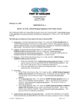
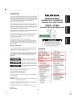
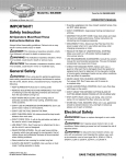
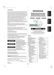
1
OWNER’S / OPERATOR’S
MANUAL
BROWN RIDE-ON
BLOWER-VAC
5/22/12
INTRODUCTION
CONGRATULATIONS! You are now the owner of a Brown RideOn Blower-Vac.
READ THIS MANUAL CAREFULLY! This manual will help you learn
how to operate and service your Brown Ride-On Blower-Vac
correctly. Failure to read and follow the instructions of this manual
could result in personal injury or equipment damage. This manual
should be considered a permanent part of your Brown Ride-On
Blower-Vac. All operators should read and follow these instructions
prior to operating the Brown Ride-On Blower-Vac.
TABLE OF CONTENTS
safety.............................................................................
1
operation.......................................................................
7
warranty......................................................................
13
service........................................................................... 16
parts list....................................................................... 18
ATTACHMENTS .................................................................. 28
All information, including illustrations and
specifications, contained in this manual are based
on the latest information available at the time of
publication. The right is reserved to make changes,
when deemed necessary, without notice.
PAGE LEFT BLANK INTENTIONALLY
PAGE 1
SAFETY
RECOGNIZE SAFETY INFORMATION
This is the safety-alert symbol. When you see
this symbol in this manual or on your Brown
Ride-On Blower-Vac, be alert to the potential
for personal injury.
UNDERSTAND SIGNAL WORDS
CAUTION is used for general reminders of
good safety practices
WARNING denotes a specific potential
hazard.
DANGER is the most serious specific
potential hazard.
These signal words are used in conjunction
with the safety-alert symbol.
FOLLOW SAFETY INSTRUCTIONS
Read owner/operator manual.
Replace missing or damaged safety decals.
Safety decals and this manual must be considered
a permanent part of your Brown Ride-On
Blower-Vac. Keep your Brown Ride-On BlowerVac in proper repair. Safety decals, manuals
and replacement parts are available through
your BROWN dealer. Unauthorized modifications
to the Brown Ride-On Blower-Vac are not
recommended. This could impair the function,
safety, and machine life. For any part of this
manual that you do not understand, contact your
BROWN dealer.
PAGE 2
SAFETY
WEAR PROTECTIVE CLOTHING
Wear close-fitting clothing appropriate for the job.
Wear a hearing protective device to protect from loud or
uncomfortable noise. Protective earmuffs provided with Brown
Ride-On Blower-Vac.
Wear proper eye protection. Safety goggles are supplied with each
Brown Ride-On Blower-Vac.
Wear appropriate foot wear.
PAGE 3
SAFETY
HANDLE FUEL SAFELY
Fuel is highly flammable. Handle with care.
Stop engine before refueling.
Do not refuel while smoking or near open flames.
Always fill fuel tank outdoors.
Keep machine clean of oil, grease, and dirt.
Clean up spilled fuel immediately.
Never store machine where fumes may reach flame or spark.
AVOID INJURY FROM THROWN OBJECTS
Before operating Brown Ride-On Blower-Vac:
Be sure all guards are in place.
Check operating area for dangerous obstacles
or uneven ground that may affect safe operation.
Clear area of people and pets.
PAGE 4
WARNING
SAFETY PRECAUTIONS
DO NOT operate Brown Ride-On Blower-Vac until thoroughly reading and
understanding this manual and becoming familiar with the operation of the
Brown Ride-On Blower-Vac.
DO NOT touch engine muffler or other hot surfaces.
DO NOT stand near blower discharge ports or adjust ports so that discharge
is aimed at people, animals or property that may be damaged by flying debris.
DO NOT operate the machine until area is cleared of people, pets, automobiles, etc. that might be damaged by projectiles.
DO NOT attempt to operate machine without all guards in place.
DO NOT allow a rider on Brown Ride-On Blower-Vac. Serious injury or
death may occur if anyone other than operator is on machine during operation.
Operator MUST WEAR eye and ear protection when operating the Brown
Ride-On Blower-Vac. (Eye goggles and hearing protection are provided
with each machine.)
Operator MUST WEAR appropriate footware and maintain both feet firmly
positioned on operator platform while operating machine.
Operation of a zero-turn-radius machine presents a serious risk of being
thrown from machine during certain maneuvers. Operator should slow down
during tight turns or while operating on uneven terrain, as well as maintain
a firm grip on operator handlebar at all times.
PAGE 5
SAFETY
TEST SAFETY SWITCHES
A. TEST PARKING BRAKE SAFETY SWITCH
1. Disengage parking brake
2. Turn key to start position
Result: Engine should not crank
B. TEST FAN HOUSING GUARD SAFETY SWITCH
1. Engage parking brake
2. Remove fan housing guard
3. Turn key to start position
Result: Engine should not crank
(re-secure fan housing guard after test)
C. TEST OPERATOR PLATFORM SAFETY SWITCH
1. Engage parking brake
2. Stand on operator platform
3. Turn key to start position and crank engine
4. Disengage parking brake
5. Place one foot on ground behind operator platform
6. Remove pressure from operator platform with remaining foot
Result: Engine should shut off
(re-engage parking brake after test)
NOTE: If parking brake is engaged, the engine will continue running when the operator steps off the operator platform. The engine
should only be allowed to run without operator on platform when
the operator is using truck loader attachment on even terrain.
PAGE 6
SAFETY
MACHINE SAFETY/PREPARATION
NOTICE: NEW ENGINES SHIPPED WITH MACHINES ARE GENERALLY
SERVICED PRIOR TO DELIVERY. HOWEVER, OPERATOR MUST
CHECK OIL AND ENSURE PROPER OIL LEVEL BEFORE STARTING.
WARNING: GASOLINE IS EXTREMELY FLAMMABLE AND
IS EXPLOSIVE UNDER CERTAIN CONDITIONS.
NOTE: FOR FURTHER INFORMATION CONCERNING THE SAFETY,
OPERATING, MAINTENANCE, ETC. OF THE PARTICULAR ENGINE
SUPPLIED WITH YOUR Brown Ride-On Blower-Vac, SEE THE
ENGINE OWNER’S MANUAL THAT IS SUPPLIED WITH THE
Brown Ride-On BLOWER-VAC.
BEFORE STARTING ENGINE
1. CHECK MACHINE
A. Read and be familiar with equipment operating instructions.
B. Wear eye and ear protection.
C. Ensure that all guards are secured in place.
D. Keep others away from machine.
2. CHECK ENGINE
A. Read and be familiar with manufacturer’s operating and safety
instructions for engine.
B. Check oil level and add if necessary. Do not over-fill.
C. Check air filter and clean frequently.
D. Use only clean fuel. Unleaded fuel is recommended in all engines.
E. Be sure muffler and exhaust deflector are installed, are in proper
position, and are in good operating condition.
3. CONNECT BATTERY CABLES TO BATTERY TERMINALS
PAGE 7
OPERATION
BROWN RIDE-ON BLOWER-VAC CONTROLS
PAGE 8
OPERATION
PARKING BRAKE OPERATION
Parking Brake Engaged / ON
Parking Brake Disengaged / OFF
PAGE 9
OPERATION
Engine Starting Procedure
A. Check Brown Ride-On Blower-Vac to ensure entire machine is clear of debris and all guards are in place.
B. Ensure airflow dampers are closed.
C. Engage parking brake.
D. Turn ignition to “ON” position.
E. Close choke if engine is cold.
F. Turn key to start engine.
G. As the engine warms, gradually move the choke back to the
open position
Using Hydrostatic Controls
Pushing a hydrostatic control lever forward will cause that lever’s corresponding
drive wheel to provide forward movement. The amount of input dictates the
speed of that wheel. The same applies when pulling the lever backward. This
will cause the corresponding drive wheel to provide backward movement with
the speed determined by the amount of input. A top-down drawing of the
hydrostatic controls is provided below.
PAGE 10
OPERATION
Controlling Hydrostatic Drive
This shows the neutral position. No input is being provided to either control.
This input will result in straight forward motion.
This input will result in straight backward motion.
This input will result in a left turn.
PAGE 11
OPERATION
Controlling Hydrostatic Drive
This input will result in a right turn.
This input will result in a stationary (ZTR) left turn on axis.
This input will result in a stationary (ZTR) right turn on axis.
PAGE 12
OPERATION
POSITIONING AIRFLOW DAMPERS
The Brown Ride-on Blower-Vac utilizes two independently controlled airflow
dampers in the air discharge port. This allows the operator to more fully control
the direction of airflow in order to accommodate varying conditions. The damper
control switches are located on the left side of the operator control panel. The
upper switch controls the forward damper and the lower switch controls the
rear damper. The image below illustrates this control interface.
Optimal positioning of Brown Ride-On Blower-Vac airflow dampers will
vary based on factors including: terrain; operator preference; nature of
material being moved; engine rpm; forward speed; and distance between
Brown Ride-On Blower-Vac and material being moved. Each operator will
need to experiment with different front and rear damper configurations in
order to achieve the most effective air pattern. The image below illustrates a
configuration that provides downward airflow from the front of the discharge
port and a more level airflow from the rear half of the port. A configuration
such as this may be beneficial for situations such as cleaning curbs, but optimal
positioning will vary per type of operation.
PAGE 13
WARRANTY STATEMENT
LIMITED WARRANTY
BROWN PRODUCTS INC. hereby warrants that the Brown Ride-On
Blower-Vac products will be free from defects in material and workmanship
under normal use according to the provisions and limitations herein set forth.
All parts, specifically EXCLUDING expendable “wear” parts, that become
unserviceable, due to defective material or workmanship, within one year / 12
months from date of the original retail purchase, shall, at Brown’s option, be
repaired or replaced.
LIMITATIONS
The obligations of Brown for breach of warranty shall be limited
to products manufactured by Brown; (1) that are installed, operated, and
maintained according to Brown’s instruction furnished and/or available to the
purchaser upon request; (2) that are installed according to all other applicable
Federal, State, and Local codes or regulations; and (3) that the purchaser
substantiates were defective in material and workmanship notwithstanding
that they were properly installed and correctly maintained as set forth and
were not abused or misused.
The obligation of Brown shall be limited to replacing or repairing the
defective product, at the option of Brown. Brown shall not be responsible for
any labor or cost of removal or repairing or re-installment of its products and
shall not be liable for transportation costs to and from its plant in Midland City,
Alabama.
Use of parts for modification or repair of the Brown Ride-On BlowerVac or any component part thereof not authorized or manufactured by Brown
specifically for the Brown Ride-On Blower-Vac shall void this warranty.
This warranty shall not apply to any damage to or caused by; (1) FORCE
MAJEURE, Act of God, or other accident not related to an inherent product
defect; or (2) abuse, misuse, or neglect of the Blower-Vac, including any
damage caused by improper assembly, installation, adjustment, or faulty
instruction of the purchaser.
Other than as expressly set forth hereinabove, Brown makes no other
warranty, express or implied, with respect to the Brown Ride-On BlowerVac, including but not limited to any merchantability or fitness for a particular
purpose.
In no event shall Brown be responsible for any incidental or consequential
damages of any nature suffered by purchaser or any other person or entity
caused in whole or in part by the Brown Ride-On Blower-Vac.
Any person or entity to whom this warranty extends and who claims
breach of warranty against Brown must bring suit thereon within one year
from the date of occurrence of such breach of warranty or be forever barred
from any and all legal or other remedies for such breach of warranty.
PAGE 14
Brown is not responsible for and hereby disclaims any undertaking,
representation, or warranty made by any dealer, distributor, or other person
that is inconsistent with or in any way more expansive than the provisions of
this limited warranty.
This warranty grants specific legal rights and shall be read in conformity
with applicable state law. In some jurisdictions, the applicable law mandates
warranty provisions that provide greater rights than those provided herein.
In such case, this limited warranty shall be read to include such mandated
provisions; and any provision herein that is prohibited or unenforceable in
any such jurisdiction shall, as to such jurisdiction, be ineffective to the extent
of such prohibition or un-enforceability without invalidating the remaining
provisions and without affecting the validity of enforceability of such provisions
in any other jurisdiction(s).
STATEMENT OF POLICY
In accordance with our established policy of constant improvement, we
reserve the right to amend these specifications at any time without notice.
ENGINE WARRANTY
Warranty of all engines and engine parts is the sole responsibility of
the particular engine manufacturer (Honda/Subaru). See engine warranty in
the engine manual provided with your purchase. Engine problems must be
checked and approved for warranty by an authorized engine manufacturer’s
service center. Brown Products Inc. is not an authorized service center for
any engine manufacturer and accepts no responsibility for engine warranties,
either expressed or implied. Contact the respective engine manufacturer for a
list of service centers near you.
TRANSAXLE WARRANTY
Warranty of all transaxles and transaxle parts is the sole responsibility of
the Hydro-gear. See transaxle warranty in the transaxle manual provided with
your purchase. Transaxle problems must be checked and approved for warranty
by an authorized transaxle manufacturer’s service center. Brown Products Inc.
is not an authorized service center for the transaxle manufacturer and accepts
no responsibility for transaxle warranties, either expressed or implied. Contact
Hydro-gear for a list of service centers near you.
WARRANTY BY MANUFACTURER
Dealer/distributor understands and agrees that the manufacturer
extends only the following warranty to its customers. In the event dealer/
distributor extends any additional warranty such as enlarging the scope or
period of warranty or undertaking a warranty of fitness for any particular
purpose or obligation not encompassed in manufacturer’s warranty, dealer/
distributor shall be solely responsible therefore and shall have no recourse
against manufacturer with respect thereto.
PAGE 15
WARRANTY REGISTRATION
Brown Ride-On Blower-Vac Warranty Card
Name ___________________________________ Model ________________________________
Address _________________________________
Serial Number _________________________
City/State _______________________________
Date Purchased ________________________
Phone __________________________________
Dealer ________________________________
E-Mail __________________________________
IMPORTANT: TO PLACE THE BROWN WARRANTY INTO EFFECT, THIS
WARRANTY CARD MUST BE COMPLETED AND MAILED WITHIN 30
DAYS AFTER RECEIVING THIS EQUIPMENT.
376 COUNTY ROAD 563
MIDLAND CITY, AL 36350
You may also register this product online by visiting:
http://brownproducts.com/products/warranty_registration.htm
PAGE LEFT BLANK INTENTIONALLY
PAGE 16
SERVICE
1. ENGINE SERVICE
A. See owner’s manual for service, maintenance requirements and procedures for engine.
2. TRANSAXLE SERVICE
A. See owner’s manual for service, maintenance require-
ments and procedures for transaxle.
3. BROWN RIDE-ON BLOWER-VAC SERVICE
A. Check all fasteners for proper tightness after each eight (8) hours of use or if vibration occurs. Loose hardware
may cause excessive vibration.
B. Check rear tire pressure before each use and ensure that each tire is filled to 14 PSI. Improper tire pressure could result in tipping hazard or inadequate
control of machine - especially on uneven terrain.
C. Check transaxle drive belt for wear. If necessary, replace.
D. Check belt tension and adjust if necessary.
E. Check fluid level in Hydro-Gear hydraulic fluid expansion
reservoir. Use only SAE 20W 50 motor oil.
Images showing location of expansion reservoir and drive
belt tensioner provided on following page
PAGE 17
SERVICE
LOCATION OF HYDRAULIC FLUID EXPANSION RESERVOIR
LOCATION OF DRIVE BELT TENSIONER
PAGE 18
PARTS
FRAME ASSEMBLY
PAGE 19
PARTS
DRIVE TRAIN
PAGE 20
PARTS
BLOWER
PAGE 21
PARTS
CONSOLE AND CONTROLS
PAGE 22
ITEM
NO.
1
N/S
2
N/S
3
4
N/S
5
6
7
8
9
10
11
12
13
14
15
16
17
18
N/S
N/S
N/S
N/S
N/S
N/S
N/S
19
20
21
22
23
24
25
26
N/S
27
28
29
30
31
32
33
BLOWER PARTS LIST: MODEL NUMBERS:
BVZ4000H & BVZ4000SD
QTY
1
2
1
3
1
4
4
1
1
4
1
2
2
1
1
1
1
1
1
1
1
2
2
2
2
8
2
8 OZ
1
1
1
1
1
1
1
1
1
1
2
1
1
1
1
1
PART NO.
350-035
350-012
350-306
260-786
350-036
SSB50C32
350-813
350-043
350-042
12-16
350-325
350-792
350-758
350-021
350-046
350-336
350-050
350-337
350-049
350-755
350-753
350-754
350-756
350-759
350-816
350-833
350-835
350-838
350-752
350-005
350-298
350-297
350-347
350-271
350-011
350-782
350-794
701-24A
260-783
260-782
WFE50Z20OD
350-252
350-777
350-812
DESCRIPTION
Frame
Strap, Frame Bottom
Kick Plate
Plunger Switch
Operator Platform
1/2" X 2" Shoulder Bolt
Spring, Operator Platform (Fits on Item #4 Shoulder Bolt)
Caster Wheel Tube, LH
Caster Wheel Tube, RH
Bearing W/Lock Collar
Battery Retaining Clamp
Torsion Fork, Swivel
Swivel Wheel, Front
Front Cross Tube
Counter Weight
Belt Guard, RH
Belt Guard Mount Bracket
Belt Guard, LH
Top Mount Drives Braclet
Transaxle Expansion Tank
Transaxle, LH
Breather Fitting, Transaxle
Fan-Pulley Kit, 4.5" Pulley, Transaxles
Drive Tire w/Wheel, Rear
Hose, Expansion, Transaxle
Nut, Lug, Wheel Attachment
Hose Barb, Breather, Transaxle
Oil, Transaxle, 20w-50
Transaxle, RH
Tie Rod, Transaxles
Neutral Lever, LH
Neutral Lever, RH
Vertical Bracket, Drive Mounts
Bottom Mount Bracket, Drives
Belt Idler Tensioner Bracket
Idler Tensioner Rod, Drive Belt
Belt, Drive
Spring, Belt Idler
Washer, Nylon
Bushing, Nylon
1/2" I.D. X 2" O.D. Fender Washer
Idler Arm, Drive Belt
Pulley, Idler, Drive Belt
Shaft, Auxiliary, Subaru
PAGE 23
BLOWER PARTS LIST: MODEL NUMBERS:
BVZ4000H & BVZ4000SD
ITEM
NO.
N/S
33
N/S
34
35
36
N/S
37
N/S
38
39
N/S
40
N/S
41
42
42
43
44
45
46
47
48
49
50
51
N/S
52
53
54
55
56
57
58
59
60
61
62
63
64
65
N/S
66
QTY
4
1
4
1
1
1
1
1
6
1
1
4
1
3
1
1
1
2
1
1
1
2
2
1
1
1
1
1
1
1
1
1
1
1
1
1
1
1
2
1
1
3
1
PART NO.
350-780
350-799
350-800
350-757
350-034
350-502
350-779
350-003
350-795
350-307
350-268
350-808
350-037
260-786
350-044
350-030
350-031
350-287
350-032
350-033
350-288
350-015
350-774
350-001
350-340
350-275
350-827
350-260
350-261
350-052
350-322
350-346
350-027
350-826
350-038
E-100-009
350-503
E-100-009
350-277
350-040
350-004
260-786
350-804
DESCRIPTION
Bolt, Auxiliary Shaft, Subaru
Shaft, Auxiliary, Honda GX690
Bolt, Auxiliary Shaft, Honda GX690
Pulley, Engine, 4in Dia, 1in Bore, A-Belt
Fan Housing
Fan Mount Hub/Flange
Key, Fan Hub/Flange
Fan
Bolt, Lug, Fan Attachment
Fan Retaining Washer
Cover Plate, Fan Housing, 12"
Spacer, Twist Lock (Fits on Item # 39 Cover Plate)
Switch Mount Bracket, Twist Lock
Plunger Switch (Mounts in Item # 40 Switch Mount Bracket)
12" Twist Lock w/Logo
Blower Flap, Front
Blower Flap, Rear
Indicator, Flap
Cover, Flap Actuator, Front
Cover, Flap Actuator, Rear
Actuator Cover, Top
Spacer, Flap Indicator Rod
Actuator, Flap, Fan Discharge
Fan Housing Mount Bracket
Heat Shield
Dash Panel
Decal, Dash Panel
Side Plate Upright, RH
Side Plate Upright, LH
Operator Cushion
Rear Closure Plate
Parking Brake Slotted Lever Bracket
Park Brake Pivot Bracket
Bushing, Parking Brake Lever
Lever, Parking Brake
Rod End
Parking Brake Linkage Rod
Rod End
Tire Lock Bracket, Adjustable
Tire Lock Bracket, LH
Brake Switch Tab
Plunger Switch (Mounts inside Item #53 Side Plate Upright, LH)
Shaft, Tire Brake
PAGE 24
BLOWER PARTS LIST: MODEL NUMBERS:
BVZ4000H & BVZ4000SD
ITEM
NO. QTY
67
1
68
1
N/S
2
N/S
2
N/S
1.5
N/S
2
N/S
2
69
1
70
1
70
1
N/S
2
N/S
2
N/S
1.5
N/S
2
71
1
72
2
73
2
74
2
75
2
76
1
77
4
78
1
N/S
4
79
1
N/S
4
80
1
81
1
82
1
83
1
83
1
N/S
1
N/S
1
N/S
1
N/S
1
N/S
1
N/S
1
N/S
1
N/S
2
N/S
2
N/S
1
N/S
1
N/S 1 or 2
N/S
1
PART NO.
350-039
350-761
350-762
350-772
350-768
350-769
350-770
350-048
350-825
350-765
350-766
350-767
350-771
350-773
350-294
780-03
350-760
350-828
350-790
350-020
350-776
350-009
350-791
350-029
350-791
350-028
350-326
350-327
350-262
350-334
260-770
350-836
260-776
350-814
260-777
350-815
350-751
350-775
350-789
350-834
350-839
350-840
350-841
DESCRIPTION
Tire Lock Bracket, RH
Fuel Tank, 5 Gal, CARB
Mount Strap, Fuel Tank
Clamp, Hose, Constant Tension 1/4"
Fuel Line, 3/16", CARB
Clamp, Hose, Constant Tension, 3/16
Hose, Fuel, 1/4", CARB
Fuel Tank Mount Bracket
Canister, Carbon, Subaru
Canister, Carbon 400, Honda
Carbon Canister Mounting Bracket
Carbon Canister Mounting Strap
Hose, Vent, 7/16
Clamp, Hose, Constant Tension 7/16"
Front Closure Plate
Ball Joint, Right hand Threads
Forward-Reverse Drive Control Rod
Ball Joint, Left Hand Threads
Damper, F-R Drive Control
Pivot Rod, Drive Controls
Bushing, Drive Lever Pivot
Drive Control Levers, RH
Grip, F-R Drive Control (Mounts on Item #78)
Drive Control Levers, LH
Grip, F-R Drive Control (Mounts on Item #79)
Rigid Tube, Drive Control
Reverse Stop, RH
Reverse Stop, LH
Cover, Control Module, Subaru
Cover, Control Module, Honda
Battery, 12VDC---PURCHASE LOCALLY
Decal, Battery Warning
Cable, Battery, Positive
Protector, Positive, Battery Terminal
Cable, Battery, Negative
Protector, Negative, Battery Terminal
Hearing Protection
Switch, Flap Control (Mounts in Item # 51 Dashboard)
Seal Boot, Flap Switch (Mounts on Part # 350-775)
Decal Sheet (See Decal Placement Drawing for locations)
Fuse Block (Mounts inside Item #52 Side Plate Upright, RH)
Relay (2 Required for Honda Engine & 1 for Subaru)
Diode (In wiring harness)
PAGE 25
BLOWER PARTS LIST: MODEL NUMBERS:
BVZ4000H & BVZ4000SD
ITEM
NO. QTY
N/S
1
N/S 50 OZ
N/S
1
N/S
1
N/S
2
N/S
1
N/S
1
N/S
1
N/S
1
N/S
1
N/S
1
N/S
1
N/S
1
N/S 50 OZ
N/S
1
N/S
1
N/S
1
N/S
1
N/S
2
PART NO.
350-817
350-837
260-769
350-781
350-803
350-807
350-810
350-832
350-811
350-824
350-829
350-778
350-798
350-837
260-812
350-796
350-797
350-801
350-802
DESCRIPTION
Engine, Subaru, EH72 W/Donaldson Air Cleaner (Purchase Locally)
Oil, Engine, 10W-30
Cable, Throttle, Subaru Only
Hour-Tach Meter, Subaru Only
Shim, Subaru Engine Mount
Cable, Choke, Subaru
Muffler, Subaru Engine
Clamp, Muffler, 1-1/4", SUBARU
Oil Drain, Extended Valve Kit, Subaru
Switch, Ignition, Subaru
Decal, Control Module, Subaru
Hose Barb, 90°, 1/4" Barb X 1/8 NPT-Donaldson AF
Engine, Honda GX690 (Purchase Locally)
Oil, Engine, 10W-30
Hose, Oil, Drain, Honda
Cable, Throttle, Honda GX690
Cable, Choke, Honda GX690
Muffler, Honda GX690
Shim, Honda Engine Mount
PAGE LEFT BLANK INTENTIONALLY
PAGE 26
DECAL PLACEMENT
PAGE 27
DECAL PLACEMENT
SAFETY DECAL PLACEMENT
ITEM
NO.
97
98
99
100
101
102
103
N/S
QTY
1
1
1
2
1
1
1
1
PART NO.
350-827
350-836
350-834
DESCRIPTION
Danger-Rotating Blade Hazard
Danger-Rotating Blade Hazard-Trilingual
Dashboard Decal
Warning-Moving Part Hazard-RH & LH
Warning-Eye Hazark
Danger-Thrown Object Hazard
Warning-No Step
Warning-Battery
Decal Sheet-Includes Item #'s 97, 98, 100, 101, 102, 103
PAGE 28
ATTACHMENTS
TRUCK-LOADER
PAGE 29
ATTACHMENTS
TRUCK LOADER ATTACHMENT
ITEM
NO.
91
N/S
N/S
QTY
1
1
2
PART NO.
353-001
350-821
350-823
92
93
94
N/S
N/S
95
N/S
N/S
1
1
1
1
2
1
2
2
353-003
353-004
353-005
350-820
350-822
353-006
FBB516C12Z
NFL516CZ
Suction Sleeve
10" X 12-1/2' Suction Hose
Hose Clamp, 10"
DESCRIPTION
Handle, Suction Hose
Intake Sleeve & Twist Lock, 10".
Discharge Square to Round
8" x 25' Discharge Hose
Hose Clamp, 8"
Discharge Truck Flange & Sleeve
BOLT, SERRATED FLANGE, 5/16" X 3/4"
NUT, SERRATED FLANGE, 5/16"
TRUCK LOADER ASSEMBLY INSTRUCTIONS
1. Attach Suction Hose Handle (Item# 92) to Suction Sleeve (Item# 91) using two 5/16” x 3/4” serrated flange bolts and two 5/16” serrated flange nuts.
2. Attach Suction Sleeve (Item# 91) to 10” x 12-1/2’ Suction Hose
using 10” Hose Clamp.
3. Attach Intake Sleeve and Twist Lock (Item# 93) to other end of
10” x 12-1/2’ Suction Hose using 10” Hose Clamp.
4. Attach Discharge Square-to-Round (Item# 94) to 8” x 25’
Discharge Hose using 8” Hose Clamp.
5. Attach Discharge Truck Flange and Sleeve (Item# 95) to other
end of 8” x 25’ Discharge Hose using 8” Hose Clamp.
PAGE 30
ATTACHMENTS
ATTACHING TRUCK-LOADER
DANGER: ENSURE THAT PARKING BRAKE IS ENGAGED
AND ENGINE IS SHUT DOWN BEFORE REMOVING FAN BLADE
GUARD AND INSTALLING TRUCK-LOADER ATTACHMENT.
1. Position Brown Ride-On Blower-Vac near area to be
vacuumed.
2. Engage parking brake.
3. Shut off engine.
4. Attach discharge hose coupler to discharge port of Brown
Ride-On Blower-Vac.
5. Attach clip to locking mechanism on discharge port to
ensure the discharge hose remains in place.
5. Attach Discharge Flange/Sleeve to truck bed or trailer.
6. Remove fan blade guard from front of machine by removing
clip and twisting guard assembly counter-clockwise.
7. Attach vacuum hose Intake Sleeve and Twist Lock to front
of fan blade housing by aligning holes on coupler with pegs
on housing and twisting clockwise to lock in place.
8. Attach clip to locking mechanism on coupler to ensure the
vacuum hose remains in place.
PAGE 31
ATTACHMENTS
BLOW-FORWARD
FORWARD BLOW ATTACHMENT
ITEM
NO.
96
QTY
1
PART NO.
352-002
Forward Blow Attachment
DESCRIPTION