1
FULLVIEW RECTANGLE DIRECT VENT GAS FIREPLACE HEATER
Model FV41
INSTALLATION INSTRUCTIONS MANUAL
DOCUMENT NO. FV41-IM-0610
Do not store or use gasoline or other flammable
vapors and liquids in the vicinity of this or any
other appliance.
WHAT TO DO IF YOU SMELL GAS
Open windows.
Do not touch electrical switches.
Do not try to light any appliance.
Extinguish any open flame.
Do not use the phone in your building.
Immediately call your gas supplier from a neighbor's
SKRQH)ROORZWKHJDVVXSSOLHU¶VLQVWUXFWLRQV
If you cannot reach your gas supplier, call the fire
department.
WARNING
If the information in this manual is not followed exactly, a
fire or explosion may result causing property damage,
personal injury or loss of life.
WARNING
Do NOT use this appliance if any part has been under water.
Immediately call a qualified service technician to inspect the
appliance and to replace any part of the control system and
any gas control, which has been under water.
In the Commonwealth of Massachusetts:
Installation must be performed by a licensed plumber or
gas fitter;
A CO detector shall be installed in the room where the
appliance is installed.
1|P age
WARNING: Improper installation, adjustment, alteration, service or maintenance can cause injury or property damage. Refer to this manual. For assistance or
additional information consult a qualified installer, service agency or the gas supplier.
FOR YOUR SAFETY
A qualified installer, service agency, or the gas supplier must perform installation and service.
Do not store or use gasoline or other flammable vapors and liquids in the vicinity of this or any other appliance.
WARNING
Do not operate this appliance with the glass removed,
cracked or broken. A licensed or qualified person
should do replacement of glass.
WARNING
Mendota gas fireplaces are heat producing appliances.
Do not burn wood, paper or other materials in this fireplace. This fireplace is designed as a supplement
heat source. It is advisable to have an alternative primary heat supply.
The installation must conform with local codes or, in
the absence of local codes, with the current National
Fuel Gas Code, ANSI Z223.1, or the current Natural
Gas and Propane Installation Code, CSA B149.1
CAUTION
THESE INSTRUCTIONS ARE TO REMAIN WITH
THE HOMEOWNER.
SAFETY AND WARNING INFORMATION
READ and UNDERSTAND all instructions carefully before starting the appliance. FAILURE TO FOLLOW these instructions may result in a possible fire hazard and will void the warranty.
Any safety screen or guard removed for servicing must be replaced before operating this appliance.
DO NOT USE this appliance if any part has been under water. Immediately CALL a qualified service technician to inspect
the appliance and to replace any part of the control system and any gas control, which has been underwater.
THIS UNIT IS NOT FOR USE WITH SOLID FUEL.
Installation and repair should be PERFORMED by a qualified service person. The appliance and venting system should
be INSPECTED before initial use and at least annually by a professional service person. More frequent cleaning may be
required due to excessive lint from carpeting, bedding, material, etc. It is IMPERATIVE WKDW WKH XQLW¶V FRQWURO FRPSDUtment, burners, and circulating air passageways ARE KEPT CLEAN to provide for adequate combustion and ventilation
air.
Always KEEP the appliance clear and free from combustible materials, gasoline, and other flammable vapors and liquids.
NEVER OBSTRUCT the flow of combustion and ventilation air. Keep the front of the appliance CLEAR of all obstacles
and materials for servicing and proper operation.
Due to high temperature, the appliance should be LOCATED out of traffic areas and away from furniture and draperies.
Clothing or flammable material SHOULD NOT BE PLACED on or near the appliance.
Children and adults should be ALERTED to the hazards of high surface temperature and should STAY AWAY to avoid
burns or clothing ignition. Young children should be CAREFULLY SUPERVISED when they are in the same room as the
appliance.
These units MUST use one of the vent systems described in the Installing Your Fireplace section of the Installers Guide.
NO OTHER vent systems or components MAY BE USED.
This gas fireplace and vent assembly MUST be vented directly to the outside and MUST NEVER be attached to a chimney serving a separate solid fuel-burning appliance. Each gas appliance MUST USE a separate vent system. Common
vent systems are PROHIBITED.
If the vent-air intake system is disassembled for any reason, reinstall per the instructions provided for the initial installation.
The vent system assembly for this fireplace must be periodically examined by a qualified service agency.
INSPECT the external vent cap on regular basis to make sure that no debris is interfering with the airflow. The flow of
combustion and ventilation air not to be obstructed
DO NOT abuse the glass door by striking the glass, slamming the door shut, etc.
Use only authorized parts and materials obtained from Johnson Gas Appliance Company when replacing defective or
damaged glass.
DO NOT USE abrasive cleaners on the glass door assembly. DO NOT ATTEMPT to clean the glass door when it is hot.
Turn off the gas before servicing this appliance. It is recommended that a qualified service technician perform an appliance check-up at the beginning of each heating season.
DO NOT place furniture or any other combustible household objects within 36 inches of the fireplace front.
2|P age
TABLE OF CONTENTS
SAFETY AND WARNING INFORMATION
SPECIFIC REQUIREMENTS FOR THE COMMON WEALTH OF MASSACHUSETTS
FV-41 FULL VIEW GAS FIREPLACE DIMENSIONS
TECHNICAL SPECIFICATIONS FOR FV-41
MINIMUM CLEARANCES TO COMBUSTIBLE CONSTRUCTION
MINIMUM COMBUSTIBLE ROUGH FRAMING DIMENSIONS
CONGRATULATIONS
BUILDING PERMIT AND INSTALLATION INSPECTION APPROVAL REQUIREMENTS
GENERAL APPLIANCE SPECIFICATIONS
MANTEL CLEARANCES
CLEARANCES TO COMBUSTIBLES FROM APPLIANCE SURFACES
PLANNING THE INSTALLATION
SELECTING APPLIANCE LOCATION
ROUGH FRAMING DIMENSIONS
CONSTRUCTING THE APPLIANCE CHASE
FRAMING DEPTH AND FINISHING GUIDES
FINISHING GUIDES
INNER GUIDE
OUTER GUIDE
FINISHING MATERIALS INSTALLATION
TILES AND FAUX ROCK
MARBLE AND GRANITE SLABS
HEARTH PROTECTION PAD REQUIREMENTS
GENERAL INFORMATION
SAFETY AND STRUCTURAL CONCERNS
VENTING REQUIREMENTS
HEATING PERFORMANCE
AESTHETIC CONSIDERATIONS
ELECTRICAL REQUIREMENTS
REMOTE CONTROL RECEIVER LOCATION AND MOUNTING REQUIREMENTS
GAS SUPPLY REQUIREMENTS
GAS SUPPLY LINE SIZING
GAS PRESSURE CHECKING REQUIREMENTS
GAS PRESSURE REQUIREMENTS
GENERAL INSTALLATION INSTRUCTIONS
HIGH ALTITUDE INSTALLATION INFORMATION
BLOWER OPERATION
OPERATION DURING POWER OUTAGES
BACKUP BATTERIES
GENERAL FLUE VENTING INSTRUCTIONS
COMPONENT "TWIST-LOCK" CONNECTION PROCEDURE
EXTERIOR VENT LOCATIONS AND RESTRICTIONS
FLUE VENTING COMPONENTS IDENTIFICATION
FV-41 MASTER FLUE VENTING REQUIREMENTS CHART
IMPORTANT VENTING CONFIGURATION NOTES
MAXIMUM HORIZONTAL RUN
MAXIMUM VENT SYSTEM LENGTH
HOW TO CALCULATE THE VENT SYSTEM LENGTHS
USING 900 (/%2:6,1=21(³%´
USING 900 (/%%2:6,1=21(³$´
USING 45-DEGREE ELBOWS
APPROVED VENT SYSTEMS
ZERO RISE HORIZONTAL TERMINATION
VERTICAL RISE HORIZONTAL TERMINATION
VERTICAL THROUGH-THE ROOF VENTING
0
VERTICAL THROUGH-THE-ROOF VENTING USING FOUR 90 ELBOWS
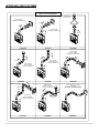
TO REMOVE DOOR
TO REPLACE DOOR
INSTALLATION CHECK OFF LIST
LIGHTING CHECK OFF LIST
BLOWER SYSTEM INFORMATION
3|P age
2
5
6
7
7
7
8
8
9
9
11
12
12
13
13
14
14
14
14
15
15
15
16
17
17
17
17
17
17
17
18
18
18
19
20
20
20
20
20
21
21
22
23
24
25
25
25
25
25
25
25
26
27
28
30
32
33
33
34
34
35
FLAME APPEARANCE ADJUSTMENT
FLAME APPEARANCE ADJUSTMENT- AIR SHUTTER ADJUSTMENTS
FLAME APPEARANCE ADJUSTMENT- EXHAUST DAMPER ADJUSTMENTS
TROUBLE SHOOTING THE FV-41 FIREPLACE & MAINTENANCE INFORMATION
OVER FIRING OF BURNER
MAINTAINING CORRECT PILOT-FLAME, PILOT OUTAGE & RELIGHTING
CLEANING VIEWING GLASS
SOOTING
OPERATION DURING POWER FAILURE
GAS SHUTOFF PROCEDURE
MAINTENANCE
NATURAL TO LP GAS CONVERSION
Read Before Attempting NG to LPG Conversion
ORIFICE SIZES REQUIREMENT:
LP PRESSURE REGULATOR CONVERSION INSTRUCTIONS
LP GAS PRESSURE REQUIREMENTS
LPG PROPER INPUT RATES:
LEAK TESTING REQUIREMENTS
PILOT FLAME AND MAIN BURNER RELATIONSHIP VERIFICATION
PILOT FLAME LENGTH ADJUSTMENT
CHECKING FOR NORMAL BURNER (S) IGNITION CHARACTERISTICS
ATTACHING LPG CONVERSION LABELS AND HIGH ALTITUDE DERATION LABEL
FV-41 VALVE ASSEMBLY REPLACEMENT PARTS
FV-41 GAS IGNITION SYSTEM WIRING DIAGRAM
GLASS FRAME ASSEMBLY REPAIR AND REPLACEMENT
TO REPLACE DAMAGED GLASS
LISTING LABEL INFORMATION
MENDOTA WARRANTY QUALIFICATION & SERVICE REFERENCE FORM
MENDOTA EXTENDED LIFETIME PROTECTION AND LIMITED WARRANTY
4|P age
36
36
36
37
37
37
37
37
37
37
38
39
49
39
40
42
42
42
42
42
43
43
44
45
46
46
47
48
51
Specific Requirements for the Common Wealth of Massachusetts
The information in this section applies to all installations performed in the Common Wealth of Massachusetts only.
a)
For all side wall horizontally vented gas fueled equipment installed in every dwelling, building or structure
used in whole or in part for residential purposes and where the side wall exhaust vent termination is less than
seven (7) feet above grade, the following requirements shall be satisfied:
1. If there is no carbon monoxide detector with an alarm already installed in compliance with the most current edition of NFPA 720, NFPA 70 and the Massachusetts State Building code in the residential unit
served by the side wall horizontally vented gas fueled equipment, a battery operated carbon monoxide
detector with an alarm shall be installed in compliance with the most current edition of NFPA 720. NFPA
70 and the Massachusetts State Building Code.
2. In addition to the above requirements, if there is not one already present, a carbon monoxide detector
with an alarm and a battery backup shall be installed and located in accordance with the installation requirements supplied with the detector on the floor level where the gas equipment is installed. The carbon
monoxide detector with an alarm shall comply with 527 CMR, ANSI/UL 2034 Standards or CSA 6.19 and
the most current edition of NFPA 720. In the event that the requirements of this subdivision cannot be
met at the time of the completion of the installation of the equipment, the installer shall have a period of
thirty (30) days to comply with this requirement; provided, however, that during said thirty (30) day period,
a battery operated carbon monoxide detector with an alarm shall be installed in compliance with the most
current edition of NFPA 720, NFPA 70 and the Massachusetts State Building Code. In the event that the
side wall horizontally vented gas fueled equipment is installed in a crawl space or an attic, the carbon
monoxide detector may be installed on the next adjacent habitable floor level. Such detector may be a
battery operated carbon monoxide detector with an alarm and shall be installed in compliance with the
most current edition of NFPA 720, NFPA 70 and the Massachusetts State Building Code.
3. A metal or plastic identification plate shall be permanently mounted to the exterior of the building at a minimum height of eight (8) feet above grade directly in line with the exhaust vent terminal for the horizontally
vented gas fueled heating appliance or equipment. The sign shall read, in print size no less than one-half
LQFKLQVL]H³*$69(17',5(&7/<%(/2:.((3&/($52)$//2%6758&7,216´
4. A final inspection by the state or local gas inspector of the side wall horizontally vented equipment shall
not be performed until proof is provided that the state or local electrical inspector having jurisdiction has
granted a permit for installation of carbon monoxide detectors and alarms as required above.
(b)
EXEMPTIONS: The following equipment is exempt from 248 CMR 5.08(2) (a) 1 through 4:
7KHHTXLSPHQWOLVWHGLQ&KDSWHUHQWLWOHG³(TXLSPHQW1RW5HTXLUHG7R%H9HQWHG´LQWKHPRVWFXUUHQW
edition of NFPA 54 as adopted by the Board; and
2. Product Approved side wall horizontally vented gas fueled equipment installed in a room or structure separate from the dwelling, building or structure used in whole or in part for residential purposes.
(c)
When the manufacturer of Product Approved side wall horizontally vented gas equipment provides a venting
system design or venting system components with the equipment, the instructions for installation of the
equipment and the venting system shall include:
1. A complete parts list for the venting system design or venting system; and
2. Detailed instructions for the installation of the venting system design or the venting system components.
(d) When the manufacturer of a Product Approved side wall horizontally vented gas fueled equipment does not
SURYLGHWKHSDUWVIRUYHQWLQJWKHIOXHJDVHVEXWLGHQWLILHV³VSHFLDOYHQWLQJV\VWHPV´WKHIROORZLQJVKDOOEHVatisfied:
7KHUHIHUHQFHG³VSHFLDOYHQWLQJV\VWHP´LQVWUXFWLRQVVKDOOEHLQFOXGHGZLWKWKHDSSOLDQFHRUHTXLSPHQWLnstallation instructions; and
7KH³VSHFLDOYHQWLQJV\VWHPV´VKDOOEH3URGXFW$SSURYHGE\WKH%RDUGDQGWKHLQVWUXFWLRQVIRUWKDWV\stem shall include a parts list and detailed installation instructions.
(e)
5|P age
A copy of all installation instructions for all Product Approved side wall horizontally vented gas fueled equipment, all venting instructions, all parts lists for venting instructions, and/or all venting design instructions shall
remain with the appliance or equipment at the completion of the installation.
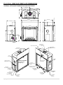
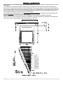
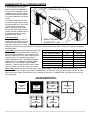
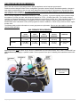
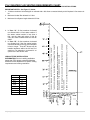
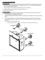
FV-41 FULL VIEW GAS FIREPLACE DIMENSIONS
OVERALL APPLIANCE DIMENSIONS AND FEATURES
20 9/16 in
19 5/8 in
19 3/16 in
9 1/16 in
10 1/8 in
19 3/16 in
40 3/8 in
19 3/16 in
39 1/4 in
8 1/16 in
8 1/16 in
19 5/8 in
6 3/8 in
35 in
43 1/16 in
36 3/16 in
4 7/8 in
13 13/16 in
23 15/16 in
43 1/16 in
32 1/2 in
4 7/8 in
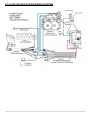
ACCENT LIGHT HOUSING
5"X8" COAXIAL
VENT STARTER
COLLAR
HEAT TRANSFER
DUCTS CONNECTION
PORTS
5"x8" COAXIAL
STARTER COLLAR
LH LIFT
HANDLE
LIFT
HANDLE
VISIBLE GLASS AREA
26-1/4" X 29-1/2"
[775 sq. in.]
CONTROLS ACCESS
& INSPECTION PLATE
Serial # and
Lighting Instructions
PlateS
STANDING PILOT
LIGHT SWITCH
GAS SUPPLY
INLET (1/2"MNPT)
FRONT BURNER
AIR SHUTTER
CONTROL
CONTROLS
HARNESSES
EXIT
GAS TRAIN,
IGNITION SYSTEM,
RH BLOWER
INSPECTION COVER
110VAC
INLET
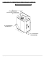
6|P age
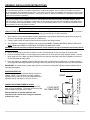
EXHAUST DAMPER
ADJUSTMENT
REAR BURNER
AIR SHUTTER
CONTROL
LH FRAMING
ATTACH
BRACKETS
RH BLOWER
INSPECTION
COVER
RH FRAMING
ATTACH
BRACKETS
TECHNICAL SPECIFICATIONS FOR FV-41
MODEL FV41
BTUH. (MODEL FV-41)
BTUH. (MODEL FV-41)
High Fire
- Adjustable to -
Low Fire
NAT. GAS
LP GAS
40,000
40,000
13,000
15,000
NOTE: LPG CONVERSION KIT, #New #, MUST BE PURCHASED SEPARATELY TO
CONVERT TO BURN LPG IN THIS FIREPLACE.
MAIN ORIFICE [0-2000ft (610 m)]: REAR BURNER: #42 NG [#54 L.P.] ± FRONT BURNER: #42 NG [#54 LP]
........................ [2000-4500ft (610-1370 m)]: REAR BURNER: #43 NG [#55 L.P.] ± FRONT BURNER: #43 NG [#55 LP]
OVERALL EFFICIENCY: ..................... EXCEEDS D.O.E. EFFICIENCY REQUIREMENTS (A.F.U.E.) FOR DIRECT VENT
WALL HEATERS.
CO-AXIAL DIRECT VENT FLUE: .......... 5" INNER, 8" OUTER
TOTAL WEIGHT: ................................... 225 POUNDS
SAFETY: ................................................ AGA/CECERTIFIED IPI AUTO ELECTRONIC IGNITION SYSTEM
ACTIVATED WITH THERMOSTATIC REMOTE CONTROL.
APPLIANCE CERTIFICATION AND TESTING AGENCY
INTERTEK TESTING SERVICES, ICBO#AA647-4
Certified under ANSI Z21.88 (2005) CSA 2-33 (2005³9HQWHG*DV)LUHSODFH+HDWHUVQRWIRUXVHZLWKVROLGIXHO$SSURYHGIRUEHdroom installations and mobile homes. UL307B approved for "mobile homes, after first sale of home, not for recreational vehicles."
GAS REQUIREMENTS .......................... SUPPLY PRESSURE:
GAS INLET: 1/2" N.P.T.
NAT. GAS:
7" W.C. (5" W.C. MIN., 11" W.C. MAX.)
L.P. GAS:
11.0" W.C. (11" W.C. MIN., 13" W.C. MAX.)
ELECTRICAL REQUIREMENTS ........... 115 VOLT, LESS THAN 1.5 amps (for blower operation only)
APPROVED VENT SYSTEMS............... DURAVENT, SELKIRK, AMERIVENT, SECURITY
MINIMUM CLEARANCES TO COMBUSTIBLE CONSTRUCTION
UNIT TO FLOOR
0in. (0mm)
UNIT TO ENCLOSURE SIDEWALL
1/2in. (13mm)
UNIT TO ENCLOSURE BACK WALL
1/2in. (13mm)
UNIT BOTTOM TO ENCLOSURE CEILING 48-1/2in. (123 cm)
UNIT BOTTOM TO ROOM CEILING
72 in. (1829 mm)
´0$17/($%29(',6&+$5*($,523(1,1*
18 in. (457 mm)
GLASS EDGE TO ADJACENT SIDEWALL
VENT PIPE TOP TO COMBUSTIBLES
VENT PIPE SIDES TO COMBUSTIBLES
VENT PIPE BOTTOM TO COMBUSTIBLES
18in. (457 mm)
2in. (51mm)
1in. (25mm)
1in. (25mm)
MINIMUM COMBUSTIBLE ROUGH FRAMING DIMENSIONS
WIDTH = 42-1/2´8cm)
HEIGHT = 47´(110cm)
DEPTH = 19-3/16´ (49cm)
THIS FIREPLACE INCLUDES A SEALED COMBUSTION SYSTEM, 8-PIECE CERAMIC FIBER LOG SET & COALS, FIREBRICK
LINED FIREBOX, NEO-CERAM GLASS, ELECTRONIC IGNITION SYSTEM, DUAL BLOWERS, AGA CERTIFIED SAFETY SYSTEM,
ACCENT LIGHT and THERMOSTATIC REMOTE CONTROL.
OPTIONS: BLACK, VINTAGE IRON, SWEDISH NICKEL, ANTIQUE GOLD, ANTIQUE COPPER HOMESTEAD & WILLOW DOORS,
DUCHESS STAINED GLASS FRONT, BOULEVARD DOORS, SERENADE AND PORTRAIT TRIMS and other accessories.
CAUTION
THESE INSTRUCTIONS ARE TO
REMAIN WITH THE HOMEOWNER.
This appliance may be installed in an
aftermarket, permanently located,
manufactured home (USA only) or
mobile home, where not prohibited
by local codes.
This appliance is only for use with
the type(s) of gas indicated on the
rating plate.
NOTE: This installation must conform to local codes. In the absence
of local codes, you must comply with the National Fuel Gas Code,
ANSI Z223.1-latest edition in the U.S.A. and the Natural Gas and
Propane Installation Code, CSA B149 Installation Codes in Canada.
WARNING: Do not operate this appliance with the glass removed,
cracked or broken. A licensed or qualified person should do replacement of glass.
HIGH ALTITUDE INSTALLATION INFORMATION: Prior to installing at altitudes higher than 7500, please contact the Mendota technical service department for specific venting requirements and venting restrictions.
7|P age
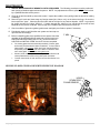
CONGRATULATIONS
You are the owner of a world-class heat producing gas direct vent sealed combustion fireplace.
This elegant, highly efficient Fireplace will be a constant source of comfort and fascination. It will be the focal point of
beauty and interest in your home.
The Mendota Gas Fireplace is a true heating appliance incorporating the traditional aesthetics of fireplace fire viewing with
the controllability and fuel efficiency of a home gas furnace. Of particular interest is the low fuel consumption and brilliant
fire viewing afforded by the realistic HearthGlo wood fire-like combustion system.
Carefully read the following instructions prior to actual installation. Proper Mendota Gas Fireplace installation and operation will give you years of safe, trouble free comfort and enjoyment.
If you have any questions regarding installation or operation of your Mendota Fireplace please contact your local dealer.
...CAUTION...
Due to high temperatures, the Fireplace should be located out of traffic and away from furniture and draperies. Children
and adults should be alerted to the hazards of high surface temperature and should stay away to avoid burns or clothing
ignition. Young children should be carefully supervised when they are in the same room as the Mendota Gas Fireplace.
Clothing or other flammable material should not be placed on or near the Fireplace.
Any safety screen or guard removed for servicing an appliance must be replaced prior to operating this appliance.
The Mendota Gas Fireplace is a powerful and efficient heating unit. It has been designed as a major source of supplemental heat. As with any mechanical appliance there can be component shut downs. It is advisable to have an alternate
heat supply.
Installation, repair and any adjustments to logs or burner must be done by a qualified service person. The appliance
should be inspected before use and at least annually by a professional service person. More frequent cleaning may be
required due to excessive lint from carpeting, bedding material, carbon build-up, etc. It is imperative that control compartments, burners and circulating air passageways of the appliance be kept clean. The burner and pilot flames and logs
should be visually checked periodically.
DO NOT use this appliance if any part has been under water or exposed to moisture corrosion. Immediately call a qualified service technician to inspect the Fireplace and replace any part of the control system and any gas control, which has
been under water. DO NOT use this fireplace if the burner does not light immediately. Turn unit off and call Mendota approved service person if there is any delay in burner light off.
It is Johnson Gas Appliance Company's policy that no responsibility is assumed by the Company or by any of its employees or representatives for any damages caused by an inoperable, inadequate, or unsafe condition which is the result,
either directly or indirectly, of any improper operation, installation or servicing procedures.
Building Permit and Installation Inspection Approval Requirements
All installations of Mendota Fireplaces and Inserts must comply with all the requirements stated in this Installation and
Operating Instructions Manual. The Dealer and/or installer must also obtain all required Building Permits and Inspection
Approval from the local building inspection department or the local body having jurisdiction. In order to validate warranty
coverage, Mendota may require facsimile copies of the Building Permit and Inspection Approval forms. Failure to provide
adequate proof that the installation conforms to all local requirements and the requirements stated in the Installation and
Operating Instructions Manual will void all applicable warranty.
INSTALLER: THESE INSTRUCTIONS ARE TO REMAIN WITH HOMEOWNER.
HIGH ALTITUDE INSTALLATION INFORMATION: Prior to installing at altitudes higher than 7500, please contact the Mendota technical service department for specific venting requirements and venting restrictions.
8|P age
FV41 DIRECT VENT GAS FIREPLACE
GENERAL APPLIANCE SPECIFICATIONS
HIGH ALTITUDE INSTALLATION INFORMATION: Prior to installing at altitudes higher than 7500, please contact the
Mendota technical service department for specific venting requirements and venting restrictions.
1" MIN.
422
ROUGH FRAMING WIDTH
35-1/2"
493
4"
9" TO VENT
PIPE CENTER
1"
328
11"
1716
19-1/2" MIN.
DEPTH
MINIMUM ROUGH FRAMING DIMENSIONS
HEIGHT
WIDTH
DEPTH
FROM UNIT BASE
TO ROOM CEILING
FROM UNIT BASE
TO 8" MANTEL
FROM UNIT BASE TO
UNIT ENCLOSURE CEILING
16"
TO GUIDE EDGE
11"
1716
47"
42-1/2"
19-1/2"
ADJACENT WALLS:
A wall perpendicular to and in front of this fireplace's
glass door surface must be at least 16 inches from the
side edges of the facing guide.
A wall at 45° to the glass surface and starting at this
Fireplace's outer edge is permitted. Projections behind
this wall (in shaded area) are permitted.
493
4"
5"
7016
72"
48"
50"
CEILING
24" MIN
TO VINYL SOFFIT
(18" MIN TO WOOD
OR METAL SOFFIT)
8" MANTEL DEPTH
AT HEIGHTS SHOWN
NON-COMBUSTIBLE ZONE
72" MIN.
TO
ROOM CEILING
47" MIN.
47
48" MIN.
UNIT BASE
TO 8" MANTEL
47" MIN.
ROUGH FRAMING
HEIGHT
347
8"
1" MIN
422
OPENING WIDTH
18"
8"
17"
79 "
781" 16
513"
16
11"
55"
7 16
7 " 48"
416
10"
9"
8"
7"
9"
316
31"
11" 8
216
4"
6"
5"
4"
2"
1"
0"
0"
13
3 116"
15 18"
1 16"
2"
241"
3"
FIREPLACE FACE MUST BE COVERED W/
NONCOMBUSTIBLE FACING IN THIS AREA.
A COMBUSTIBLE MANTEL ONLY ALLOWED IN
THIS AREA IF INSTALLED OVER
NON-COMBUSTIBLE FACING MATERIAL.
11"
616
12"
641"
HEIGHT ABOVE
CONVECTION AIR OPENING
15"
14"
13"
DISTANCE FROM
FIREPLACE FACE
9|P age
1" HEARTH PAD HEIGHT
12
(MIN R-1 RATING)
IS REQUIRED!
16"
1"
198
50" MIN.
UNIT FLOOR
TO ENCLOSURE
CEILING
42-1/2"
TO CENTERLINE
OF VENT CAP
18" min. Non-combustible Hearth
protection required [SEE HEARTH
PROTECTION PAD R-RATING, PAGE 12]
CAUTION: The distance from floor level to the centerline of the vent
cap is given based on Simpson Duravent GS components. If using
vent components of other brands do not assume that the
measurement given here is applicable. Verify the distance to
centerline of vencap by measuring the components you will be using.
NOTE: For every 1" this fireplace is raised off the floor,
the non-combustible hearth protection pad may be reduced
by 2". If this fireplace is raised off the floor more than 6",
No hearth protection pad is required.
NON COMBUSTIBLE FACING
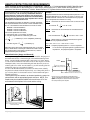
MANTEL CLEARANCES
Mantel Clearances for this fireplace may be measured from the top of the convection air opening or the floor level of
this fireplace.
The location that is referenced normally to measure mantel clearances is the Top of the Convection Air Opening. For
ease, however, measure up from the floor level of this fireplace. The chart and diagram, in this page, provide all the reference dimensional information necessary in determining the distance a combustible mantel may protrude out from the face
surface of this fireplace. The Chart, at right, shows the Distance from Fireplace Face the combustible mantel may protrude outward at a Distance up From Floor Level of this Fireplace.
If you prefer to take measurements from the Top of the Convection Air Opening, note that the Top of the convection air
opening is 30 inches up from the floor level of this fireplace.
WARNING: Make proper use of this chart. Do not compromise the specifications contained in this chart.
Failure to adhere to proper clearances required to combustibles may cause spontaneous combustion of the mantel and
may result in a fire causing property damage, personal injury or loss of life.
Figure 1: Mantel Clearances
FIREPLACE FACE MUST BE COVERED W/
NONCOMBUSTIBLE FACING IN THIS AREA.
A COMBUSTIBLE MANTEL ONLY ALLOWED IN
THIS AREA IF INSTALLED OVER
NON-COMBUSTIBLE FACING MATERIAL.
NON-COMBUSTIBLE ZONE
10 | P a g e
CLEARANCES TO COMBUSTIBLES FROM APPLIANCE SURFACES
Figure 2: Clearances to Combustibles
0" CLEARANCE
FROM TOP STANDOFFS
1/2" CLEARANCE
FROM BACK
1/2" CLEARANCE
FROM SIDES
11 | P a g e
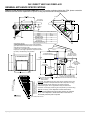
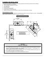
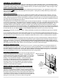
PLANNING THE INSTALLATION
When planning on appliance installation, it is necessary to determine the following information before installing:
Where the appliance is to be installed.
The vent system configuration to be used.
Gas supply piping.
Electrical Wiring.
Framing and finishing details.
Hearth Protection Pad Requirements.
Whether accessories such as a wall switch, remote control, and ceiling fan are desired.
Selecting Appliance Location
When selecting a location for your appliance, it is important to consider the required clearances to walls. See Error! Reference source not found. and Figure 2: Clearances to Combustibles.
Figure 3: Planning Installation
42-1/2 MIN.
ROUGH FRAMING
WIDTH
513
8"
19-1/2"
MIN.
1"
254
18"
173
4"
1"
192
42-1/2" MIN.
42-1/2 MIN.
ROUGH
FRAMING WIDTH
In addition to these dimensions, also reference:
Mantel Clearances Section
Framing Dimensions Section
Venting Configuration Section
353
8"
703
4"
WARNING
FIRE RISK- ODOR RISK
Install appliance on hard metal or wood surfaces extending full width and depth of this fireplace.
An R-1 Rated Hearth Protection Pad [1-´7KLFN0D[LPXP@LVUHTXLUHGXQOHVVWKLVILUHSODFHLVHOHYDWHG
)RUHYHU\´WKLVILUHSODFHLVHOHYDWHG\RXPD\UHGXFHWKHKHDUWKSDGGHSWKE\´,IWKLVILUHSODFHLVHOeYDWHG´RUKLJKHUQRKearth protection pad is required.
Do NOT install this fireplace directly on carpeting, vinyl or any combustible material other than wood. Construct chase to all clearance specifications in manual.
Locate and install appliance to all clearance specifications in manual.
12 | P a g e
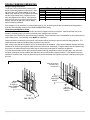
ROUGH FRAMING DIMENSIONS
Rough Framing Dimensions
The Rough Framing Dimensions must be maintained to allow this fireplace to slide into the fram0
ing cavity with a 90 elbow installed on the top
starter collar. After the FV-41 Fireplace is inserted
into the rough framed cavity, install one 2x4 on
HDFKVLGHDGMDFHQWWRWKHVLGHRIWKLVILUHSODFH¶V
body and one 2x4 on top of the top framing standoffs to close the air gap and to act as nailing
studs for finishing materials.
Minimum Rough Framing Dimensions
A
B
C
D
E
DESCRIPTION
Width
Height
Depth
Vent opening height
Vent opening width
DIMENSION (INCHES)
42-´
47´
19-1/2´ ´*UDQLWH0DUEOH)DFLQJ
10-´
10-´
If the fireplace is to be recessed in a cavity deeper than 19-´DOOIUDPLQJDQGILQLVKLQJPDWHULDOVSURWUXGLQJSDVWWKH
front face of this fireplace must be of the NON-COMBUSTIBLE variety.
Constructing the Appliance Chase
A chase is a vertical box-like structure built to enclose this fireplace and its vent system. Vertical vents that run on the
outside of a building may be, but are not required to be, installed inside a chase.
Construction of the chase may vary with the type of building. These instructions are not substitutes for the requirements of
local building codes. Local building codes MUST be adhered to.
Chases should be constructed in the manner of all outside walls of the home to prevent cold air drafting problems. The
chase should not break the outside building envelope in any manner.
Wall, ceiling, base plate and cantilever floor of the chase should be insulated. Vapor and air infiltration barriers should be
installed in the chase as per regional codes for the rest of the home. Additionally, in regions where cold air infiltration may
be an issue, the inside surfaces of the chase may be sheet rocked and taped for maximum air tightness.
To further prevent drafts, the fire stops should be caulked with high temperature caulk to seal the gaps. Gas line holes
and other openings should be caulked with high temp caulk or stuffed with unfaced insulation. If the appliance is being
installed on a cement slab, a layer of plywood may be placed underneath this fireplace to prevent conducting cold up into
the room.
Figure 4: FINALIZED Framing Dimensions
REMOTE RECEIVER
MOUNTING BOX
(2-GANG BOX)
43-3/16"
FINALIZED
HEIGHT
42-1/2"
FLOOR TO
WALL THIMBLE
CENTER
39-1/4"
FINALIZED
WIDTH
19-1/2"
MIN. DEPTH
13 | P a g e
FRAMING DEPTH and FINISHING GUIDES
The framing depth for this fireplace
is 19-1/2 inches. This is a fixed
depth required for all installations,
except a corner installation and for
installations that use solid Granite
or Marble slabs as fascia materials.
For corner installations, see figures
1 and 4.
OUTER FINISHING
GUIDES (TOP, L & R)
For installing solid Granite or Marble slabs as fascia material, reduce
WKHIUDPLQJGHSWKE\ò´WKHQLQVWDOO
ò´WKLFNGU\ZDOORQWKHIUDPLQJ
studs so that the drywall is flush
with the front face of this fireplace.
Install the Granite or Marble slab so
that it adheres to the face of the
fireplace and the drywall.
Finishing Guides
Two sets of Finishing Guides are
INNER FINISHING
supplied with this fireplace: One set
GUIDES(TOP, L &R)
is called the Outer Guide and the
other set is caOOHGWKH,QQHU*XLGH%RWKJXLGHVSURWUXGHRXW´IURPWKHIDFHRIWKLVILUHSODFH%RWKJXLGHVDUHIDFWRU\VeFXUHGXVLQJVFUHZVDQGPD\EHUHPRYHGLIQRWQHHGHGRUPD\EHSHUPDQHQWO\DWWDFKHGXVLQJ´ULYHWVWKDWDUHVXSSOLHG
with this fireplace.
Inner Guide: Identify the Inner Finishing Guides (Top,
Left and Right). These guides should be used as a
guide for finishing materials if you are planning to install WKLVILUHSODFHDVD³)8//9,(:´ZLWKRXWDQ\Gecorative front or if you are planning to install a
³%28/(9$5''225.,7´³'8&+(6667$,1('
*/$6629(5/$<´³32575$,7*/$66)5$0(
29(5/$<´or a ³6(5(1$'(*/$66)5$0(
29(5/$<´. Remove and discard the Outer Guides
(Top and sides) if you plan to use the Inner Guides.
DECORATIVE FRONT TYPE
FULL VIEW/ NO FRONT
BOULEVARD DOOR KIT
DUCHESS OVERLAY
SERENADE OVERLAY
PORTRAIT OVERLAY
WILLOW DOOR KIT
HOMESTEAD DOOR KIT
INNER GUIDE
USE
USE
USE
USE
USE
DISCARD
DISCARD
OUTER GUIDE
DISCARD
DISCARD
DISCARD
DISCARD
DISCARD
USE
USE
Outer Guide: Identify the Outer Finishing Guides (Top, Left and Right). These guides should be used as a guide for fiQLVKLQJPDWHULDOVLI\RXDUHSODQQLQJWRLQVWDOOD³+20(67($'´ or ³:,//2:´GRRUNLWRQWKLV fireplace. Remove and discard only the Inner Guides (Top and Sides only) if instalOLQJD³:,//2:´RU³+20(67($'´GRRUNLWDQG\RXSODQWRXVH
the Outer guides.
FV-41 DECORATIVE FRONTS
-FINISHING GUIDES SELECTION-
-SERENADEUSE
INNER GUIDE
-PIONEERUSE
INNER GUIDE
-HOMESTEADUSE
OUTER GUIDE
14 | P a g e
-DUCHESSUSE
INNER GUIDE
-WILLOWUSE
OUTER GUIDE
-BOULEVARDUSE
INNER GUIDE
FINISHING MATERIALS INSTALLATION
All finishing PDWHULDOVWKDWVXUURXQGWKLVILUHSODFH¶Vrectangle profile must extend out from the face surface of this fireplace
1 inch.
Tiles and Faux Rock
If installing Tiles or )DX[5RFNILUVWLQVWDOODò´WKLFN (minimum) Cement Board (Hardibacker or Durock Brand) over the
face of the fireplace and framing members. Follow by applying Thinset mortar (no polymer additives) XVLQJó´VTXDUH
notched trowel on the cement board surface. Finally, install tile to reach a finish material depth of 1 inch.
Marble and Granite Slabs
If installing Marble or Granite slabs as fascia materials, specify that the inner edges that will be adjacent to the Glass Door
DUHSROLVKHG5RXJK)UDPLQJVKRXOGEHFUHDWHGDW´GHSWKZLWKWKHIURQWVXUIDFHRIWKLVILUHSODFHSURWUXGLQJRXWò´IURP
WKHIUDPLQJVXUIDFH,QVWDOO
´WKLFNGU\ZDOl on framing members so that its outer surface is flush with the front face of
this fireplace. Attach Marble or Granite slabs to face of unit and to drywall surface using adhesive that does not offgas
when hot.
,QWKHDUHDGHILQHGDV³121&20%867,%/(=21(´ [FIGURE 7], only NONCOMBUSTIBLE MATERIALS ARE
ALLOWED.
When this fireplace is installed in a framed cavity that is 19-1/2´GHHSWKHIDFLQJPDWHULDOILQLVKLQJJXLGHZLOOSUotrude out into the room 1 inch. Build finishing materials to 1 inch thickness and use the built-in guides for edge
alignment of fascia material. &RQVXOWVHFWLRQ³)5$0,1*'(37+DQG),1,6+,1**8,'(6´
DETAIL B
SCALE 0.26 : 1
1.00 INCH
FACE OF
FV-41
1" FINISHING
GUIDE
WARNING: See Figure 7. The cross hatched areas labeled as
³121&20%867,%/(=21(´PXVWEHFRYHUHGZLWKQRncombustible finishing materials that is 1-inch thick, minimum. DO
NOT ALLOW COMBUSTIBLE MATERIALS TO ENCROACH IN
THIS AREA!
Figure 6:
NON COMBUSTIBLE ZONE [ALL HATCHED AREAS]
15 | P a g e
NON-COMBUSTIBLE ZONE
[ALL HATCHED AREAS]
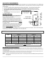
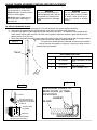
HEARTH PROTECTION PAD REQUIREMENTS
Hearth Protection R Rating: MINIMUM R-,65(48,5('86(2)$ò´7+,&.0,1,080&(0(17BOARD (HardiEDFNHU:RQGHUERDUGRURWKHUEUDQGSOXVó´WKLFNPRUWDU7KLQ6HWW\SHSOXVó´WKLFNFHUDPLFWLOHH[FHHGWKH5-1 reTXLUHPHQW8VHWKLVDVDUHIHUHQFHLILQGRXEW1DWXUDO6WRQHVRI´RUJUHDWHUWKLFNQHVVDOVRH[FHHG5-1 rating.
All hearth pads must be non-combustible (metal, brick, stone, or
mineral fiberboard). Do not use any combustible material to
protect the floor in front of this fireplace. For the FV-41, the
hearth protection pad must be rated at R-1 minimum AND it
must extend 18 inches in front of the fireplace face if the FV41 fireplace is installed at floor level.
Use the following procedure to determine if a hearth pad meets
the requirements listed in this manual. Find the available values,
R, K or C and follow the formulae below to arrive at a R value.
R-value = Thermal Resistance
K-value = Thermal Conductivity
C-value = Thermal Conductance
Convert the specification to R-value;
a. If R-value is given, no conversion is needed.
b. If K-value is given with for a thickness (t) in inches:
1
T ...( 1 divided by K , then multiplied by thickness).
K
1
c. If C-value is given: R
«GLYLGHGE\&
C
R
Determine the R-value of the proposed hearth pad. For multiple
layers, add R-values of each layer to determine overall R-value. If
the overall R-value of the system is greater than R-1, then the
proposed hearth pad is acceptable.
Example:
Required minimum R value for hearth protection pad is R=1. The
SURSRVHGDOWHUQDWLYHLV´WLOHZLWKD&- facWRURIRYHU´
mineral board with a K-factor of 0.29. Determine if the proposed
layers will provide the minimum R=1 rating.
Step A. Use formula to convert C-IDFWRURIWKHó´WLOHWR5-value.
R of the tile:
R of mineral board:
= 1/1.25 = 0.80
R
1
T
K
=1/0.29 x 0.125 = 0.431
Step C. $GG5YDOXHVRIó´7LOHDQGPLQHUDOERDUGWRJHWWKH
Total R-value of proposed alternative:
RTotal = Rtile + Rmineral board = 0.8 + 0.431 = 1.231.
Step D. Compare proposed system R = 1.231 to required R
of 1.0. Since R of proposed system is greater than the
required R=1, the proposed system is acceptable.
Figure 7:
16 | P a g e
1
C
Step B. Use formula to convert K-factor of mineral board to Rvalue.
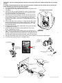
Hearth Pad Guide- [Usage and Removal]
This fireplace is shipped with a Hearth Pad Guide Installed. The purpose of
the Hearth Pad Guide is to limit the height of the Hearth Pad during installations. DO NOT build a Hearthpad that is more than 1-´WKLFN'RLQJ
so will not allow installation of decorative fronts on this fireplace. After the
Hearthpad is built, remove the Hearth Pad guide and discard if you do not
wish the guide to be visible. In some instances, you will want the guide left
permanently, based on your aesthetic judgment.
To remove the Hearth Pad Guide, first remove the Glass Frame. Identify
the plastic Rivet heads inside the fireplace body. Use a sharp utility knife to
pry or cut the plastic rivet head and rivet base. Lift the Hearth Pad Spacer
upwards and remove.
This fireplace may be installed in an elevated position by created an
elevated deck and an appropriate framed enclosure. NOTE: This
ILUHSODFHPD\EHHOHYDWHGEXW0867DOORZDPLQLPXPRI´GLsWDQFHEHWZHHQWKLVILUHSODFH¶VIORRUOHYHODQGWKHFHLOLQJ
PRY or CUT RIVET HEAD USING A SHARP EDGE.
REPEAT FOR 4 RIVETS.
R
FRONT
1" MAX. THICK HEARTH PAD
12
(MIN R-1 RATING) IS REQUIRED!
FIGURE 8
18" min. Non-combustible Hearth
protection required [SEE HEARTH
PROTECTION PAD R-RATING, PAGE 12]
NOTE: For every 1" this fireplace is raised off the floor,
the non-combustible hearth protection pad may be reduced
by 2". If this fireplace is raised off the floor more than 6",
No hearth protection pad is required.
GENERAL INFORMATION
Your Mendota Gas Fireplace has a state-of-the-art co-axial direct vent, sealed combustion system. This advanced and highly
efficient system brings in outside air for combustion, has a separate exhaust vent and efficiently heats and re-circulates room air.
The Mendota system maintains high air quality, maximizes efficiency and assures proper operation in today's "air-tight" homes.
SAFETY AND STRUCTURAL CONCERNS:
The FV41 Fireplace must be installed and serviced by a Mendota approved serviceperson. Any adjustments to burner, pilot,
logs or coal bed must be made by a Mendota approved service person. If pilot goes out, always wait five (5) minutes before
attempting to relight pilot.
VENTING REQUIREMENTS:
This Mendota Fireplace can be vented using any available brand DIRECT VENT FRD[LDOSLSH´;´RIIWKHWRS8VHRQO\
Mendota specified vents and vent caps when installing your fireplace. Closely follow venting locations, directions and requirements. Observe the restrictions relating to vent position on exterior of home (see Figure 12). Be sure all vent pipe sections are
fully twist-locked and leak-proof. Be sure 1000º Silicate Stove Sealant is used on the inner pipe joints of all Simpson DuraVent
pipe components and all adjustable pipe sections.
The Mendota Direct Vent Fireplace may be placed within 18 inches of adjacent sidewalls. The fireplace may be placed directly
on concrete or wood flooring. If the appliance is to be installed on carpeting, vinyl or other combustible material other than wood
flooring, the appliance shall be installed on a metal or wood panel extending the full width and depth of the appliance. An ´
combustible mantel may be installed at a minimum of 18" above top of the heat outlet (48´ up from the floor level of this fireplace) and no more than 8" out from wall at that height. Non-combustible (marble, brick, stone, etc.) mantels can be installed at
any desired height above the top convection air opening. Combustible Mantels of any depth with a sheet metal protector plate in
its under-side may only be installed outside WKH³121-&20%867,/%(=21(´DERYHWKHWRSFRQYHFWLRQDLURSHQLQJ
Never block off convection air openings or paths. Always use Mendota decorative fronts and Mendota approved vent systems
and vent caps.
A non-combustible hearth protector with a total insulation rating of R-1 is required when installing this fireplace directly on the
floor and must extend a minimum of 18" in front of the fireplace. For every 1 inch the fireplace is raised off the floor, the depth of
the hearth protector may be reduced by 2 inches. If fireplace is raised off the floor 6" or more, no hearth protector is required.
HEATING PERFORMANCE:
With its high heat output this Mendota Fireplace will heat a large area of your home if located properly to maximize heat/ air circulation. Air movement options for maximizing heat circulation that can be considered are the continuous operation of central
heating furnace blowers or ceiling fans. The most efficient method for overall heat distribution within a single room is a
ceiling fan. The heat output of the Fireplace can be reduced to a low 13,000 BTUH by turning off the Rear Burner and reducing
flame height using the remote control. Blower can be turned down or turned off to reduce heat output.
AESTHETIC CONSIDERATIONS:
Burning or static fireplaces are a major aesthetic focus in any room. Locate your gas fireplace as you would a television set.
The Mendota Hearth Gas Fireplace will be a continuing source of comfort and fascination. Corner installations will afford you
the greatest potential for viewing in many rooms. We suggest installing this Mendota Fireplace a minimum of 12 inches above
the floor by utilizing an elevated hearth. This fireplace may be installed in an elevated position as long as 72 in. minimum disWDQFHLVSURYLGHGEHWZHHQWKHIORRUOHYHORIWKLVILUHSODFHDQGWKHURRP¶VFHLOLQJVXUIDFH
ELECTRICAL REQUIREMENTS:
Electronic Ignition System, Dual Blowers and an Accent Light system are
included in this Mendota Direct Vent Fireplace. These devices require
constant electrical power except during power outages. A 115-volt electrical service must be supplied at the fireplace location at the time of installation, on the left side of this fireplace. It must be electrically
grounded in accordance with local codes, or in their absence, with the
current edition of the National Electric Code ANSI/NFPA 70. Use of a
wall switch control in the power supplied to this fireplace is allowed.
Thermostatic function is included in the Remote Control Transmitter.
Therefore, no Thermostat wire is required.
REMOTE CONTROL RECEIVER LOCATION AND MOUNTING
REQUIREMENTS
A remote control receiver, a double-gang box and a 10 foot long wire
harness are supplied with this fireplace. Plan for mounting the doublegang box at 4 feet above floor level on the left side of this fireplace. Position remote receiver about 24 inches on the left side of the fireplace. Do
not attempt to locate the receiver on the right side and do not route the
10 foot cable on top of this fireplace. The heat on top of this fireplace will
damage the 10 foot cable if you route the cable to the right side.
17 | P a g e
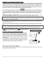
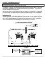
REMOTE RECEIVER
MOUNTING BOX
(2-GANG BOX)
43-3/16"
FINALIZED
HEIGHT
39-1/4"
FINALIZED
WIDTH
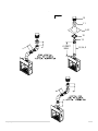
GAS SUPPLY REQUIREMENTS
Correct gas pressure and proper gas supply line sizing is imperative to the successful performance of your Mendota gas
fireplace. Be sure the gas supplier or plumber carefully checks for correct gas pressure and gas line sizing when installing the fireplace.
GAS LINE INLET
1/2" FNPT REQ'D
It is critical to carefully check for gas leaks when hooking up the fireplace -- check with soap & water solution.
Be sure to install "approved" flex gas line with brass-to-brass fittings to prevent gas leaks at connections.
Gas supply piping must include a drip leg to eliminate the possibility of contaminants entering the gas train.
Adhere strictly to local and national codes for entire
installation.
Figure 8: Gas Supply
FRONT
Correct gas pressure and proper gas supply line
and Electrical Supply
sizing is required.
Inlets Locations
GAS SUPPLY LINE SIZING
This Mendota Gas Fireplace comes equipped with a 1/2"
N.P.T. Female inlet. Gas supply piping must enter the
Fireplace cabinet on the left side.
An approved manual shut-off ball valve, as required by
local codes must be installed at an accessible location.
The appliance and its individual shut-off valve must be disconnected from the gas supply piping system during any
pressure testing of that system at test pressures in excess
of ½ PSIG (3.5 kPa).
110VAC INLET
14-2 CABLE REQ'D
The appliance must be isolated from the gas supply piping
system by closing its manual shut-off ball valve during any
pressure testing of the gas supply piping system at test
pressures equal to or less than 1/2 PSIG (3.5 kPa).
915
16
1
1216
1441
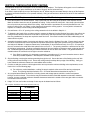
A proper gas line diameter must be selected to run from the supply regulator to the Fireplace. Refer to the following table
for proper gas pipe diameters. Strictly adhere to the correct pipe sizes.
WARNING: Never use any type of pipe thread sealants or compounds on the seats of flare or compression connections.
PIPE LENGTH
(FEET)
0-10
SCHEDULE 40 PIPE
INSIDE DIA.
TUBING, TYPE L
OUTSIDE DIA.
NAT.
L.P.
NAT.
L.P.
1/2" (1.3 cm)
3/8" (1.0 cm)
1/2" (1.3 cm)
3/8" (1.0 cm)
10-40
1/2" (1.3 cm)
1/2" (1.3 cm)
5/8" (1.6 cm)
1/2" (1.3 cm)
40-100
1/2" (1.3 cm)
1/2" (1.3 cm)
3/4" (2.0 cm)
1/2" (1.3 cm)
100-150
3/4" (2.0 cm)
1/2" (1.3 cm)
7/8" (2.3 cm)
5/8" (1.6 cm)
150-200
3/4" (2.0 cm)
1/2" (1.3 cm)
7/8" (2.3 cm)
3/4" (2.0 cm)
NOTE: Some areas allow coated stainless steel (CSST), copper tubing or galvanized pipe - check with local approval agencies and codes. NEVER use plastic pipe.
GAS PRESSURE CHECKING REQUIREMENTS
Inlet and manifold gas pressure checking taps are located on gas valve. Perform inlet and outlet pressure tests before
completing the facing installation. Remove valve access cover box on left side of fireplace to access the gas valve and all
control components.
A qualified installer shall take pressure measurements at these ports to verify and set the correct inlet gas pressures during initial installation. Outlet gas pressures are factory-set and cannot be field adjusted.
NOTE: Check for gas leaks with soap and water solution on all factory joints and field installed joints during first firing of
this appliance.
18 | P a g e
GAS PRESSURE REQUIREMENTS
One of the main causes of operating problems with gas appliances can be improper gas pressure!
Problems such as changes in flame color or configuration, gas pilot or burner outages, intermittent operation, changes in
heat output, excessive burner noise, etc. are nearly always the result of changes in gas pressure or improper gas pressure at the time of the installation. The most important item to check during initial installation and the first thing to check
when problems occur are the input and output gas pressures!
Gas is normally supplied to a residence at 1/2 PSI (13" - 15" W.C.) (3 KPA). A pressure regulator is then placed outside
the residence, near the gas meter, which drops this pressure to 7" W.C. (1.8 KPA) (Nat. Gas). This "inches to inches"
regulator is of adequate capacity to service the gas appliances (such as dryer, furnace, etc.). If this regulator's capacity is
not sufficient to add the Gas Fireplace, an additional "inches to inches" regulator must be installed for the Fireplace.
EXCEPTION: Some codes allow 2-PSI (1.4KPA) supplies to enter the residence, in which case "pounds to inches" regulators are used.
The following table provides information on correct gas pressure requirements. Be sure your gas supplier or plumber
carefully follows this table.
GAS PRESSURE REQUIREMENTS
DESIRED
INLET
PRESSURE
MINIMUM
INLET
PRESSURE
MAXIMUM
INLET
PRESSURE
MANIFOLD
OUTLET
PRESSURE
AIR SHUTTER
POSITION*
NATURAL GAS
7.0" W.C.
(1.75 kPa)
5.0" W.C.
(1.12 kPa)
11" W.C.
(2.61 kPa)
3.5" W.C.
(0.87 kPa)
0 - 1/8 " OPEN
(3 mm)
L.P. GAS
11.0" W.C.
(2.75 kPa)
11" W.C.
(2.75 kPa)
13.0" W.C.
(3.24 kPa)
10.0" W.C.
(2.5 kPa)
1/4" OPEN MIN.
(5 mm)
NOTE: For altitudes above 2.000 feet some variations in air shutter settings may be required.
Manifold pressure must EH WDNHQ DW WKH ³OUTPUT PRESSURE" tap and inlet pressure at the "INLET PRESSURE" tap
with the burner operating by a qualified installer. Perform pressure tests prior to installing facia material around this fireplace.
Figure 9:
Gas Valve Pressure
Test Ports
19 | P a g e
GENERAL INSTALLATION INSTRUCTIONS
CAUTION: Each installation must conform to all local, state and national codes. Refer to the national fuel gas code and local zoning
and code authorities for details on installation requirements. The Mendota Fireplace must be vented to the outside in accordance
with the latest edition of the National Fuel Gas Code. In the absence of local codes, the installation must conform to the most current
edition of the National Fuel Gas Code ANSI Z223.1, also known as NFPA 54. NOTE: The Mendota FV-41 Fireplace is approved for
mobile home and bedroom installations.
CAUTION: The Mendota FV-41 Fireplace may be installed in a manufactured (mobile) home after the first sale of the home. Manufactured home (mobile home) installation must conform with the Manufactured Home Construction and Safety Standard, Title 24
CFR, Part 3280, or, when such a standard is not applicable, the Standard for Manufactured Home Installations, ANSI A225.1/NFPA
501A, or CSA Z240.4-Gas Equipped Mobile Housing. Consult your local building official. Note: For mobile home installations unit
must be bolted to the floor and properly grounded.
The FV-41 Fireplace must be installed by a qualified service person.
HIGH ALTITUDE INSTALLATION INFORMATION: Prior to installing at altitudes greater than 7500, please contact the
Mendota technical service department for specific venting requirements and venting restrictions.
1. After selection of the desired fireplace location, prepare the rough opening using framing dimensions on page 10.
Be sure to also prepare opening to allow for co-axial vent).
2. Check to make certain all venting requirements and locations are being followed.
3. This Fireplace is designed for installation into rough framing. NOTE: FRAMING MATERIAL ABOVE FIREPLACE
MUST MAINTAIN CORRECT CLEARANCE TO FIREPLACE AND VENT PIPES.
WARNING: One-inch clearance to sides & below and inches clearance on top of horizontal vent sections and elbows are required.
4. NOTE: A removable panel in the enclosure for future visual inspection of flue connection is recommended.
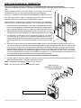
5. Have an electrician install a 115-Volt supply to the junction box on lower left side of the fireplace cabinet. Connect
wires using wire nuts. Make sure the grounding wires are properly connected and that the installation conforms to
all local and national wiring codes.
6. Have gas supplier or qualified plumber install gas supply line to fireplace and FRQQHFWWRWKHò´IHPDOHFRQQHFWRU
Be sure gas and plumbing instructions (see Page 18 and 19) and all local and national codes are carefully followed.
IMPORTANT: Any safety screen, guard, glass, grill etc. removed for servicing this fireplace must be replaced prior to
operating this fireplace.
Figure 10: Junction Box
BLOWER OPERATION
The blower output can be regulated with the remote (included). NOTE: There will be a time delay in blower
operation during "heat-up" (5 min.) and extended blower
operation during "cool-down" of unit (12-1/2 min.).
Backup batteries are located inside the wallmounted remote receiver box. Change the batteries
at least once a year.
110VAC INLET
14-2 CABLE REQ'D
915
16
1441
20 | P a g e
GAS LINE INLET
1/2" FNPT REQ'D
OPERATION DURING POWER OUTAGES
The fireplace is designed to operate during power outages on back-up batteries. The blower and Accent Light
will not operate during the power outage.
FRONT
1
1216
GENERAL FLUE VENTING INSTRUCTIONS
The Mendota Fireplace must be vented using the Mendota approved vent system components. Approved brands of vent
components include DuraVent, Amerivent, Selkirk and Security vent pipes and venting components. All warranties will be
voided and serious fire, health or other safety hazards may result from any of the following actions: Installation by unauthorized personnel; installation of any damaged component; unauthorized modification of vent system; installation of any
components not approved by Mendota; failure to meet all clearance requirements; failure to properly twist-lock and positively seal all components. Consult local building codes before beginning the installation.
WARNING
Always maintain required clearances (air spaces) to combustibles to prevent a fire hazard. Do not fill air spaces with insulation. Check installation instructions for minimum clearance requirements between the outer walls of the vent pipe and
nearby combustible surfaces. Be sure to check the vent termination clearance requirements from decks, windows, soffit,
gas regulators, air supply inlets, and public walkways, as specified in these installation instructions and local building
codes.
SAFETY PRECAUTIONS FOR THE INSTALLER: 1) Wear gloves and safety glasses for protection; 2) Exercise extreme
caution when using ladders or on rooftops; and 3) Be aware of electrical wiring locations in walls and ceilings.
This gas appliance and vent system must be vented directly to the outside of the building, and never attached to a chimney serving another solid fuel or gas burning appliance. Each direct vent gas appliance must have its own separate vent
system. Common vent systems are prohibited.
To assure proper venting performance of this high-performance Mendota Direct Vent Fireplace, it is critical that all brands
of vent pipe sections are sealed tightly and leak-proof. This means that all pipe sections must be carefully rotated into the
fully "twist-locked" position.
We strongly recommend that fixed length pipe sections be used in place of telescoping sections whenever possible.
Note: When using vent pipe and components that do not incorporate a fiberglass or graphite gasket at the inner exhaust
tube joints, you must use Milpak 1000F silicate stove sealant (#65-06-00909). Aluminum foil tape may be used on the
outer (air intake) pipe joint but is not mandatory. Local Codes may vary. Contact your dealer for proper materials.
Do not separate telescoping sections. They must be used as complete assemblies.
Figure 11: Twist-Lock Piping
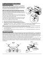
COMPONENT "TWIST-LOCK" CONNECTION PROCEDURE
DuraVent and American Metals pipe and fittings are designed with special
twist-lock connections. Twist-lock procedure is as follows: four (4) indentations, located on the female ends of pipes and fittings are designed to slide
straight in to the male ends of the adjacent pipes and fittings, by orienting the
four pipe indentations so that they match and slide into the four entry slots on
the male ends.
Push the pipe sections completely together then twist-lock one section clockwise, approximately ¼ turn until the two sections are fully locked. The female
locking lugs will not be visible from the outside on the black pipe or fittings.
They may be located by examining inside of the female ends.
HIGH ALTITUDE INSTALLATION INFORMATION
Prior to installing at altitudes higher than 7500, please contact the Mendota technical service department for specific venting requirements and venting restrictions.
21 | P a g e
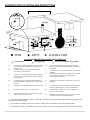
EXTERIOR VENT LOCATIONS AND RESTRICTIONS
Figure 12: Exterior Vent
ALL MEASUREMENTS FROM CENTER-LINE OF VENT CAP
- Vent Terminal
A=
B=
- Air Supply Inlet
Clearance above grade, veranda, porch, deck, or balcony (*12 inches (30 cm) minimum). Vinyl surfaces reTXLUH´PLQ
Clearance to window or door that may be opened
(*12 inches (30 cm) minimum.
- Area where terminal is not permitted
H=
*Not to be installed above a meter/regulator assembly
within 3 feet (90 cm) horizontally from the center-line of
the regulator
I=
*Clearance to service regulator vent outlet *3 feet (92 cm)
minimum.
*Clearance to non-mechanical air supply inlet to building
or the combustion air inlet to any other appliance.
12 inches (30 cm) minimum.
J=
C=
*Clearance to permanently closed window (minimum
12 inches (30 cm) recommended to prevent condensation on window)
D=
*Vertical clearance to ventilated soffit located above
the terminal from the center-OLQHRIWKHWHUPLQDO´ (60
cm) min.
K=
*Clearance to a mechanical air supply inlet 6 feet (1.8 m)
minimum
E=
*COHDUDQFHWRXQYHQWLODWHGVRIILW´PLQFP min.
L=
Clearance above paved side-walk or a paved driveway
located on public property (*7 feet (2.1 m) minimum)
F=
Clearance to outside corner - 7 inches (18 cm).
M=
Clearance under veranda, porch, deck, or balcony (*12
inches (30 cm) minimum Á)
G=
Clearance to inside corner - 12 inches (30 cm). Vinyl
VXUIDFHVUHTXLUH´PLQFP
N=
0LQLPXP´KRUL]RQWDOFOHDUDQFHWRDQ\VXUIDFHVXFKDV
an exterior surface, for vertical terminations.
A vent shall not terminate directly above a sidewalk or paved driveway, which is located between two single-family dwellings and serves both dwellings.
Á Only permitted if veranda, porch, deck, or balcony is fully open on a minimum of two sides beneath the floor.
* As specified in CGA B1:19 Installation Codes (1991). Note: Local codes or regulations may require different clearances.
22 | P a g e
FLUE VENTING COMPONENTS IDENTIFICATION
DO NOT SEPARATE TELESCOPING SECTIONS.
USE TELESCOPING SECTIONS AS COMPLETE ASSEMBLIES.
HIGH ALTITUDE INSTALLATION INFORMATION: Prior to installing at altitudes higher than 7500, please contact the
Mendota technical service department for specific venting requirements and venting restrictions.
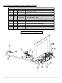
ITEM
1
2
3
4
5
6
7
8
9
10
11
12
13
14
15
DESCRIPTION
RU´3,3('XUD9HQW´$PHULYHQW´
12" VENT STACK
24" VENT STACK
36" VENT STACK
48" VENT STACK
90ºGALVANIZED ELBOW
45º GALVANIZED ELBOW
ADJUSTABLE WALL THIMBLE
ATTIC INSULATION SHIELD 12"
ROOF FLASHING (0/12 TO 6/12)
ROOF FLASHING (7/12 TO 12/12)
STORM COLLAR
VERTICAL VENT CAP
SUPPORT BAND
HORIZONTAL VENT CAP
FIRE STOP SPACER
Figure 13: Flue Venting Components
12
11
9,10
15
13
1,2,3,4,5
6
14
1
23 | P a g e
7
FV-41 MASTER FLUE VENTING REQUIREMENTS CHART
NOTE: THIS CHART IS APPLICABLE TO BOTH NATURAL GAS AND LPG INSTALLATIONS.
IMPORTANT NOTES: See Figure 15, below.
0
1. 18 inches maximum horizontal pipe run allowed with a 90 HOERZFRQQHFWHGGLUHFWO\WRWKLVILUHSODFH¶VIOXHVWDUWHUFRllar.
2. Maximum Vertical Run allowed is 61 feet.
3. Maximum Vent System length allowed is 65 feet.
24 | P a g e
ZONE "A"
IN ZONE "A", ADJUSTABLE EXHAUST DAMPER MUST BE FULLY OPEN.
H max
18"
11'
15¶´
20'
Varies
IN ZONE "B" ADJUSTABLE EXHAUST DAMPER MAY BE FULLY OPEN OR
FULLY CLOSED.
V min
0 in.
6 in.
12 in.
18 in.
24 in.
36 in.
4 ft. - 41 ft.
41ft. - 61 ft.
NOTE: IN ZONE "B", MAXIMUM HORIZONTAL RUN REMAINS 20 FEET
REGARDLESS OF THE NUMBER OF 90° ELBOWS USED.
HIGH ALTITUDE INSTALLATION
INFORMATION: Prior to installing at altitudes
higher than 7500, please contact the Mendota
technical service department for specific venting
requirements and venting restrictions.
THREE 90° ELBOWS MAX IF HORIZONTALLY TERMINATED IN ZONE "B".
4. In =RQH ³$´, 20 feet maximum horizontal
run allowed with a 4 feet starter section. If
the starter vertical section is less than 4
feet, use the chart and reduce 3 feet for
0
0
every 90 elbow installed after the first 90
elbow.
5. In =RQH ³%´, 20 feet maximum horizontal
run allowed only if the first vertical section
connected directly to the top of this fireplace
0
is feet or longer. Three 90 elbows may be
installed anywhere within the 20 feet horizontal run. No reduction in horizontal is re0
quired for the 90 elbows used.
FOUR 90° ELBOWS MAX IF VERTICALLY TERMINATED IN ZONE "B".
Figure 14
ZONE "B"
IMPORTANT VENTING CONFIGURATION NOTES
See Figure 14 [MASTER FLUE VENTING REQUIREMENTS CHART].
HIGH ALTITUDE INSTALLATION INFORMATION: Prior to installing at altitudes higher than 7500, please contact the
Mendota technical service department for specific venting requirements and venting restrictions.
MAXIMUM HORIZONTAL RUN
A. Maximum Horizontal Run allowed is 20 feet if a vertical starter section that is between 4 feet to 41 feet is conQHFWHGGLUHFWO\WRWKLVILUHSODFH¶VIOXHVWDUWHUFROODUDQGQRPRUHWKDQWKUHHGHJUHHHOERZVDUHXVHG
B. Maximum Horizontal Run allowed is ´ if a 90-degree elbow is connected diUHFWO\WRWKLVILUHSODFH¶VIOXHVWDUWHU
collar.
MAXIMUM VENT SYSTEM LENGTH
A. Combined total length of all straight pipe sections in the vent system shall be less than 65 feet.
B. Combined total length of all straight pipe sections in the vent system shall be less than 65 feet when using three
(3) 90-degree elbows or equivalent and terminating the vent system horizontally.
C. Combined total length of all straight pipe sections in the vent system shall be less than 65 feet when using four (4)
90-degree elbows or equivalent and terminating vertically.
HOW TO CALCULATE THE VENT SYSTEM LENGTHS
For calculation purposes and usage of charts in this manual, simply add the lengths of all individual straight pipe sections.
For example: if you use two 2-foot lengths and one 4-foot length, the total vent system length will be 2+2+4 = 8 feet.
0
USING 90 ELBOWS ,1=21(³%´
o
The FV-41 Fireplace by MENDOTA allows maximum flexibility in the use of 90 elbows in the vent system. The length of
the first straight vertical section directO\FRQQHFWHGWRWKHILUHSODFH¶VVWDUWHUFROODUGHWHUPLQHVWKHPD[LPXPKRUL]RQWDOUXQ
0
and the number of 90 elbows allowed for this fireplace.
For vent systems that provide a starting vertical section that is 4 feet or longer, you may connect up to 20 feet of horizon0
tal pipe and up to three (3) 90 elbows within the 20 feet run in any configuration and terminate the vent horizontally. No
reduction in horizontal run is required for the elbows used as long as the 4 feet long vertical starter section is connected
GLUHFWO\WRWKLVILUHSODFH¶VVWDUWHUFROODU.
0
USING 90 (/%%2:6,1=21(³$´
For vent systems that provide a starting vertical section less than 4 feet, the following rules apply:
a. You must use the Master Flue Venting Requirements Chart. 6HH=RQH³$´ EHORZWKH¶YHUWLFDOUXQOLQH
b. A single 90º vertical-to-horizontal elbow is already calculated into the allowable maximum 20' horizontal run. The Vent0
ing Requirements Chart (Figure 14) assumes that for all horizontal runs calculated, one 90 elbow is used within the venting system. Each additional 90º elbow reduces the maximum horizontal distance by 3'.
0
c. If you plan to use more than one 90 elbow within the vent system, first use the Venting Requirements Chart (Figure 14)
and calculate the maximum horizontal run you are allowed based on the first vertical section connected directly to the fire0
place. From this maximum horizontal run calculated, subtract 3 feet for each additional 90 elbow you will use.
Example 1: Assume you are using a 3 feet long starter vertical section. This should allow, per figure 15, 15-1/2 feet of
0
horizontal run. If you want to use three 90 elbows, subtract 6 feet for two elbows from the 15-1/2 feet maximum allowed [3 feet for each elbow after the first elbow]. This yields 9-1/2 feet as the maximum horizontal
run that you are allowed to install using the 3 foot vertical starter section.
CAUTION: If a vertical-to-horizontal discharge elbow or a horizontal-to-horizontal discharge elbow is enclosed within a
wall, floor or ceiling, a top air space clearance of 2" must be maintained.
USING 45-DEGREE ELBOWS
Two 45-degree elbows may be used in place of one 90-degree elbow. On 45-degree runs, one foot of diagonal pipe is
equal to 8-1/2 inches horizontal run and 8-1/2 inches vertical run. Two 45-degree elbows may be connected directly to
the vent starter adapter on this fireplace to create an offset to provide the required clearances to combustible framing or
sheathing materials.
Two 45-degree elbows may be connected directly to the top of this fireplace to create a horizontal offset. 20 feet maximum horizontal run allowed with this offset configuration only if the first vertical section connected directly to the last 45degree elbow is more than 4 feet long. For maximum allowable horizontal distances with the 45-degree offsets, see the
Master Venting Configuration Chart.
Note: Each horizontally positioned 45º elbow reduces the maximum horizontal distance by 1½ '.
SUPPORT: Horizontal runs of pipe will require one vent support for every 3 ft. of pipe.
25 | P a g e
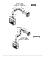
APPROVED VENT SYSTEMS
QUICK REFERENCE CHART
Figure 15: Vent Systems
STRAIGHT UP,
VERTICAL VENTING
ZERO VERTICAL
HORIZONTAL TERMINATION
H
H
VERTICAL RISE
HORIZONTAL TERMINATION
61 FEET
MAXIMUM
V
APPROVED
APPROVED
APPROVED
VERTICAL RISE
DUAL 90° ELBOWS
HORIZONTAL TERMINATION
H
H1
V2
H2
V
H
V1
ZERO VERTICAL
DUAL 90° ELBOWS
VERTICAL TERMINATION
APPROVED
VERTICAL RISE
DUAL 90° ELBOWS
VERTICAL TERMINATION
V
APPROVED
APPROVED
H2
VERTICAL RISE
TRIPLE 90° ELBOWS
VERTICAL TERMINATION
V2
THREE HORIZONTAL DISCHARGE
90° ELBOWS
APPROVED w/ RESTRICTIONS
V2
H1
H1
VERTICAL RISE
TRIPLE 90° ELBOWS
HORIZONTAL TERMINATION
V1
H2
V1
APPROVED
26 | P a g e
APPROVED
APPROVED
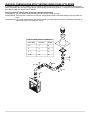
ZERO RISE HORIZONTAL TERMINATION
The FV-41 Fireplace must be installed by a qualified Mendota approved serviceperson.
A Maximum Horizontal Run allowed is 18 inches if a 90-GHJUHHHOERZLVFRQQHFWHGGLUHFWO\WRWKLVILUHSODFH¶VIOXHVWDUWHU
collar.
When a 90-degree elbow is connected directly to this fireplace, the horizontal centerline of the
Figure 16
90ºelbow will be 42-1/2´LQFKHVXSIURPWKHIORRUOHYHORIWKLV)LUHSODFH
See Figure 14, MASTER FLUE VENTING REQUIREMENTS CHART and Figure 17 and Figure 16 below.
Use "fixed" pipe sections in place of adjustable pipe section s wherever possible. 1000º sealant must be used on ALL
inner pipe joints that do not have factory installed gasket material.
Always maintain 1" clearance from vent pipe sides and bottom to combustibles, 2" clearance on top of pipe on horizontal
runs and on top of horizontal discharge elbows. Do not fill air spaces with insulation or other material.
1. Position fireplace in desired location. See Figure 13 for guidelines on proper vent cap placement on the exterior of
home. Check to determine if wall studs are in the way when venting system is attached. If this is the case, you may
want to adjust the fireplace location or modify the exterior wall framing to allow the vent system to penetrate the wall.
2. Measure from the floor level of the fireplace up 45-´ LQFKHV>DGGó´ULVHIRUHYHU\IRRWRIKRUL]RQWDOUXQ@DQGPDUN
wall directly at the center of where the vent pipe will penetrate the exterior wall.
45-1/2"
42-´
3. Cut and frame a 10-3/4" wide x 10-3/4" high opening in the wall. The hole must be positioned so the vent system will
run level or have a ¼" rise per foot of run AND be perpendicular to the wall. The height of the opening must be located to meet all local and national building codes. Do not allow the termination to be easily blocked or obstructed. If
wall being penetrated is non-combustible material, i.e. masonry block, brick, etc., a 9-inch diameter hole is acceptable.
4. Attach the 90-degree elbow to the fireplace starter adapter. Attach a horizontal section to the 90-degree elbow. Be
sure all vent component connections are in their fully twist-locked position and are leak-proof. Be sure 1000ºsealant
is used on the inner pipe joints of all pipe sections manufactured by Simpson DuraVent. The length of the horizontal
piece that fits through the wall will be determined by the location of the fireplace relative to the wall. For a normal installation where this fireplace is installed directly against an exterior wall constructed using 2x4 lumber or 2x6 lumber,
RQO\D´KRUL]RQWDOVHFWLRQLVUHTXLUHG7KHUH0867EHDPLQLPXPRIDLUVSDFHFOHDUDQFHWRFRPEXVWLEles from all
vent components (2" above horizontal runs and horizontal discharge elbows).
5. A wall thimble must always be used when penetrating combustible wall materials.
6. From the exterior of the home, slide the horizontal vent cap over the end of the horizontal pipe and tightly secure the
cap to the wall with screws. Seal with a high quality caulking.
NOTE: Combustible wall thickness must be 4" to 8" maximum
NOTE: Vent Cap should not be recessed into wall or siding.
ZERO VERTICAL
HORIZONTAL TERMINATION
H = 18 INCHES MAXIMUM
H
Figure 17: Horizontal Termination
27 | P a g e
VERTICAL RISE HORIZONTAL TERMINATION
The minimum vertical section required to be connected directly to the starter adapter on this fireplace is 48 inches when
used with a maximum horizontal run of 20 ft. If the total length of the vertical sections connected directly to the starter
adapter on this fireplace is between 4 feet and 41 feet, you are allowed a maximum 20 feet horizontal run. This fireplace
0
provides a maximum flexibility in the use of 90 elbows when more than 4 feet of vertical starter section is connected to
the starter collar. If 4 feet or more vertical section is connected to the starter collar, you may use three 90 degree elbows
and 20 feet of horizontal pipe sections. No reduction in horizontal run is required for the use of the elbows. For other venting configurations within these maximum limits, see Figure 15, Zone A and Zone B.
Combined total length of all pipe sections (include restriction of elbows) in the vent system shall be less than 64 feet.
NOTE: The horizontal run of vent pipe must be level or have a ¼" rise for every 1' of run toward the termination. Never
allow the vent to run downward. This will cause high temperatures and the possibility of a fire.
This FV-41 Fireplace must be installed by a qualified Mendota service person
1. Position fireplace in desired location. See Figure 13 for guidelines on proper vent cap placement on exterior of home.
Check to determine if wall studs are in the way when vent system is attached. If this is the case you may want to adjust the fireplace location.
2. Locate where vent pipe will pass through any ceilings and will penetrate the outside wall. Since vent pipe sections
"overlap" we suggest pre-assembling and measuring the total vent pipe run so you can more accurately locate the
point where the vent pipe will penetrate the outside wall (See Figure 13). Be sure all vent components are properly
twist locked and leak-proof. Be sure 1000º sealant is used in the inner pipe joints of all pipe sections manufactured
by Simpson DuraVent.
3. Cut and frame a 10-´ZLGH[-´´KLJKRSHQLQJLQWKHRXWVLGHZDOORSHQLQJVDQG´[´RSHQLQJ in ceiling
openings. The outside wall hole must be positioned so the vent system will run level or have a ¼" on rise AND be
perpendicular to the wall. The height of the opening must be located to meet all building codes and not allow the termination to be easily blocked or obstructed. A ceiling fire stop spacer is required at any floor (ceiling) opening.
4. Connect vent pipe to the fireplace adapter on top of fireplace vent outlet.
5. The horizontal pipe must end flush with the exterior wall of the home. Horizontal pipe will require a proper support
every 3 ft. of vent pipe. THERE MUST BE A MINIMUM OF 1" CLEARANCE TO COMBUSTIBLES FROM ALL VENT
PIECES ON THE SIDES AND BOTTOM AND 2" ABOVE HORIZONTAL RUNS).
NOTE: DO NOT SEPARATE TELESCOPING SECTIONS.
THEY MUST BE USED AS COMPLETE ASSEMBLIES.
6. A wall thimble must always be used when penetrating combustible wall materials.
NOTE: Combustible wall thickness must be 4" to 8" maximum.
7. From the exterior of the home, slide the horizontal vent cap over the
end of the horizontal pipe and tightly secure the vent cap to the wall
with screws. Seal with high quality caulking.
NOTE: Venting terminal (Vent Cap) should not be recessed into wall
or siding.
V
H
´
´
´
¶-´
¶- 
)RU9JUHDWHUWKDQ
see Figure 15
Figure 18
28 | P a g e
ONE(1) 90° ELBOW
TOP VENT
HORIZONTAL TERMINATION
H
V
Figure 19
APPROVED
Figure 20
29 | P a g e
VERTICAL THROUGH-THE ROOF VENTING
The maximum vertical run of vent pipe is 51 ft. from the top of the fireplace. The fireplace will support a run of a maximum
of 61 ft. Maintain 1" air space clearances on all sides of vents (2" above horizontal runs).
o
If an offset is required directly on top of the fireplace, two 45 elbows may be connected directly to the top of this fireplace
to create a horizontal offset then to run upwards vertically. Doing so will continue to allow the use of the 51 feet maximum
vertical run.
The FV-41 Fireplace must be installed by a qualified Mendota approved serviceperson.
1. Place the fireplace in its desired location. Drop a plum bob from the ceiling to the position of the fireplace flue exit.
Mark the location where the vent will penetrate the ceiling. Drill a small hole at this point. Next, drop a plum bob from
the roof to the hole previously drilled in the ceiling. Mark and drill the spot where the vent will penetrate the roof. Determine if ceiling joists, roof rafters or other framing will obstruct the venting system. You may wish to relocate the
fireplace or to offset, to avoid cutting load bearing members.
2. Cut and frame a 10" x 10" opening in the ceiling centered on the hole drilled in Step No. 1.
3. To determine the length of the vent pipe required, measure the distance from the fireplace flue outlet to the ceiling, the
ceiling thickness and the vertical rise in the attic or second story and allow sufficient vent height above roofline. For
two story installations, fire stops are required at each floor level. If an offset is needed in the attic, additional pipe and
elbows will be required.
4. Assemble the desired lengths of vent pipe and elbows to reach from the fireplace flue outlet. Ensure that all vent pipe
and elbow connections are in their fully twist-lock position and that inner pipe joints (DuraVent only) are sealed and
are leak-proof. Maintain 1" airspace clearances to combustibles (2" above horizontal runs). Cut a 10" x 10" opening in
the roof, centered in the small drilled hole placed in the roof in No. 1. The opening should be a sufficient size to meet
all clearance requirements. Continue to assemble lengths of pipe and elbows necessary to reach up through the roofline. Galvanized pipe and elbows may be utilized in the attic, as well as above the roofline. The galvanized finish is
desirable above the roofline due to its higher corrosive resistance.
a) If an offset is necessary, it is important to support the vent pipe every 3 ft. to avoid excessive stress on the elbows and possible separation. Wall straps are available for this purpose.
6. Slip the flashing over the pipe sections protruding through the roof. Secure the base of the flashing to the roof with
roofing nails and seal flashing to roof. Ensure the roofing material overlaps the top edge of the flashing. Verify you
have at least the minimum clearance to combustibles at the roofline.
7. Continue to add pipe sections until the pipe and the vent cap meet the minimum building code requirements, as outlined in No. 8 on the following page.
a) For multi-story vertical installation, a ceiling fire stop is required at the second floor and any subsequent
floors. The opening should be framed to 10" x 10" inside dimensions as described in step No. 5.
8.
Any occupied areas above the first floor, including closets and storage spaces, which the vertical vent passes
through, must be enclosed. The enclosure may be framed and sheet rocked with standard construction materials,
however, be sure to maintain minimum allowable clearances between the outside of the vent pipe and the combustible surfaces of the enclosure.
9. Height "*H" from roof surface to the top of vent cap can be determined as follows:
10. Complete installation with storm collar and vent cap.
"H" DIMENSION
ROOF PITCH
FLAT to 6/12
7/12 to 9/12
10/12 to 12/12
13/12 to 16/12
17/12 to 21/12
30 | P a g e
FEET
2
2
4
6
8
METERS
.6
.6
1.2
1.8
2.4
.
Figure 21
12
11
9,10
15
13
61 FEET
MAX.
31 | P a g e
1,2,3,4,5
VERTICAL THROUGH-THE-ROOF VENTING USING FOUR 900 ELBOWS
0
In extreme situations, Four 90 elbows may be required to reach a proper exit point for the vent system. Mendota has
spent considerable time and effort in the design of this fireplace and its venting system. Through this effort, Mendota has
0
been able to certify the use of Four 90 elbows.
0
The use of Four 90 elbows must meet some minimum prerequisites.
Prerequisite #1: The vent system must terminate vertically using a vertical vent cap.
Prerequisite #2: There must be a minimum 12 inches of vertical starter section connected directly to the top of this fireplace.
Prerequisite #3: For vertical starter sections less than 4 feet tall, you must reduce 6 feet off the maximum horizontal run
allowed per Figure 15 on page 21, Zone A.
FOUR 90° ELBOWS, VERTICAL TERMINATION
V1(12" MIN.)
H1+H2+H3
V2 MAX
12"
3'
60'
2'
5'
58'
3'
9'
55'
4'- 40'
24
41'
V2
H2
H1
H3
V1
32 | P a g e
FV-41 DOOR OPERATION
TO REMOVE DOOR
1. Use the glass latch tool to disconnect the spring latches from the glass frame. Insert tool into hole in latch,
pull towards you and Rotate 90 degrees to disengage top latches. Remove tool. There are two spring
latches on top of this gas fireplace.
2.
With both hands, rotate top edge of glass frame away from unit 12 inches.
3. Lift glass frame up 1 inch, at an angle, and move away from unit.
4. Door is now free from unit.
TO REPLACE DOOR
1.
2.
3.
4.
5.
Line up the three bottom tabs in glass frame bottom with slots in glass clips on firebox bottom. Insert
tabs into slots and center tabs in slots, left to right.
Center Glass Frame over Firebox; left to right.
After door has been placed into slots, rotate door towards firebox until gasket seal is touching the firebox
frame.
Use the tool provided to connect the spring latches to the glass frame. Insert tool into hole in spring
latch, pull latch towards you, rotate latch so the hook is facing downward then release latch to hook to
door frame.
Door is now connected and sealed to unit.
The following Check-Off Lists must be completed prior to final operation of the Fireplace.
1.) INSERT
2.) PULL
3.) ROTATE
4.) RELEASE
33 | P a g e
INSTALLATION CHECK OFF LIST
Co-axial vent rigid pipe, wall vent cap or roof vent cap must be installed by a Mendota
approved person in accordance with instructions. All joints must be secured, "twistlocked" and leak-proof. 1000ºF sealant must be used on the inner pipe joints of all DuraVent pipe sections.
Horizontal or vertical vent cap must be installed "right-side-up" and tightly sealed to
structure per instructions. Vent Caps must be Mendota approved.
Proper exterior and interior clearances for vent systems and locations for wall vent
cap/roof vent cap must be maintained.
Carefully check for correct gas pressure, proper size gas lines and for gas leaks.
115 V electrical service and gas supply must be installed in accordance with instructions
and local and national codes.
LIGHTING CHECK OFF LIST
All items on "Installation Check Off List" (see above) must be completed.
Check for gas leaks and gas pressures prior to installing facing materials.
Install fresh batteries in Wall Receiver and remote transmitter. )ROORZ³,QLWLDOL]LQJWKH6\sWHPIRUWKHILUVWWLPH´LQVWUXFWLRQVWRV\QFKURQL]HWKHUHPRWHFRQWURODQGWKHZDOOUHFHLYHU
Check air shutter opening - 0" to 1/81DWJDVRU´WR ´/3JDV
Carefully follow all Lighting and Log Installation Instructions.
Make certain that burners light immediately and flame runs promptly around "curve" in
rear burner and lights entire burner. DO NOT proceed with operation unless burner
cycles "on/off" without delays.
Make certain that the flame is "stable" and does not "lift" off burner. If flame lifts off burner, turn unit off and check that all vent pipes are "twist locked" and leak proof, the vent
cap is "right side up" and that 1000º Sealant has been used on the inner pipe joints of all
DuraVent pipe sections. DO NOT proceed with operation if flame is "lifting off" burner.
Note: Do not separate telescoping sections. They must be used as complete assemblies.
34 | P a g e
Make certain glass door is in proper closed position and "centered" in firebox opening.
BLOWER SYSTEM INFORMATION
WARNING: Label all wires prior to disconnection when servicing controls. Wiring errors can cause improper
and dangerous operation. Verify proper operation after servicing.
This appliance is equipped with a three-prong (grounding) plug for protection against shock hazard
and should be plugged directly into a properly grounded three-prong receptacle. Do not cut or remove the grounding prong from the plug.
Dual blowers are provided as standard equipment with this FV-41 fireplace. The dual blowers have an air output rating
of 210 CFM (in free air). This fireplace is designed to operate with the blowers turned OFF or ON. Turning the blower
on increases the overall efficiency of this fireplace and aids in distributing and circulating heat to the room this fireplace
is installed in.
BLOWER OPERATION
The remote control system supplied with this appliance can turn the blowers ON or OFF and regulate the speed of the
blowers in six(6) steps.
NOTE: In the Normal Thermostat Mode and the SMART Mode, there will be a time delay in blower operation during
"heat-up" (5 minutes) and extended blower operation during "cool-down" of unit (12-1/2 minutes).
FV-41 BLOWER WIRING DIAGRAM
BLOWER MODULE ON/OFF POWER SWITCH INDICATOR SYMBOLS
³__´
INDICATES
³21´
35 | P a g e
³2´
INDICATES
³2))´
FLAME APPEARANCE ADJUSTMENT
AIR SHUTTER ADJUSTMENTS
Be sure burner and logs are properly installed (see FV-41 Log Set Installation Section). After burner has been properly installed and operated for 20 minutes, small additional adjustments to the air shutter may
be necessary for final flame appearance. These small shutter adjustments can be made by following these procedures:
127(6WDUWZLWKWKHUHDUEXUQHUDLUVKXWWHUVHWDW´RSHQ for
1*DQGó´RSHQIRU/3*%RWKWKH)URQWDQG5HDUEXUQHUVKXtters can be manipulated with the fireplace operating. Opening the
shutter will yield shorter and blue(er) flames and closing the shutter will
yield taller and yellow(er) flames.
CLOSE
OPEN
FRONT BURNER
AIR SHUTTER
The front burner air shutter adjustment lever is located below the Glass
'RRU)UDPHRQWKHOHIWVLGH6OLGHWKHOHYHUWRWKH³OHIW´WR&/26(DQGWR
WKH³ULJKW´WR23(1WKHIURQWEXUQHUVKXWWHU
The rear burner air shutter adjustment lever is located below the Glass
'RRU)UDPHRQWKHULJKWVLGH6OLGHWKLVOHYHUWRWKH³ULJKW´WR&/26(
DQGWRWKH³OHIW´WR23(1WKHUHDUEXUQHUVKXWWHU
OPEN
CLOSE
REAR BURNER
1. Install logs and glass frame, and burn unit for 20 minutes
AIR SHUTTER
2. If flame is too "blue" open Air Shutters until flames turn yellow.
3. If flames are too "orange" or are causing sooting, open Air Shutters
until flames begin to turn blue. NOTE: If sooting does not stop, turn off fireplace & call a Mendota Service Person.
IMPORTANT: Try each new shutter setting for approx. 1/2 hour before making additional changes.
NOTE: Changes in front burner flame can be made by re-arranging the coals as well. Densely packed coals will yield
more glow and blue flames. Loosely packed coals will yield less glow and yellow flames.
4. For NG applications, start wiWKWKHUHDUEXUQHUDLUVKXWWHURSHQ´)RUKLJKDOWLWXGHDSSOLFDWLRQVDLUVKXWWHUPD\
need to be open further.
5. )RU/3*DSSOLFDWLRQVVWDUWZLWKWKHUHDUEXUQHUDLUVKXWWHURSHQó´)RUKLJKDOWLWXGHDSSOLFDWLRQVDLUVKXWWHUPD\
need to be opened further.
VENT DAMPER ADJUSTMENTS
This fireplace is equipped with a vent damper system that can be adjusted using the glass latch tool. Locate damper adjustment rod above the glass frame in convection chamber at the center. 127(,IWKLVILUHSODFH¶VYHQWLVterminated vertiFDOO\WKHGDPSHUSRVLWLRQPD\EH)8//23(1RU)8//&/26(',IWKLVILUHSODFH¶VYHQWLVWHUPLQDWHGKRUL]RQWDOO\'2
NOT CLOSE the vent damper completely. Adjust position of damper by judging the flame characteristics after 20 minutes
of burn time. If the flames ghost off burners or if sooting occurs [in LPG units], open the vent damper FULLY and work
backwards in increments to determine the correct damper position for that particular installation.
Use a flash light to look into the convection air cavity and note the Damper Position Indicator. Hook glass latch tool in the
hole at the end of the damper rod, SXOORXWZDUGDERXW´DQGWXUQFORFNZLVHWRFORVHWKHYHQWGDPSHU, release. Use a
flashlight to inspect the damper position. The base of the damper adjustment rod has a pointer that indicates the position
of the damper.
ACCENT
LIGHT
HOUSING
90°
CCW OPENS
DAMPER
CW CLOSES
DAMPER
PULL OUT 1/8"
ROTATE CLOCKWISE,
RELEASE.
36 | P a g e
DAMPER
POSITION
INDICATOR
Hook Latch
Tool In Hole.
TROUBLE SHOOTING THE FV-41 FIREPLACE & MAINTENANCE INFORMATION
SYMPTOM
PROBABLE CAUSES
CORRECTIVE ACTION
1. Thin black coating
(soot) forms on viewing
glass.
A. Incorrect gas pressure
2. Humming or whistling
coming from Fireplace.
A. Normal operating noise.
Some noise is normal. It is caused by the gas supply flowing through the gas
orifice. It is expected from any gas fireplace. Turning the Hi/Lo Knob on the
control can reduce the noise. Turning down the flame will reduce the heat
output of the unit.
3. A change in flame appearance or burner operation.
A. A change in gas pressure.
Have your gas supplier check for correct gas 7" W.C. Nat. Gas; 11" W.C. LP
Gas). If flame still needs adjustment see "Flame Adjustment" below.
Clean out carbon, spider webs, lint, etc. from shutter area.
Logs and burner.
&KHFN9HQW&DS¶V AIR INTAKE and Exhaust OUTLET ports.
B. Not enough combustion
air
B. Vent system restricted.
Have gas supplier check for correct gas inlet pressure (7" W.C. Nat. Gas; 11"
W.C. LP Gas).
If sooting continues, open air shutter on burner (see "Gas Flame Adjustment"
below).
If sooting still continues, shut off unit and call Mendota service person.
NOTE: To clean glass - remove glass and wipe glass with cloth or paper towel.
OVER FIRING OF BURNER
NEVER "over fire" units by adjusting gas pressure or drilling out the orifice to increase BTUH above nameplate specifications. Over firing can cause permanent damage to firebox and deterioration of parts and void warranty.
MAINTAINING CORRECT PILOT-FLAME, PILOT OUTAGE & RELIGHTING
The pilot flame must be checked during initial installation and annually by a qualified Mendota Technician. This appliance
utilizes Flame Rectification Technology. If the pilot flame is turned down too low, the flame sensor may not detect the pilot
flame and the pilot light may not stay lit. Do not turn down the pilot light flame. Use the IPI mode instead during summer
months.
CLEANING VIEWING GLASS
The viewing glass should be cleaned periodically. Exterior glass surface may be cleaned with cleaner as desired. To
clean interior surface of glass - use soap and water. CAUTION: Do not use oven cleaner to clean glass. Clean the glass
only when it has cooled to room temperature.
NOTE: Additives that are put in gas (both natural and propane) to make it smell can be harmful to glass and can leave a
ZKLWHILOPGHSRVLWRQWKHJODVV7KLVGHSRVLWFDQEHUHPRYHGZLWKFOHDQHUVVXFKDV.(/.(0³3ROLVK3OXV´SDUW# 65-0600455) or comparable product (contact your dealer).
In some cases (especially when burning SURSDQHDGGLWLYHVFDQFDXVH³FUD]LQJ´RUHWFKLQJRf the glass. This is not a
common occurrence+RZHYHUDQ\³FUD]LQJ´RUHWFKLQJRIWKHJODVV is not covered under the warranty. The solution may
be to change propane suppliers.
SOOTING
Sooting is caused by improper installation or air shutter operation. However, some small areas of soot deposits on log
surfaces are deemed acceptable. If you observe large soRWDUHDVODUJHUWKDQ´[´RQORJVXUIDFHVRUVLJQVRIVRRWLQJRQ
the door glass (usually a thin black film on the Fireplace viewing glass or on the outside of the home around the vent cap),
the unit must be immediately turned off and the local Mendota dealer promptly informed. Mendota dealers will correct
"sooting" problems, but Mendota and their dealers are not responsible for
damage caused by excessive sooting that has not been immediately brought
BALL
to their attention.
ON
OPERATION DURING POWER FAILURE
This fireplace is designed to operate during power outages. Blowers and the
Accent Light will not function during power outages. However, all burners will
continue to function normally. Heat output will be reduced slightly without the
blower functioning (approximately 5% less).
GAS SHUTOFF PROCEDURES
This gas fireplace is equipped with a manual ball shutoff valve that is located
on the left side and within the left convection air cavity. The manual ball shutoff
valve is designed to be manipulated using the glass latch tool. Insert bent end
RIWRROLQWRWKHKROHLQWKHEDOOYDOYH¶VPHWDOKDQGOHVKDSHGOLNHDQDUURZ
head) and rotate ball valve downward to OFF or upward to ON.
37 | P a g e
OFF
VALVE
HANDLE
MAINTENANCE
1. ANNUAL MAINTENANCE OF MENDOTA UNITS IS REQUIRED. The following procedures must be performed
each year by a Mendota approved service person. NOTE: Any adjustments to burner, pilot or logs must be done
by a qualified Mendota service person.
A. Clean all lint and dust build-up around the control. Inspect the condition of any wiring under the burner for melting
or damage.
B. Remove logs & coals and clean away any foreign matter (lint, Carbon, etc.) on the burner and logs. Be sure the
burner ports are "open". Clean the pilot and under side of the logs for any Carbon deposits. NOTE: Logs should
be visually checked for Carbon "build-up". If carbon deposits are visible on logs, unit should be turned off and
Mendota service person contacted. Be sure logs are re-installed per instructions on PAGE 34.
C. Check condition of glass door gasket, gasket must seal tightly over firebox, replace if necessary.
D. Periodically check to verify that the vent system and vent cap are
open and free of blockage.
E. Before re-installing glass, have qualified service person check the
operation of the pilot with millivolt meter and cycle the burner per
LIGHTING INSTRUCTIONS (see PG. 43). Be sure all items in
LIGHTI1*DQG,167$//$7,21FKHFNRII´OLVWVDUHFRPSOHWHG
1. The viewing glass should be cleaned periodically. Exterior glass
surface may be cleaned with cleaner as desired. To clean Interior
glass surface, use Kel Kem ³SROLVKSOXVSDUW-06-00455) or
comparable product. Do not use oven cleaner or abrasive cleaners to clean glass. Do not clean when glass is hot.
2. Periodic visual check of pilot flames is required. Pilot Flame must
overlap Flame Sensor and burner ignition ports at all times.
3. Periodic visual FKHFNRIPDLQEXUQHU¶V rear and front flames is required.
1" MIN.
1" MIN.
1" MIN.
BURNER FLAMES GENERAL HEIGHTS REFERENCE DIAGRAM
HOOD
SPARK ROD
FLAME SENSOR
38 | P a g e
NATURAL TO LP GAS CONVERSION
Kit # HA-78-00179 for Mendota Model FV-41
This conversion kit shall be installed by a qualified service agency in accorGDQFHZLWKWKHPDQXIDFWXUHU¶VLQVWUXFWLRQVDQGDOODSSOLFDEOHcodes and requirements of the authority having jurisdiction. If the information in these instructions is not followed exactly, a fire, explosion or production of carbon
monoxide may result causing property damage, personal injury or loss of life.
The qualified service agency is responsible for the proper installation of this
kit. The installation is not proper and complete until the operation of the converted appliance is checked as specified in the owner instructions supplied
with the kit.
REMOVE LOG GRATE
Caution: The electrical supply to the fireplace must be turned off prior to performing the conversion. The gas supply must be shut off prior to disconnecting the electrical power.
ORIFICE SIZES REQUIREMENT:
A Natural Gas to LPG conversion kit #HA-52-00145 must be ordered and installed to convert the FV-41 Fireplace to burn LPG.
LP Conversion Kit #HA-78-00179 contains the following parts: One Motorized LP Pressure Regulator, One LP Pilot Orifice Thimble, and two Cap Orifices drill #54.
REMOVE SCREWS
FIRST.
LIFT UP AND
REMOVE
FLOOR PANELS
Recommended Procedure To Convert This Fireplace To Burn LPG
This fireplace arrives from the factory ready to burn Natural Gas. If you intend to
burn LPG, it is highly recommended that you convert this fireplace and its
Pressure Regulator, Pilot Orifice Thimble and Burner Orifices prior to placing this fireplace in its framed cavity.
FLOOR PANELS
See diagrams, on this page, and follow these instructions to prepare this fireplace for conversion to LPG.
8VLQJDó´+H['ULYHUUHPRYHVFUHZVWKDWVHFXUHWKH/RJ*UDWHLQ
place. Remove Grate from Firebox.
2. Remove the Floor Brick Panels by lifting them out of the firebox.
3. Carefully remove Left Brick Panel. Push rear end of Baffle Brick upward
about ¼ inches and hold in place with right hand. Tip Left Brick Panel
inward using left hand and carefully release left side panel and guide it
out of firebox.
1. PUSH REAR END
OF BAFFLE BRICK
UPWARD ABOUT
1/4 INCHES.
2. TIP LEFT BRICK
PANEL INWARD
AND RELEASE
CAREFULLY.
1.REMOVE 8 SCREWS THAT SECURE LEFT
BLOWER ASSEMBLY COVER TO LEFT SIDE OF
FIREBOX.
2. SLIDE BLOWER & COVER PLATE INTO FIREBOX.
DISCONNECT BLOWER WIRES & REMOVE
BLOWER ASSEMBLY.
BLOWER
ASSEMBLY
39 | P a g e
WARNING: It is of the utmost importance that the correct burner orifices be installed for both the rear and front
burners.
It is highly recommended that you remove the left side blower assembly and the left side exterior controls box
before attempting to replace the pressure regulator.
1. Turn off gas supply at the appliance service valve.
2. See diagrams on this page and identify the Pressure Regulator on the
VIEW FROM OUTSIDE FIREBOX
Valve Body.
3. Using a Torx T20 or a slotted screwdriver, remove 2 screws that secure the NG Pressure Regulator to the gas valve body and remove
NG Pressure Regulator, see following page.
4. Install the new LP Pressure Regular onto the gas valve body in the
same position and orientation as the NG Pressure Regulator you removed in Step 2, above. The LP Pressure Regulator can only be
mounted in one position. Secure the LP Pressure Regulator in place.
Tighten down.
5. Remove both Rear and Front Burners. Locate and Identify the Rear
Burner Orifice Spud and the Front Burner Orifice Spud. Both Front
DQG5HDU2ULILFH6SXGVDUHUHPRYHGDQGLQVWDOOHGXVLQJDò´GHHS
well socket and ratchet.
6. Install Rear Burner Orifice #65-14-00054(#54 drill) for the Rear Burner. Tighten down securely.
7. Install Front Burner Orifice #65-14-00054 (#54 drill) for the Front
Burner. Tighten down securely.
PRESSURE
7. Install pilot orifice thimble #05-04-´VHH)LJXUH5 for loREGULATOR
cation. To remove Pilot Hood, use a screw driver to pry open the Wire
Clip that is located at the base of the Pilot Hood. Pull Upward and remove pilot hood. Use an Alan wrench to remove
NG Pilot Orifice. (Pilot orifice thimble is located inside pilot hood base).
8. Install LP Pilot Orifice. Tighten down using an Alan wrench. Replace Wire Clip in its original position.
9. Push Pilot Hood down into base until it snaps in place.
Motorized
LP Pressure
Regulator
[10.0-5.5"WC]
Pull Pilot Hood UP
and lift UP off the base.
Use an Alan Wrench
To loosen and remove
NG Pilot Orifice. Install
LP Pilot Orifice, Tighten
Down.
WIRE
CLIP.
Burner Orifices
[#54 X2]
LP Pilot Orifice
ORIFICE
WASHERS (2)
3/8" COMP X 1/8NPT
BRASS FITTING
MOTORIZED PRESSURE
REGULATOR
REAR ORIFICE
INSIDE HERE.
FRONT ORIFICE
INSIDE HERE.
PILOT LIGHT HOOD
40 | P a g e
LP PRESSURE REGULATOR CONVERSION INSTRUCTIONS
WARNING: Failure to position the parts in accordance with these diagrams or failure to use only parts specifically approved with this appliance may result in property damage or personal injury.
41 | P a g e
LP GAS PRESSURE REQUIREMENTS
Inlet and manifold gas pressure checking taps are located on gas valve. These ports are only accessible from the outer
left side of the fireplace. A qualified installer shall take pressure measurements at these ports to verify and set the correct
gas pressures during the LP Kit installation and before facia materials are installed over the front of this fireplace. Manifold
pressure must EHWDNHQDWWKH³0$1,)2/'35(6685(WDSDQGLQOHWSUHVVXUHDWWKH,1/(735(6685(WDSwith the
burner operating by a qualified installer.
L.P. GAS
DESIRED
INLET
PRESSURE
MINIMUM
INLET
PRESSURE
MAXIMUM
INLET
PRESSURE
MANIFOLD
OUTLET
PRESSURE
AIR SHUTTER
POSITION
11.0" W.C.
(2.75 kPa)
11" W.C.
(2.75 kPa)
13.0" W.C.
(3.24 kPa)
10.0" W.C.
(2.5 kPa)
1/4" OPEN MIN.
(5 mm)
REGULATE THE FLAME HEIGHT TO "HIGH" POSITION. OUTLET GAS PRESSURES MAY VARY PLUS OR MINUS 5%.
LPG PROPER INPUT RATES:
With the proper orifices installed, as specified above, this
fireplace utilizing LP Gas will have a maximum input rate of
40,000 Btu/Hr.
LEAK TESTING REQUIREMENTS
Prior to completing the conversion process, check for gas
leaks with soap and water solution at all plumbing joints
prior to placing this appliance into operation. It is recommended that all gas-plumbing joints, factory installed and
field installed are checked for leaks.
Figure 23: Pressure Test Port
PILOT FLAME AND MAIN BURNER RELATIONSHIP
VERIFICATION
Prior to completing the conversion process, the qualified
service technician must, light the pilot light and verify the relationship between the pilot light flames and the main burners.
The pilot light flames directed towards the propagation ports on the rear and front burner must overlap the propagation
SRUWVRQWKHEXUQHUV7KHSLORWOLJKWIODPHVPXVWEHDPLQLPXPRIô´ORQJDQGPXVWRYHUODSWKHSURSDJDWLRQSRUWVRQERWK
the rear and front burners as shown in the diagram, below. Verify that the burner tubes ignite quickly and the burner
flames propagate smoothly along the entire length of the burners.
PILOT FLAME LENGTH ADJUSTMENT
If the pilot light flame length is too short and the system does not maintain a standing pilot, a qualified installer may
increase the length of the pilot light flames to meet the two requirements: Minimum pilot light length to maintain a
standing pilot light and the pilot light flames must be long enough to overlap the front and rear burner ports.
1" MIN.
1" MIN.
1" MIN.
42 | P a g e
Pilot Flame
must overlap
Burner Ports
CHECKING FOR NORMAL BURNER (S) IGNITION CHARACTERISTICS
Once the conversion to LPG and all the above steps have been completed, light the main burners.
Turn Gas Dial counterclockwise to "ON" then set Thermostat or push Main Burner ON/OFF switch to turn on burners.
Main burner should now light IMMEDIATELY and flame should not "lift" off burner. If there is any delay in ignition or if
flame is "lifting off" burner, turn off burner and carefully check for proper installation of logs/coals, vent system and proper
pilot flame impingement on burner. Logs or coals must not block pilot flame or main burner flame. Vent system must be
leak proof.
WARNING
DO NOT PROCEED WITH OPERATION OF THIS FIREPLACE
UNLESS BURNER "CYCLES" ON/OFF WITHOUT DELAYS!
ATTACHING LPG CONVERSION LABELS AND HIGH ALTITUDE DERATION LABEL
Two printed informational labels are included with the LPG Conversion Kit. Attach these two labels to the back surface of
the Serial Number Plate that is located in the convection air cavity below the firebox. If you are derating this appliance at a
high altitude, also attach the High Altitude 'HUDWLRQ/DEHOVXSSOLHGLQWKH2ZQHU¶V0DQXDO3DFNHWWRWKLVVDPHVXUIDFH
Prior to attaching the labels, fill in all the information that is requested in these labels.
For installations from 610-1370 meters (2000-4500 ft.) the orifice sizes (DMS) for natural and propane gas are
_43_ and _55_, respectively. See data plate for additional information. For high altitude installations consult
the local gas distributor or the authority having jurisdiction for proper rating methods. If the installer must convert the unit to adjust for varying altitudes, the information sticker must be filled out by the installer and adhered
to the appliance at the time of conversion."
«Cet appareil est equipé pour des altitudes compries entre 0 et 2000 pieds (0-610 m) seulement»
This appliance has been converted for use at an altitude of ______________
Orifice size _______________
Manifold Pressure ________________
Input (Btu/h)_______________
Fuel Type _______________________
Date of conversion _________
Converted by _____________________
«Cet appreeil a été converti au ____
Injecteur ________
Pression à la tubulure d'alimentation _____________
Déoit calorifique ______________
43 | P a g e
FV-41 VALVE ASSEMBLY REPLACEMENT PARTS
ITEM
1
2
3
4
5
6
7
8
9
10
11
12
QTY
1
2
1
2
1
1
1
1
2
1
1
1
FV-41 VALVE ASSEMBLY REPLACEMENT PARTS LIST
PART NUMBER
DESCRIPTION
HA-77-00159
VALVE HEAT SHIELD
65-07-00024
1/8 NPT to Flex CF Coupler
05-04-00050
SIT Pilot Assembly
65-14-00042
ORIFICE, #42 22,197 BTU NAT
05-02-00344
885 PROFLAME SIT VALVE
05-02-00351
Solenoid, 885 PROFLAME SPLIT FLOW VALVE
60-01-00018
NIPPLE, 3/8" NPT X 1.5" LONG, 0.493 ID, BLACK
65-07-00753
Elbow 90 Deg, 3/8 Flared Tube X 3/8" NPT Male, Brass
65-07-00012
BCF,3/8 TBE X 3/8MPT COMP ELBW
55-02-00089
3/8" FLARED FLEXTUBE, SS X 9"
55-02-00073
TUBING, 3/8" OD X 10" SS 304
55-02-00088
TUBING, 3/8" OD X 30" SS 304
Figure 24: FV-41 VALVE ASSEMBLY
44 | P a g e
FV-41 GAS IGNITION SYSTEM WIRING DIAGRAM
45 | P a g e
GLASS FRAME ASSEMBLY REPAIR AND REPLACEMENT
DO NOT substitute other manufacturer's materials or components.
DO NOT operate unit with cracked,
broken or missing glass.
DO NOT abuse the glass door by
striking the glass, slamming the
door shut, etc
WARNING
Use only authorized parts and
materials obtained from Johnson
Gas Appliance Company when
replacing defective or damaged
glass.
WARNING
Do not operate this appliance
with the glass removed, cracked
or broken. Glass should be replace by a licensed or qualified
person.
TO REPLACE DAMAGED GLASS
1. Bend Glass Retainer Tabs up 90 degrees. Four tabs hold down the glass and gasket assembly.
2. Remove the damaged glass and gasket material. Clean the inner surface of the glass frame.
3. Assemble new gasket on glass edge starting with the bottom left corner. The adhesive on the gasket should
make contact with the glass surface. Use tracer lines in gasket to determine where the glass should sit on the
gasket surface. See Figure 263.
4. Place glass and gasket assembly in glass frame and carefully bend down glass retainer tabs. Extra glass retainer
tabs are provided should any originally used tabs break off.
Figure 25
The glass frame assembly and its individual components are available
through Johnson Gas Appliance Company. Contact your dealer for more
detailed ordering information.
TAB #2
GLASS FRAME ASSEMBLY # HA-78-00103
REPLACEMENT PARTS LIST
ITEM
PART NUMBER
1
HA-78-00XXX
2
65-02-00103
3
65-06-01184
DESCRIPTION
FRAME, WELDMENT, GLASS,
FV-41
GASKET, TADPOLE,
´%8/%´7$,/
GLASS, CERAMIC, FV-41
Figure 26
Figure 27
GASKET
GLASS
ROTATE GASKET UP
SO ADHESIVE MAKES
CONTACT WITH GLASS
SURFACE
GASKET IN
FLAT FORM
TRACER LINES
IN GASKET
ADHESIVE
GLASS SHALL SIT BETWEEN
TRACER LINES IN GASKET
46 | P a g e
USE LARGE PLIERS TO
BEND DOWN (4) TABS
AS SHOWN
GASKET
GLASS
LISTING LABEL INFORMATION
The model information regarding your specific appliance can be found on the rating plate, which is located inside the right
side controls access door. When contacting your dealer for any cleaning service or warranty service, always provide the
Model Number, Serial Number and Manufactured Date. This information will expedite the warranty verification process.
47 | P a g e
MENDOTA WARRANTY QUALIFICATION & SERVICE REFERENCE FORM
As a part of Mendota's on-going program of customer satisfaction, this Form verifies proper installation and operation. It is important as a reference for future service. It insures long life and trouble-free operation of Mendota fireplaces & stoves and qualifies the owner for Mendota's lifetime limited warranty. Owner should sign Form when completed and mail a copy along with
Warranty Registration to Mendota. OPTIONALLY, PLEASE REGISTER AT OUR WEBSITE AT:
WWW.JOHNSONGAS.COM/MENDOTA-REGISTRATION.ASP
HOME OWNER: ________________________________
DEALER: _________________________________
ADDRESS: ____________________________________
ADDRESS: _______________________________
CITY/STATE/ZIP: ______________________________
CITY/STATE/ZIP: __________________________
SIGNATURE: __________________________________
MODEL #: FV-41
SERIAL #: _______________
PHONE: __________________________________
DATE INSTALLED: ________________________
Mendota direct vent fireplaces are sophisticated, hi-tech gas appliances. All installation and operating instructions must be carefully
followed. This FV-41 fireplace must be installed and serviced by a qualified Mendota approved service person.
REF: ___________________ MENDOTA FV-41 INSTALLATION MANUAL
APPROVED VENT PIPES AND VENT CAP INSTALLED - Per Manual.
Vent pipes must be fully twist-locked and leak proof.
Check minimum and maximum vertical / horizontal and vent runs.
1000ºsealant must be used on inner joints at adjustable pipe sections.
CHECK FOR PROPER CLEARANCES TO COMBUSTIBLES & VENT LOCATIONS - Per Manual
INSTALL PROPER SIZE GAS LINES - CHECK FOR GAS LEAKS - Per Manual
CHECK FOR CORRECT GAS PRESSURE AT MANIFOLD - Per Manual
a.
b.
3.5 Inches Water Column Maximum - Nat. Gas
10.0 Inches Water Column Maximum - L.P. Gas
CYCLE BURNERS ON/OFF FOR PROMPT IGNITION - Per "LIGHTING INSTRUCTIONS"
Burner must light IMMEDIATELY - Flame must travel promptly around "curve" & light burner.
INSTALL LOGS AND ADJUST FLAME - Per Manual
Proper pilot flame impingement on burner - Air shutter opening: 1/8" Nat. Gas ± 1/4-³-1/2" LP
Check that flame is "stable" and is not "lifting" off burner
BRIEF OWNER ON OPERATION AND MAINTENANCE OF UNIT
Light Pilot
Operate Burner
Train on Remote Control Functions
Explain Thermostatic Functions
WARRANTY REGISTRATION
Your Name _______________________________________________________________________
Address _________________________________________________________________________
City ________________________________________ State ______Zip ______________________
Dealer (Place of Purchase) ___________________________________________________________
City ________________________________________ State ______Zip ______________________
Date of Purchase _______________________ Serial Number _______________________________
Purchaser's Signature _______________________________________________________________
MENDOTA FV-41 DIRECT VENT FIREPLACE
CUT OUT PAGE AND MAIL TO: JOHNSON GAS APPLIANCE CO., 520 E AVE. N.W., CEDAR RAPIDS, IOWA 52405
PLEASE REGISTER AT OUR WEBSITE AT: WWW.JOHNSONGAS.COM/MENDOTA-REGISTRATION.ASP
48 | P a g e
NOTES
49 | P a g e
TAPE SHUT
-------------------------------------------------------------------------------------------------------------------------------------------------------------
POSTAGE
NEEDED
JOHNSON GAS APPLIANCE COMPANY
520 E AVENUE N.W.
CEDAR RAPIDS, IA 52405
50 | P a g e
MENDOTA EXTENDED LIFETIME PROTECTION AND LIMITED WARRANTY
MENDOTA FV-41 DIRECT VENT FIREPLACE
Mendota Division of Johnson Gas Appliance Company, 520 E Avenue N.W. Cedar Rapids, Iowa 52405, extends this Extended Lifetime Protection and Limited Warranty to the original purchaser of a Mendota FV-41 Fireplace, which is limited and used under normal home conditions.
STANDARD WARRANTY:
JOHNSON GAS APPLIANCE CO., MENDOTA DIVISION, WARRANTS THAT YOUR NEW MENDOTA FIREPLACE IS FREE FROM
MANUFACTURING AND MATERIAL DEFECTS FOR A PERIOD OF ONE YEAR FROM THE DATE OF INSTALLATION, SUBJECT TO THE
FOLLOWING CONDITIONS AND LIMITATIONS:
EXTENDED LIFETIME WARRANTY:
THE HEAT EXCHANGER, BURNER TUBE COMBUSTION CHAMBER AND OUTER SHIELD OF THE MENDOTA FV-41 FIREPLACE ARE
WARRANTED FOR THE LIFETIME OF THE ORIGINAL OWNER, SUBJECT TO PROOF OF PURCHASE AND THE FOLLOWING CONDITIONS
AND LIMITATIONS:
1)
This new Mendota Fireplace must be installed & serviced by a competent, authorized service contractor. It must be installed and operated at all times
in accordance with the installation and operating instructions furnished with the Fireplace. All adjustments to logs, coals or burner must be made by
an authorized Mendota person. Any alteration, willful abuse, accident or misuse of the product shall nullify this warranty. This warranty does not
cover glass or log breakage.
This limited warranty does not cover the cost of service calls, the cost of labor to remove or install parts covered by this limited warranty, freight or
other transportation expenses, which may be incurred in connection with obtaining performances under this limited warranty. The remedy for damages as the result of any defects in this product which have been warranted herein is limited to replacement parts and does not include any incidental,
indirect or consequential damages or expenses sustained in connection with the product, including damages to property, except as provided by law.
2)
This warranty is non-transferable and is made to the original retail purchaser, provided the purchase was made through an authorized Mendota dealer.
Mendota is not responsible for any damage to or malfunction of the Fireplace unless caused by a defect in material or workmanship from normal
home use. Damage caused by abuse, improper installation, improper servicing, and installation by unqualified personnel or breech of conditions of
this limited warranty will excuse Mendota from performance of any part of this limited warranty. Mendota has the right to investigate and inspect the
exact, original Fireplace and entire installation (without any alterations or tampering) in the event a claim is made to determine whether the claimed
damage or malfunction was caused by abuse, improper installation or other cause outside this warranty. Mendota is not responsible for any repairs
or material purchases that have not received prior written approval from Mendota.
NOTE: Minor warping of certain parts or discoloration is normal and is not a defect covered by this warranty. Major warping of parts can be caused by
over-firing of your Mendota Fireplace. Over-firing above rated nameplate specification is as contrary to the manufacturer's instructions and may
void this warranty.
This warranty may not be extended by our representatives or any third party in any manner. The company neither assumes, nor authorizes any third
party to assume, on its behalf, any other liabilities with respect to the sale of this Mendota product.
3)
Mendota may at its discretion, fully discharge all obligations of this warranty by refunding the wholesale price of the defective part(s).
4)
All other warranties - expressed or implied - with respect to the product, its components and accessories, or any obligation/liabilities on the part of the
company are hereby expressly excluded. Products made by other manufacturers, sold with the Fireplace or thereafter, are not covered by this limited
warranty. The use of unauthorized components will make this warranty null and void.
This warranty shall be effective only if the original purchaser of the Mendota appliance is registered with Mendota Division within thirty (30) days of the
date of purchase. Such registration or the failure to register shall not be deemed to create any obligation or liability by the manufacturer and this warranty
with its conditions and limitations shall be the only procedure for obtaining any rights against the manufacturer and expresses the sole obligation and responsibilities of the manufacturer which are offered to the original purchaser and accepted upon purchase of the appliance.
Mendota Division, reserves the right to make changes at any time without notice, in design, material, specifications, prices and the right to discontinue styles
and products.
Some states do not allow the exclusion of limitation of incidental or consequential damages or limitations on how long an implied warranty lasts, so the
above limitation or exclusion may not apply to you. This warranty gives you specific legal rights and you may also have other rights which vary from state
to state
51 | P a g e
Johnson Gas Appliance Company
520 E Avenue N.W. - Cedar Rapids, IA 52405
Mendota Hearth Division
WEBPAGE: www.johnsongas.com or www.mendotahearth.com
52 | P a g e