1
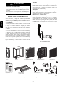
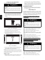
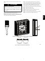
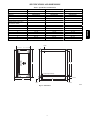
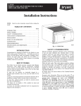
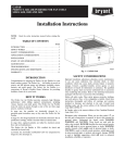
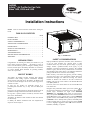
GAPAB Infinity™ Air Purifier for Fan Coils Sizes 1620, 2020 and 2420 Installation Instructions NOTE: install. Read the entire instruction manual before starting the TABLE OF CONTENTS PAGE INTRODUCTION . . . . . . . . . . . . . . . . . . . . . . . . . . . . . . . . . . . 1 HOW IT WORKS . . . . . . . . . . . . . . . . . . . . . . . . . . . . . . . . . . . 1 SAFETY CONSIDERATIONS . . . . . . . . . . . . . . . . . . . . . . . . . 1 APPLICATION CONSIDERATIONS . . . . . . . . . . . . . . . . . . . . 2 INSTALLATION . . . . . . . . . . . . . . . . . . . . . . . . . . . . . . . . . . . . 3 START--UP AND OPERATION . . . . . . . . . . . . . . . . . . . . . . . . 6 MAINTENANCE . . . . . . . . . . . . . . . . . . . . . . . . . . . . . . . . . . . . 6 TROUBLESHOOTING . . . . . . . . . . . . . . . . . . . . . . . . . . . . . . . 8 SPECIFICATIONS AND DIMENSIONS . . . . . . . . . . . . . . . . . 9 WARRANTY . . . . . . . . . . . . . . . . . . . . . . . . . . . . . . . . . . . . . . 11 INTRODUCTION Congratulations for selecting the Infinity Air Purifier for your home comfort system! The Infinity Air Purifier is proven to remove and kill airborne germs and allergens, including viruses, bacteria, and mold spores. The Infinity Air Purifier is a cornerstone of Carrier’s Healthy Home Solutions for providing healthier, cleaner air in your home. HOW IT WORKS The Infinity Air Purifier provides extremely high filtration performance while killing captured contaminants, including viruses, bacteria, and mold spores. The Infinity Air Purifier treats the entire air--stream through a state of the art, three--stage process, exclusive to Carrier. In stage one, the particles are electrically charged by a precision--point ionization array as they enter the Infinity Air Purifier. In stage two, the charged particles are electrically attracted to the air purification cartridge, which is located within an electric field. In stage three, captured particles are killed by electrical current flow and ion bombardment. The Infinity Air Purifier is CSA certified for shock and electrical fire hazard only. La Infinity Air Purifier certification CSA vise uniquement les risques de choc electrique et. A06377 Fig. 1 -- GAPAB Unit SAFETY CONSIDERATIONS Improper installation, adjustment, alteration, service, maintenance, or use can cause explosion, fire, electrical shock, or other conditions which may cause death, personal injury or property damage. Consult a qualified installer, service agency or your distributor or branch for information or assistance. The qualified installer or agency must use factory--authorized kits or accessories when modifying this product. Refer to the individual instructions packaged with the kits or accessories when installing. Follow all safety codes. Wear safety glasses, protective clothing, and work gloves. Have a fire extinguisher available. Read these instructions thoroughly and follow all warnings and cautions included in literature and attached to the unit. Consult local building codes and the current edition of the National Electrical Code (NEC) NFPA 70. In Canada, refer to the current editions of the Canadian Electrical Code CSA C22.1. on Recognize safety information. When you see this symbol the unit and in instructions or manuals, be alert to the potential for personal injury. Understand the signal words DANGER, WARNING, and CAUTION. These words are used with the safety--alert symbol. DANGER identifies the most serious hazards, which will result in severe personal injury or death. WARNING signifies hazards, which could result in personal injury or death. CAUTION is used to identify unsafe practices, which may result in minor personal injury or product and property damage. NOTE is used to highlight suggestions which will result in enhanced installation, reliability, or operation. ! CAUTION PERSONAL INJURY HAZARD Failure to follow this caution may result in personal injury. Ozone in concentrations above 0.05 PPM may be hazardous to health. Des concentrations d’ozone superieures a 0.05 PPM peuvent etre nocives pour la sante. GAPAB APPLICATION CONSIDERATIONS The Infinity Air Purifier is designed for use in the return air duct of a forced air heating, cooling, and ventilation system. Models GAPABXCC1620, GAPABXCC2020 and GAPABXCC2420 are specifically designed for use in systems with a fan coil. Air Conditioning The Infinity Air Purifier should be installed in a system so that all the return air is circulated through the air purifier. It should be located upstream of the fan coil This will help keep the fan coil clean and prevent condensation from forming within the Infinity Air Purifier. Humidifiers An evaporative humidifier can be mounted upstream of the Infinity Air Purifier. It is best to install atomizing humidifiers downstream of the air purifier because hard water salt deposits and water droplets may damage the air purifier. If an atomizing humidifier must be mounted upstream of the Infinity Air Purifier, it should be mounted as far upstream as possible (at least 6 ft. recommended), and a standard disposable furnace filter should be mounted between the humidifier and the air purifier to trap hard water salt deposits and water droplets. Transitions If the return air duct or fan coil openings do not fit the Infinity Air Purifier cabinet openings, gradual transitions are recommended to reduce air turbulence and maximize efficiency. No more than 20 degrees (about 4 in. per running ft.) of expansion should be used on each side of the transition fitting. Turning Vanes If the Infinity Air Purifier is installed adjacent to a 90 degree duct elbow, turning vanes should be added inside duct to improve air distribution across the face of the air purifier. Electrical Power / Air Flow Sensor The Infinity Air Purifier should only be powered when airflow is present. This model is designed for use with a fan coil and is equipped with an air flow sensor which provides power only when the fan coil blower is operating (See Fig. 2). Infinity Air Purifier models GAPABXCC1620, GAPABXCC2020, and GAPABXCC2420 are designed to be powered from a 208/230 VAC power source. A06387 Fig. 2 -- Air Flow Sensor Door (x1) Cabinet (x1) Air Purification Cartridge (x1) Enhancement Module (x1) Safety Screen (x1) GAPA Infinity Air Puri Sizes 1620 fier , 2020, & 2420 Installatio n, Start--Operating up, Instructio and ns NOTE: Readth e entire install. instruct ionmanual befores tartingth e TABLE OF CONTE NTS SAFETY CONSID ERATIONS INTROD ...... UCTION Page ...... ...... PLANN ...... ...... ING . . . . . . . .1 ...... ...... ...... ...... Applica ...... ...... tion. . . . . 2. ...... ...... Installation . . . . . . . . . . . . . . . .2...... Require . -5 ...... ments. . Dimens ...... ...... ions . . . . .2. Table1 ...... ...... Air Conditi ...... . . . . . . . .2 ...... oning. . ...... ...... Humidi ...... ...... fiers . . ....3 ...... . ...... ...... Outdoo ...... . . . . . .5 rAir . ...... . ...... SheetMetalIn . . . . . . . . . . . . . . . ...... ...... .5. stallatio ...... Transiti ...... n. . . . . . ons. . . . . . . . .5. ...... ...... ...... Turning ...... ...... Vanes . ...... . . . .5 ...... ...... SelectLo ...... ...... cation. ...... . . .5. ...... ...... Directio ...... ...... nof Airflow ...... . . . 5. ... INSTAL through LATION Air Purifier . . . . . . . . . . . . 5. ...... ...... Orienta ...... ...... tion. . . . ...... ..5 ...... ...... Details ...... ...... ...... . . 5...... . -6 ...... ...... TypicalM ...... ...... ...... ounting . 5. -6 ...... Position Electric ...... s. . . . . . alInstallation . . . .6. ...... ...... ...... Furnace ...... ...... Applica .6 ...... tion. . . . SYSTEM ...... ...... CHECK . . . . . .6 ...... OUT ...... MAINTE ...... ...... NANCE ...... ..6 . ...... ..... Replaci ...... . . . . . .7 ngPurifierC . . . . . . . . . . . . ...... TROUB artridge ...... LESHO ...... . . . . 7. OTING. ...... ...... Recomm ...... . . . . . .7 ...... ended ServiceT ...... Indicati ...... onof Electric ools. . . . . . . . . . . . .7 ...... OTHER alTrouble ...... FACTS . . . .7 YOU SHOUL . . . . . . . . . . ...... Ozone. D KNOW . . . . . .7 ...... ...... ...... HighAlt ...... ...... itudeOp ...... ...7 ...... eration Specific ...... ...... ations . . . .7. ...... Table2 ...... WARRA ...... ...... NTY . . ...... . . .7 ...... ...... ...... ...... ...... . . . . .8 ...... ...... . . . . .9. (x3) (x2) Fig. 1 -- Unit GAPA (x1) A05265 SAFETY CONSID Improp ERATIO er NS mainten installa tion,ad ance, or otherco or use cancau justme nt,alter ation,s damage nditionswhichm se explos .Consult aycaus ion, fire, electric ervice, distrib epersona a qualifie alshock utoror branch injuryor l dinstaller qualifie for inform , serviceagencyproperty dinstalle ror agencym access , ationor ories assista or your when modify ustusefactoryau individu nce.Th e alinstruction ingthis whenins produc thorizedkitsor spackag talling. edwith the t. Refer to Followa the kits or ll safety acces sories Use quench codes. ingcloth Wear safety gla extingu for brazing sses and isher workglo follow all available. Readth operat ves. localbu warningor caution ese instruct ions.H ave fire ildingco thoroug sattache ions desand specialr dto the unit. hlyand equirem Nationa lElectric . It is importa ents alCode( Consult NEC) for ntto recogn safety--alertsy izesafetyin mbol formati andin instruc . Whenyo on.This is the tions person or manual useethissymbo al s,be alert lontheu WARNI i njury. Unders to the potenti nit NG, andCAU tandthe safety--alertsy signal wordsD TION. alfor Thesew mbol. hazards ANGER ordsare DANGE whichw , usedwit R identifi ill WARNI h the esthe NG signifieresultin severep injuryor shazard ersona mostse rious death. CAUTIO ilnjury or swhichc whichm N is usedto ould resultin death. ay resultin damag person identify person e.N al unsafep resultin OTE is usedto alinjury or produc ractices enhanc ed installat highlightsugge tand propert ion, y stions reliabili ty , or operatiowhichwill n. (x2) 1 (x1) Installation Manual Return Duct Adapters: Long (x2) / Short (x2) Air Flow Sensor (x1) (x2) Installation Components (in bag attached to power cord) A07111 Fig. 3 -- Infinity Air Purifier Components 2 Step 1 — Check Infinity Air Purifier Components ! CAUTION PERSONAL INJURY HAZARD Failure to follow this caution may result in personal injury. Sheet metal parts may have sharp edges or burrs. Use care and wear appropriate protective clothing and gloves when handling parts. Carefully remove all items from the box. Step 2 — Identify Mounting Location a. Identify a mounting orientation for the Infinity Air Purifier in the return air duct (see Fig. 4). b. Ensure airflow direction through the Infinity Air Purifier matches the arrows on the face of the air purifier cartridge. The Infinity Air Purifier or door can be rotated 180_ to accommodate the cabinet orientation. c. The location of the Infinity Air Purifier should be readily accessible. Enough room should be provided for periodic replacement of the air purifier cartridges. Step 3 — Mount Cabinet a. Turn off power to the heating and cooling system. b. Remove the existing fan coil filter and discard. Excessive system static pressure may result if the Infinity Air Purifier is used with other filtration devices. c. Remove the air purifier cartridge and enhancement module from the Infinity Air Purifier cabinet. d. Position the cabinet between the fan coil and return air duct (see Fig. 4 and 5). A transition duct may be required. NOTE: The fan coil cabinet screws holding the filter rack should be used to attach the air purifier cabinet. a. Gasket tape between the fan coil and the air purifier cabinet is already factory installed. b. Mounting holes are provided for fan coil attachment. c. Use return duct adapters provided to attach return ductwork (See Fig. 6). d. Seal seams with tape or caulking after the Infinity Air Purifier cabinet has been secured. Airflow Airflow Airflow A06516 A06381 Downflow A06384 Horizontal Upflow Fig. 4 -- Infinity Air Purifier Cabinet Orientation Return Duct Adapters (x4) Return Duct Adapters (x4) A06389 A06388 Mounting Cabinet Vertical Mounting Cabinet Horizontal Fig. 5 -- Mounting Infinity Air Purifier Cabinet For Fan Coils 3 GAPAB INSTALLATION GAPAB c. Connect the power cord and the flow sensor cord to the power supply connector and the flow sensor connector (see Fig. 7 and Fig. 8). A06392 A06414 Fig. 6 -- Use of Return Duct Adapters ! Fig. 7 -- Flow Sensor Cable Installed WARNING ELECTRIC SHOCK AND UNIT DAMAGE HAZARD Failure to follow this warning could result in personal injury or death. Only a trained, experienced service person should install the Infinity Air Purifier. A thorough check of the unit installation should be completed before unit operation. Before performing installation, service or maintenance operations on unit, turn off all power to unit. Tag disconnect switch with lockout tag. ! WARNING ELECTRICAL SHOCK HAZARD Failure to follow this warning could result in personal injury or death. Before installing or servicing system, always turn off main power to system. There may be more than 1 disconnect switch. ! CAUTION UNIT DAMAGE HAZARD Failure to follow this caution may result in equipment damage. Cabinets will support a maximum weight of 400 lbs/181 kg when installed beneath a vertical furnace or air--handling unit. When setting furnace on cabinet, do not drop it into place. Position the furnace correctly on the cabinet to prevent a corner from slipping down and damaging the cabinet or its components. A06413 Fig. 8 -- Power Cord Installed NOTE: The power cord can be routed through the opposite side of the cabinet. Zip ties have been enclosed to secure the power cord to the side of the power supply. NOTE: Cable connector and block--off plates will need to be removed and re--installed if the power cord is re--routed. Screws on the cable connector clamp should be tightened to 9 in. -- lbs. torque. NOTE: The Infinity Air Purifier is to be powered by 208/230Vac/60 Hz. NOTE: The Infinity Air Purifier should only be powered when airflow is present. An airflow sensor is factory--installed (See Fig. 2 and Fig. 11). In order to bypass the airflow sensor, use the special bypass jumper included in the parts bag. With the bypass jumper in place, the air purifier will be on at all times when connected to electrical line power (see Fig. 9). d. Attach the quick connect terminals to the fused power connector leads (in parts bag attached to power cord) and connect to incoming field power. Attach the ground ring to fan coil chassis ground. (See Fig. 10.) Step 4 — Wiring a. Ensure power has been removed from the heating and cooling system. b. Turn the Infinity Air Purifier power switch off. 4 ! NOTICE WARNING ELECTRICAL SHOCK HAZARD AIR FLOW SENSOR CABLE OR AIR FLOW SENSOR BYPASS PLUG MUST BE CONNECTED TO THE POWER SUPPLY IN ORDER TO ACTIVATE THE AIR PURIFIER Failure to follow this warning could result in personal injury or death. Before installing or servicing system, always turn off main power to system. There may be more than 1 disconnect switch. ! CAUTION EQUIPMENT DAMAGE HAZARD GAPAB Failure to follow this caution may result in equipment damage or improper operation. This unit cannot be powered directly from blower motor leads. Voltages can exceed 190 VAC (120v motors). Do not wire directly to blower motor. Wiring to blower motor will damage power supply and void warranty. A06670 Fig. 9 -- Airflow Sensor Bypass Plug Installed AIR PURIFIER POWER CORD FUSED POWER CONNECTOR LEADS FROM INSTALLATION COMPONENTS (IN BAG ATTACHED TO POWER CORD) TO FAN COIL FIELD POWER CONNECTION TO L2 FIELD POWER SUPPLY 5 AMP IN-LINE FUSES TO L1 FIELD POWER SUPPLY GROUND: ATTACH TO FAN COIL GROUND (CHASSIS) TO FAN COIL FIELD POWER CONNECTION CABLE CONNECTOR TO SECURE POWER CORD TO FAN COIL CABINET A06515 Fig. 10 -- Fan Coil Chassis Ground Air Flow Sensor 1) Slide flow sensor tabs into support bracket 2) Rotate flow sensor and clip into bracket A06412 Fig. 11 -- Flow Sensor Install 5 START--UP AND OPERATION owner when it is time to change the Infinity Air Purifier cartridge. This maintenance reminder can be based on either the TrueSenset dirty filter algorithm or time. The installer should use their discretion to select the most appropriate option based on the initial system static pressure. Checking Air Purifier Operation WARNING ! ELECTRICAL HAZARD SHOCK AND HIGH VOLTAGE Failure to follow this warning could result in personal injury or death. GAPAB Before installing or servicing system, always turn off main power to system. There may be more than one (1) disconnect switch. a. Attach the Infinity Air Purifier door to the cabinet. A magnet in the door (see Fig. 12) is used to activate a safety switch in the power supply when the door is installed. The power supply will not energize the air purifier unless the safety switch is activated. Door Switch Magnet Maximizing Performance a. Maximum air purification performance is obtained when the furnace blower is set for continuous operation on the thermostat or Infinity Control. MAINTENANCE The Infinity Air Purifier is designed to require minimal maintenance. Maintenance is limited to the replacement of the air purification cartridge and inspection/brush cleaning of the ionization array. Frequency of air purifier cartridge replacement and cleaning of the ionization array may vary depending on ductwork design and local environmental conditions. To replace the air purifier cartridge, complete the following steps: Step 5 — Turn the heating and cooling system power off. ! WARNING ELECTRICAL SHOCK HAZARD Failure to follow this warning could result in personal injury or death. Before installing or servicing system, always turn off main power to system. There may be more than 1 disconnect switch. A06379 Fig. 12 -- Door Switch Magnet b. Turn the HVAC system power on and adjust the thermostat or Infinity System Control to activate the system fan. c. Turn the Infinity Air Purifier power switch to on position. d. The power indicator light above the Air Purifier power switch should illuminate (see Fig. 13). Step 6 — Turn the Infinity Air Purifier switch to the off position. Step 7 — Remove the Infinity Air Purifier door. Step 8 — Slide out the old air purifier cartridge and discard. Step 9 — Install the new air purifier cartridge. NOTE: Make sure that the arrows on the air purifier cartridge point toward the fan coil. This should be in the same direction as airflow. Step 10 — Replace the Infinity Air Purifier door. Step 11 — Turn the Infinity Air Purifier switch to the on position. Step 12 — Turn heating and cooling system power on. At the time of air purifier cartridge replacement, if a powdery residue is noticed on the tips of the points in the ionization array, proceed to clean them by completing the following steps: Step 1 — Turn heating and cooling system power off. ! Power Indicator A06380 ELECTRICAL SHOCK HAZARD Fig. 13 -- Power Indicator e. Check to ensure the light goes off when the Infinity Air Purifier power switch is set to off, when the blower goes off, or when the HVAC system power is turned off. NOTE: Upon power--up, the light will come on for approximately 5 seconds and if no flow is detected, it will go off. If no air purifier cartridge is detected, the flow sensor will detect this and turn off after approximately 7 seconds. Infinity Control a. When the Infinity Air Purifier is used with an Infinity Control, the Infinity Control can be configured to remind the home- WARNING Failure to follow this warning could result in personal injury or death. Before installing or servicing system, always turn off main power to system. There may be more than 1 disconnect switch. Step 2 — Turn the Infinity Air Purifier switch to the off position. Step 3 — Remove the Infinity Air Purifier door. Step 4 — Unplug the power cord and flow sensor cable (if connected) from the enhancement module 9 (See Fig. 7 and 8) 6 ! CAUTION PERSONAL INJURY HAZARD Failure to follow this caution may result in personal injury. Sheet metal parts may have sharp edges or burrs. Use care and wear appropriate protective clothing and gloves when handling parts. Step 6 — Slide out the Safety Screen and set aside. NOTE: Best cleaning tools: 5 inch handle paint brush with 2 inch width (or greater) brush point (synthetic or natural bristle) (See Fig. 14) or vacuum cleaner with brush attachment. Step 7 — Gently stroke the ionization pins on the top plane of each bar with enough brush depth to hit front and back tips of the points in the ionization array. Use a gentle back and forth brushing motion to clean any small accumulations from the tips of the points. If desired, use vacuum cleaner with brush attachment to gently vacuum the frame and components of enhancement module. Step 8 — Reinstall the Safety Screen. Step 9 — Slide in enhancement module. Step 10 — Reconnect the power cord and flow sensor cable. Step 11 — Replace the Infinity Air Purifier Door Step 12 — Turn the Infinity Air Purifier switch to the on position. Step 13 — Turn heating and cooling system power on . GAPAB Step 5 — Slide out the enhancement module assembly and safety screen. 30° POINTS ARE SHARP! BE VERY CAREFUL DURING CLEANING. Tip of point with residue Tip of point after cleaning A06671 Fig. 14 -- Removal of Deposits from Ionization Pins 7 TROUBLESHOOTING ! CAUTION SAFETY HAZARD Failure to follow this caution may result in personal injury or equipment damage. The following instructions are for use by qualified personnel only. ! WARNING GAPAB ELECTRICAL SHOCK HAZARD Failure to follow this warning could result in personal injury or death. The following procedures will expose electrical components. Disconnect power between checks and proceed carefully. The Infinity Air Purifier is equipped with a power indicator light located on the door (see Fig. 13). This power indicator light will illuminate when the Infinity Air Purifier door is installed, the power switch is in the on position, AND the fan coil blower is running and airflow is sensed. If the power indicator light is not illuminated, follow the troubleshooting steps below. Step 1 — Check that the Infinity Air Purifier door is installed. NOTE: A magnet in the door (see Fig. 8) is used to activate a safety switch in the power supply when the door is installed. The power supply will not energize the air purifier unless the safety switch is activated. Step 2 — Check that the Infinity Air Purifier power switch is in the on (closed) position. Step 3 — Confirm that the fan coil blower is operating. Step 4 — Confirm that 208/230 VAC power is provided. Attach power supply connector to the air purifier when the fan coil blower is operating. NOTE: Even though power is supplied to the Infinity Air Purifier, it will not turn on unless the airflow sensor senses airflow or the airflow sensor’s bypass plug is inserted. Step 5 — Confirm that the airflow sensor cable or airflow sensor bypass plug is connected to the power supply (See Fig. 7). Step 6 — If still not functioning, disconnect the airflow sensor cable and the power cord from the power supply. Remove the enhancement module from the air purifier cabinet and inspect the airflow sensor (See Fig. 11). Confirm the airflow sensor is properly seated in its bracket and the airflow sensor cable is connected to the back of the sensor. Replace the enhancement module. Step 7 — Reconnect the power cord to the power supply and insert the airflow sensor disable jumper (from parts bag). If the power indicator light illuminates, then replace the airflow sensor. Install the door onto the air purifier and turn the power switch to the “ON” position. Step 8 — If all of the above steps are completed and the power indicator light is still not illuminating, replace the power supply on the enhancement module. Note that there are no serviceable parts within the power supply. 8 SPECIFICATIONS AND DIMENSIONS Table 1 – Specifications and Dimensions Color Cabinet Material Electrical Maximum Airflow (CFM) Efficiency Replacement Cartridge Initial Pressure Drop (in w.c.) (at maximum airflow) DIMENSIONS A B C D E F G GAPABXCC1620 Taupe Metallic 20 Ga. Powder Coated Steel 208/230v/60Hz 1350 Equivalent to MERV 15 GAPCCCAR1620 GAPABXCC2020 Taupe Metallic 20 Ga. Powder Coated Steel 208/230v/60Hz 1800 Equivalent to MERV 15 GAPCCCAR2020 GAPABXCC2420 Taupe Metallic 20 Ga. Powder Coated Steel 208/230v/60Hz 2000 Equivalent to MERV 15 GAPCCCAR2420 .22 .25 .22 GAPABXCC1620 18--- 1/2 15--- 1/8 13--- 1/8 17--- 5/8 19--- 3/4 22--- 1/4 11--- 1/4 GAPABXCC2020 22 18--- 5/8 13--- 1/8 21--- 1/8 19--- 3/4 22--- 1/4 11--- 1/4 GAPABXCC2420 25--- 1/2 22--- 1/8 13--- 1/8 24--- 5/8 19--- 3/4 22--- 1/4 11--- 1/4 GAPAB SPECIFICATIONS 1 3/16" G B A D 3/8" (Typical Top & Bottom) 1 3/16" E C F 1 1/2" 1 3/16" A06378 Fig. 15 -- Dimensions 9 10 GAPAB Limited Warranty for Air Purifier FOR WARRANTY SERVICE OR REPAIR: Contact the installer. You may find the installer’s name on the equipment or in your Owner’s Packet. For help, contact: CAC / BDP, Consumer Relations, P.O. Box 4808, Syracuse, New York 13221, Phone 1-800-227-7437 Model No. ____________________________________________ Unit Serial No. ________________________________________ Date of Installation _____________________________________ Installed by ___________________________________________ Name of Owner _______________________________________ Address of Installation __________________________________ CAC / BDP (hereinafter “Company”) warrants this product against failure due to defect in materials or workmanship under normal use and maintenance as follows. All warranty periods begin on the date of original installation. If a part fails due to defect during the applicable warranty period Company will provide a new or remanufactured part, at Company’s option, to replace the failed defective part at no charge for the part. Alternatively, and at its option, the Company will allow a credit in the amount of the then factory selling price for a new equivalent part toward the retail purchase price of a new Company product. Except as otherwise stated herein, those are Company’s exclusive obligations under this warranty for a product failure. This limited warranty is subject to all provisions, conditions, limitations and exclusions listed below and on the reverse (if any) of this document. OWNER-OCCUPIED, RESIDENTIAL APPLICATIONS This warranty is to the original purchasing owner and is transferable only to the extent and as stated in the Warranty Conditions and below. The warranty period in years, depending on the part and the claimant, is as shown in the chart below. Limited Warranty (Years) Product Original Owner Subsequent Owner GAPA Air Purifier 10* ( or 5 ) 1 0 * * (o r 5 ) * If properly registered within 90 days, otherwise 5 years (except in California and Quebec and other jurisdictions that prohibit warranty benefits conditioned on registration, registration is not required to obtain longer warranty periods). See Warranty Conditions below. ** If properly transferred within 90 days, otherwise 5 years. See Warranty Conditions below. In California and Quebec and other jurisdictions that prohibit warranty benefits conditioned on registration, registration is not required for a transfer and all warranty periods for subsequent owners are five years from original installation. OTHER RESIDENTIAL APPLICATIONS (Apartments, Rental Properties, etc.) The warranty period is five (5) years and is not transferable. OTHER APPLICATIONS This warranty is non-transferable. The warranty period is one (1) year on all such applications. LEGAL REMEDIES - The owner must notify the Company in writing, by certified or registered letter to CAC / BDP, Warranty Claims, P.O. Box 4808, Syracuse, New York 13221, of any defect or complaint with the product, stating the defect or complaint and a specific request for repair, replacement, or other correction of the product under warranty, mailed at least thirty (30) days before pursuing any legal rights or remedies. 39004DP452 01/10 11 GAPAB PRODUCT REGISTRATION: You can register your product online at www.cac-bdp.com. GAPAB WARRANTY CONDITIONS: 1. To obtain the longer warranty periods as shown in the table under original owner, for the original purchaser, the product must be properly registered at www.cac-bdp.com within ninety (90) days of original installation. In jurisdictions where warranty terms conditioned on registration are prohibited by law, registration is not required and the longer warranty period shown will be apply. 2. Where a product is installed in a newly constructed home, the date of installation is the date the homeowner purchased the home from the builder. 3. If the date of original installation cannot be verified, then the warranty period begins ninety (90) days from the date of product manufacture (as indicated by the model and serial number). Proof of purchase may be required at time of service. 4. The remainder of the first five years of warranty is freely transferable without registration. To obtain a transfer of the longer warranty periods as shown in the table under subsequent owner, a subsequent owner must register the transfer at www.cac-bdp.com within 90 days of the change in ownership and payment of a transfer fee. Not applicable in all jurisdictions. See website for details. 5. Product must be installed properly and by a licensed HVAC technician. 6. The warranty applies only to products remaining in their original installation location. 7. Installation, use, care, and maintenance must be normal and in accordance with instructions contained in the Installation Instructions, Owner’s Manual and Company’s service information. 8. Defective parts must be returned to the distributor through a registered servicing dealer for credit. LIMITATIONS OF WARRANTIES: ALL IMPLIED WARRANTIES AND/OR CONDITIONS (INCLUDING IMPLIED WARRANTIES OR CONDITIONS OF MERCHANTABILITY AND FITNESS FOR A PARTICULAR USE OR PURPOSE) ARE LIMITED TO THE DURATION OF THIS LIMITED WARRANTY. SOME STATES OR PROVINCES DO NOT ALLOW LIMITATIONS ON HOW LONG AN IMPLIED WARRANTY OR CONDITION LASTS, SO THE ABOVE MAY NOT APPLY TO YOU. THE EXPRESS WARRANTIES MADE IN THIS WARRANTY ARE EXCLUSIVE AND MAY NOT BE ALTERED, ENLARGED, OR CHANGED BY ANY DISTRIBUTOR, DEALER, OR OTHER PERSON, WHATSOEVER. THIS WARRANTY DOES NOT COVER: 1. Labor or other costs incurred for diagnosing, repairing, removing, installing, shipping, servicing or handling of either defective parts, or replacement parts, or new units. 2. Any product purchased over the Internet. 3. Normal maintenance as outlined in the installation and servicing instructions or Owner’s Manual, including filter cleaning and/or replacement and lubrication. 4. Failure, damage or repairs from faulty installation, misapplication, abuse, improper servicing, unauthorized alteration or improper operation. 5. Failure to start due to voltage conditions, blown fuses, open circuit breakers, or damages due to the inadequacy or interruption of electrical service. 6. Failure or damage due to floods, winds, fires, lightning, accidents, corrosive environments (rust, etc) or other conditions beyond the control of Company. 7. Parts not supplied or designated by Company, or damages resulting from their use. 8. Products installed outside the U.S.A. or its territories and Canada. 9. Electricity or fuel costs, or increases in electricity or fuel costs from any reason whatsoever, including additional or unusual use of supplemental electric heat. 10. Any cost to replace, refill or dispose of refrigerant, including the cost of refrigerant. 11. ANY SPECIAL, INDIRECT OR CONSEQUENTIAL PROPERTY OR COMMERCIAL DAMAGE OF ANY NATURE WHATSOEVER. Some states or provinces do not allow the exclusion of incidental or consequential damages, so the above limitation may not apply to you. This Warranty gives you specific legal rights, and you may also have other rights which vary from state to state or province to province. 39004DP452 01/10 2010 Carrier Corp. D 7310 W. Morris St. D Indianapolis, IN 46231 Printed in China Edition Date: 02/10 Manufacturer reserves the right to change, at any time, specifications and designs without notice and without obligations. 12 Catalog No: GAPAB---3SI Replaces: GAPAB--- 2SI