1
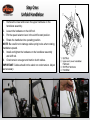
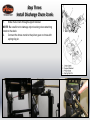
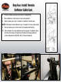
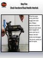
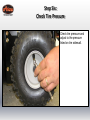
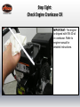
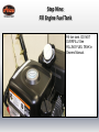
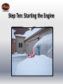
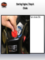
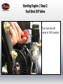
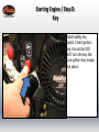
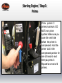
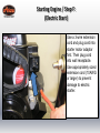
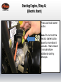
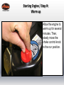
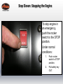
Quick Start Guide
Sno-Tek 28E (920403 s/n 35000 - 74999)
•
•
•
•
•
•
•
•
•
•
•
Step 1: Unfold Handlebar
Step 2: Install Discharge Chute
Step 3: Install Discharge Chute Crank
Step 4: Install Remote Deflector Cable
Step 5: Check Function of Dual Handle Interlock
Step 6: Check Tire Pressure
Step 7: Check Auger Gearcase Oil
Step 8: Check Engine Crankcase Oil
Step 9: Fill Engine Fuel Tank
Step 10: Start Engine
Step 11: Stop Engine
READ AND UNDERSTAND ALL INSTRUCTION, WARNING, AND DANGER LABELS.
IMPORTANT: READ OPERATOR’S MANUAL AND ENGINE MANUAL
THOROUGHLY AND FOLLOW THE IMPORTANT SAFE OPERATION PRACTICES
BEFORE OPERATING.
Step One:
Unfold Handlebar
1.
Remove the lower and loosen the upper hardware on the
handlebar assembly.
2. Loosen the hardware on the shift rod.
3. Put the speed selector lever in the sixth forward position.
4. Rotate the handlebar into operating position.
NOTE: Be careful not to damage cable spring hooks when rotating
handlebar upward.
5. Install and tighten the hardware on the handlebar assembly
and shift rod.
6. Check tension on auger and traction clutch cables.
IMPORTANT: Cables should not be slack nor under tension. Adjust
as necessary.
Step Two:
Install Discharge Chute
1.
2.
Remove mounting hardware from the bottom of the chute
pedestal mount.
Install discharge chute over opening in the auger housing and
secure pedestal to auger housing with hardware removed
above.
Step Three:
Install Discharge Chute Crank
1.
Slide chute crank through support bracket.
NOTE: Be careful not to damage nylon bushing when attaching
crank to the dash.
2.
Connect the chute crank to the pinion gear on chute with
spring clip pin.
Step Four:
Install Remote Deflector Cable
1.
2.
3.
4.
5.
Slide cable through clip on top of discharge chute pedestal
Bend clip closed around cable.
Using the wire hook attached to the deflector cable, hook cable
to discharge chute crank.
Pull rubber seal cap away from snap fitting.
Install snap fitting into cable bracket’s mounting hole located
under the dash.
Step Four: Install Remote
Deflector Cable Cont.
6. Position rubber seal cap over the top of snap fitting.
7. Move deflector control lever to rear most position.
8. Attach cable eye to pin on bottom of deflector control lever.
NOTE: Hold down chute deflector cap, if needed, for more cable slack.
9. Secure cable eye to control lever with washer and hairpin.
10. Test controls to be sure deflector works properly. If deflector does
not follow full range of travel See Remote Discharge Deflector
Control Adjustment (920402, 403) of Owners Manual.
Step Five:
Check Function of Dual Handle Interlock
Without the engine
running, press down
(engage) both clutch
levers. Release
attachment clutch lever.
Attachment clutch should
remain engaged until
traction clutch lever is
released, then both
clutches must disengage.
If they do not, contact your
dealer for repairs.
Step Six:
Check Tire Pressure
Check tire pressure and
adjust to the pressure
listed on tire sidewall.
Step Seven:
Check Auger Gearcase Oil
Check oil level in auger
gearcase
(see Check Auger
Gearcase in Owners
Manual).
Step Eight:
Check Engine Crankcase Oil
IMPORTANT: The engine
is shipped with 5W-30 oil
in crankcase. Refer to
engine manual for
detailed instructions.
Step Nine:
Fill Engine Fuel Tank
Fill fuel tank. DO NOT
OVERFILL! See
FILLING FUEL TANK in
Owners Manual.
Step Ten: Starting the Engine
Starting Engine / Step A:
Choke
Turn choke ON.
Starting Engine / Step B:
Rocker Switch
Push rocker switch
to RUN position.
Starting Engine / Step C:
Fuel Shut Off Valve
Turn fuel shut off
valve to “ON” position.
Starting Engine / Step D:
Key
Install safety key
switch. Insert ignition
key into slot but DO
NOT turn the key. Be
sure ignition key snaps
into place.
Starting Engine / Step E:
Prime
Prime system: 3
primes maximum. DO
NOT over prime
system. Make sure you
cover the vent hole
before the primer is
compressed. Hold the
primer bulb in the
compressed position for
one full second each
time you press it.
Repeat for a total of 3
primes.
Starting Engine / Step F:
(Manual Start)
Grasp rope handle. Pull
slowly until resistance
is felt, then pull rope
firmly and quickly to
start engine and avoid
kickback.
Starting Engine / Step F:
(Electric Start)
Use a 3-wire extension
cord and plug cord into
starter motor adaptor
first. Then plug cord
into wall receptacle.
Use appropriately sized
extension cord (10AWG
or larger) to prevent
damage to electric
starter.
Starting Engine / Step G:
(Electric Start)
Press and hold starter
button.
Note: Do not hold the
electric starter button
down for more than 5
seconds. Wait at least
1 minute before
additional starting
attempts.
Starting Engine / Step H:
Warm up
Allow the engine to
warm up for several
minutes. Then,
slowly move the
choke control knob
to the run position.
Step Eleven: Stopping the Engine
To stop engine in
an emergency,
push the rocker
switch to the STOP
position.
Under normal
conditions:
1.
2.
Push rocker
switch to STOP
position.
Pull safety key
OUT.
Additional Resources
• Refer to Owners Manual and Engine Manual
• Contact Ariens Company
www.ariens.com
Phone: 920-756-4688
E-mail: [email protected]
• For issues concerning engine, please contact LCT
www.LCTUSA.com
Phone: 800-558-5402
2011 The Ariens Company. All rights reserved.