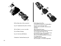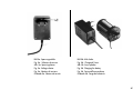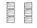
1
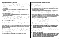
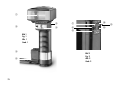
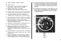
MECABLITZ 45 CL-4
Bedienungsanleitung
Gebruiksaanwijzing
Manuale istruzioni
Mode d’emploi
Operating instruction
Manual de instrucciones
Contents
ķ
1.
2.
2.1
2.2
2.3
2.3.1
2.3.2
2.3.3
2.4
3.
4.
5.
6.
6.1
6.2
6.3
7.
8.
8.1
8.2
8.3
9.
10.
11.
11.1
11.2
12.
13.
14.
40
Foreword . . . . . . . . . . . . . . . . . . . . . . . . . . . . . . . . . . . . . . . . . 40
Points worth knowing . . . . . . . . . . . . . . . . . . . . . . . . . . . . . . . . . 41
Special flash functions . . . . . . . . . . . . . . . . . . . . . . . . . . . . . . . . 41
Safety instructions . . . . . . . . . . . . . . . . . . . . . . . . . . . . . . . . . . . 43
Preparing the flashgun for use. . . . . . . . . . . . . . . . . . . . . . . . . . . 43
Attaching the flashgun to a camera . . . . . . . . . . . . . . . . . . . . . . . 43
Power supply . . . . . . . . . . . . . . . . . . . . . . . . . . . . . . . . . . . . . . . 43
Battery replacement . . . . . . . . . . . . . . . . . . . . . . . . . . . . . . . . . . 44
Exchanging the batteries. . . . . . . . . . . . . . . . . . . . . . . . . . . . . . . 44
Operation with the battery pack . . . . . . . . . . . . . . . . . . . . . . . . . 44
Operation with the mains unit . . . . . . . . . . . . . . . . . . . . . . . . . . . 44
Switching the flashgun on and off . . . . . . . . . . . . . . . . . . . . . . . . 44
TTL flash mode. . . . . . . . . . . . . . . . . . . . . . . . . . . . . . . . . . . . . . 44
Automatic flash mode. . . . . . . . . . . . . . . . . . . . . . . . . . . . . . . . . 45
Manual flash mode . . . . . . . . . . . . . . . . . . . . . . . . . . . . . . . . . . 46
Bounced flash . . . . . . . . . . . . . . . . . . . . . . . . . . . . . . . . . . . . . . 46
Bounced flash with activated secondary reflector . . . . . . . . . . . . . 46
Bounced flash in automatic and TTL flash modes. . . . . . . . . . . . . . 47
Bounced flash in manual flash mode . . . . . . . . . . . . . . . . . . . . . . 47
Winder mode . . . . . . . . . . . . . . . . . . . . . . . . . . . . . . . . . . . . . . 47
Fill-in flash in daylight . . . . . . . . . . . . . . . . . . . . . . . . . . . . . . . . 47
Fill-in flash in automatic mode. . . . . . . . . . . . . . . . . . . . . . . . . . . 47
Fill-in flash in manual mode . . . . . . . . . . . . . . . . . . . . . . . . . . . . 48
Fill-in flash in TTL mode . . . . . . . . . . . . . . . . . . . . . . . . . . . . . . . 48
Auto-check display. . . . . . . . . . . . . . . . . . . . . . . . . . . . . . . . . . . 48
Illumination and wide-angle diffuser . . . . . . . . . . . . . . . . . . . . . . 48
Exposure corrections . . . . . . . . . . . . . . . . . . . . . . . . . . . . . . . . . 49
Exposure correction in automatic flash mode . . . . . . . . . . . . . . . . 49
Exposure correction in TTL flash mode . . . . . . . . . . . . . . . . . . . . . 49
Care and maintenance . . . . . . . . . . . . . . . . . . . . . . . . . . . . . . . . 49
Technical data . . . . . . . . . . . . . . . . . . . . . . . . . . . . . . . . . . . . . . 49
Optional accessories . . . . . . . . . . . . . . . . . . . . . . . . . . . . . . . . . 50
Foreword
Congratulations on purchasing this METZ flashgun, and thank you for your
confidence in METZ equipment.
It is only natural that you should want to use your flashgun straight away.
However, it will be well worth your while to study these Operating
Instructions carefully beforehand to ensure that you can operate the flashgun
effectively and without any problems.
☞ Please also oppen the back cover page with the illustrations.
This flashgun can be used with:
• All cameras with a hot shoe in conjunction with the synch cable 45-54
(optional accessory).
• All cameras with synch connection in conjunction with the supplied synch
cable.
• System cameras
Optimal adaptation to your camera is achieved by using an SCA adapter.
The enclosed SCA 300/3002 table will indicate the adapter you require
for your particular camera model. This table also indicates the special flash
functions that can then be completed by the given system.
Brief survey of the operating functions:
Configuration and operating modes
• 45 CL-4 with synch cable:
Automatic flash mode, Ch. 4, Page 45.
Manual flash mode, Ch. 5, Page 46.
• 45 CL-4 with SCA 300/3002-adapter:
Automatic flash mode, Ch. 4, Page 45.
TTL-flash mode*, Ch. 3, Page 44.
Manual flash mode, Ch. 5, Page 46.
*Provided that the camera performs this function.
Point worth knowing
The mecablitz 45 CL-4 is available in two versions:
• mecablitz 45 CL-4-NC
(with NiCad battery and battery charger)
The NC version can be expanded to alkaline manganese battery operation
by way of the battery holder 45-39 (available as an optional extra).
• mecablitz 45 CL-4-BAT (for operation with alkaline manganese batteries,
batteries are not included)
The battery version can be upgraded to rechargeable NiCad battery operation by adding the B 45 charger set (= NiCad battery and battery charger)
Outstanding features:
• Universal, swivelling quadrolight reflector for bounced flash without having
to forgo the benefits of automatic exposure control.
• Secondary reflector that can be activated for front fill-in light with bounced
flash exposures.
• Wide-angle diffuser with automatic data display changeover.
• Automatic exposure control with a selection of 6 working apertures to easily resolve the problems associated with depth-of-field and to offer greater
creative scope regarding camera settings.
• Power-saving thyristor light output control, particularly in the close-up range, for shorter recycle times and a higher number of flashes from just one
battery charge
• Correct exposure confirmation (auto check) with a long display duration.
• Convenient calculator dial for all settings.
• Manual mode at full, half and quarter light output.
• Operation with winder cameras.
• Operating mode indicated by luminous display.
• SCA 300 dedicated system. Adapters (optional accessories) will match the
mecablitz with the special functions of different system cameras. Please
refer to the enclosed SCA 300/3002 table to establish which adapter is
required for the given camera. The table also lists the special flash functions which the system can then perform.
Special flash functions
when using an SCA 300 adapter:
• Flash-ready indication in the camera’s viewfinder.
• Correct exposure indication (auto check) in the camera’s viewfinder
A signal in the viewfinder of many cameras indicates correct exposure or
under-exposure of the film when in automatic or TTL flash mode.
• Automatic flash synch speed control
With most system cameras flash readiness causes the shutter speed to be
automatically changed from the adjusted mode to flash synch speed. On
some cameras slower adjusted shutter speeds are retained. The original
shutter speed is automatically readjusted on the camera as soon as the
flash-ready display has extinguished, or when the flashgun is switched off.
• TTL flash control
• Triggering control
The flash is not fired if, as a result of the aperture set on the lens in keeping
with the prevailing ambient light level, a shutter speed is adjusted on the
camera that equals or is faster than the flash synch speed. The picture is
then shot with the ambient light, thereby avoiding overexposure.
• First- or second-blind synchronization option
This mode offers two possibilities of flash synchronization:
- Either when the first blind of the focal plane shutter opens, or
- just before closure of the second blind.
The required synchronization is selected on the SCA adapter.
Synchronization with the secon shutter blind is valuable when a slow shutter speed has to be used to shoot a moving object that has its own source
of light.
• Autofocus measuring beam
The autofocus measuring beam is activated by the camera’s electronic
41
ķ
ķ
system as soon as the ambient light level is no longer sufficient for automatic focusing. The autofocus ermitter emits a striped pattern. If an SCA 300
autofocus adapter is used, only the autofocus measuring beam built into
the adapter is activated.
• Program auto flash mode
Some cameras merge in the „Program“ mode the ambient light with the
light emitted by the flashgun. The camera automatically adjusts a shutter
speed/aperture combination, and controls the flash in TTL mode.
Operation of the flash/camera combination thus becomes very simple.
when using an SCA 3002 adapter all SCA 300 functions can be performed, plus:
• TTL fill-in flash control
Some system cameras offer TTL fill-in flash control in addition to the standard TTL flash control mode. This operating mode is used for daylight
exposures to brighten up dense shadows and for shots against the light
(contre-jour). The camera’s, in conjunction with internal sensor measurement within the camera, ensures that the correct amount of flash light is
emitted to achieve a balanced exposure. The camera automatically performs the flash exposure correction that is necessary for fill-in flash shots.
• TTL flash exposure correction
There are certain photographic situations where the camera’s internal sensor can be deceived. This can be particularly the case with a dark subject
in front of a bright background (the subject is overexposed). To overcome
this problem in such a photographic situation an still achieve a correct eposure in the TTL flash mode, some cameras can influence the flash power of
the flashgun. All elements of an exposure are influenced by normal exposure corrections with the help of aperture or shutter-speed settings, change
of film speed or by the + correction on the camera. However, the overall
exposure can be retained with the help of the special exposure correction
function so that only the darker sections are brightened up by the flash.
Further details on this mode are given in the respective operating instructions for the adapter and camera.
• A-TTL flash control
42
(only with Canon SCA 3101/3102 Adapter)
A pre-flash is fired to supply the camera with additional distance data and
metered exposure values. As a result of these data the camera’s electronics
automatically adjusts the required shutter-speed/aperture-setting combination. The camera controls the amount of light emitted by the flashgun for
this purpose.
• Pre-flash to avoid red eyes
(only with Sigma SCA 3601 Adapter)
The red-eye effect is a physical phenomenon. It arises whenever a person,
against a relatively dark background, is looking straight into the camera
when the flash on the camera is fired. The light from the flash is reflected
by the blood vessels in the retina through the pupils an is recorded on the
film as red spots in the eyes-hence red eyes. The red-eye reduction facility
offers significant advantages in this respect. When this function ist adjusted
on the mecablitz a successsion of three visible weak flashes is fired before
the shutter is tripped, and prior to the measuring beam for the multi-sensor
(it possible with flash unit resp. camera); the pre-flashes are immediately
followed by the main flash. The light of these pre-flashes induces the pupils
to close, thereby substantially reducing the red-eye effect. This function is
available with all exposure programs. For further details please refer to the
operating instructions of the camera.
1. Safety instructions
2. Preparing the flashgun for use
• The flash unit is exclusively intended and approved for photographic use!
• Never fire a flash in the vicinity of flammable gases or liquids (petrol,
solvents, etc.) - DANGER OF EXPLOSION!
• Never take flash shots of car, bus or train drivers, or of motorcycle and
bicycle riders, whilst they are travelling. They could be blinded by the
light and cause an accident!
• Never fire a flash in the immediate vicinity of the eyes! Flash fired directly in front of the eyes of a person or animal can damage the retina and
lead to severe visual disorders - even blindness!
• Only use the approved power sources listed in the Operating
Instructions!
• Do not expose batteries to excessive heat, sunshine, fire and the like!
• Never throw exhausted batteries on to a fire!
• Exhausted batteries should be immediately removed from the flash unit!
Lye leaking out of spent batteries will damage the unit.
• Never recharge dry-cell batteries!
• Do not expose the flash unit or battery charger to dripping or splashing
water!
• Protect the flash unit from excessive heat and humidity! Do not store the
flash unit in the glove compartment of a car!
• Never place material that is impervious to light in front of, or directly on,
the reflector screen. The reflector screen must be perfectly clean when a
flash is fired. The high energy of the flash light will burn the material or
damage the reflector screen if this is not observed.
• Do not touch the reflector screen after a series of flash shots. Danger of
burns!
• Never disassemble the flashgun! DANGER: HIGH VOLTAGE!
• There are no components inside the flashgun that can be repaired by a
layperson.
2.1 Attaching the flashgun to a camera
The flashgun can only be operated with a synch cable a or the connecting
cables SCA 300 A1) or SCA 3000 C1) and an SCA-300/3002 adapter1) on
the camera.
1)(Optional accessories)
Be
sure
to
switch
off
the
mecablitz
by
its
main
switch
to mounting
☞ or removing the standard foot or SCA adapter. Beforeprior
mounting or
removing the flash unit, switch off both the camera and the flash unit!
Push adapter or 301 standard foot into the camera’s accessory shoe and
lock in place with the knurled nut.
An SCA-300 adapter or the 301 standard foot are connected to the flashgun
with the SCA 300 A 1) connecting cable.
An SCA-3002 adapter is connected to the flashgun with the SCA 3000 C 1)
connecting cable.
Mounting the flashgun:
• Fasten the camera bracket with the bracket screw to the camera’s tripod
bush. For medium- and large-format cameras we recommend the use of
the 70-35 bracket (optional accessory).
• Insert the camera bracket into the holder block of the bracket holder until it is audibly engaged.
• Secure the camera bracket with the locking screw.
• Connect the synch or SCA cable to the flashgun and camera or adapter.
2.2 Power supply
The flashgun can be operated with:
• Alkaline manganese batteries, size IEC LR 6 (AA-type) (only with BAT-version, otherwise optional extra)
• Metz NiCad battery pack 45-40 (only if NiCad is featured; otherwise
available as an optional accessory). A charger (see table 2, page 76) is
43
ķ
included with the flashgun if NiCad is featured).
• Power Pack P 50 (optional accessory)
2.3 Battery replacement
Press the two locking keys of the battery housing, and pull out of the flashgun
(fig. 4a). To return the battery housing press the two locking keys together
and press into the handle-mount grip of the flashgun until it audibly engages.
2.3.1 Exchanging the batteries
Press together the smooth locking keys of the dismantled battery housing
(only with BAT-version, otherwise optional extra) and remove the lid (fig. 4b).
Insert new batteries in conformity with the polarity symbols indicated in the
base of the housing. Return the lid and lock in again.
batteries must not be thrown into the domestic waste! Help keep
☞ Spent
the environment clean and discard spent batteries at corresponding
collecting points!
ķ
battery housing must not be fitted with NiCad batteries! The contacts
☞ The
of the battery housing are only intended for alkaline manganese batteries. The lower resistance of NiCad batteries means that more current can
flow, and this can damage the flashgun. The NiCad Battery Pack 45-40
has special contacts which do not allow the flow of high currents.
2.3.2 Operation with the battery pack
The NiCad battery should be charged for 5 hours before it is used for the first
time. The NiCad battery can be charged within the flashgun or externally.
The flashgun must NOT be switched on while the battery is
☞ Warning:
being charged within the flashgun!
The NiCad battery is discharged if the recycle time after a flash exceeds 60
seconds.
Adjust the correct mains voltage on the charger prior to charging. The voltage selector (fig. 5a) is located next to the plug and can be adjusted with a
small screwdriver.
The connection for the charger (fig. 5b) is in the base of the NiCad battery.
44
The adjoining pilot lamp lights up while charging is in progress.
The charging time for a completely exhausted NiCad battery is 5 hours. A
partly discharged NiCad battery requires a correspondingly diminished
charging time.
• To identify an exhausted battery: Push the knurled slide in the battery lid to
the black mark.
• To identify a charged battery: Push the knurled slide in the battery lid to the
white mark.
2.4 Switching the flashgun on and off
The flashgun is switched on with the main switch . The flashgun is permanently switched on when the switch is pushed to the top position, and the
operating light shines. Push the main switch to the bottom position to switch
off the flashgun.
3. TTL Flash Mode
(only with SCA adapter)
Perfect flash exposures can be shot in a simple manner in TTL mode.
The exposure readings in TTL mode are made by the sensor built into the
camera. This sensor measures the light reaching the film through the camera
lens. As soon as the film has been exposed by the correct amount of light, an
electronic control circuit within the camera transmits a stop signal to the
adapter (optional accessory), and the flash is instantly cut out.
The advantage of this flash mode is that all factors influencing the exposure
of the film (filters, change of aperture and focal length with zoom lenses,
extensions for close-ups, etc.) are automatically taken into account.
TTL flash mode is only possible with cameras that feature this func☞ The
tion. The flashgun must be fitted with a corresponding SCA adapter
(see SCA 3002 System Instructions and SCA Survey Table) for this purpose. A film must be loaded in the camera to test the TTL functions.
corrections may be necessary with pronounced differences
☞ Exposure
in contrast, for instance dark objects in snow (see Ch. 11, page 49).
Adjusting procedure for TTL flash mode:
• Adjust the camera according to the manufacturer’s operating instructions.
• Turn the adjusting knob for film speed until the white marker is positioned opposite the ISO film speed so that the distance range can be read off.
The film speed must also be set on the camera and, if necessary, on the
SCA adapter.
• Fit the flashgun with the appropriate SCA adapter and mount on the
camera.
• Switch on the flashgun with the main switch .
• Turn the selector dial to TTL.
The distance ranges can be directly read off the aperture calculator, or
taken from Table 3, page 77 .
check the range, the flash can only be fired by the camera and not
☞ To
by way of the manual firing botton on the flashgun (where possible
the camera should be adjustet to multiple exposure.
4. Automatik Flash Mode
In the automatic flash mode the photosensor measures the light reflected from
the subject. The flash is cut off as soon as sufficient light has been emitted for
correct exposure.
In this manner there is no need to calculate and set a new aperture when the
distance is changed, provided that the subject remains within the indicated
automatic flash range.
The photosensor of the flashgun must be directed at the subject, regardless of
the direction at which the main reflector is pointing. The photosensor has a
measuring angle of approx. 25°, and it only measures the actual amount of
light emitted by the flashgun.
Six working apertures are available in the automatic flash mode.
Adjusting procedure for the automatic flash mode:
Example:
Flash-to-subject distance: 5 m
Film speed: ISO 100/21°
• Adjust the camera according to the manufacturer’s operating instructions.
• Turn the adjusting knob for film speed until the white marker is positioned opposite the ISO film speed.
Under due consideration of the maximum flash range, a distance of 5 m
permits selection of the auto apertures f/8, f/5.6, f/4 and f/2.8.
• Switch on the flashgun with the main switch .
• Set the selector dial to one of the green identified auto apertures. The setting line assigns the adjusted f-stop with the corresponding maximum flash
range on the distance scale. The minimum flash-to-subject distance is
approx. 10% of the maximum flash range.
• Adjust the same aperture on the flashgun and the camera.
To achieve the shortest possible depth-of-field (as required in portraiture)
we recommend an aperture of f/2.8. For group shots where there can be
several rows of people behind each other, we recommend an aperture of
f/8.
• Wait for flash readiness - the green LED lights up.
subject should be within the middle third of the distance range.
☞ The
This gives the electronic control sufficient scope for compensation
should this be necessary.
There is a certain measure of overlap between the individual automatic apertures. As a result of this overlap it is always possible to place the subject within the middle third of the range.
with zoom lenses!
☞ CAUTION
Due to their design they can cause a loss of light in the order of up to
one f-stop. Furthermore, the effective aperture can also vary, depending upon the adjusted focal length. This must be compensated by
manually correcting the aperture setting on the flashgun!
45
ķ
ķ
5. Manual Flash Mode
6. Bounced Flash
In this mode the flashgun will emit its full power, provided that partial light
output (M1/2 - M1/4) has not been adjusted. The flashgun can be adapted
to the actual picture shooting situation by setting the corresponding aperture
on the camera.
If the displayed value does not coincide with the actual distance, then the
aperture and/or partial light output level (M1/2 and M 1/4) have to be
changed accordingly.
The decisive points for partial light output are:
• The distance to the subject
• The required aperture
• The ISO film speed
Adjusting procedure for the manual flash mode:
Example:
Flash-to-subject distance: 5 m
Film speed: ISO 100/21°
• Adjust the camera according to the manufacturer’s operating instructions.
• Turn the adjusting knob for film speed until the white marker is positioned opposite the ISO film speed.
• Switch on the flashgun with the main switch .
• Set the selector dial to M.
The aperture to be adjusted is indicated on the scale above the given flashto-subject distance.
a flash-to-subject distance of 5 m (as in our example), an aperture
☞ At
of f/8 has to be set on the camera. The adjusted aperture must be corrected when the wide-angle diffuser is used. The settings calculator
takes the wide-angle diffuser into account.
Photos shot with full frontal flash are easily recognizable by their harsh, dense shadows. This is often associated with a sharp drop of light from the foreground to the background.
This phenomenon can be avoided with bounced flash because the diffused
light will produce a soft and uniform rendition of both the subject and the
background. For this purpose the main reflector is turned in such a manner
that the flash is bounced back from a suitable reflective surface (e.g. ceiling
or walls of a room).
For this reason the main reflector can be turned vertically and horizontally.
The following are the vertical lock-in positions for bounced flash:
• 15°, 30°, 45°, 60°, 75° and 90° (simply tilt the reflector to the required
angle)
The head can be swivelled horizontally to the left and right by 180°, and
locks into position at 90° and 180°.
swivelling the reflector vertically, it is essential to ensure that it
☞ When
is turned by a sufficiently wide angle so that direct light can no longer
fall on the subject. Therefore, always tilt the reflector to at least the 60°
lock-in position.
The diffused light bounced back from the reflective surfaces results in a soft
illumination of the subject.
The reflecting surface must be white or a neutral colour, and it must not be
structured (e.g. wooden beams in the ceiling) as this could cast shadows. For
colour effects just select reflective surfaces in the required colour.
Use of the secondary reflector is advantageous to avoid disturbing dense
shadows with bounced flash, for instance under the eyes and nose of portraits.
6.1 Bounced flash with activated secondary reflector
The secondary reflector produces frontal fill-in light when the flash is
bounced.
46
use of the secondary reflector is only expedient with bounced
☞ The
flash.
Switch
turns the secondary reflector on and off.
When the secondary reflector is activated, 85% of the light will be emitted by
the main reflector, and approx. 15% by the secondary reflector. The quoted
percentages may vary somewhat when flash with partial light output is adjusted, and the secondary reflector switched on.
Light output can be reduced with a light reducing filter by approx. 40%. For
this purpose place the reducing filter over the secondary reflector and press
both sides firmly until the filter audibly clicks into position.
6.2 Bounced flash in automatic and TTL flash modes
It is advisable to check prior to the actual exposure whether the light is sufficient for the selected aperture. Please refer to Ch. 9, page 48, for the corresponding procedure.
6.3 Bounced flash in manual flash mode
The required camera aperture in the manual flash mode is best established
with an exposure meter. Observe the following rule of thumb if an exposure
meter is not available
guide number
Camera aperture = —————————
light distance x 2
to establish the guide value for the aperture that can then be varied by +1 fstop for the actual exposure.
7. Winder Mode
Definition:
The winder mode involves shooting a sequence of pictures at a rate of several
frames per second. The winder mode uses partial light output levels (M 1/40).
Up to 2 flashes per second can be fired in this mode.
Adjusting procedure to work in winder flash mode
• Adjust the camera according to the manufacturer’s operating instructions.
• Turn the adjusting knob for film speed until the white marker is positioned opposite the ISO film speed.
• Switch on the flashgun with the main switch .
• Set the selector dial to W.
• Wait for flash readiness - the green LED lights up.
The aperture to be set on the camera can be read off the scale, opposite the
flash-to-subject distance.
☞ Winder mode is only possible with a NiCad battery or Power Pack.
8. Fill-in Flash in Daylight
The mecablitz can also be used for fill-in flash in daylight to soften harsh shadows and lower the contrast, thereby producing a more balanced exposure
when shooting against the light. Various possibilities are open to the user for
this purpose.
8.1 Fill-in flash in automatic mode
Use the camera, or a hand-held exposure meter, to establish the required
aperture and shutter speed for a normal exposure. Ensure that the shutter
speed either equals, or is slower than, the fastest flash synch speed (varies
with the given camera model).
Example:
Established aperture = f/8; established shutter speed = 1/60 sec. Flash
synch speed of the camera, e.g. 1/100 sec. (see operating instructions for
47
ķ
the given camera).
The two established values for aperture and shutter speed can be set on the
camera because the camera’s shutter speed is slower than the camera’s flash
synch speed.
To maintain a balanced range of highlights, for instance in order to retain the
character of the shadows, it is advisable to select the automatic aperture on
the flashgun one setting lower than the aperture adjusted on the camera. In
the above example the camera was adjusted to f/8. Consequently, we advise
you to set an aperture of f/5.6 on the flashgun.
When shooting into the light, ensure that the backlight does not shine directly
onto the sensor as this will confuse the flashgun’s electronics!
8.2 Fill-in flash in manual mode
ķ
The partial light output levels can be used in manual flash mode to achieve
the required brightening effect of fill-in flash.
Complete illumination of shadow areas
Use the camera, or a hand-held exposure meter, to establish the required
aperture and set this value on the camera. The given range of the flashgun is
indicated on the calculator dial. If the distance to the subject is shorter than
the indicated flash range, then select a partial light output level to match the
distance.
Stepped brightening
Use the camera, or a hand-held exposure meter, to establish the required
aperture and adjust this value on the camera. To diminish the brightening
effect compared with full illumination of shadow areas, reduce the partial
light output level of the flashgun by one setting.
8.3 Fill-in flash in TTL mode
Some camera models automatically control fill-in flash when in program or
automatic modes. The manner of camera internal fill-in flash control varies
greatly between modern camera models, making it impossible to give a precise description of the individual adjusting procedures. These are normally
specified in the operating instructions for the given camera.
48
Shadows can also be brightened with a flashgun in TTL mode on cameras
that do not feature a special fill-in flash program or setting. In such cases the
effect of fill-in flash depends upon the characteristics of the camera’s TTL
metering system. Consequently, in many instances, it will be advisable to
adjust automatic mode for fill-in flash.
9. Auto-Check Display
The auto-check signal o.k. lights up only when the frame will be, or was,
correctly exposed in auto or TTL mode.
In this manner it is possible to manually fire a test flash while in auto mode so
that the correct aperture can be established beforehand. This is particularly
valuable with bounced (indirect) flash when reflection conditions are difficult
to judge.
A test flash cannot be fired in TTL flash mode. The test flash is triggered with
the manual firing button .
If the auto-check display o.k. remains dark after a test flash, then adjust the
next wider aperture, or diminish the distance to the reflection surface of the
subject, and then repeat the test flash.
The f-stop established in this manner must also be set on the camera.
the camera and the flashgun with photosensor in the same man☞ Hold
ner as for the actual shot.
10. Illumination and Wide-Angle Diffuser
The wide-angle diffuser widens the horizontal lighting angle from 62° to 65°,
and the vertical lighting angle from 42° to 60°.
The wide-angle diffuser is intended for use with focal lengths of less than
35 mm (for 24 x 36 mm), and less than 75 mm (for 6 x 6 cm).
The wide-angle diffuser automatically diminishes the maximum flash ranges.
11. Exposure Corrections
12. Care and Maintenance
The automatic exposure systems are based on a subject reflection factor of
25%, this being the average reflection factor for subjects shot with flash.
Dark backgrounds absorb a lot of light, while bright backgrounds reflect a
great deal of light (e.g. backlit scenes), thereby resulting in subject overexposure or underexposure, respectively.
Remove dust and grime with a soft dry cloth, or a silicon-treated cloth. Do
not use detergents as these may damage the plastic parts.
Forming the flash capacitor
The flash capacitor incorporated in the flashgun undergoes a physical change when the flashgun is not switched on for prolonged periods. For this reason it is necessary to switch on the flashgun for approx. 10 minutes every 3
months. The battery must supply sufficient power to light up the flash-ready
light within one minute after the flashgun was switched on.
11.1 Exposure correction in automatic flash mode
To compensate the above mentioned effect, the exposure can be corrected by
opening or stopping down the camera’s aperture. With a bright background
the sensor of the flashgun cuts out the flash too soon with the result that the
actual subject is too dark. With a dark background the flash is cut out too
late so that the actual subject is too bright.
background:
☞ Bright
Open the camera aperture by 1/2 to 1 f-stop
(e.g. from f/5.6 to f/4).
background:
☞ Dark
Close the aperture by 1/2 to 1 f-stop
(e.g. from f/8 to f/11).
11.2 Exposure correction in TTL flash mode
Many cameras feature an adjusting element for exposure corrections that
can also be used in TTL flash mode.
Please observe the corresponding explanations in the Operating Instructions
for the camera.
Here, exposure correction by changing the aperture on the lens is not possible. This is because the camera’s automatic exposure system will regard the
changed f–stop as a normal working aperture.
13. Technical Data
Guide numbers at ISO 100/21°:
For meter systems: 45; for feet systems: 148
6 auto working apertures at ISO 100/21°:
f/2.8 - f/4 - f/5.6 - f/8 - f/11 - f/16
Flash durations:
• approx. 1/300...1/20000 second
• In M mode approx. 1/300 second at full light output
• At 1/2 light output approx. 1/1000 second
• At 1/4 light output approx. 1/2500 second
• In winder mode approx. 1/10000 second
Photosensor measuring angle: approx. 25°
Colour temperature: approx. 5600 K
Film speed: ISO 25 to ISO 1000
Synchronization: Low-voltage thyristor ignition
Number of flashes:
50*...2000 NiCad battery
100*...2600 with alkaline-manganese batteries
140*...3600 with high-capacity alkaline-manganese batteries
(*with full light output)
49
ķ
ķ
Recycling time:
7 sec. (in M mode)...0.3 with NiCad battery
13 sec. (in M mode)...0.3 sec. with alkaline-manganese batteries
11 sec. (in M mode)...0.3 sec. with high-capacity alkaline-manganese batteries
Swivelling range and locking positions of zoom reflector:
Upwards: 15° 30° 45° 60° 75° 90°
Anti-clockwise 90° 180°
Clockwise
90° 180°
Dimensions (w x h x d), approx.
Flashgun 92 x 247 x 102 mm
Weight:
Flashgun without power sources:
approx. 680 g
Table 1: Guide numbers at maximum light output (Pag. 76)
Table 2: Chargers (Pag. 76)
Table3: Distances in TTL flash mode (Pag. 77)
3. . . 16 Distance range without wide-angle diffuser
2. . . 11 Distance range with wide-angle diffuser
These zable does not apply to bounced flash.
Included:
Flashgun, camera bracket, battery housing 45-39 (only with BAT-version,
otherwise optional extra), synch cable 45-47, wide-angle diffuser 45-42,
light reducing filter 45-44, Operating Instructions, SCA 300/3002 Table,
(additionally with NiCad flashguns: NiCad battery pack 45-40 and battery
charger, see table 2, page 76).
50
14. Optional accessories
and damage caused to the mecablitz due to the use of
☞ Malfunctions
accessories from other manufacturers are not covered by our guarantee!
• Adapter of the System SCA 300.
For flash with system cameras (see separate operating instructions). The
SCA 300 A connecting cable is additionally required.
• Adapter of the System SCA 3002
For flash with system cameras with digital data transmission of the SCA
function. Extended functional features compared with the SCA 300 System
(see separate Operating Instructions). The SCA 3000 C connecting cable is
additionally required.
• Bag 45-29 (Order No: 0004529)
for telephoto attachment 45-33.
• Battery holder 45-39
For alkaline manganese batteries.
• Battery charger set B 45 (Order No: 0012045)
NiCad battery and charger for subsequent conversion of the 45 CL-4
Battery model to NiCad battery operation.
• Bounce diffuser 60-33 (Order No: 0006033)
To soften heavy shadows with reflected light.
• Bracket adapter 45-35 (Order No: 004535)
For parallax correction of reflector and camera with close-ups and wideangle shots.
• Bracket adapter 60-28 (Order No: 0006028)
Similar to 45-35, except adjustable in height.
• Camera bracket 70-35 (Order No: 0007035)
To attach the flashgun to the side of the camera.
• Camera cable release 45-26 (Order No: 0004526)
The camera shutter can be tripped with the same hand that is holding the
flashgun. This frees the other hand for focusing.
• Electric shutter release 45-25 (Order No: 0004525)
As 45-26, except with switch for electric actuation.
• Ever-ready case 45-34 (Order No: 0004534)
for flashgun and accessories.
• Filter set 45-32 (Order No: 0004532)
Consists of a set of 4 colour effects filters and 1 clear filter to hold any
coloured foil.
• Light reducing filter set 45-28 (Order No: 0004528
Consists of three neutral density filters, and a transparent filter holder for
coloured foils.
• Mecalux 11 (Order No: 0000011)
Slave triggering unit. For optical, delay-free remote triggering of slave
flashguns by a camera-triggered flash. Responds also to infrared light
beam. Does not require batteries.
• Mecalux Holder 60-26 (Order No: 0006026)
To mount the Mecalux 11.
• Mecamat 45-46 (Order No: 0004546)
External sensor that significantly extends the application range of the
mecablitz. 11 auto apertures are available. „MANUAL“ provides 7 coordinated light output levels with 7 fixed flash durations. Built-in viewfinder
with parallax compensation for close-ups. Two measuring angles of 25°
and 12° for optimal measurement.
• NiCad battery pack 45-40 (Order No: 0004540)
• Power Pack P 50 (Order No: 0012950)
For a high number of flashes and short recycling times (approx. 300 fullpower flashes)
• Shoulder strap 50-31 (Order No: 0005031)
• Stabilizing set 30-28 (Order No: 0003028)
Ensures that the camera cannot be inadvertently turned on the bracket.
• Standard foot 301 (Order No: 0093014)
Used in conjunction with SCA 300 A for connection to camera hot shoe.
• Synch lead SCA 300 A (Order No: 0009305)
Cable to connect the flashgun to the adapter of the SCA 300 System.
• Synch lead SCA 3000 C (Order No: 0033003)
Cable to connect the flashgun to the adapter of the SCA 3000 System.
• Synch leads:
Coiled synch lead 45-49 (Order No: 0004549)
Coiled synch lead 45-54 for hot shoe (Order No: 0004554)
Synch lead 45-48, 1 m (Order No: 0004548)
Synch extension lead 60-53 (1.25 m) (Order No: 0006053)
Synch extension lead 60-54 (5 m) (Order No: 0006054)
• Telephoto attachment 45-33 (Order No: 0004533)
For flash shots with telelenses. Nearly doubles the guide number. Infrared
shots are also possible.
ķ
51
Ķ
ISO
25/15°
32/16°
40/17°
50/18°
64/19°
80/20°
100/21°
125/22°
160/23°
200/24°
250/25°
320/26°
400/27°
500/28°
650/29°
800/30°
1000/31°
ĸ
ń
ķ
ƴ
į
Leitzahl, No-guide, Richtgetal
Guide number, Numero guida, N°-Guia
[m]
[ft]
23
25
28
32
36
40
45
50
57
64
71
80
90
101
113
127
142
74
83
93
105
118
132
148
166
186
209
235
263
295
331
372
417
468
Tabelle 1: Leitzahlen bei maximaler Lichtleistung
Tableau 1: Nombres-guides pour niveau de puissance maximal
Tabel 1: Richtgetallen bij vol vermogen
Table 1: Guide numbers at maximum light output
Tabella 1: Numeri guida a potenza piena
Tabla 1: Número-guía con plena potencia de luz
76
Land, Pays, Country Ladegerät, chargeur, Laadapparaten,
Paese, País
charger, ricaricatore, cargador
Europe
Great Britain
USA / Canada
Australia
Japan
South Africa
New Zealand
Korea
Tabelle 2: Ladegeräte
Tableau 2: Chargeurs
Tabel 2: Laadapparaten
Table 2: Chargers
Tabella 2: apparecchi di ricarica
Table 2: Cargadores
729
723
728
722
730
402.12e
725
726
Kamera -Blende / Ouverture de l’appareil / camera-diafragma
Camera aperture / Diaframma della fotocamera / Diafragma de la cámara
ISO
Tabelle 3: Entfernungsbereich
Tableau 3: Portée
Tabel 3: Flitsbereiken
Table 3: Distance range
Tabella 3: Campo di utilizzo
Table 3: Gama de distancias
1,4
2
2,8
4
5,6
8
11
16
22
32
25/15°
50/18°
100/21°
200/24°
400/27°
800/30°
3......16
2......11
2......11
1,5...8
1,5...8
1......6
1......6
0,7...4
0,7...4
0,5...3
0,5...3
0,4...2
0,4...2
0,3...1,5
-
4......23
3......16
3......16
2......11
2......11
1,5...8
1,5...8
1......6
1......6
0,7...4
0,7...4
0,5...3
0,5...3
0,4...2
0,4...2
0,3...1,5
-
5......32
4......23
4......23
3......16
3......16
2......11
2......11
1,5...8
1,5...8
1......6
1......6
0,7...4
0,7...4
0,5...3
0,5...3
0,4...2
0,4...2
0,3...1,5
-
5......32
4......23
4......23
3......16
3......16
2......11
2......11
1,5...8
1,5...8
1......6
1......6
0,7...4
0,7...4
0,5...3
0,5...3
0,4...2
0,4...2
0,3...1,5
5......32
4......23
4......23
3......16
3......16
2......11
2......11
1,5...8
1,5...8
1......6
1......6
0,7...4
0,7...4
0,5...3
0,5...3
0,4...2
5......32
4......23
4......23
3......16
3......16
2......11
2......11
1,5...8
1,5...8
1......6
1......6
0,7...4
0,7...4
0,5...3
Ķ
ĸ
ń
ķ
ƴ
Entfernungsbereich / Portée / Flitsbereiken [m]
Distance range / Campo di utilizzo / Gama de distancias [m]
į
77
Bild 1
Fig. 1
Afb. 1
Grab. 1
78
Bild 2
Fig. 2
Afb. 2
Grab. 2
Reflektor / Réflecteur / Reflector / Riflettore
Sensor / Sensore
Schienenhalter / Support de barrette / Beugelhouder,
Bracket holder / Supporto staffa / Porta-regleta
Haltebock / Bloc d’attache / Vastzetblok /
Holder block / Blocco reggi-staffa / Zapata de sujeción
Anschluß Power Pack / Prise pour Power Pack / Aansluiting Power Pack /
Power Pack connection / Presa per Power Pack / Conexión Power Pack
Einstellmarke für Blendenvorwahl / Repère de réglage carré pour
la présélection du diaphragme / Instelmarkering voor diafragmavoorkeuze / Frame for preselection of aperture, Indice quadrato
per preselezionare i diaframmi / Indice para la preselección de
diafragma
Einstellknopf für Filmempfindlichkeit / Clef de réglage de la sensibilité / Instelknop voor filmvoeligheid / Film speed setting knob /
Pomello d’impostazione della sensibilità / Botón de ajuste de la
sensibilidad de película
Zweitreflektor / Réflecteur secondaire / Tweede reflector /
Secondary reflector / Parabola ausiliaria / Reflector adicional
Handauslösetaste / Bouton d’open-flash / Ontspanknop voor handbedie-
ning / Manual firing button / Scatto sincro manuale / Disparador manual
Blitzbereitschaftsanzeige / Témoin de fonctionnament /
Flitsparaataan-duiding / Flash range indicator / Indicazione pronto lampo / Indicador de disposición
Hauptschalter / Interrupteur général / Hoofdschakelaar / Main
switch / Interruttore principale / Interruptor principal
Belichtungskontrollanzeige / Témoin de contrôle d’exposition /
Aanduiding van de belichtingscontrol / Exposure o.k. /
Indicazione di controllo esposizione / Indicación de control de la
exposición
Synchronlkabelbuchse / Prise du cáble synchro / Aansluiting voor
flitskabel / Sync cord socket / Presa per cavetto sincro / Conexión
para cable sincro
Schalter für Zweitreflektor / Interrupteur réflecteur secondaire /
Schakelaar tweede reflector / Switch for secondary reflector /
Interruttore parabola ausiliaria / Interruptor reflector adicional
Bild 3
Fig. 3
Afb. 3
Grab. 3
79
➭
➭
➭
➭
Bild 4a: Batterie-bzw. Akku auswechseln
Fig. 4a : Remplacement des piles ou de l’accu
Afb. 4a: Batterij- c.q. accu verwisselen
Fig. 4a: Battery changing
Fig. 4a: Sostituzione delle batterie
Grabado 4a: Cambio de batería o pilas
80
Bild 4b: Batteriekorb öffnen
(nur bei BAT-Ausstattung sonst Sonderzubehör)
Fig. 4b : Ouverture du tiroir à piles
(seulement avec version BAT, sinon accessoire
optionnel)
Afb. 4b: Batterijkorf openen
(Alleen bij batterij-uitvoering anders als accessoire)
Fig. 4b: Opening the battery housing
(only with BAT-version, otherwise optional extra)
Fig. 4b: Apertura del box portabatterie
(solo con versio dell’accumulatore ne a batterie,
se no quale opzione)
Grabado 4b: Abrir el portapilas
(solo versión pilas, si no accesorio opcionale)
Bild 5a: Spannungswähler
Fig. 5a : Sélecteur de tension
Afb. 5a: Spanningskiezer
Fig. 5a: Voltage selector
Fig. 5a: Selettore di tensione
Grabado 5a: Selector de tensión
Bild 5b: Akku laden
Fig. 5b : Charge de l’accu
Afb. 5b: Accu opladen
Fig. 5b: Charging the battery
Fig. 5b: Carica dell’accumulatore
Grabado 5b: Carga de la batería
81
Ķ
Hinweis:
Im Rahmen des CE-Zeichens wurde
bei der EMV-Prüfung die korrekte
Belichtung ausgewertet.
ķ
SCA-Kontakte nicht berühren !
Note:
Within the framework of the CE approval symbol, correct exposure was
evaluated in the course of the electromagnetic compatibility test.
In Ausnahmefällen kann eine Berührung zur Beschädigung des Gerätes
führen.
In exceptional cases the unit can be
damaged if these contacts are touched.
ĸ
Remarque:
L’exposition correcte a été évaluée
lors des essais de CEM dans le
cadre de la certification CE.
Ne pas toucher les contacts du
SCA !
Il paut arriver que le contact avec
les doigts provoque la dégradation
de l’appareil.
ń
Opmerking:
In het kader de CE-markering werd
bij de EMV-test de correcte be-lichting bepaald.
SCA Contacten niet aanraken !
In uitzonderlijke gevallen kan aanraken leiden.
Do not touch the SCA contacts !
ƴ
Avvertenza:
Nell’ambito delle prove EMV per il
segno CE è stata valutata la corretta
esposizione.
Non toccate mai i contatti SCA !
In casi eccezionali il toccare può
causare danni all’apparecchio.
į
Atención:
El símbolo CE significa una valoración dae exposición correcta con la
prueba EMV (prueba de tolerancia
electromagnética).
No tocar los contactos SCA !
En algunos casos un contacto puede producir daños en el aparato.
Metz - Werke GmbH & Co KG • Postfach 1267 • D-90506 Zirndorf • [email protected] • www.metz.de
Consumer electronics
Metz. Always first class.
Photoelectronics
Plastics technology
Industrial electronics
703 47 0149.A2
Ķĸńķƴį