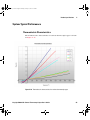
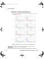
1
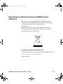
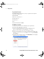
U2802A_UG.book Page 1 Monday, January 19, 2015 10:28 PM
Keysight U2802A 31-Channel
Thermocouple Input Device
User’s Guide
U2802A_UG.book Page 2 Monday, January 19, 2015 10:28 PM
U2802A_UG.book Page I Monday, January 19, 2015 10:28 PM
U2802A 31-Channel Thermocouple Input User’s Guide
I
U2802A_UG.book Page II Monday, January 19, 2015 10:28 PM
Notices
© Keysight Technologies 2008–2015
Warranty
No part of this manual may be reproduced in
any form or by any means (including electronic storage and retrieval or translation
into a foreign language) without prior agreement and written consent from Keysight
Technologies as governed by United States
and international copyright laws.
The material contained in this document is provided “as is,” and is subject to being changed, without notice,
in future editions. Further, to the maximum extent permitted by applicable
law, Keysight disclaims all warranties, either express or implied, with
regard to this manual and any information contained herein, including
but not limited to the implied warranties of merchantability and fitness for
a particular purpose. Keysight shall
not be liable for errors or for incidental or consequential damages in connection with the furnishing, use, or
performance of this document or of
any information contained herein.
Should Keysight and the user have a
separate written agreement with
warranty terms covering the material
in this document that conflict with
these terms, the warranty terms in the
separate agreement shall control.
Manual Part Number
U2802-90003
Edition
Edition 4, January 2015
Keysight Technologies
1400 Fountaingrove Parkway
Santa Rosa, CA 95403 USA
Safety Notices
Technology Licenses
The hardware and/or software described in
this document are furnished under a license
and may be used or copied only in accordance with the terms of such license.
Restricted Rights Legend
U.S. Government Restricted Rights. Software and technical data rights granted to
the federal government include only those
rights customarily provided to end user customers. Keysight provides this customary
commercial license in Software and technical data pursuant to FAR 12.211 (Technical
Data) and 12.212 (Computer Software) and,
for the Department of Defense, DFARS
252.227-7015 (Technical Data - Commercial
Items) and DFARS 227.7202-3 (Rights in
Commercial Computer Software or Computer Software Documentation).
II
C AUTI O N
A CAUTION notice denotes a hazard. It calls attention to an operating procedure, practice, or the like
that, if not correctly performed or
adhered to, could result in damage
to the product or loss of important
data. Do not proceed beyond a
CAUTION notice until the indicated
conditions are fully understood and
met.
WA R NI N G
A WARNING notice denotes a
hazard. It calls attention to an
operating procedure, practice, or
the like that, if not correctly performed or adhered to, could result
in personal injury or death. Do not
proceed beyond a WARNING
notice until the indicated conditions are fully understood and
met.
U2802A 31-Channel Thermocouple Input User’s Guide
U2802A_UG.book Page III Monday, January 19, 2015 10:28 PM
Safety Information
The following general safety precautions must be observed during all phases of this instrument. Failure to comply
with these precautions or with specific warnings elsewhere in this manual violates safety standards of design,
manufacture, and intended use of the instrument. Keysight Technologies assumes no liability for the customer’s
failure to comply with these requirements.
Safety Symbols
The following symbols indicate that precautions must be taken to maintain safe
operation of the instrument.
Direct current
Alternating current
Both direct and alternating current
Three-phase alternating current
Earth (ground) terminal
Protective conductor terminal
Frame or chassis terminal
Equipotentiality
On (Supply)
U2802A 31-Channel Thermocouple Input User’s Guide
III
U2802A_UG.book Page IV Monday, January 19, 2015 10:28 PM
Off (Supply)
Equipment protected throughout by double insulation or reinforced insulation
Caution, risk of electric shock
Caution, hot surface
Caution, risk of danger (See note.)
In position of a bi-stable push control
Out position of a bi-stable push control
IV
U2802A 31-Channel Thermocouple Input User’s Guide
U2802A_UG.book Page V Monday, January 19, 2015 10:28 PM
Regulatory Markings
The CE mark is a registered trademark of the European
community. This CE mark shows that the product complies with
all the relevant European legal directive.
ICES/NMB-001 indicates that this ISM device complies
with Canadian ICES-001.
The CSA mark is a registered trademark of the Canadian Standards Association. A CSA mark with the indicators "C" and "US"
means that the product is certified for both the U.S. and Canadian
markets, to the applicable American and Canadian standards.
The C-tick mark is a registered trademark of the Spectrum Management Agency of Australia. This signifies compliance with the
Australian EMC Framework regulations under the terms of the
Radio Communications Act of 1992.
This product complies with the (2002/96/EC) marking
equipment. The affixed product label indicates that you must not
discard this electrical/electronic product in domestic household
waste.
U2802A 31-Channel Thermocouple Input User’s Guide
V
U2802A_UG.book Page VI Monday, January 19, 2015 10:28 PM
General Safety Information
WA R NI N G
C AUTI O N
VI
• Do not use the device if it is damaged. Before you use the device,
inspect the case. Look for cracks or missing plastic. Do not operate the
device around explosive gas, vapor or dust.
• Do not apply more than the rated voltage (as marked on the device)
between terminals, or between terminal and external ground.
• Always use the device with the cables provided.
• Observe all markings on the device before connecting to the device.
• Turn off the device and application system power before connecting to
the I/O terminals.
• When servicing the device, use only specified replacement parts.
• Do not operate the device with the removable cover removed or
loosened.
• Do not connect any cables and terminal block prior to performing
self-test process.
• Use only the power adapter supplied by the manufacturer to avoid any
unexpected hazards.
• Do not load the input and output terminals above the specified
operating limits. Input terminals should not exceed ±10 V with respect
to the module ground. Applying excessive voltage or overloading the
device will cause irreversible damage to the circuitry.
• Applying excessive voltage or overloading the input terminal will
damage the device permanently.
• If the device is used in a manner not specified by the manufacturer, the
protection provided by the device may be impaired.
• The U2802A can only be used with U2355A or U2356A DAQs and used
with the SCSI cables provided.
• Always use dry cloth to clean the device. Do not use ethyl alcohol or
any other volatile liquid to clean the device.
• Do not permit any blockage of the ventilation holes of the device.
U2802A 31-Channel Thermocouple Input User’s Guide
U2802A_UG.book Page VII Monday, January 19, 2015 10:28 PM
Waste Electrical and Electronic Equipment (WEEE) Directive
2002/96/EC
This instrument complies with the WEEE Directive (2002/96/EC) marking
requirement. This affixed product label indicates that you must not discard this
electrical/electronic product in domestic household waste.
Product Category:
With reference to the equipment types in the WEEE directive Annex 1, this
instrument is classified as a “Monitoring and Control Instrument” product.
The affixed product label is shown as below:
Do not dispose in domestic household waste
To return this unwanted instrument, contact your nearest Keysight office, or visit:
http://www.keysight.com/environment/product
for more information.
U2802A 31-Channel Thermocouple Input User’s Guide
VII
U2802A_UG.book Page VIII Monday, January 19, 2015 10:28 PM
Environmental Conditions
The table below shows the general environmental requirements for the product.
VIII
Environmental Conditions
Requirements
Temperature
Operating temperature from 0 °C to +55 °C
Humidity
Relative humidity at 50% to 85% RH (Non-condensing)
Altitude
Altitude up to 2000 meters
Storage compliance
–40 °C to +70 °C
U2802A 31-Channel Thermocouple Input User’s Guide
U2802A_UG.book Page IX Monday, January 19, 2015 10:28 PM
In This Guide...
1
Getting Started
This chapter introduces the new Keysight U2802A 31- channel
thermocouple input device and provides quick start information. It
also provides product outlook, installation configuration and
troubleshooting guide.
2
Features and Functions
This chapter contains details of the product features, applications,
system overview and theory of operation. From this chapter, you
will understand the Keysight U2802A 31- channel thermocouple
input system overview and functionality of this device.
3
Pin Configurations and Assignments
This chapter described the Keysight U2802A 31- channel
thermocouple input device pin configurations and connector pinout
for user’s reference.
4
Product Specifications
This chapter specifies the environmental conditions,
characteristics, and specifications of the Keysight U2802A
31- channel thermocouple input device. It also covers the system
accuracy, typical performance and guidelines to make accurate
temperature measurements.
5
Calibration
This chapter contains the calibration information and factory
restore calibration procedure for the Keysight U2802A 31- channel
thermocouple input device.
U2802A 31-Channel Thermocouple Input User’s Guide
IX
U2802A_UG.book Page X Monday, January 19, 2015 10:28 PM
Declaration of Conformity (DoC)
The Declaration of Conformity (DoC) for this instrument is
available on the Web site. You can search the DoC by its product
model or description.
http://www.keysight.com/go/conformity
X
U2802A 31-Channel Thermocouple Input User’s Guide
U2802A_UG.book Page 1 Monday, January 19, 2015 10:28 PM
Contents
Notices II
Safety Information III
Environmental Conditions VIII
In This Guide... IX
Declaration of Conformity (DoC) X
1 Getting Started
Introduction to Keysight U2802A 31-Channel Thermocouple Input 6
Product Overview 7
Standard Purchase Items Checklist 10
Installations and Configurations 11
IVI-COM Drivers 12
2 Features and Functions
Features 18
Applications 19
System Overview 20
Theory of Operation 21
3 Pin Configurations and Assignments
Pin Configurations 30
Connector Pinout 36
4 Product Specifications
General Specifications 40
Product Characteristics 41
System Accuracy Specifications 43
System Typical Performance 49
Making Accurate Temperature Measurements 51
Contents 1
U2802A_UG.book Page 2 Monday, January 19, 2015 10:28 PM
5 Calibration
Calibration Information 54
Zeroing Function 54
Restore Factory Calibration 55
Contents 2
U2802A_UG.book Page 3 Monday, January 19, 2015 10:28 PM
List of Figures
Figure 2-1 System overview of U2802A with DAQ 20
Figure 2-2 System functionality block diagram for U2802A 21
Figure 2-3 Functional block diagram for U2802A 22
Figure 2-4 Functional block diagram for thermocouple mode in U2802A 23
Figure 2-5 Floating signal source configuration in U2802A 24
Figure 2-6 Ground-referenced and differential signal sources configuration in
U2802A 25
Figure 3-7 U2802A pin assignment 30
Figure 3-8 Connector 1 pin assignment for U2355A and U2356A 36
Figure 3-9 Connector 2 pin assignment for U2355A and U2356A 37
Figure 4-10 Thermoelectric characteristics for various thermocouple types 49
Figure 4-11 U2802A measurement accuracy plot for various thermocouples
type 50
Contents 3
U2802A_UG.book Page 4 Monday, January 19, 2015 10:28 PM
List of Tables
Table 4-1 U2802A measurement accuracy with U2355A or U2356A, at 23 °C ± 5 °C,
with different number of averaging points. 43
Table 4-2 U2802A measurement accuracy with U2355A, at 0 to 18 °C and 28 to 45 °C,
with different number of averaging points. 44
Table 4-3 U2802A measurement accuracy with U2356A, at 0 to 18 °C and 28 to 45 °C,
with different number of averaging points. 45
Contents 4
U2802A_UG.book Page 5 Monday, January 19, 2015 10:28 PM
Keysight U2802A 31-Channel Thermocouple Input
User’s Guide
1
Getting Started
Introduction to Keysight U2802A 31-Channel Thermocouple Input 6
Product Overview 7
Product Outlook 7
Product Dimensions 9
Standard Purchase Items Checklist 10
Installations and Configurations 11
IVI-COM Drivers 12
This chapter introduces the new Keysight U2802A 31- channel
thermocouple input device and provides quick start information. It also
provides product outlook, installation configuration and troubleshooting
guide.
U2802A_UG.book Page 6 Monday, January 19, 2015 10:28 PM
1
Getting Started
Introduction to Keysight U2802A 31-Channel Thermocouple Input
The Keysight U2802A 31- channel thermocouple input is a thermocouple
input device that functions to convert low input voltage signal
(< ±100 mV) from a thermocouple into an output voltage range suitable for
data acquisition (DAQ) device (± 10 V).
The Keysight U2802A thermocouple signal conditioner is to be used in
conjunction with the U2355A or U2356A model DAQ to enable
temperature measurements using thermocouples.
It works as a standalone device attached to a single DAQ. The U2802A
thermocouple device is connected to the modular DAQ via SCSI cables.
Keysight U2802A accepts eight standard thermocouple types defined in the
NIST ITS- 90 Thermocouple Database, which are Type B, E, J, K, N, R, S
and T.
It is ideal for a broad variety of temperature and voltage measurement
applications in education, industrial and scientific environments. The
U2802A comes with an on- board EEPROM features. Hence, it allows user
to store calibration data in volatile memory. Therefore, the U2802A is
robust, cost- effective, and user friendly device.
For detailed product specifications, please refer to “General Specifications”
on page 40.
6
Keysight U2802A 31-Channel Thermocouple Input User’s Guide
U2802A_UG.book Page 7 Monday, January 19, 2015 10:28 PM
Getting Started
1
Product Overview
Product Outlook
Top View
Connector 1
Connector 2
DetachableCover
Front View
Railing Guide
Strain Release Assembly
U2802A
31-Channel Thermocouple Input
Footer
Keysight U2802A 31-Channel Thermocouple Input User’s Guide
7
U2802A_UG.book Page 8 Monday, January 19, 2015 10:28 PM
1
Getting Started
Side View
Ventilation
Holes
Bottom View
8
Keysight U2802A 31-Channel Thermocouple Input User’s Guide
U2802A_UG.book Page 9 Monday, January 19, 2015 10:28 PM
Getting Started
1
Product Dimensions
Top View
Front View
U2802A
31-Channel Thermocouple Input
Keysight U2802A 31-Channel Thermocouple Input User’s Guide
9
U2802A_UG.book Page 10 Monday, January 19, 2015 10:28 PM
1
Getting Started
Standard Purchase Items Checklist
Inspect and verify that you have all the following items upon standard
purchase of U2802A 31- channel thermocouple input device. If there are
missing items, contact the nearest Keysight Sales Office.
✔ Keysight U2802A 31- channel thermocouple input device
✔ Power supply splitter
✔ Two 68- pin SCSI cables (1 m)
✔ One J- type thermocouple
✔ Keysight USB Modular Products and Systems Quick Start Guide
✔ Keysight USB Modular Products and Systems Product Reference
DVD- ROM
✔ Keysight Automation- Ready CD- ROM (contains the Keysight IO Libraries
Suite)
✔ Certificate of Calibration
10
Keysight U2802A 31-Channel Thermocouple Input User’s Guide
U2802A_UG.book Page 11 Monday, January 19, 2015 10:28 PM
Getting Started
1
Installations and Configurations
The U2802A is used in conjunction with the U2355A or U2356A DAQ. If
you are using the U2300A Series with the Keysight Measurement Manager,
follow the step- by- step instructions as stated in the Keysight USB Modular
Products and Systems Quick Start Guide.
N O TE
You need to install IVI-COM driver before using the U2300A Series with Keysight
VEE, LabVIEW or Microsoft Visual Studio.
Keysight U2802A 31-Channel Thermocouple Input User’s Guide
11
U2802A_UG.book Page 12 Monday, January 19, 2015 10:28 PM
1
Getting Started
IVI-COM Drivers
The Keysight IVI- COM drivers simplify instrument control when you are
working in a COM- compatible environment. IVI- COM allows you to
programmatically control your instrumentation and make measurements
while providing a greater degree of instrument interchangeability and code
reuse. The Keysight IVI- COM drivers support the use of IntelliSense for
even greater ease- of- use within a Microsoft development environment.
The Keysight IVI- COM driver supports all Keysight Series DAQs. The
Keysight Firmware Revision: A.2006.10.10 is the minimum revision
required for full driver functionality.
An IVI- COM driver can program a particular set of instrument models. It
implements an instrument- specific interface tuned to the capabilities of
those models. The driver may also implement an IVI class- compliant
interface which implements a limited set of functionality common to all
instruments of the class. Instrument class- compliant interfaces are defined
by the IVI Foundation. The application writer must choose whether to use
the instrument- specific interface or the class- compliant interface.
The IVI inherent capabilities, through the IIviDriver interface, are available
in both the instrument- specific interface and class- compliant interface.
The general programming techniques are also the same.
Choosing Instrument-Specific Interface
With this interface, you have the benefit of full access to the instrument's
capabilities. All capabilities in the class- compliant interface are also
covered by the instrument- specific interface, but you will find some
capabilities in the instrument- specific interface that are not available
through the class- compliant interface. You may also see some performance
enhancements, as the driver can be tuned to use efficient programming
methods for that particular instrument.
Choosing Class-Compliant Interface
By limiting your program to the class- compliant interface, you have the
potential advantage of syntactic interchangeability. Hence, another
IVI- COM driver (and instrument) which supports the same class could be
substituted for the original driver, if the prior IVI- COM driver supports all
the capability groups used in the original driver. In this case, the
12
Keysight U2802A 31-Channel Thermocouple Input User’s Guide
U2802A_UG.book Page 13 Monday, January 19, 2015 10:28 PM
Getting Started
1
application will compile, link, and execute without error. The test results,
however, may be quite different because different instruments measure
and generate signals differently. For more information on class- compliant
interfaces and capability groups, visit www.ivifoundation.org.
Using Class-Compliant Interface
Generally, you gain no advantage from using class- compliant interface over
using just the instrument- specific interface. However, if you can isolate the
usage of the instrument- specific interface, you may see some advantages.
Replacing the IVI- COM driver then involves fixing the syntactic
incompatibilities in the isolated code.
IVI- COM drivers will be provided to users. The drivers can also be used in
a variety of development environments. For more information on IVI, visit
www.ivifoundation.org.
Below are the IVI- COM drivers provided:
✔ KeysightVEE support through COM mechanism using IVI- COM
✔ Visual Basic 6 support through COM mechanism using IVI- COM
✔ C++ support through COM mechanism using IVI- COM
✔ Visual Basic 7 support through COM Interop mechanism using IVI- COM
✔ C# support through COM Interop mechanism using IVI- COM
✔ National Instruments LabVIEW support through COM mechanism using
IVI- COM
The Keysight firmware update utility is provided to allow users to update
firmware on instruments. Update is made available through Keysight
Developer Network (ADN) website:
www.keysight.com/find/adn
Keysight U2802A 31-Channel Thermocouple Input User’s Guide
13
U2802A_UG.book Page 14 Monday, January 19, 2015 10:28 PM
1
Getting Started
Programming Environments
An IVI- COM driver works well in a variety of application development
environments (ADEs) below:
✔ Keysight VEE
✔ Microsoft® Visual Basic® 6
✔ Visual Studio C++
✔ Visual Basic 7
✔ C#
✔ National Instruments LabVIEW
IVI-COM Driver Installation
1 Verify that your PC meets the minimum system requirements.
2 Close all other applications on your PC.
3 Insert the Keysight USB Modular Products and Systems Product
Reference DVD- ROM into the DVD- ROM drive of your PC.
4 Wait for a few seconds for the auto- run window to appear.
5 If the auto- run window does not appear automatically, click Start > Run,
then type <drive>:\Autorun.exe, where <drive> is your DVD- ROM
drive alphabet.
6 When the auto- run window appears, click Software Driver on the Keysight
Modular Products Installation Menu.
14
Keysight U2802A 31-Channel Thermocouple Input User’s Guide
U2802A_UG.book Page 15 Monday, January 19, 2015 10:28 PM
Getting Started
1
7 Click IVI-COM to open the IVI- COM Driver Installation Menu.
8 Check on the U2300A Series and click Install and wait for the
Installation Dialog to appear.
9 When the Installation Dialog appears, click Next to begin the IVI Driver
installation.
10 Read the License Agreement(s). To accept the terms, click on the radio
button labeled I accept the terms in the License Agreement then click Next to
continue.
11 When the Setup Type dialog box appears, as shown below, clicking Install
will install all features for your configuration in standard locations on
your PC.
Keysight U2802A 31-Channel Thermocouple Input User’s Guide
15
U2802A_UG.book Page 16 Monday, January 19, 2015 10:28 PM
1
Getting Started
12 If you choose a Custom setup, the Select Features dialog box will appear.
a Click on any feature in the list to see the feature’s description and
space requirement. It is recommended that you install the sample
programs if you plan to program with the IVI driver. However, you
may omit this recommendation to save space.
b Select the check box for each feature to be installed. Clear the check
box to omit the feature selection.
c Click Next.
16
1
When the Ready to Install dialog box appears, click Install to confirm your
choices and begin copying files.
2
When the Complete dialog box appears, click Finish.
Keysight U2802A 31-Channel Thermocouple Input User’s Guide
U2802A_UG.book Page 17 Monday, January 19, 2015 10:28 PM
Keysight U2802A 31-Channel Thermocouple Input
User’s Guide
2
Features and Functions
Features 18
Applications 19
System Overview 20
Theory of Operation 21
Functionality of the System 21
Functional Block Diagram 22
This chapter contains details of the product features, applications,
system overview and theory of operation. From this chapter, you will
understand the Keysight U2802A 31- channel thermocouple input system
overview and functionality of this device.
U2802A_UG.book Page 18 Monday, January 19, 2015 10:28 PM
2
Features and Functions
Features
The U2802A Thermocouple Input conditioning device is complete with the
following features:
✔ Up to 31 differential input mode, or 31- single ended inputs in voltage
input mode. Each of the 31 channels can be configured as either
thermocouple or voltage input mode independently.
✔ ×97.673 gain setting for thermocouple input mode.
✔ Built- in thermistor for cold junction compensation (CJC).
✔ Built- in zeroing function to compensate for overall system offset errors
due to temperature drift.
✔ On- board EEPROM that allows user to restore back original factory
calibration data.
✔ Open thermocouple detection that allows user to check for any loose or
broken thermocouple connection before starting the data acquisition
process.
✔ Supports thermocouple type J, K, R, S, T, N, E, and B.
18
Keysight U2802A 31-Channel Thermocouple Input User’s Guide
U2802A_UG.book Page 19 Monday, January 19, 2015 10:28 PM
Features and Functions
2
Applications
The U2802A Thermocouple Input conditioning device is designed for
robust and demanding industrial applications. This product is suitable for
a wide range of applications in various fields inclusive of:
✔ Consumer electronics
• Product thermal analysis and characterization
• Environmental testing (Eg: Temperature Cycle)
• Process monitoring (Eg: Oven or solder reflow temperature
monitoring)
✔ Education
• Study of electronic cooling properties
• Material properties testing
✔ Container temperature profiling
✔ Appliances testing
Keysight U2802A 31-Channel Thermocouple Input User’s Guide
19
U2802A_UG.book Page 20 Monday, January 19, 2015 10:28 PM
2
Features and Functions
System Overview
Figure 2-1 System overview of U2802A with DAQ
The U2802A is essentially an amplifier module with a built- in temperature
sensor (thermistor). In thermocouple mode, the U2802A input channel is
used to amplify a differential voltage signal from a thermocouple (or any
low voltage signal source in the range of ±100 mV) by 100 times. The
signal is then output as an analog voltage in the ±10 V range into the DAQ
for conversion to a digital voltage reading.
The built- in thermistor in the U2802A can be read from Channel AI148 of
the U2300A series DAQ. The conversion from voltage to temperature for
this thermistor reading is done automatically by the AMM software. This
temperature reading will subsequently be used as the Cold Junction
Compensation (CJC) reference temperature.
With the correct voltage reading from the thermocouple and the CJC
temperature, the AMM software will then proceed to convert the
thermocouple voltage reading into a temperature reading, based on the
NIST ITS- 90 Thermocouple Database. This reading is then corrected for
both gain and offset errors due to the U2802A amplifiers using the
calibration constants stored in the U2802A EEPROM, which are read by
the PC via the DAQ's digital I/O lines.
The U2802A also has a built- in zeroing function, which allows users to
zero out the entire system's offset error, thus increasing the overall
accuracy of the system.
20
Keysight U2802A 31-Channel Thermocouple Input User’s Guide
U2802A_UG.book Page 21 Monday, January 19, 2015 10:28 PM
Features and Functions
2
Theory of Operation
Functionality of the System
Figure 2-2 System functionality block diagram for U2802A
13 Thermocouple voltage signals are detected at the U2802A thermocouple
inputs.
14 Signal is amplified with a gain of 97.673 by the U2802A.
15 The U2355A or U2356A DAQ converts the analog voltage signals to
digital voltage readings.
16 The AMM software (or IVI- COM driver) reads the Gain and Offset
calibration constants from the U2802A EEPROM via the DAQ DIO lines.
The digital voltage readings will be calibrated based on these constants.
17 The AMM software (or IVI- COM driver) converts the calibrated voltage
readings to temperature readings using the ITS- 90 conversion
polynomials.
Keysight U2802A 31-Channel Thermocouple Input User’s Guide
21
U2802A_UG.book Page 22 Monday, January 19, 2015 10:28 PM
2
Features and Functions
Functional Block Diagram
The block diagram below in Figure 2- 3 illustrates the key functional
components of the U2802A.
Figure 2-3 Functional block diagram for U2802A
22
Keysight U2802A 31-Channel Thermocouple Input User’s Guide
U2802A_UG.book Page 23 Monday, January 19, 2015 10:28 PM
Features and Functions
2
The major functional blocks of the U2802A module are:
• Analog input channel circuitry
• Cold junction sensor
• Digital control logic
• EEPROM
Analog input channel circuitry
The analog circuitry for each channel consists of an instrumentation
amplifier with a fixed gain of 97.673, a 4 Hz RC low- pass filter, and an
output buffer. The multiplexers at the input and output of each channel
allows each channel to be configured for three modes of operation as
listed below:
Thermocouple input mode:
In thermocouple mode, the thermocouples (or
any floating voltage source) should be connected to the TCn+ and TCn–
terminals as illustrated in Figure 2- 4. All TCn– terminals are internally
tied to module ground with a 10 MΩ resistor. The TCn+ and TCn– signals
are routed to the differential inputs of the instrumentation amplifier.
Differential voltage signals at the TCn+ and TCn– terminals are amplified,
filtered and driven out by single- ended output voltage to the
corresponding AI channel on Rear Connector 1.
Figure 2-4 Functional block diagram for thermocouple mode in U2802A
Keysight U2802A 31-Channel Thermocouple Input User’s Guide
23
U2802A_UG.book Page 24 Monday, January 19, 2015 10:28 PM
2
Features and Functions
Bypass mode: In bypass mode, the TCn+ input is routed directly to the
corresponding AI channel on Rear Connector 1. The single- ended signals
tied to TCn+ should be referenced to a GND pin, and not to the TCn–
input, as it is not directly connected to GND. The signal connection will
depend on the type of source used.
For floating signal sources, all input signals are connected to the ground
in the U2802A as illustrated in Figure 2- 3. However, it is not
recommended to tie ground- referenced signal sources in this manner. Any
potential differences between the signal source ground and the U2802A
ground could potentially induce excessive current to flow through the
ground wires causing the wires and module to be damaged.
Figure 2-5 Floating signal source configuration in U2802A
For ground- referenced signal sources and differential signal sources, the
configuration in Figure 2- 6 is recommended. Take note that the
corresponding DAQ channel will need to be configured as a DIFF input to
enable this type of connection.
24
Keysight U2802A 31-Channel Thermocouple Input User’s Guide
U2802A_UG.book Page 25 Monday, January 19, 2015 10:28 PM
Features and Functions
2
Figure 2-6 Ground-referenced and differential signal sources configuration in U2802A
Zero mode:
In zero mode, the positive and negative inputs of the
instrumentation amplifier are shorted together. The output of the
instrumentation amplifier is driven out to the corresponding AI channel.
The voltage measured in this mode corresponds to the offset voltage of
the channel. This voltage can be subtracted out of the subsequent
thermocouple mode measurements in order to increase the measurement
accuracy. Do take note that this mode only works for channels that have
been configured to be in the thermocouple mode. Channels configured for
bypass mode will not be affected when this mode is selected.
Each channel is equipped with an open thermocouple detection feature,
where the 10 MΩ resistor is tied to the +15 V power supply rail. This
feature can only be globally enabled or disabled for all channels,
regardless of the channel mode setting. When enabled, outputs of the
channels are set to thermocouple mode where the inputs are left
open- circuited. This causes the positive power supply rail voltage (above
+10 V) to be saturated up, indicating that the channel either has a broken
thermocouple or the thermocouple is not connected. For channels set to
bypass mode, channels with an open- circuited input will also be saturated
to the positive supply rail voltage.
Keysight U2802A 31-Channel Thermocouple Input User’s Guide
25
U2802A_UG.book Page 26 Monday, January 19, 2015 10:28 PM
2
Features and Functions
For bypass mode channels that are connected to valid voltage sources, the
10 MΩ pull- up resistor will cause additional current to flow through the
voltage source. However, this additional current measurement is small and
negligible for low impedance voltage sources.
For thermocouple mode channels connected to valid thermocouples, the
presence of the pull- up resistor introduces approximately 0.75 µA of
current through the thermocouple wires. This current introduces
additional errors when using thermocouples with high resistances, and the
measurement accuracy could be affected.
Cold junction sensor
A thermistor (RT1) is placed in between the screw terminals to measure
the temperature of the thermocouple junction for CJC. The output voltage
from the sensor is fed through a 4 Hz RC low- pass filter and buffered to
the AI148 pin on Rear Connector 1. The conversion from voltage to
temperature is done automatically by the AMM software.
Digital control
The digital control circuit consists of registers that controls the mode of
each channel and the open- thermocouple detect feature. The registers are
addressed and clocked via the digital I/O pins on Rear Connector 2. This
will be handled automatically by the AMM software.
EEPROM
The gain and offset calibration factors for each channel are stored in the
EEPROM during factory calibration and will be retrieved prior to taking
measurements. The EEPROM is tied to the digital I/O pins on Rear
Connector 2. The communication between the EEPROM and host PC is
automatically handled by the AMM software. In addition to the calibration
factors, the EEPROM stores the module ID, serial number, date of
calibration, which can also be retrieved before measurements are taken.
26
Keysight U2802A 31-Channel Thermocouple Input User’s Guide
U2802A_UG.book Page 27 Monday, January 19, 2015 10:28 PM
Features and Functions
2
Open Thermocouple Detection
The U2802A provides a built- in 10 MΩ resistor on each TC+ terminal,
which is pulled up to the internal +15 V power supply rail. This resistor
can be enabled or disabled via the digital I/O pins on Rear Connector 2.
When enabled, this 10 MΩ pull- up resistor and the 10 MΩ pull- down
biasing resistor will cause the output from any unconnected thermocouple
input channels to saturate to the maximum output voltage. The U2355A
and U2356A devices can read this saturated channel and detect that a
particular channel has an open thermocouple input.
Trigger, Counter, External Timebase, and Analog Output
The U2802A provides a direct access to the analog and digital trigger
lines, counter channels, external timebase input, and analog output
channels from the U2355A and U2356A devices. These lines are routed
directly from the Rear Connector 1 and 2 to the J60 screw terminal
connector. Please refer to pin description for Connector J60 on page 35.
Precautions should be taken when driving high slew rate and frequency
clocks into the Counter and External Timebase lines to avoid excessive
noise coupling into other analog and digital lines. If excessive coupling or
crosstalk is observed, clock output drive strengths and slew rates should
be lowered to reduce coupling while still maintaining proper digital
function.
Keysight U2802A 31-Channel Thermocouple Input User’s Guide
27
U2802A_UG.book Page 28 Monday, January 19, 2015 10:28 PM
2
28
Features and Functions
Keysight U2802A 31-Channel Thermocouple Input User’s Guide
U2802A_UG.book Page 29 Monday, January 19, 2015 10:28 PM
Keysight U2802A 31-Channel Thermocouple Input
User’s Guide
3
Pin Configurations and Assignments
Pin Configurations 30
Pin Assignments 30
Pin Description 31
Connector Pinout 36
This chapter described the Keysight U2802A 31- channel thermocouple
input device pin configurations and connector pinout for user’s
reference.
U2802A_UG.book Page 30 Monday, January 19, 2015 10:28 PM
3
Pin Configurations and Assignments
Pin Configurations
Pin Assignments
Figure 3-7 U2802A pin assignment
30
Keysight U2802A 31-Channel Thermocouple Input User’s Guide
U2802A_UG.book Page 31 Monday, January 19, 2015 10:28 PM
Pin Configurations and Assignments
3
Pin Description
Connector J71
Pin
Pin name
Description
1
TC1+
2
TC1–
In thermocouple mode, TCx+ and TCx– are the thermocouple differential
input. In voltage mode, single ended input at TCx+ and GND. TCx– is not
connected.
3
TC2+
TC input or voltage input (See TC1+/– description)
4
TC2–
5
TC3+
6
TC3–
7
TC4+
8
TC4–
9
TC5+
10
TC5–
11
TC6+
12
TC6–
13
TC7+
14
TC7–
15
TC8+
16
TC8–
17
GND
Module Ground
18
TC17+
TC input or voltage input (See TC1+/– description)
19
TC17–
20
TC18+
21
TC18–
22
TC19+
23
TC19–
24
TC20+
25
TC20–
26
TC21+
27
TC21–
TC input or voltage input (See TC1+/– description)
TC input or voltage input (See TC1+/– description)
TC input or voltage input (See TC1+/– description)
TC input or voltage input (See TC1+/– description)
TC input or voltage input (See TC1+/– description)
TC input or voltage input (See TC1+/– description)
TC input or voltage input (See TC1+/– description)
TC input or voltage input (See TC1+/– description)
TC input or voltage input (See TC1+/– description)
TC input or voltage input (See TC1+/– description)
Keysight U2802A 31-Channel Thermocouple Input User’s Guide
31
U2802A_UG.book Page 32 Monday, January 19, 2015 10:28 PM
3
32
Pin Configurations and Assignments
28
TC22+
29
TC22–
30
TC23+
31
TC23–
32
TC24+
33
TC24–
34
GND
TC input or voltage input (See TC1+/– description)
TC input or voltage input (See TC1+/– description)
TC input or voltage input (See TC1+/– description)
Module Ground
Keysight U2802A 31-Channel Thermocouple Input User’s Guide
U2802A_UG.book Page 33 Monday, January 19, 2015 10:28 PM
Pin Configurations and Assignments
3
Connector J50
Pin
Pin name
Description
1
GND
Module Ground
2
TC16–
TC input or voltage input (See TC1+/– description)
3
TC16+
4
TC15–
5
TC15+
6
TC14–
7
TC14+
8
TC13–
9
TC13+
10
TC12–
11
TC12+
12
TC11–
13
TC11+
14
TC10–
15
TC10+
16
TC9–
17
TC9+
18
GND
Module Ground
19
GND
Module Ground
20
GND
Module Ground
21
TC31–
TC input or voltage input (See TC1+/– description)
22
TC31+
23
TC30–
24
TC30+
25
TC29–
26
TC29+
27
TC28–
28
TC28+
29
TC27–
30
TC27+
TC input or voltage input (See TC1+/– description)
TC input or voltage input (See TC1+/– description)
TC input or voltage input (See TC1+/– description)
TC input or voltage input (See TC1+/– description)
TC input or voltage input (See TC1+/– description)
TC input or voltage input (See TC1+/– description)
TC input or voltage input (See TC1+/– description)
TC input or voltage input (See TC1+/– description)
TC input or voltage input (See TC1+/– description)
TC input or voltage input (See TC1+/– description)
TC input or voltage input (See TC1+/– description)
Keysight U2802A 31-Channel Thermocouple Input User’s Guide
33
U2802A_UG.book Page 34 Monday, January 19, 2015 10:28 PM
3
34
Pin Configurations and Assignments
31
TC26–
32
TC26+
33
TC25–
34
TC25+
TC input or voltage input (See TC1+/– description)
TC input or voltage input (See TC1+/– description)
Keysight U2802A 31-Channel Thermocouple Input User’s Guide
U2802A_UG.book Page 35 Monday, January 19, 2015 10:28 PM
Pin Configurations and Assignments
3
Connector J60
Pin
Pin name
Description
1
COUNT302_CLK
Directly connected to DAQ1
2
COUNT302_GATE
Directly connected to DAQ1
3
COUNT302_UPDOWN
Directly connected to DAQ1
4
COUNT302_OUT
Directly connected to DAQ1
5
EXTD_AI_TRIG
Directly connected to DAQ1
6
EXT_TIMEBASE
Directly connected to DAQ1
7
GND
Module Ground
8
AO_GND
Directly connected to DAQ1
9
AO_GND
Directly connected to DAQ1
10
GND
Module Ground
11
GND
Module Ground
12
GND
Module Ground
13
COUNT301_CLK
Directly connected to DAQ1
14
COUNT301_GATE
Directly connected to DAQ1
15
COUNT301_UPDOWN
Directly connected to DAQ1
16
COUNT301_OUT
Directly connected to DAQ1
17
EXTD_AO_TRIG
Directly connected to DAQ1
18
GND
Module Ground
19
AO201
Directly connected to DAQ1
20
AO202
Directly connected to DAQ1
21
AO_EXT_REF
Directly connected to DAQ1
22
EXTA_TRIG
Directly connected to DAQ1
23
GND
Module Ground
24
GND
Module Ground
1. Refer to the U2300A Series USB Multifunction Data Acquisition Devices User’s Guide for
connectivity
Keysight U2802A 31-Channel Thermocouple Input User’s Guide
35
U2802A_UG.book Page 36 Monday, January 19, 2015 10:28 PM
3
Pin Configurations and Assignments
Connector Pinout
Rear panel pinout for Connector 1
Figure 3-8 Connector 1 pin assignment for U2355A and U2356A
36
Keysight U2802A 31-Channel Thermocouple Input User’s Guide
U2802A_UG.book Page 37 Monday, January 19, 2015 10:28 PM
Pin Configurations and Assignments
3
Rear panel pinout for Connector 2
Figure 3-9 Connector 2 pin assignment for U2355A and U2356A
Keysight U2802A 31-Channel Thermocouple Input User’s Guide
37
U2802A_UG.book Page 38 Monday, January 19, 2015 10:28 PM
3
38
Pin Configurations and Assignments
Keysight U2802A 31-Channel Thermocouple Input User’s Guide
U2802A_UG.book Page 39 Monday, January 19, 2015 10:28 PM
Keysight U2802A 31-Channel Thermocouple Input
User’s Guide
4
Product Specifications
General Specifications 40
Product Characteristics 41
System Accuracy Specifications 43
Calculating System Accuracy 46
System Typical Performance 49
Making Accurate Temperature Measurements 51
This chapter specifies the environmental conditions, characteristics, and
specifications of the Keysight U2802A 31- channel thermocouple input
device. It also covers the system accuracy, typical performance and
guidelines to make accurate temperature measurements.
U2802A_UG.book Page 40 Monday, January 19, 2015 10:28 PM
4
Product Specifications
General Specifications
POWER CONSUMPTION
±12 VDC, 750 mA maximum
OPERATING ENVIRONMENT
• Operating temperature from 0 °C to 55 °C
• Relative humidity at 50% to 85% RH (non-condensing)
• Altitude up to 2000 meters
STORAGE COMPLIANCE
–40 °C to 70 °C
SAFETY COMPLIANCE
Certified with IEC 61010-1:2001/EN 61010-1:2001 (2nd Edition)
EMC COMPLIANCE
• IEC 61326-1:2002 / EN 61326-1:1997+A1:1998+A2:2001+A3:2003
• CISPR 11:1990/EN55011:1990 – Group 1, Class A
• CANADA: ICES-001: 2004
• Australia/New Zealand: AS/NZS CISPR11:2004
SHOCK & VIBRATION
Tested to IEC/EN 60068-2
IO CONNECTOR
• 2 x 68-pin female SCSI connector
• 2 x 34-pin screw terminal block
• 1 x 24 pin screw terminal block
DIMENSIONS (WxDxH)
159.7 mm x 254.2 mm x 40.5 mm
WEIGHT
1.036 KG
WARRANTY
Please refer to http://www.keysight.com/go/warranty_terms
• Three years for the product
• Three months for the product's standard accessories, unless otherwise specified
Please take note that for the product, the warranty does not cover:
• Damage from contamination
• Normal wear and tear of mechanical components
• Manuals
40
Keysight U2802A 31-Channel Thermocouple Input User’s Guide
U2802A_UG.book Page 41 Monday, January 19, 2015 10:28 PM
Product Specifications
4
Product Characteristics
GENERAL CHARACTERISTICS
Number of channels
Input voltage range for voltage mode
Input voltage (thermocouple mode)
Sampling rate for thermocouple mode
Sampling rate for overall module
Thermocouple types
31 differential and 1 CJC
±10 V (signal + common mode)
±100 mV
10 kSa/s total for all channels
500 kSa/s
J, K, R, S, T, N, E and B
INPUT SPECIFICATIONS
Accuracy (thermocouple mode)
Overall gain error
0.06% (23 °C ± 5 °C)
Overall offset error
15 µV (without zeroing) (23 °C ± 5 °C)
6 µV (with zeroing)
Nonlinearity
< 0.005% of Full Scale Range
System noise (rms)
Gain (x1)
Gain (x100)
100 µVrms
5 µVrms
Common mode rejection ratio (60 Hz)
Voltage mode
> 60 dB
Thermocouple mode
> 80 dB
Cold junction accuracy
±1.0 °C typical (23 °C ± 5°C)
±1.5 °C typical (0 °C to 18 °C, 28 °C to 55 °C)
INPUT CHARACTERISTICS
Bandwidth (voltage mode)
Bandwidth (thermocouple mode)
Keysight U2802A 31-Channel Thermocouple Input User’s Guide
> 500 kHz
4.0 Hz
41
U2802A_UG.book Page 42 Monday, January 19, 2015 10:28 PM
4
Product Specifications
Overvoltage protection*
TC Mode†
• Common mode: ±17 V (TC+ and TC– with
respect to GND)
• Differential mode: ±7 V (Differential voltage
between TC+ and TC–)
Bypass mode
• ±20 V (TC+ input with respect to GND)
Power Off Mode
• ±11 V (TC+, TC– input with respect to GND)
Input impedance
> 1 GΩ
Input bias current
±2.5 nA max
Input offset current
±1.5 nA max
Gain drift
60 ppm / °C max
Offset drift
1 µV / °C max
Filter cutoff frequency (–3 dB) (thermocouple
mode)
Filter type (thermocouple mode)
4.0 Hz
Low Pass RC Filter
OTHER FEATURES
Recommended warm up time
30 minutes
* The overvoltage protection levels specified above indicate the maximum voltage each input pin can
tolerate without resulting in any damages. However, prolonged exposure to these levels may affect
device safety and reliability. Hence, it should be avoided where possible.
† On the channels configured for thermocouple mode, the TC+ and TC– pins can tolerate up to ±17 V
of differential voltage for a few minutes. However, exceeding ±100 mV voltage range on these
channels can cause additional current to be drawn from the device’s power supply regulators,
which may damage the device if multiple channels are overdriven for prolonged periods. This
applies to the case where a voltage source is tied across the TCn+ and TCn– pin. Voltage sources
greater than ±100 mV should be tied to TCn+ and GND (floating source), or TCn+ and TCn+1+
(grounded source), and have the channels set for bypass mode. Refer to Figure 2-5 on page 24.
42
Keysight U2802A 31-Channel Thermocouple Input User’s Guide
U2802A_UG.book Page 43 Monday, January 19, 2015 10:28 PM
Product Specifications
4
System Accuracy Specifications
The Keysight U2802A thermocouple input measurement accuracy with the
U2355A and U2356A is as shown in Table 4- 1, Table 4- 2, and Table 4- 3.
N O TE
• Assume a ±1 °C error in the CJ measurement due to sensor error and temperature
gradient error in the accuracy numbers in Table 4-1, Table 4-2, and Table 4-3 below.
• Table 4-1, Table 4-2, and Table 4-3 are derived from the U2802A and DAQ input accuracy
specifications without including the thermocouple error. Refer to “Calculating System
Accuracy” on page 46 for calculation methodology.
Thermocouple Measurements Accuracy
(U2355A, U2356A @ 23 °C ± 5°C)
T/C
Type
B
ITS-90
Temperature
Range (°C)
Optimum
Measurement
Range(°C)
Without
averaging
50 points
averaging
500 points
averaging
(± °C)
(± °C)
(± °C)
Low
High
Low
High
0
1820
1100
1820
1.9
1.2
1.0
400
1100
4.4
2.5
2.0
1.7
1.6
1.6
E
–270
1000
–150
1000
–200
–150
2.4
2.3
2.3
J
–210
1200
–150
1200
1.6
1.5
1.5
–210
–150
2.7
2.6
2.5
–100
1200
1.5
1.4
1.4
–200
–100
2.7
2.6
2.6
–100
1300
1.5
1.3
1.3
–200
–100
3.0
2.7
2.6
300
1760
2.0
1.4
1.3
–50
300
5.0
3.1
2.6
400
1760
2.1
1.6
1.4
–50
400
4.5
2.8
2.4
–100
400
1.5
1.4
1.4
–200
–100
2.7
2.5
2.5
K
–270
1372
N
–270
1300
R
–50
1768
S
–50
1768
T
–270
400
Table 4-1 U2802A measurement accuracy with U2355A or U2356A, at 23 °C ± 5 °C, with
different number of averaging points.
Keysight U2802A 31-Channel Thermocouple Input User’s Guide
43
U2802A_UG.book Page 44 Monday, January 19, 2015 10:28 PM
4
Product Specifications
Thermocouple Measurements Accuracy
(U2355A @ 0 °C to 18 °C and 28 °C to 45 °C)
T/C
Type
B
E
J
K
N
R
S
T
ITS-90
Temperature
Range (°C)
Optimum
Measurement
Range(°C)
Without
averaging
50 points
averaging
500 points
averaging
(± °C)
(± °C)
(± °C)
Low
High
Low
High
0
1820
1100
1820
3.4
2.4
2.2
400
1100
7.5
3.6
2.2
–150
1000
2.7
2.6
2.5
–200
–150
3.8
3.6
3.6
–150
1200
2.5
2.4
2.4
–210
–150
4.2
4.0
3.9
–100
1200
2.9
2.8
2.8
–200
–100
4.3
4.0
3.9
–100
1300
2.6
2.5
2.5
–200
–100
4.9
4.2
4.0
–270
–210
–270
–270
–50
–50
–270
1000
1200
1372
1300
1768
1768
400
300
1760
3.8
3.1
3.0
–50
300
8.5
4.6
3.3
400
1760
4.2
3.4
3.2
–50
400
7.7
4.2
3.1
–100
400
2.4
2.2
2.2
–200
–100
4.3
4.0
3.9
Table 4-2 U2802A measurement accuracy with U2355A, at 0 to 18 °C and 28 to 45 °C,
with different number of averaging points.
44
Keysight U2802A 31-Channel Thermocouple Input User’s Guide
U2802A_UG.book Page 45 Monday, January 19, 2015 10:28 PM
Product Specifications
4
Thermocouple Measurements Accuracy
(U2356A @ 0 °C to 18 °C and 28 °C to 45 °C)
T/C
Type
B
E
J
K
N
R
S
T
ITS-90
Temperature
Range (°C)
Optimum
Measurement
Range(°C)
50 points
averaging
500 points
averaging
(± °C)
(± °C)
(± °C)
Low
High
Low
0
1820
1100
1820
6.1
3.1
2.4
400
1100
14.4
6.3
2.7
–150
1000
3.0
2.6
2.6
–200
–150
4.2
3.7
3.6
–150
1200
2.9
2.5
2.5
–210
–150
4.9
4.1
4.0
–100
1200
3.3
2.9
2.9
–200
–100
5.3
4.2
4.0
–270
–210
–270
–270
–50
–50
–270
1000
1200
1372
1300
1768
1768
400
High
Without
averaging
–100
1300
3.4
2.7
2.6
–200
–100
6.8
4.6
4.1
300
1760
6.2
3.7
3.2
–50
300
15.7
7.2
3.8
400
1760
6.4
4.0
3.4
–50
400
14.2
6.6
3.4
–100
400
3.0
2.4
2.2
–200
–100
5.3
4.2
3.9
Table 4-3 U2802A measurement accuracy with U2356A, at 0 to 18 °C and 28 to 45 °C,
with different number of averaging points.
Keysight U2802A 31-Channel Thermocouple Input User’s Guide
45
U2802A_UG.book Page 46 Monday, January 19, 2015 10:28 PM
4
Product Specifications
Calculating System Accuracy
The overall measurement system comprises of three major components:
1 DAQ (U2355A or U2356A)
2 Signal Conditioner (U2802A), which includes CJ Sensor error
3 Sensor (Thermocouples)
Errors introduced by each of the above components has to be accounted
for when calculating the total system accuracy. Since errors from each
component are not correlated with each other, the total system error will
be the root- sum- square (RSS) of all the errors:
ETOTAL2 = EDAQ2 + ESIG_COND2 + ETHERMOCOUPLE2
Example:
Assume the following conditions:
• DAQ: Keysight U2355A
• Signal Conditioning: Keysight U2802A
• Ambient temperature: 23 °C
• Thermocouple type: J- type, standard limits of error
• Temperature to measure: 600 °C
Assume the following error specifications:
• U2355A: Gain error = 0.02% of reading
• Offset error = 1 mV
• U2802A gain = 97.673
• Gain error = 0.06% of reading
• Offset error = 15 µV (with respect to input)
• Zeroing error = 6 µV (with respect to input)
• CJ measurement accuracy = 1 °C
• Thermocouple = greater than 2.2 °C or 0.75% error
• Noise error has been omitted to simplify the example
46
Keysight U2802A 31-Channel Thermocouple Input User’s Guide
U2802A_UG.book Page 47 Monday, January 19, 2015 10:28 PM
Product Specifications
4
With zeroing, the offset errors from the DAQ and the U2802A can be
removed, and replaced with the zeroing error.
Based on the ITS- 90 Thermocouple table, a J- type thermocouple will
output 33.102 mV at 600 °C, and changes at a rate of approximately
59 µV/°C. This corresponds to (33.102 mV × 97.673) or 3.2332 V at the
input of the DAQ.
Hence, EDAQ, ESIG_COND, and EZEROING are calculated as follows:
• EDAQ
= 0.02% × 33.102 mV
= 6.62 µV
= 6.62 µV ÷ 59 µV/°C
= 0.112 °C
• ESIG_COND
= (0.06% × 33.102 mV) ÷ 59 µV/ °C
= 0.337 °C
• EZEROING
= 6 µV ÷ 59 µV/°C
= 0.102 °C
Next, the cold junction sensor error is calculated.
At 23 °C, a J- type thermocouple output voltage changes at a rate of
52 µV/ °C. Thus, the CJ sensor error of 1 °C at 23 °C corresponds to
52uV/ °C × 1°C = 52 µV.
At 600 °C,
• ECJC
= 52 µV ÷ 59 µV/°C
= 0.88 °C
Keysight U2802A 31-Channel Thermocouple Input User’s Guide
47
U2802A_UG.book Page 48 Monday, January 19, 2015 10:28 PM
4
Product Specifications
Therefore,
ETHERMOCOUPLE = 0.75% × 600 °C = 4.5 °C
Using the above individual component errors, the total measurement
system accuracy is calculated as below.
System accuracy without thermocouple sensor error:
ETOTAL
= SQRT(EDAQ2 + ESIG_COND2 + EZEROING2 + ECJC2)
= 0.95 °C
System accuracy with thermocouple sensor error:
ETOTAL
= SQRT(EDAQ2 + ESIG_COND2 + EZEROING2 + ECJC2 + ETHERMOCOUPLE2)
= 4.6 °C
48
Keysight U2802A 31-Channel Thermocouple Input User’s Guide
U2802A_UG.book Page 49 Monday, January 19, 2015 10:28 PM
Product Specifications
4
System Typical Performance
Thermoelectric Characteristics
The thermoelectric characteristics for various thermocouple types is shown
in Figure 4- 10.
Figure 4-10 Thermoelectric characteristics for various thermocouple types
Keysight U2802A 31-Channel Thermocouple Input User’s Guide
49
U2802A_UG.book Page 50 Monday, January 19, 2015 10:28 PM
4
Product Specifications
Typical Error vs. Measurement Performance
The U2802A measurement error with U2355A or U2356A at 23 °C ± 5 °C
is shown in Figure 4- 11.
Figure 4-11 U2802A measurement accuracy plot for various thermocouples type
NOTE
50
Assume a ±1 °C error in the CJ measurement due to sensor error and temperature
gradient error in the accuracy numbers in Figure 4-2.
Keysight U2802A 31-Channel Thermocouple Input User’s Guide
U2802A_UG.book Page 51 Monday, January 19, 2015 10:28 PM
Product Specifications
4
Making Accurate Temperature Measurements
Thermocouple measurement accuracy is very sensitive to cold junction
sensor errors and temperature gradients across the terminals. Keep the
module away from any heat sources and drafts to minimize any variation
between channels.
The channels located closest to the center near the reference thermistor
will have the best accuracy. It is important to use channels that are
physically close together on the screw terminals when taking relative
measurements. Channels that are closest together will have the best
agreement.
Keysight U2802A 31-Channel Thermocouple Input User’s Guide
51
U2802A_UG.book Page 52 Monday, January 19, 2015 10:28 PM
4
52
Product Specifications
Keysight U2802A 31-Channel Thermocouple Input User’s Guide
U2802A_UG.book Page 53 Monday, January 19, 2015 10:28 PM
Keysight U2802A 31-Channel Thermocouple Input
User’s Guide
5
Calibration
Calibration 54
Calibration Information 54
Zeroing Function 54
Restore Factory Calibration 55
This chapter contains the calibration information and factory restore
calibration procedure for the Keysight U2802A 31- channel thermocouple
input device.
U2802A_UG.book Page 54 Monday, January 19, 2015 10:28 PM
5
Calibration
Calibration
Calibration Information
The Keysight U2802A is factory calibrated and the calibration constants
are stored in the EEPROM. During initial setup, the calibration constants
are read from the EEPROM before any measurements are taken.
Zeroing Function
The Keysight U2802A thermocouple input device operating in
thermocouple mode can be set to zero mode, where the differential inputs
of each channel are shorted together. This zeroing function is used to
measure the total system offset errors due to initial offset error,
temperature drift error, and long term drift error from the DAQ (U2355A
or U2356A) and the U2802A. This measurement can then be subtracted
from subsequent measurements in order to remove the system offset error.
54
Keysight U2802A 31-Channel Thermocouple Input User’s Guide
U2802A_UG.book Page 55 Monday, January 19, 2015 10:28 PM
Calibration
5
Restore Factory Calibration
The Restore Factory Calibration function in the Keysight U2802A is used
to restore calibration data from user’s settings to factory original settings.
To perform factory restore calibration, follow the step- by- step instructions
shown below:
1 Click Restore Factory Calibration in the thermocouple form.
2 A dialog box will appear as shown below.
3 Click OK to start the factory restore calibration process. Click Cancel
to not perform the restore factory calibration process.
Keysight U2802A 31-Channel Thermocouple Input User’s Guide
55
U2802A_UG.book Page 56 Monday, January 19, 2015 10:28 PM
5
56
Calibration
Keysight U2802A 31-Channel Thermocouple Input User’s Guide
U2802A_UG.book Page 57 Monday, January 19, 2015 10:28 PM
www.keysight.com
Contact us
To obtain service, warranty or technical support
assistance, contact us at the
following phone numbers:
United States:
(tel) 800 829 4444
(fax) 800 829 4433
Canada:
(tel) 877 894 4414
(fax) 800 746 4866
China:
(tel) 800 810 0189
(fax) 800 820 2816
Europe:
(tel) 31 20 547 2111
Japan:
(tel) (81) 426 56 7832 (fax) (81) 426 56 7840
Korea:
(tel) (080) 769 0800
(fax) (080) 769 0900
Latin America:
(tel) (305) 269 7500
Taiwan:
(tel) 0800 047 866
(fax) 0800 286 331
Other Asia Pacific Countries:
(tel) (65) 6375 8100
(fax) (65) 6755 0042
Or visit Keysight World Wide Web at:
www.keysight.com/find/assist
Product specifications and descriptions in this
document subject to change without notice.
U2802A_UG.book Page 1 Monday, January 19, 2015 10:28 PM
This information is subject to change without notice.
© Keysight Technologies 2008–2015
Edition 4, January 2015
*U2802-90003*
U2802-90003
www.keysight.com