1
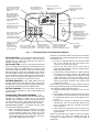
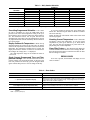
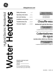
TOTALINE 1c.eps
OWNER’S
MANUAL
gold1.pdf
Residential
Programmable
Thermostat
Part Numbers P274-1100, 1200, 1300
As an ENERGY STAR® Partner, Carrier Corporation
has determined that this product meets the
ENERGY STAR guidelines for energy efficiency.
.
IMPORTANT: Read entire instructions before programming the thermostat.
GENERAL
The Totaline® 7-day programmable thermostats are wallmounted, low-voltage thermostats which maintain room temperature by controlling the operation of an HVAC (heating,
ventilation and air conditioning) system. Separate heating and
cooling settings and auto-changeover capability allow setback
of programming schedules for energy savings.
All thermostats allow up to 4 time/temperature settings to
be programmed per 24-hour period. Each thermostat stores
programs for 7 independent days. Batteries are not required.
During power interruption the internal memory stores programs for an unlimited time and the clock continues to run for
at least 72 hours.
The Energy Star logo indicates this thermostat is designed
to significantly improve heating and cooling comfort levels
while reducing the cost to heat and cool indoor air space.
THERMOSTAT OPERATION
Thermostat Display — The thermostat display is located in the top center of the thermostat. See Fig. 1. The following
information can be displayed on the screen:
• mode (OFF, HEAT, COOL, AUTO, or EHEAT [P2741200,1300 models only])
• fan setting (ON or AUTO)
• hold status
• auxiliary heat status (AUX HT [P274-1200,1300 models
only])
• room temperature
• desired temperature
• clean filter status
• time of day
• day of the week
Programming the Thermostat — The thermostat has
programming buttons which allow time and temperature to be
entered into the thermostat. The programming buttons are behind the thermostat cover. To access the programming buttons,
pull on the hinged thermostat cover. See Fig. 1. The programming buttons are: Copy Previous Day, Program, Mode, Change
Day, End Program, Fan, Set Time, Reset Filter, and Hold.
The Up and Down buttons are used to change the current,
desired temperature set point and to scroll through programming settings. The Up and Down buttons are accessible from
the outside of the thermostat.
Manufacturer reserves the right to
discontinue, or change at any time,
specifications or designs without notice
and without incurring obligations.
The daily schedule can be overridden in 2 ways: pressing
the Hold button or pressing the Up and Down buttons to
change the temperature set point.
HOLD BUTTON — Pressing the Hold button disables the
time and temperature schedule and holds the current desired
temperature set point. When a Hold is active, the HOLD
annunciator is displayed on the thermostat screen. The Hold
will remain active indefinitely. While HOLD mode is active
the set points can be adjusted and will remain at last changed
set point in HOLD mode for as long as HOLD mode remains
active. To release the Hold, press the Hold button a second
time.
FAN BUTTON — The Fan button selects fan operation.
When the fan is set to ON, the fan will run continuously for
improved air circulation. When the fan is set to AUTO, the fan
will run during heating and cooling operation only.
MODE BUTTON — The Mode button selects the operating
mode of the thermostat. If OFF is selected, the thermostat will
not enter Heating or Cooling mode. If HEAT is selected, the
thermostat will only enter Heating mode (if the room temperature is below the heating set point). If COOL is selected, the
thermostat will only enter Cooling mode (if the room temperature is above the cooling set point). If AUTO is selected, the
thermostat will enter Heating or Cooling mode based on the
room temperature and the heating and cooling settings. Heat
pump thermostats also have an EHEAT selection. If EHEAT is
configured by installer, the unit will use the second stage of
heating to provide heating if necessary. The annunciator for
each selection will be displayed on the thermostat when
selected.
AUTO-CHANGEOVER — When the thermostat mode is set
to AUTO, the thermostat will provide automatic changeover
from Heating to Cooling mode and Cooling to Heating mode
when required. The thermostat will automatically switch to
maintain the desired temperature setting. The thermostat does
not need to be manually changed from heating to cooling or
cooling to heating operation.
NOTE: It is recommended that auto-changeover mode not be
used if the outdoor temperature is consistently lower than 50 F
or greater than 80 F. In these cases, select Heating or Cooling
mode only.
SMART RECOVERY (HEATING MODE) — The smart
recovery function is designed to save energy by gradually
adjusting temperatures to meet scheduled set points. The Smart
Recovery function begins 1 to 1.5 hours before a scheduled set
point increase and gradually adjusts room temperature so the
temperature is at the new set point when the time period
begins. This is more efficient than making the system run at
full capacity until the desired temperature is met.
NOTE: Smart recovery does not apply to cooling operation.
REPLACEMENT COMPONENTS DIVISION
© CARRIER CORPORATION 1106 6-01
PRINTED IN U.S.A.
LITERATURE NUMBER P274-4SO
REPLACES: New
CATALOG NUMBER 570-203
*Auxiliary Heat Indicator
lights up when a heat
pump system’s auxiliary
heat is on.
Room Temperature
Display shows current
room temperature.
Mode Button selects
OFF, HEAT, COOL or
AUTO operation. Heat
pump thermostats
include EMERGENCY
HEAT mode.
Programmable
Thermostat
Fan
ON
AUTO
Program Button starts
programming process
and moves you from
one step to the next.
PROGRAM
MODE
CHANGE DAY
END PROGRAM
FAN
SET TIME
RESET FILTER
HOLD
COPY PREVIOUS DAY
Copy Previous Day
Button “memorizes” the
current day’s comfort
schedule and copies it into
the next day’s schedule.
Change Day Button
advances you to the
next day to be
programmed and
advances the day of
the week display.
Mode
HOLD
OFF
EHEAT
COOL
AUTO
Outdoor Temperature
Display shows the outdoor
temperature.
Desired Temperature
Display shows desired
temperature for current
time period.
WAKE DAY EVE SLEEP
Mo Tu We Th Fr
Sa Su
TIME AM PM
COOL
Time of Day Display
HEAT
CLEAN FILTER
AUX HT
PROGRAMMING
Clean Filter Indicator
lets you know it is time to
clean or replace your
system’s air filter.
Up and Down Buttons
change the desired
temperature setting, turn on
the LCD backlight, are used
for programming and, on
selected models, access
outdoor temperature.
Set Time
Buttom
End Program Button “locks
in” the most recently entered
temperatures and schedule.
Reset Filter Button
restarts the timer that
determines the next air
filter change or cleaning.
Hold Button maintains the
current temperature and
overrides programmed
temperature changes until reset.
Fan Button
chooses ON or
AUTO fan
operation.
Fig. 1 — Thermostat Display and Programming Buttons
NOTE: If a programming button is not pushed for 2 minutes,
the thermostat will exit Programming mode and any changes
made will be saved.
2. Press the Up and Down buttons to set the desired start
time for the schedule day and period shown. Time
selection is in 15-minute increments.
3. Press the Set Time button once the correct time is
shown. The TIME indicator will stop flashing and the
HEAT indicator will flash.
4. Using the daily comfort schedule as a guide, program
the heating and cooling settings. The HEAT and
COOL indicators will flash for the heating and cooling
settings respectively. The Set Time button is used to
toggle between the time, heating, and cooling settings.
Use the Up and Down buttons to raise and lower the
temperature set points.
NOTE: There must be at least 2 degrees difference between
the cooling and heating settings. The thermostat will automatically change any settings closer than 2 degrees.
5. Press the Program button to advance to the next time
period.
6. Perform Steps 2 through 5 until the times and temperature settings have been entered for the entire day. Press
the Change Day button to move to the schedule for the
next day.
7. Repeat Steps 2 through 6 to program the remaining
schedule days. The Copy Previous Day button can be
used to copy the previous day’s schedule if the schedules are the same.
8. After all the times and settings for each day have been
entered, press the End Program button to finish entering the schedule.
NOTE: The thermostat will continue to follow the schedule
until a new one is entered. The schedule may need to
be updated for different seasons or prolonged changes in
temperature.
Set Current Day — The Change Day button will change
the day shown on the thermostat display to the next day. If a
schedule has been entered, the thermostat will follow the
schedule of the new selected day.
Set Current Time — The Set Time/Temp button allows
the user to change the time displayed on the thermostat. Press
the Set Time button. The TIME indicator will flash. Press the
Up and Down buttons until the correct time is shown. Hold
down the buttons to quickly move through the time display.
The AM and PM indicators will automatically change. To ensure the schedules are properly followed, make sure that AM or
PM is correct for the time chosen. When the correct time is
shown, press the End button to exit the Set Time mode.
Set Mode Operation — The Mode button selects the
operation of the system (OFF, HEAT, COOL, AUTO). Press
the Mode button to select the desired setting. Heat pump thermostats also include Emergency Heat (EHEAT) mode.
Set Fan Operation — The Fan button will allow the
system fan to run continuously or only as desired during heating and cooling.
Programming Thermostat Schedules — Before programming the thermostat, plan the thermostat daily
schedule. The schedule is divided into 4 time periods
(WAKE, DAY, EVENING, SLEEP). Each time period has a
start time, heating set point, and cooling set point. Fill in Table 1 below as an aid to programming the daily schedules.
PROGRAMMING MODE — To program the daily schedules, perform the following procedure:
1. Enter Programming mode by pressing the Program
button. The PROGRAMMING indicator will appear
on the thermostat display. The current day of the
schedule will be displayed above the clock and the current programming time period of that day will be displayed. The TIME indicator will flash.
2
Table 1 — Daily Comfort Schedule
DAY OF
THE WEEK
SCHEDULE
DAY
EVENING
Time / Heat / Cool
Time / Heat / Cool
WAKE
Time / Heat / Cool
SLEEP
Time / Heat / Cool
Monday
/
/
/
/
/
/
/
/
Tuesday
/
/
/
/
/
/
/
/
Wednesday
/
/
/
/
/
/
/
/
Thursday
/
/
/
/
/
/
/
/
Friday
/
/
/
/
/
/
/
/
Saturday
/
/
/
/
/
/
/
/
Sunday
/
/
/
/
/
/
/
/
NOTE: The cooling temperature set point must be at least 2 degrees higher than the heating temperature set point.
Overriding Programmed Schedule — The sched-
To view the program for the next day, press Change Day
button once. Press the Program button to advance to another
time on the same day.
NOTE: Pressing any other buttons while in this mode could
alter the set program.
ule can be overridden in 2 ways: the Hold button can be
pressed to lock in the current temperature setting or the Up or
Down buttons can be pressed to change the desired temperature. The thermostat will use new set point until the next
scheduled time period starts. Once the Hold button is pressed,
any adjustments made will last indefinitely until the Hold button is pressed again.
Checking Current Temperature — The thermostat
will display current room temperature. To view the current
temperature set points, press either the Up or Down button
once. The heat and cool temperature set points will be displayed along side of room temperature.
Display Outdoor-Air Temperature — When the Up
and Down buttons are pressed at the same time, the display
will show the temperature of the outdoor sensor (if wired to the
thermostat). The temperature is displayed for 4 seconds. The
display then returns to normal. If a sensor is not connected or
the reading is out of range, then “--” is displayed.
The valid temperature range for the outdoor-air sensor is
–38 to 145 F.
Clean Filter Feature — The thermostat will display the
CLEAN FILTER indicator when it is time to change the filter.
Press the Reset Filter button to restart the timer after the filter
has been changed or cleaned.
ERROR CODES
Check Current Programmed Time and Temperature Settings — To check the current time and tem-
If an error is present, the thermostat will display an error
code. See Table 2.
perature settings, press the Program button. To advance to the
next time period on the same day, press the Program button
again. Continue this process to view all settings for the day.
Table 2 — Error Codes
CODE
Blank LCD
“--” (2 dashes) on temperature display
“E2” displayed on thermostat
“E3” flashing on thermostat and alternating with
room temperature (heat pump thermostats)
“E4” displayed on thermostat
DESCRIPTION
No power to thermostat. Contact dealer for further information.
Temperature sensor (inside thermostat) reading is out of range. Check sensor for
damage. The outdoor temperature sensor (if installed) is open, not connected, or
shorted (both buttons pushed simultaneously). If recycling power does not clear
display, thermostat should be replaced.
Not enough voltage for the thermostat. Contact dealer for further information.
The outdoor thermostat is in error, not connected, or shorted out. This code is
displayed only if auxiliary heat and/or cool lockout feature is enabled.
Problem with the thermostat memory.
LEGEND
LCD — Liquid Crystal Display
3
→
Replacement Components Division
Carrier Corporation
RESIDENTIAL THERMOSTAT
LIMITED FIVE-YEAR WARRANTY
TOTALINE 1c.eps
FIVE-YEAR WARRANTY — This CARRIER CORPORATION product is warranted to be free from defects in
material and workmanship under normal use and maintenance for a period of five years from the date of original
installation. A new or remanufactured part to replace the defective part will be provided without charge for the
part itself, through a qualified servicing CARRIER CORPORATION dealer or service, PROVIDED the defective
part is returned to our distributor. The replacement part assumes the unused portion of the warranty.
THIS WARRANTY DOES NOT INCLUDE ANY ADDITIONAL LABOR ALLOWANCE OR OTHER COSTS
incurred for diagnosis, repairing, removing, installing, shipping, servicing, or handling of either defective parts or
replacement parts. SUCH COSTS MAY BE COVERED BY a separate warranty provided by the installer.
LIMITATIONS OF WARRANTIES — ALL IMPLIED WARRANTIES (INCLUDING IMPLIED WARRANTIES OF
MERCHANTABILITY) ARE HEREBY LIMITED IN DURATION TO THE PERIOD FOR WHICH THE LIMITED
WARRANTY IS GIVEN. THE EXPRESSED WARRANTIES MADE IN THIS WARRANTY ARE EXCLUSIVE
AND MAY NOT BE ALTERED, ENLARGED, OR CHANGED BY ANY DISTRIBUTOR, DEALER, OR OTHER
PERSON WHATSOEVER.
CARRIER WILL NOT BE RESPONSIBLE FOR:
1. Normal maintenance as outlined in the installation and servicing instructions or owner’s manual.
2. Damage or repairs required as a consequence of faulty installation or application by others.
3. Failure to start due to voltage conditions, blown fuses, open circuit breakers or other damages due to the
inadequacy or interruption of electrical service.
4. Damage or repairs needed as a consequence of any misapplication, abuse, improper servicing, unauthorized alteration, or improper operations.
5. Damage as a result of floods, winds, fires, lightning, accidents, corrosive atmosphere, or other conditions
beyond the control of CARRIER CORPORATION.
6. Parts not supplied or designated by CARRIER CORPORATION.
7. CARRIER CORPORATION products installed outside the continental U.S.A., Alaska, Hawaii, and Canada.
8. Electricity or fuel costs or increases in electricity or fuel costs from any reason whatsoever including additional or unusual use of supplemental heat.
9. ANY SPECIAL INDIRECT OR CONSEQUENTIAL PROPERTY OR COMMERCIAL DAMAGE OF ANY
NATURE WHATSOEVER. Some states do not allow the exclusion of incidental or consequential damages,
so the above limitation may not apply to you.
Model No.
Unit Serial No.
Date of Installation
Installed by
Name of Owner
Address of Installation
Manufacturer reserves the right to
discontinue, or change at any time,
specifications or designs without notice
and without incurring obligations.
REPLACEMENT COMPONENTS DIVISION
© CARRIER CORPORATION 1106 6-01
PRINTED IN U.S.A.
LITERATURE NUMBER P274-4SO
REPLACES: New
CATALOG NO. 570-203