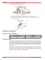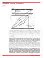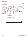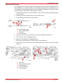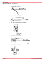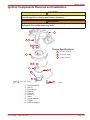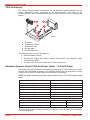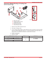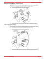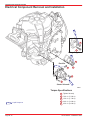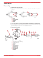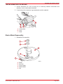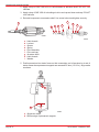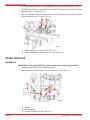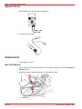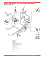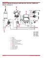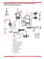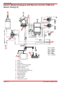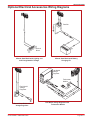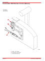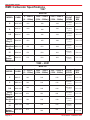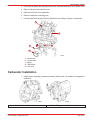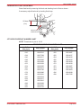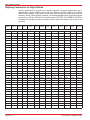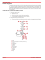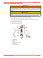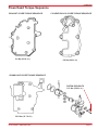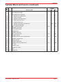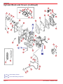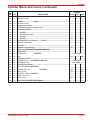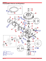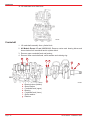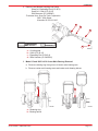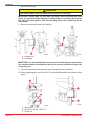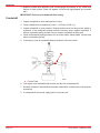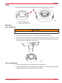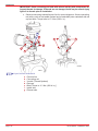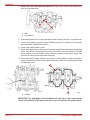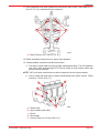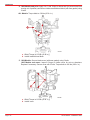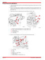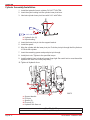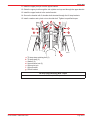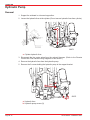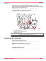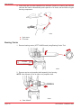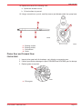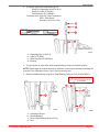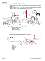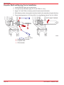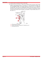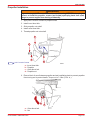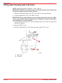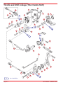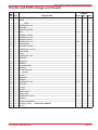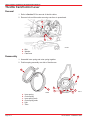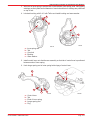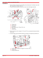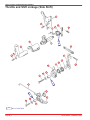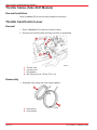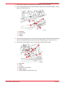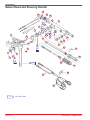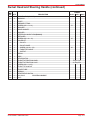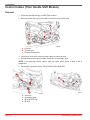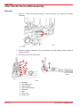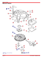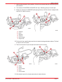
1
Service Manual Outline
Section 1 - General Information & Specifications
A - Specifications
B - Maintenance
C - General Information
D - Outboard Installation
Section 2 - Electrical and Ignition
A - Ignition System
B - Charging & Starting System
C - Timing/Synchronizing & Adjusting
D - Wiring Diagrams
Section 3 - Fuel System
A - Fuel Delivery System
B - Emissions
Section 4 - Powerhead
Section 5 - Mid-Section
A - Clamp/Swivel Brackets and Driveshaft Housing
B - Power Trim
Section 6 - Lower Unit
Section 7 - Attachments/Control Linkage
A - Throttle/Shift Linkage (Tiller Handle Shift Models)
B - Throttle/Shift Linkage (Side Shift Models)
C - Tiller Handle
Section 8 - Manual Starter
90-827242R02 FEBRUARY 2003
General Information
& Specifications
1
Electrical and Ignition
2
Fuel System
3
Powerhead
4
Mid-Section
5
Lower Unit
6
Attachments/
Control Linkage
7
Manual Starter
8
Page iii
Notice
Throughout this publication, Dangers, Warnings and Cautions (accompanied by the
International HAZARD Symbol
) are used to alert the mechanic to special instructions
concerning a particular service or operation that may be hazardous if performed incorrectly
or carelessly. OBSERVE THEM CAREFULLY!
These Safety Alerts alone cannot eliminate the hazards that they signal. Strict compliance
to these special instructions when performing the service, plus Common Sense operation,
are major accident prevention measures.
DANGER
DANGER - Immediate hazards which WILL result in severe personal injury or death.
WARNING
WARNING - Hazards or unsafe practices which COULD result in severe personal
injury or death.
CAUTION
Hazards or unsafe practices which could result in minor personal injury or product
or property damage.
Notice to Users of This Manual
This service manual has been written and published by the Service Department of Mercury
Marine to aid our dealers’ mechanics and company service personnel when servicing the
products described herein.
It is assumed that these personnel are familiar with the servicing procedures of these
products, or like or similar products manufactured and marketed by Mercury Marine, that
they have been trained in the recommended servicing procedures of these products which
includes the use of mechanics’ common hand tools and the special Mercury Marine or
recommended tools from other suppliers.
We could not possibly know of and advise the service trade of all conceivable procedures
by which a service might be performed and of the possible hazards and/or results of each
method. We have not undertaken any such wide evaluation. Therefore, anyone who uses
a service procedure and/or tool, which is not recommended by the manufacturer, first must
completely satisfy himself that neither his nor the products safety will be endangered by the
service procedure selected.
All information, illustrations and specifications contained in this manual are based on the
latest product information available at the time of publication. As required, revisions to this
manual will be sent to all dealers contracted by us to sell and/or service these products.
It should be kept in mind, while working on the product, that the electrical system and ignition
system are capable of violent and damaging short circuits or severe electrical shocks. When
performing any work where electrical terminals could possibly be grounded or touched by
the mechanic, the battery cables should be disconnected at the battery.
Any time the intake or exhaust openings are exposed during service they should be covered
to protect against accidental entrance of foreign material which could enter the cylinders and
cause extensive internal damage when the engine is started.
90-827242R02 FEBRUARY 2003
Page i
It is important to note, during any maintenance procedure replacement fasteners must have
the same measurements and strength as those removed. Numbers on the heads of the
metric bolts and on the surfaces of metric nuts indicate their strength. American bolts use
radial lines for this purpose, while most American nuts do not have strength markings.
Mismatched or incorrect fasteners can result in damage or malfunction, or possibly personal
injury. Therefore, fasteners removed should be saved for reuse in the same locations
whenever possible. Where the fasteners are not satisfactory for re-use, care should be
taken to select a replacement that matches the original.
Cleanliness and Care of Outboard Motor
A marine power product is a combination of many machined, honed, polished and lapped
surfaces with tolerances that are measured in the ten thousands of an inch/mm. When any
product component is serviced, care and cleanliness are important. Throughout this
manual, it should be understood that proper cleaning, and protection of machined surfaces
and friction areas is a part of the repair procedure. This is considered standard shop practice
even if not specifically stated.
Whenever components are removed for service, they should be retained in order. At the
time of installation, they should be installed in the same locations and with the same mating
surfaces as when removed.
Personnel should not work on or under an outboard which is suspended. Outboards should
be attached to work stands, or lowered to ground as soon as possible.
We reserve the right to make changes to this manual without prior notification.
Refer to dealer service bulletins for other pertinent information concerning the products
described in this manual.
Page ii
90-827242R02 FEBRUARY 2003
Propeller Information
For in-depth information on marine propellers and boat performance – written by marine
engineers – see your Authorized Dealer for the illustrated “What You Should Know About
Quicksilver Propellers... and Boat Performance Information” (Part No. 90-86144 92).
How To Use This Manual
The manual is divided into SECTIONS which represents major components and systems.
Some SECTIONS are further divided into PARTS. Each PART has a title page. A Table of
Contents for the particular PART is printed on the back of the title page.
SECTIONS and PARTS are listed on the Service Manual Outline sheet which immediately
follows the cover of this book.
Page Numbering
Two number groups appear at the bottom of each page. The example, below, is
self-explanatory.
EXAMPLE:
90-827242R1 MAY 1998
Revision No. 1
Month of Printing
Year of Printing
Page iv
Page 2B-7
Section Number
Part of Section Letter
Page Number
90-827242R02 FEBRUARY 2003
SPECIFICATIONS
GENERAL INFORMATION & SPECIFICATIONS
1
Section 1A – Specifications
A
Table of Contents
General Specifications . . . . . . . . . . . . . . . . . . .
Propeller Information Chart - 6 HP . . . . . . . . .
Propeller Information Chart - 8 HP . . . . . . . . .
1A-1
1A-6
1A-6
Propeller Information Chart -9.9/10 HP . . . . .
Propeller Information Chart -15 HP . . . . . . . .
Mercury/Quicksilver Lubricants and Sealants
1A-7
1A-7
1A-8
General Specifications
Models 6/8/9.9/10/15
PERFORMANCE
KW
(HP)
OUTBOARD
WEIGHT
Model 6
Model 8
Model 8 Sailmate
Model 9.9
Model 9.9 Sailpower
XR/MAG/Viking10
Model Sea Pro/Marathon 10
Model 15
Model Sea Pro/Marathon 15
Manual Start
6
8
8 Sailmate
9.9
9.9 Sailpower
XR/MAG/Viking10
Sea Pro/Marathon 10
15
Sea Pro/Marathon 15
Electric Start
6
8
9.9
9.9 Sailpower
15
Recommended Gasoline
Recommended Oil
Ratio
FUEL SYSTEM
Fuel Tank Capacity
6/8/9.9/Sailpower, XR/MAG10
10 Sea Pro
Marathon/15
90-827242R02 FEBRUARY 2003
4.5 (6)
5.9 (8)
5.9 (8)
7.4 (9.9)
7.4 (9.9)
7.5 (10)
7.5 (10)
11.2 (15)
11.2 (15)
33.1 kg (73.0 lb)
33.1 kg (73.0 lb)
33.8 kg (74.5 lb)
33.8 kg (74.5 lb)
34.2 kg (76.5 lb)
33.8 kg (74.5 lb)
33.8 kg (74.5 lb)
34.0 kg (75.0 lb)
34.0 kg (75.0 lb)
36.1 kg (79.5 lb)
36.1 kg (79.5 lb)
36.7 kg (81.0 lb)
37.7 kg (83.0 lb)
37.0 kg (81.5 lb)
Automotive Unleaded
with a Minimum Pump Posted
Octane Rating of 86
2 Cycle Outboard Oil
25:1 (During break-in)
50:1 (After break-in)
12.0 L, 2.7 Imp Gal., 3.2 U.S. Gal.
25.0 L, 5.5 Imp Gal., 6.6 U.S. Gal.
Page 1A-1
SPECIFICATIONS
CYLINDER
BLOCK
CYLINDER
BORE
STROKE
Type
Displacement (1994 Model)
6
8
9.9
9.9 Sailpower
10 Sea Pro/Marathon
XR10/MAG10
15
Displacement (1995 and Newer)
9.9
9.9 Sailpower
10 Sea Pro/Marathon
XR/MAG/Viking 10
15
15 Sea Pro/Marathon
Diameter (Standard)(1994 Model)
6
8
8 Sailmate
9.9
9.9 Sailpower
10 Sea Pro/Marathon
XR/Mag 10
15
Diameter (Standard)(1995 Model)
9.9
9.9 Sailpower
10 Sea Pro/Marathon
XR/Mag/Viking 10
15
15 Sea Pro/Marathon
Taper/Out of Round Maximum
Bore Type
Two-Stoke Cycle – Cross Flow
209 cc (12.8 cu. in.)
209 cc (12.8 cu. in.)
209 cc (12.8 cu. in.)
209 cc (12.8 cu. in.)
262 cc (16.0 cu. in.)
262 cc (16.0 cu. in.)
262 cc (16.0 cu. in.)
262 cc (16.0 cu. in.)
262 cc (16.0 cu. in.)
262 cc (16.0 cu. in.
262 cc (16.0 cu. in.)
262 cc (16.0 cu. in.)
262 cc (16.0 cu. in.)
53.975 mm (2.125 in.)
53.975 mm (2.125 in.)
53.975 mm (2.125 in.)
53.975 mm (2.125 in.)
53.975 mm (2.125 in.)
60.325 mm (2.375 in.)
60.325 mm (2.375 in.)
60.325 mm (2.375 in.)
60.325 mm (2.375 in.)
60.325 mm (2.375 in.)
60.325 mm (2.375 in.)
60.325 mm (2.375 in.)
60.325 mm (2.375 in.)
60.325 mm (2.375 in.)
0.1016 mm (0.004 in.)
Cast Iron
Length
45.7 mm (1.800 in.)
CRANKSHAFT
Top Main Bearing Journal
Center Main Bearing Journal
Bottom Ball Bearing Journal
Connecting Rod Journal
Runout
19.1 mm (0.7517 in.)
20.6 mm (0.8108 in.)
20.0 mm (0.7880 in.)
20.6 mm (0.8125 in.)
0.076 mm (0.003 in.)
CONNECTING
ROD
Piston Pin End (I.D.)
Crankpin End (I.D.)
20.8 mm (0.8195 in.)
27.0 mm (1.0635 in.)
Piston Type
Ring End Gap
Aluminum
0.25 mm - 0.46 mm
(0.010 in. - 0.018 in.)
PISTON
REEDS
Page 1A-2
Reed Stand Open (Maximum)
All Models
Reed Stop Opening (Maximum)
All Models
0.178 mm (0.007 in.)
7.54 mm (0.296 in.)
90-827242R02 FEBRUARY 2003
SPECIFICATIONS
GEAR
HOUSING
Gear Ratio
Gearcase Capacity
Lubricant Type
Forward Gear - Tooth count - Type
Pinion Gear - Tooth count - Type
Pinion Height
Forward Gear Backlash
Reverse Gear Backlash
Water Pressure
With Thermostat
– @ W.O.T (5000 RPM)
– @ Idle (750 RPM)
W/O Thermostat
– @ W.O.T (5000 RPM)
– @ Idle (750 RPM)
Transom Height
MID
SECTION
Short Shaft
Long Shaft
Extra Long Shaft
Steering Pivot Range
Tilt Pin Positions
Total Tilt Angle
Allowable Transom Thickness
Fuel
Recommended Gasoline
Recommended Oil
FUEL
SYSTEM
Gasoline/Oil Ratio
Fuel Tank Capacity
6/8/9.9/9.9 Sailpower
XR/MAG/10 Sea Pro/
Marathon/15
STARTING
SYSTEM
CHARGING
SYSTEM
Manual Start
Electric Start
Starter Draw (Under Load)
(No Load)
Alternator Output
BLACK Stator - 2 Magnet Flywheel
(8 Pole)(4 Pulses)
RED Stator - 4 Magnet Flywheel
(10 Pole)(5 Pulses)
90-827242R02 FEBRUARY 2003
2.0:1
200 ml (6.8 fl. oz.)
Quicksilver Gear Lube Premium Blend
26 Spiral/Bevel
13 Spiral/Bevel
Floating
No Adjustment
No Adjustment
34.5 - 48.3 kPa (5 - 7 PSI)
3.4 - 10.3 kPa (.5 – 1.5 PSI)
34.5 - 48.3 kPa (5 – 7 PSI)
0 - 7 kPa (0 – 1 PSI)
38 cm (15 in.)
51 cm (20 in.)
63.5 cm (25 in.)
78°
3 + 3 Shallow Water
78°
60.3 mm (2-3/8 in.)
Pre-Mixed Gasoline and Oil
Automotive Lead-Free
2 Cycle Outboard Oil
25:1 (During Break-In)
50:1 (After Break-In)
12.0 L, 3.2 U.S. Gal.
25.0 L, 6.6 U.S. Gal.
Recoil
12 Volt
55 Amperes
15 Amperes
4 Amp. (48 Watt)
@ 6000 RPM
6 amp (72 Watt)
@ 6000 RPM
Page 1A-3
SPECIFICATIONS
BATTERY
Battery Rating
Type
SPARK PLUG (1994)
6/8/9.9
10/15
SPARK PLUG GAP (1994)
6/8/9.9
10/15
SPARK PLUG (1995 AND NEWER)
6/8
9.9/10/15
IGNITION
SYSTEM
SPARK PLUG GAP (1995 AND
NEWER)
6/8
9.9/10/15
Firing Order
Stator High Speed Winding
Stator Low Speed Winding
Diode Test
Ignition Coil Resistance:
Primary
Secondary
Trigger
465 Marine Cranking Amps (MCA)
or 350 Cold Cranking Amps (CCA)
Capacitor Discharge
NGK BP8H-N-10
NGK BP8HS-15
NGK BPZ8H-N-10*
1.0 mm (0.040 in.)
1.5 mm (0.060 in.)
NGK BP8H-N-10
NGK BP8HS-15
NGK BPZ8H-N-10*
1.0 mm (0.040 in.)
1.5 mm (0.060 in.)
1-2
120 - 180 Ω (BLACK/WHITE GROUND)
3200 - 3800 Ω (BLACK/YELLOW GROUND)
3100 – 3700 Ω (BLACK/YELLOW BLACK/WHITE)
0.02 - 0.04 Ω
8000 - 11000 Ω
6500 - 8500 Ω
NOTE: *Use NGK-BPZ8H-N-10 where radio frequency interference (RFI) suppression is
required.
Page 1A-4
90-827242R02 FEBRUARY 2003
SPECIFICATIONS
Type
Idle RPM (In Gear)
6
8
9.9/9.9 Sailpower
10 Sea Pro/Marathon
XR/MAG/Viking 10
15
Wide Open Throttle RPM
6
8
9.9/9.9 Sailpower
10 Sea Pro/Marathon
XR/MAG/Viking 10
15
15 Sea Pro/Marathon
Idle Mixture Screw (Initial Setting)
CARBURETOR
Float Setting (All Models)
SPECIFICATIONS
Main Jet –
Thread size
6
8
9.9/9.9 Sailpower
10 Sea Pro/Marathon
XR/MAG 10
15
6
8
9.9/9.9 Sailpower
10 Sea Pro/Marathon
XR/MAG 10
15/Viking 10
15 Sea Pro/Marathon
Idle
6
8/8 Sailmate
9.9/9.9 Sailpower
10 Sea Pro/Marathon
TIMING
XR/MAG/Viking 10
SPECIFICATIONS
15
15 Sea Pro/Marathon
Maximum BTDC @ 4500 RPM – All
Models
90-827242R02 FEBRUARY 2003
Center Bowl, Integral Fuel Pump
650 ± 75
725 ± 50
725 ± 50
850 ± 50
725 ± 50
725 ± 50
4000 – 5000
4500 – 5500
5000 – 6000
5000 – 6000
5000 – 6000
5000 – 6000
5000 – 6000
Refer to Section 3 for Specifics
25.4 mm (1 in.)
10–32
1994 Model Year
.042
.046
.052
.064
.052
.066
1995 and Newer
.042
.046
.048
.052
.052
.072
.072
8° BTDC ± 1°
8° BTDC ± 1°
8° BTDC ± 1°
8° BTDC ± 1°
8° BTDC ± 1°
8° BTDC ± 1°
8° BTDC ± 1°
36° BTDC
Page 1A-5
SPECIFICATIONS
Propeller Information Chart - 6 HP
Wide Open Throttle RPM: 4000-5000
Recommended Transom Height: 15″, 20″, 25″
Right Hand Rotation Standard
Gear Reduction: 2:1
Diameter
Pitch
No. Of
Blades
Material
Typical Gross
Boat WGT.
(LBS)
Typical Boat
Length
Speed
Range
(MPH)
Propeller Part
Number
9″
9″
3
Alum.
Up To 1400
Up To 15′
10-19
48-828156A12
9″
8″
3
Alum.
1000 – 2200
12′ - 16′
8-15
48-828154A12
9-1/4″
7″
3
Alum.
1200 – 2600
13′ - 17′
5-12
48-828152A12
9-3/4″
6-1/2″
3
Alum.
1500+
High Reverse
Thrust
3-10
48-828150A12
9-3/4″
5-1/2″
3
Alum.
1900+
Workboat
1-8
48-828148A12
Thrust Hub:
42630 1 (Forward)
Propeller Drive Hub:
827598T
Diffuser Ring:
42594 (Aluminum)
Propeller Information Chart - 8 HP
Wide Open Throttle RPM: 4500-5500
Recommended Transom Height: 15″, 20″, 25″
Right Hand Rotation Standard
Gear Reduction: 2:1
Diameter
Pitch
No. Of
Blades
Material
Typical Gross
Boat WGT.
(LBS)
Typical Boat
Length
Speed
Range
(MPH)
Propeller Part
Number
9″
9″
3
Alum.
Up To 1200
Up To 16′
12-22
48-82815612
9″
8″
3
Alum.
1100 – 2000
14′ - 17′
10-20
48-828154A12
9-1/4″
7″
3
Alum.
900 – 2400
14′ - 18′
7-15
48-828152A12
9-3/4″
6-1/2″
3
Alum.
1400+
High Reverse
Thrust
4-12
48-828150A12
9-3/4″
5-1/2″
3
Alum.
1700+
Workboat
1-10
48-828148A12
Thrust Hub:
42630 1 (Forward)
Propeller Drive Hub:
827598T
Diffuser Ring:
42594 (Aluminum)
Page 1A-6
90-827242R02 FEBRUARY 2003
SPECIFICATIONS
Propeller Information Chart -9.9/10 HP
Wide Open Throttle RPM: 5000-6000
Recommended Transom Height: 15″, 20″, 25″
Right Hand Rotation Standard
Gear Reduction: 2:1
Diameter
Pitch
No. Of
Blades
Material
Typical Gross
Boat WGT.
(LBS)
Typical Boat
Length
Speed
Range
(MPH)
Propeller Part
Number
9″
9″
3
Alum.
Up To 1200
Up To 16′
12-24
48-828156A12
9″
8″
3
Alum.
1100 – 2000
14′ - 17′
12-22
48-828154A12
9-1/4″
7″
3
Alum.
900 – 2400
14′ - 18′
8-18
48-828152A12
9-3/4″
6-1/2″
3
Alum.
1400+
High Reverse
Thrust
5-15
48-828150A12
9-3/4″
5-1/2″
3
Alum.
1700+
Workboat
1-13
48-828148A12
Thrust Hub:
42630 1 (Forward)
Propeller Drive Hub:
827598T
Diffuser Ring:
42594 (Aluminum)
Propeller Information Chart -15 HP
Wide Open Throttle RPM: 5000-6000
Recommended Transom Height: 15″, 20″, 25″
Right Hand Rotation Standard
Gear Reduction: 2:1
Diameter
Pitch
No. Of
Blades
Material
Typical Gross
Boat WGT.
(LBS)
Typical Boat
Length
Speed
Range
(MPH)
Propeller Part
Number
9″
10-1/2″
3
Alum.
Up To 1000
Up To 16′
18-28
48-828158A12
9″
9″
3
Alum.
600 – 1500
14′ - 18′
14-24
48-828156A12
9″
8″
3
Alum.
800 – 2400
15′ - 20′
15-25
48-828154A12
9-1/4″
7″
3
Alum.
1000 – 3400
16′ - 22′
8-18
48-828152A12
9-3/4″
6-1/2″
3
Alum.
1800+
High Reverse
Thrust
1-15
48-828150A12
Thrust Hub:
42630 1 (Forward)
Propeller Drive Hub:
827598T
Diffuser Ring:
42594 (Aluminum)
90-827242R02 FEBRUARY 2003
Page 1A-7
SPECIFICATIONS
Mercury/Quicksilver Lubricants and Sealants
Tube
Ref. No.
Description
Mercury Part Number
Quicksilver Part
Number
4
Needle Bearing Assembly Lubricant
92-802868A1
N/A
92-823506-1
92-823506-1
6
7
Loctite 271 – Thread
Locker
92-809819
92-809819
9
Loctite 567 PST Pipe
Sealant
92-809822
92-809822
12
Loctite Master Gasket
Kit
92-12564-2
92-12564-2
14
2 Cycle Premium Outboard Oil
92-802813A1
92-802813Q1
19
Perfect Seal
92-34227-1
92-34227-1
Liquid Neoprene
92-25711-3
92-25711-3
Bellows Adhesive
N/A
92-86166Q1
33
Loctite 680 Retaining
Compound
92-809833
92-809833
34
Special Lubricant 101
92-802865A1
92-802865Q1
U-Joint and Gimbal
Bearing Grease
92-802870A1
92-802870Q1
25
27
42
51
Loctite 222 Thread
Locker
92-809818
92-809818
66
Loctite 242 Thread
Locker
92-809821
92-809821
79
4 Cycle 25W40 Engine
Oil
92-802837A1
92-802837Q1
82
Premium Gear Lubricant
92-802846A1
92-802846Q1
87
High Performance
Gear Lube
92-802854A1
92-802854Q1
91
Engine Coupler Spline
Grease
92-802869A1
92-802869Q1
94
Anti-Corrosion Grease
92-802867A1
92-802867Q1
95
2-4-C with Teflon
92-802859A1
92-802859Q1
4 Stroke 10W30 Outboard Oil
92-802833A1
92-802833Q1
Power Trim & Steering
Fluid
92-802880A1
92-802880Q1
110
114
Page 1A-8
Dielectric Grease
90-827242R02 FEBRUARY 2003
SPECIFICATIONS
Mercury Part Number
Quicksilver Part
Number
92-802824A1
92-802824Q1
RTV 587 Silicone
Sealer
92-809825
92-809825
117
Loctite 7649 Primer N
92-809824
92-809824
119
Storage Seal Rust Inhibitor
92-802878-56
92-802878Q56
120
Corrosion Guard
92-802878 55
92-802878Q55
121
15W40 4-cycle Diesel
Engine Oil
92-877695K1
92-877695Q1
122
Extended Life Antifreeze/Coolant
92-877770K1
92-877770K1
123
Marine Engine Coolant
NA
92-813054A2
124
Fuel System Treatment and Stabilizer
Concentrate
92-802876A1
92-802876Q1
125
Heat Transfer Compound
92-805701 1
126
Liquid Gasket
92-808137
NA
127
T442 Sealant
92-862258
NA
Loctite 5900 Ultra
Black RTV Silicone
Sealant
92-809826
NA
128
129
Loctite Gasket Remover
92-809828 1
NA
130
Sealer Kit, Two Part
Epoxy
NA
92-65150 1
131
Anti-seize Compound
92-881091K1
132
Torco MTF Gear Oil
92–849864–1
133
Optimol Longtime PD
2
92–848767
134
Dexron III Automatic
Transmission Fluid
Obtain Locally
Obtain Locally
135
Loctite 592
Obtain Locally
Obtain Locally
136
Loctite Quick Tite
Obtain Locally
Obtain Locally
137
Isopropyl Alcohol
Obtain Locally
Obtain Locally
138
Hot Glue
Obtain Locally
Obtain Locally
139
Loctite 609
Obtain Locally
Obtain Locally
1
140
Loctite 405
Obtain Locally
Obtain Locally
Tube
Ref. #
Description
115
Premium Plus 2 Cycle
TC-W3 Outboard Oil
116
90-827242R02 FEBRUARY 2003
Page 1A-9
SPECIFICATIONS
Page 1A-10
Tube
Ref. #
Description
Mercury Part Number
Quicksilver Part
Number
1
141
Cyanacrylate Adhesive
Obtain Locally
Obtain Locally
142
3M Permabond
#3M08155
Obtain Locally
Obtain Locally
143
Loctite 262
Obtain Locally
Obtain Locally
144
Loctite 290
Obtain Locally
Obtain Locally
145
Loctite 598 RTV Sealant
Obtain Locally
Obtain Locally
146
Insulating Compound
92–41669–1
90-827242R02 FEBRUARY 2003
MAINTENANCE
GENERAL INFORMATION & SPECIFICATIONS
1
Section 1B – Maintenance
B
Table of Contents
Table of Contents . . . . . . . . . . . . . . . . . . . . . . .
Gearcase Lubricant Capacity . . . . . . . . . . . . .
Special Tools . . . . . . . . . . . . . . . . . . . . . . . . . . .
Inspection and Maintenance Schedule . . . . .
Before Each Use . . . . . . . . . . . . . . . . . . . . .
After Each Use . . . . . . . . . . . . . . . . . . . . . . .
Every 100 Hours of Use or Once Yearly,
Whichever Occurs First . . . . . . . . . . . . . . .
Every 300 Hours of Use or Three Years .
Flushing The Cooling System . . . . . . . . . . . . .
Fuel System . . . . . . . . . . . . . . . . . . . . . . . . . . . .
Fuel Line Inspection . . . . . . . . . . . . . . . . . .
Engine Fuel Filter . . . . . . . . . . . . . . . . . . . .
Corrosion Control Anode . . . . . . . . . . . . . . . . .
Spark Plug Inspection . . . . . . . . . . . . . . . . . . . .
Battery Inspection . . . . . . . . . . . . . . . . . . . . . . .
90-827242R02 FEBRUARY 2003
1B-1
1B-2
1B-2
1B-3
1B-3
1B-3
1B-3
1B-3
1B-4
1B-5
1B-5
1B-5
1B-6
1B-6
1B-7
Fuse Replacement – Electric Start Remote
Control Models . . . . . . . . . . . . . . . . . . . . . . . . .
Lubrication Points . . . . . . . . . . . . . . . . . . . . . . .
Gearcase Lubrication . . . . . . . . . . . . . . . . . . . .
Gearcase Lubricant Capacity . . . . . . . . . .
Draining Gearcase . . . . . . . . . . . . . . . . . . .
Checking Lubricant Level and Refilling
Gearcase . . . . . . . . . . . . . . . . . . . . . . . . . . .
Storage Preparations . . . . . . . . . . . . . . . . . . . .
Fuel System . . . . . . . . . . . . . . . . . . . . . . . . .
Protecting External Engine Components
Protecting Internal Engine Components .
Gearcase . . . . . . . . . . . . . . . . . . . . . . . . . . .
Positioning Outboard for Storage . . . . . . .
Battery Storage . . . . . . . . . . . . . . . . . . . . . .
1B-7
1B-8
1B-10
1B-10
1B-10
1B-11
1B-12
1B-12
1B-12
1B-12
1B-12
1B-13
1B-13
Page 1B-1
MAINTENANCE
Gearcase Lubricant Capacity
Gear Case Ratio
Capacity
2.00:1
200.0 ml (6.8 fl. oz.)
Special Tools
1. Flushing attachment 12612Q2
2. Grease gun 91-37299Q2
Page 1B-2
90-827242R02 FEBRUARY 2003
MAINTENANCE
Inspection and Maintenance Schedule
Before Each Use
1. Check that lanyard stop switch stops the engine.
2. Visually inspect the fuel system for deterioration or leaks.
3. Check outboard for tightness on transom.
4. Check steering system for binding or loose components.
5. Visually check steering link rod fasteners for proper tightness.
6. Check propeller blades for damage.
After Each Use
1. Flush out the outboard cooling system if operating in salt or polluted water.
2. Wash off all salt deposits and flush out the exhaust outlet of the propeller and gearcase
with fresh water if operating in salt water.
Every 100 Hours of Use or Once Yearly, Whichever Occurs First
1. Lubricate all lubrication points. Lubricate more frequently when used in salt water.
2. Inspect and clean spark plugs.
3. Check fuel line filter for contaminants.
4. Check carburetor adjustments, if required.
5. Check corrosion control anodes. Check more frequently when used in salt water.
6. Drain and replace gearcase lubricant.
7. Lubricate splines on the drive shaft.∗
8. Electric start models – Inspect battery.
9. Remote control models – Check control cable adjustments. ∗
10. Remove engine deposits with Power Tune Engine Cleaner.
11. Check tightness of bolts, nuts, and other fasteners.
12. Clean fuel tank pick up filter.
Every 300 Hours of Use or Three Years
1. Replace water pump impeller (more often if overheating occurs or reduced water
pressure is noted).*
∗ These items should be serviced by an authorized dealer.
90-827242R02 FEBRUARY 2003
Page 1B-3
MAINTENANCE
Flushing The Cooling System
Flush the internal water passages of the outboard with fresh water after each use in salt,
polluted, or muddy water. This will help prevent a buildup of deposits from clogging the
internal water passages.
Use a Quicksilver accessory or equivalent flushing attachment.
WARNING
To avoid possible injury when flushing, remove the propeller. Refer to Propeller
Replacement.
1. Remove propeller (refer to Propeller Replacement). Install the flushing attachment so
the rubber cups fit tightly over the cooling water intake holes.
CAUTION
Never start or run your outboard (even momentarily) without water circulating
through the cooling water intake in the gearcase to prevent damage to the water
pump (running dry) or overheating of the engine.
2. Attach a water hose to the flushing attachment. Turn on the water and adjust the flow
so water is leaking around the rubber cups to ensure the engine receives an adequate
supply of cooling water.
3. Start the engine and run it at idle speed in neutral shift position.
4. Adjust water flow if necessary so excess water continues leaking out from around the
rubber cups to ensure the engine is receiving an adequate supply of cooling water.
5. Check for a steady stream of water flowing out of the water pump indicator hole.
Continue flushing the outboard for 3 to 5 minutes, carefully monitoring water supply at
all times.
6. Stop the engine, turn off the water, and remove the flushing attachment. Reinstall the
propeller.
Page 1B-4
90-827242R02 FEBRUARY 2003
MAINTENANCE
Fuel System
WARNING
Avoid serious injury or death from gasoline fire or explosion. Carefully follow all
fuel system service instructions. Always stop the engine and DO NOT smoke or
allow open flames or sparks in the area while servicing any part of the fuel system.
Before servicing any part of the fuel system, stop engine and disconnect the battery. Drain
the fuel system completely. Use an approved container to collect and store fuel. Wipe up
any spillage immediately. Material used to contain spillage must be disposed of in an
approved receptacle. Any fuel system service must be performed in a well ventilated area.
Inspect any completed service work for sign of fuel leakage.
Fuel Line Inspection
Visually inspect the fuel line and primer bulb for cracks, swelling, leaks, hardness or other
signs of deterioration or damage. If any of these conditions are found, the fuel line or primer
bulb must be replaced.
Engine Fuel Filter
Inspect the sight bowl for water accumulation and inspect the filter element for sediment.
Clean filter as follows.
REMOVAL
1. Hold onto the filter cover cover to prevent it from turning.
2. Turn off the sight bowl.
3. Pull out the filter element and wash it with cleaning solvent.
INSTALLATION
4. Push the open end of the filter element, into cover.
5. Place the O-ring seal into the sight bowl and screw the sight bowl hand tight into the
cover.
a
b
c
d
a - Filter cover
b - Filter
c - O-ring
d - Sight bowl
6. Visually inspect for fuel leakage around the sight bowl by squeezing the primer bulb until
firm, forcing fuel into the sight bowl.
90-827242R02 FEBRUARY 2003
Page 1B-5
MAINTENANCE
Corrosion Control Anode
The outboard has a corrosion control anode installed to the gear case. An anode helps
protect the outboard against galvanic corrosion by sacrificing its metal to be slowly eroded
instead of the outboard metals.
1. The anode requires periodic inspection especially in salt water which will accelerate the
erosion. To maintain this corrosion protection, always replace the anode before it is
completely eroded. Never paint or apply a protective coating on the anode as this will
reduce effectiveness of the anode.
a
a - Anode
Spark Plug Inspection
Inspect spark plugs at the recommended intervals.
1. Remove the spark plug leads by twisting the rubber boots slightly and pull off.
2. Remove the spark plugs to inspect and clean. Replace spark plug if electrode is worn
or the insulator is rough, cracked, broken, blistered or fouled.
3. Set the spark plug gap. See Specification Chart in General Information Section.
4. Before reinstalling spark plugs, clean away dirt on the spark plug seats. Install plugs
finger tight, and tighten 1/4 turn or torque to 27 N·m (20 lb. ft.).
Page 1B-6
90-827242R02 FEBRUARY 2003
MAINTENANCE
Battery Inspection
The battery should be inspected at periodic intervals to ensure proper engine starting
capability.
IMPORTANT: Read the safety and maintenance instructions which accompany your
battery.
1. Turn off the engine before servicing the battery.
2. Add water as necessary to keep the battery full.
3. Make sure the battery is secure against movement.
4. Battery cable terminals should be clean, tight, and correctly installed. Positive to positive
and negative to negative.
5. Make sure the battery is equipped with a nonconductive shield to prevent accidental
shorting of battery terminals.
Fuse Replacement – Electric Start Remote Control Models
The electric starting circuit is protected from overload by a SFE 20 AMP fuse. If the fuse is
blown, the electric starter motor will not operate. Locate and correct the cause of the
overload. If the cause is not found, the fuse may blow again. Replace the fuse with a fuse
of the same rating.
1. Replace with a new SFE 20 AMP fuse.
a
a - SFE 20 amp fuse
90-827242R02 FEBRUARY 2003
Page 1B-7
MAINTENANCE
Lubrication Points
1. Lubricate the following with 2-4-C with Teflon or Special Lubricant 101.
•
Tilt tube.
•
Transom clamp screws.
•
Swivel bracket.
•
Steering friction adjustment shaft (tiller handle models).
b
a
a - Swivel bracket
b - Steering friction adjustment shaft
Page 1B-8
90-827242R02 FEBRUARY 2003
MAINTENANCE
•
Tilt lock pins (Make sure this pin is free to push in and out).
•
Lubricate along the entire tilt pin track on both transom brackets.
a
a
b
a - Tilt lock pins
b - Tilt pin track
•
Lubricate the throttle and shaft cables, moving components and pivot locations.
WARNING
The end of the steering cable must be fully retracted into the outboard tilt tube
before adding lubricant. Adding lubricant to steering cable when fully extended
could cause steering cable to become hydraulically locked. An hydraulically locked
steering cable will cause loss of steering control, possibly resulting in serious
injury or death.
•
Rotate steering wheel (if so equipped) to fully retract the steering cable end into
the outboard tilt tube. Lubricate steering cable through grease fitting and cable
end.
a
b
a - Grease fitting
b - Steering cable end
90-827242R02 FEBRUARY 2003
Page 1B-9
MAINTENANCE
2. Lubricate the following with light weight oil.
•
Steering Link Rod Pivot Points.
3. Lubricate the following with anti-corrosion grease or 2-4-C with Teflon.
•
Coat the entire propeller shaft with lubricant to prevent the propeller hub from
corroding to the shaft.
Gearcase Lubrication
Gearcase Lubricant Capacity
Gear Case Ratio
Capacity
2.00:1
200.0 ml (6.8 fl. oz.)
Draining Gearcase
When adding or changing gearcase lubricant, visually check for the presence of water in
the lubricant. If water is present, it may have settled to the bottom and will drain out prior
to the lubricant, or it may be mixed with the lubricant, giving it a milky colored appearance.
If water is noticed, have the gearcase checked by your dealer. Water in the lubricant may
result in premature bearing failure or, in freezing temperatures, will turn to ice and damage
the gearcase.
Whenever you remove the fill/drain plug, examine the magnetic end for metal particles. A
small amount of metal filings or fine metal particles indicates normal gear wear. An
excessive amount of metal filings or larger particles (chips) may indicate abnormal gear
wear and should be checked by an authorized dealer.
Page 1B-10
90-827242R02 FEBRUARY 2003
MAINTENANCE
1. Place outboard in a vertical operating position.
2. Place drain pan below outboard.
3. Remove fill/drain plug and vent plug and drain lubricant.
bb
a
a - Fill/Drain Plug
b - Vent plug
Checking Lubricant Level and Refilling Gearcase
1. Place outboard in a vertical operating position.
2. Remove vent plug from vent hole.
3. Place lubricant tube into the fill hole and add lubricant until it appears at the vent hole.
4. Stop adding lubricant. Install the vent plug and sealing washer before removing the
lubricant tube.
b
a
a - Fill/Drain plug
b - Vent plug
5. Remove lubricant tube and reinstall cleaned fill/drain plug and sealing washer.
90-827242R02 FEBRUARY 2003
Page 1B-11
MAINTENANCE
Storage Preparations
Fuel System
IMPORTANT: Gasoline containing alcohol (ethanol or methanol) can cause a
formation of acid during storage and can damage the fuel system. If the gasoline
being used contains alcohol, It is advisable to drain as much of the remaining
gasoline as possible from the fuel tank, remote fuel line, and engine fuel system.
Fill the fuel system (tank, hoses, fuel pumps, and fuel injection systems) with treated
(stabilized) fuel to help prevent formation of varnish and gum. Proceed with following
instructions.
1. Portable fuel tank – Pour the required amount of fuel system/stabilizer concentrate
(follow instructions on container) into fuel tank. Tip fuel tank back and forth to mix
stabilizer with the fuel.
2. Permanently Installed Fuel Tank – Pour the required amount of fuel system/stabilizer
concentrate (follow instructions on container) into a separate container and mix with
approximately one liter (one quart) of gasoline. Pour mixture into fuel tank.
3. Place the outboard in water or connect flushing attachment. Run the engine for ten
minutes to allow treated fuel to fill the fuel system.
Protecting External Engine Components
1. Lubricate all outboard components listed in the Inspection and Maintenance Schedule.
2. Touch up any paint nicks.
3. Spray Corrosion Guard on external metal surfaces (except corrosion control anodes).
Protecting Internal Engine Components
NOTE: Before performing Steps 1 and 2, make sure the fuel system has been prepared for
storage.
1. Place the outboard in water or connect flushing attachment. Start the engine and let it
run in neutral to warm up.
2. With engine running at fast idle, stop the fuel flow by disconnecting the remote fuel line.
When engine begins to stall, quickly spray Storage Seal Rust Inhibitor into carburetor
until engine stops from lack of fuel.
3. Remove the spark plugs and inject a five second spray of Storage Seal Rust Inhibitor
around the inside of each cylinder.
4. Rotate the flywheel manually several times to distribute the Storage Seal in the
cylinders. Reinstall spark plugs.
Gearcase
Drain and refill the gearcase lubricant. Refer to Refilling Gearcase
Page 1B-12
90-827242R02 FEBRUARY 2003
MAINTENANCE
Positioning Outboard for Storage
Store outboard in an upright position to allow water to drain out of outboard.
CAUTION
If outboard is stored tilted up in freezing temperature, trapped cooling water or rain
water that may have entered the propeller exhaust outlet in the gearcase could
freeze and cause damage to the outboard.
Battery Storage
1. Follow the battery manufacturers instructions for storage and recharging.
2. Remove the battery from the boat and check water level. Recharge if necessary.
3. Store the battery in a cool, dry place.
4. Periodically check the water level and recharge the battery during storage.
90-827242R02 FEBRUARY 2003
Page 1B-13
GENERAL INFORMATION
GENERAL INFORMATION & SPECIFICATIONS
1
Section 1C – General Information
C
Table of Contents
Table of Contents . . . . . . . . . . . . . . . . . . . . . . .
Serial Number Location . . . . . . . . . . . . . . . . . .
Conditions Affecting Performance . . . . . . . . .
Weather . . . . . . . . . . . . . . . . . . . . . . . . . . . . .
Boat . . . . . . . . . . . . . . . . . . . . . . . . . . . . . . . .
Engine . . . . . . . . . . . . . . . . . . . . . . . . . . . . . .
Following Complete Submersion . . . . . . . . . .
Submerged While Running . . . . . . . . . . . .
Fresh Water Submersion . . . . . . . . . . . . . .
Salt Water Submersion . . . . . . . . . . . . . . . .
1C-1
1C-1
1C-2
1C-2
1C-3
1C-4
1C-5
1C-5
1C-5
1C-5
Propeller Selection . . . . . . . . . . . . . . . . . . . . . .
Propeller Removal/Installation . . . . . . . . . . . .
Compression Check . . . . . . . . . . . . . . . . . . . . .
Painting Procedures . . . . . . . . . . . . . . . . . . . . .
Cleaning & Painting Aluminum Propellers
& Gear Housings . . . . . . . . . . . . . . . . . . . .
Decal Application . . . . . . . . . . . . . . . . . . . . . . . .
Decal Removal . . . . . . . . . . . . . . . . . . . . . . .
Instructions for Wet Application . . . . . . . . .
1C-6
1C-7
1C-9
1C-9
1C-9
1C-11
1C-11
1C-11
Serial Number Location
The Outboard serial number is located on the lower starboard side of the engine block. A
serial number is also located on the starboard side of the swivel bracket.
a
OGXXXXXX
19XX
XXXX
b
c
e
d
XX
a
b
c
d
e
- Serial number
- Model year
- Model description
- Year manufactured
- Certified Europe insignia
90-827242R02 FEBRUARY 2003
Page 1C-1
GENERAL INFORMATION
Conditions Affecting Performance
Weather
Rated hp
Horsepower Loss
Due to Atmosphere
Conditions
Summer hp
Secondary Loss Due to
Propeller Becoming To Large
for Summer Horsepower
RPM Drop
Due to Weather
ENGINE RPM
Rated RPM
It is a known fact that weather conditions exert a profound effect on power output of internal
combustion engines. Therefore, established horsepower ratings refer to the power that the
engine will produce at its rated RPM under a specific combination of weather conditions.
Corporations internationally have settled on adoption of I.S.O. (International Standards
Organization) engine test standards, as set forth in I.S.O. 3046 standardizing the
computation of horsepower from data obtained on the dynamometer. All values are
corrected to the power that the engine will produce at sea level, at 30% relative humidity,
at 25° C (77° F) temperature and a barometric pressure of 29.61 inches of mercury.
Summer conditions of high temperature, low barometric pressure and high humidity all
combine to reduce the engine power. This, in turn, is reflected in decreased boat speeds--as
much as 3 or 5 Km per-hour (2 or 3 miles-per-hour) in some cases. (Refer to previous chart.)
Nothing will regain this speed for the boater, but the coming of cool, dry weather.
In pointing out the practical consequences of weather effects, an engine--running on a hot,
humid summer day--may encounter a loss of as much as 14% of the horsepower it would
produce on a dry, brisk spring or fall day. The horsepower, that any internal combustion
engine produces, depends upon the density of the air that it consumes, and in turn, this
density is dependent upon the temperature of the air, its barometric pressure and water
vapor (or humidity) content.
Accompanying this weather-inspired loss of power is a second but more subtle loss. At
rigging time in early spring, the engine was equipped with a propeller that allowed the engine
to turn within its recommended RPM range at full throttle. With the coming of the summer
weather and the consequent drop in available horsepower, this propeller will, in effect,
become too large. Consequently, the engine operates at less than its recommended RPM.
Page 1C-2
90-827242R02 FEBRUARY 2003
GENERAL INFORMATION
Due to the horsepower/RPM characteristics of an engine, this will result in further loss of
horsepower at the propeller with another decrease in boat speed. This secondary loss,
however, can be regained by switching to a smaller pitch propeller that allows the engine
to again run at recommended RPM.
For boaters to realize optimum engine performance under changing weather conditions, it
is essential that the engine have the proper propeller to allow it to operate at or near the top
end of the recommended maximum RPM range at wide-open-throttle with a normal boat
load.
Not only does this allow the engine to develop full power, but equally important is the fact
that the engine also will be operating in an RPM range that discourages damaging
detonation. This, of course, enhances overall reliability and durability of the engine.
Boat
WEIGHT DISTRIBUTION
1. Proper positioning of the weight inside the boat (persons and gear) has a significant
effect on the boat’s performance, for example:
a. Shifting weight to the rear (stern)
(1.) Generally increases top speed.
(2.) If in excess, can cause the boat to porpoise.
(3.) Can make the bow bounce excessively in choppy water.
(4.) Will increase the danger of the following - wave splashing into the boat when
coming off plane.
b. Shifting weight to the front (bow)
(1.) Improves ease of planing off.
(2.) Generally improves rough water ride.
(3.) If excessive, can make the boat veer left and right (bow steer).
BOTTOM
For maximum speed, a boat bottom should be nearly a flat plane where it contacts the water
and particularly straight and smooth in fore-and-aft direction.
1. Hook: Exists when bottom is concave in fore-and-aft direction when viewed from the
side. When boat is planing, hook causes more lift on bottom near transom and allows
bow to drop, thus greatly increasing wetted surface and reducing boat speed. Hook
frequently is caused by supporting boat too far ahead of transom while hauling on a
trailer or during storage.
2. Rocker: The reverse of hook and much less common. Rocker exists if bottom is convex
in fore-and-aft direction when viewed from the side, and boat has strong tendency to
porpoise.
3. Surface Roughness: Moss, barnacles, etc., on boat or corrosion of outboard’s gear
housing increase skin friction and cause speed loss. Clean surfaces when necessary.
WATER ABSORPTION
It is imperative that all through hull fasteners be coated with a quality marine sealer at time
of installation. Water intrusion into the transom core and/or inner hull will result in additional
boat weight (reduced boat performance), hull decay and eventual structural failure.
90-827242R02 FEBRUARY 2003
Page 1C-3
GENERAL INFORMATION
CAVITATION
Cavitation is caused by water vapor bubbles forming either from a sharp edge or angle on
the gear case or from an irregularity in the propeller blade itself. These vapor bubbles flow
back and collapse when striking the surface of the propeller blade resulting in the erosion
of the propeller blade surface. If allowed to continue, eventual blade failure (breakage) will
occur.
Engine
DETONATION
Detonation in a 2-cycle engine resembles the pinging heard in an automobile engine. It can
be otherwise described as a tin-like rattling or plinking sound.
Detonation is an explosion of an unburned portion of the fuel/air charge after the spark plug
has fired. Detonation creates severe shock waves in the engine, and these shock waves
often find or create a weakness: The dome of a piston, cylinder head/gasket, piston rings
or piston ring lands, piston pin and roller bearings.
A few of the most common causes of detonation in a marine 2-cycle application are as
follows:
•
Over-advanced ignition timing.
•
Use of low octane gasoline.
•
Propeller pitch too high (engine RPM below recommended maximum range).
•
Lean fuel mixture at or near wide-open-throttle.
•
Spark plugs (heat range too hot - incorrect reach - cross-firing).
•
Inadequate engine cooling (deteriorated cooling system).
•
Combustion chamber/piston deposits (result in higher compression ratio).
Detonation usually can be prevented if:
1. The engine is correctly set up.
2. Diligent maintenance is applied to combat the detonation causes.
51115
Damaged Piston Resulting from Detonation
Page 1C-4
90-827242R02 FEBRUARY 2003
GENERAL INFORMATION
Following Complete Submersion
Submerged While Running
When an engine is submerged while running, the possibility of internal engine damage is
greatly increased. If, after engine is recovered and with spark plugs removed, engine fails
to turn over freely when turning flywheel, the possibility of internal damage (bent connecting
rod and/or bent crankshaft) exists. If this is the case, the powerhead must be disassembled.
Fresh Water Submersion
1. Recover engine as quickly as possible.
2. Remove cowling.
3. Flush exterior of outboard with fresh water to remove mud, weeds, etc. DO NOT attempt
to start engine if sand has entered powerhead, as powerhead will be severely damaged.
Disassemble powerhead if necessary to clean components.
4. Remove spark plugs and get as much water as possible out of powerhead. Most water
can be eliminated by placing engine in a horizontal position (with spark plug holes down)
and rotating flywheel.
5. Pour alcohol into carburetor throats (alcohol will absorbed water). Again rotate flywheel.
6. Turn engine over and pour alcohol into spark plug openings and rotate flywheel.
7. Turn engine over (place spark plug openings down) and pour engine oil into throat of
carburetors while rotating flywheel to distribute oil throughout crankcase.
8. Again turn engine over and pour approximately one teaspoon of engine oil into each
spark plug opening. Again rotate flywheel to distribute oil in cylinders.
9. Remove and clean carburetors and fuel pump assembly.
10. Dry all wiring and electrical components using compressed air.
11. Disassemble the engine starter motor and dry the brush contacts, armature and other
corrodible parts.
12. Reinstall spark plugs, carburetors and fuel pump.
13. Attempt to start engine, using a fresh fuel source. If engine starts, it should be run for
at least one hour to eliminate any water in engine.
14. If engine fails to start, determine cause (fuel, electrical or mechanical). Engine should
be run within 2 hours after recovery of outboard from water, or serious internal damage
may occur. If unable to start engine in this period, disassemble engine and clean all
parts. Apply oil as soon as possible.
Salt Water Submersion
Due to the corrosive effect of salt water on internal engine components, complete
disassembly is necessary before any attempt is made to start the engine.
90-827242R02 FEBRUARY 2003
Page 1C-5
GENERAL INFORMATION
Propeller Selection
For in-depth information on marine propellers and boat performance see your Authorized
Dealer for the illustrated What You Should Know About Quicksilver Propellers... and
Boat Performance Information (Part No. 90-86144 92).
For best all around performance from your outboard/boat combination, select a propeller
that allows the engine to operate in the upper half of the recommended full throttle RPM
range with the boat normally loaded (refer to Section 1A - Specifications). This RPM range
allows for better acceleration while maintaining maximum boat speed.
If changing conditions cause the RPM to drop below the recommended range (such as
warmer, more humid weather, operation at higher elevations, increased boat load or a dirty
boat bottom/gear case) a propeller change or cleaning may be required to maintain
performance and ensure the outboard’s durability.
Check full-throttle RPM using an accurate tachometer with the engine trimmed out to a
balanced-steering condition (steering effort equal in both directions) without causing the
propeller to break loose.
Refer to Mercury Precision Parts/Quicksilver Accessory Guide for a complete list of
available propellers.
1. Select a propeller that will allow the engine to operate at or near the top of the
recommended full throttle RPM range (refer to Section 1A - Specifications preceding)
with a normal load. Maximum engine speed (RPM) for propeller selection exists when
boat speed is maximum and trim is minimum for that speed. (High RPM, caused by an
excessive trim angle, should not be used in determining correct propeller.) Normally,
there is a 150-350 RPM change between propeller pitches.
2. If full throttle operation is below the recommended range, the propeller must be changed
to one with a lower pitch to prevent loss of performance and possible engine damage.
3. After initial propeller installation, the following common conditions may require that the
propeller be changed to a lower pitch:
a. Warmer weather and great humidity will cause an RPM loss.
b. Operating in a higher elevation causes an RPM loss.
c. Operating with a damaged propeller or a dirty boat bottom or gear housing will cause
an RPM loss.
d. Operation with an increased load (additional passengers, equipment, pulling skiers,
etc.).
Page 1C-6
90-827242R02 FEBRUARY 2003
GENERAL INFORMATION
Propeller Removal/Installation
WARNING
If the propeller shaft is rotated while the engine is in gear, there is the possibility that
the engine will crank over and start. To prevent this type of accidental engine
starting and possible serious injury caused from being struck by a rotating
propeller, always shift outboard to neutral position and remove spark plug leads
when you are servicing the propeller.
1. Shift outboard to neutral position.
N
N
2. Remove the spark plug leads to prevent engine from starting.
3. Place a block of wood between gear case and propeller to hold propeller and remove
propeller nut.
4. Pull propeller straight off shaft. If propeller is seized to the shaft and cannot be removed,
have the propeller removed by an authorized dealer.
5. Coat the propeller shaft with Anti-Corrosion Grease or 2-4-C with Teflon.
IMPORTANT: To prevent the propeller hub from corroding and seizing to the propeller
shaft, especially in salt water, always apply a coat of the recommended lubricant to
the entire propeller shaft at the recommended maintenance intervals and also each
time the propeller is removed.
90-827242R02 FEBRUARY 2003
Page 1C-7
GENERAL INFORMATION
6. Install forward thrust hub, propeller, rear thrust hub and propeller nut onto the shaft.
d
c
b
a
a - Forward thrust hub
b - Propeller
c - Rear thrust hub
d - Propeller nut
7. Place a block of wood between gear case and propeller and tighten propeller nut.
Page 1C-8
90-827242R02 FEBRUARY 2003
GENERAL INFORMATION
Compression Check
Normal Compression (All Models)
787 – 856 kPa (115 – 125 psi)
1. Remove spark plugs.
2. Install compression gauge in spark plug hole.
3. Hold throttle plate at W.O.T.
4. Crank the engine over until the compression reading peaks.
5. Check and record compression of each cylinder. The difference in compression
readings between each cylinder should not vary more than 15%. If compression varies
by more than 15% or compression for both cylinders is less than 685kPa (100psi), the
powerhead should be disassembled and inspected.
6. Compression check is important because an engine with low or uneven compression
cannot be tuned successfully to give peak performance. It is essential, therefore, that
improper compression be corrected before proceeding with an engine tuneup.
7. Cylinder scoring: If powerhead shows any indication of overheating, such as discolored
or scorched paint, visually inspect cylinders for scoring or other damage. Refer to
Section 4 Powerhead.
Painting Procedures
Cleaning & Painting Aluminum Propellers & Gear Housings
WARNING
Avoid serious injury from flying debris. Avoid serious injury from airborne
particles. Use eye and breathing protection with proper ventilation.
PROPELLERS
1. Sand the entire area to be painted with 3M 120 Regalite Polycut or coarse Scotch-Brite,
disc or belts.
2. Feather edges of all broken paint edges. Try not to sand through the primer.
3. Clean the surface to be painted using PPG Industries DX330 Wax and Grease Remover
or equivalent (Xylene or M.E.K.).
4. If bare metal has been exposed, use Mercury/Quicksilver’s Light Gray Primer.
5. Allow a minimum of 1 hour dry time and no more than 1 week before applying the finish
coat.
6. Apply the finish coat using Mercury/Quicksilver’s EDP Propeller Black.
90-827242R02 FEBRUARY 2003
Page 1C-9
GENERAL INFORMATION
GEAR HOUSINGS
The following procedures should be used in refinishing gear housings. This procedure will
provide the most durable paint system available in the field. The materials recommended
are of high quality and approximate marine requirements. The following procedure will
provide a repaint job that compares with a properly applied factory paint finish. It is
recommended that the listed materials be purchased from a local Ditzler Automotive Finish
Supply Outlet. The minimum package quantity of each material shown following is sufficient
to refinish several gear housings.
Procedure:
1. Wash gear housing with a muriatic acid base cleaner to remove any type of marine
growth, and rinse with water, if necessary.
2. Wash gear housing with soap and water, then rinse.
3. Sand blistered area with 3M 180 grit sandpaper or P180 Gold Film Disc to remove paint
blisters only. Feather edge all broken paint edges.
4. Clean gear housing thoroughly with (DX-330) wax and grease remover.
5. Spot repair surfaces where bare metal is exposed with (DX-503) alodine treatment.
IMPORTANT: Do not use any type of aerosol spray paints as the paint will not properly
adhere to the surface nor will the coating be sufficiently thick to resist future paint
blistering.
6. Mix epoxy chromate primer (DP-90LF) with equal part catalyst (DP-402LF) per
manufacturers instructions, allowing proper induction period for permeation of the
epoxy primer and catalyst.
7. Allow a minimum of one hour drying time and no more than one week before top coating
assemblies.
8. Use Ditzler Urethane DU9300 for Mercury Black, DU34334 for Mariner Grey, and
DU35466 for Force Charcoal, and DU33414 for Sea Ray White. Catalyze all three colors
with Ditzler DU5 catalyst mixed 1:1 ratio. Reduce with solvents per Ditzler label.
CAUTION
Be sure to comply with instructions on the label for ventilation and respirators.
Using a spray gun, apply one half to one mil even film thickness. Let dry, flash off
for five minutes and apply another even coat of one half to one mil film thickness.
This urethane paint will dry to the touch in a matter of hours, but will remain
sensitive to scratches and abrasions for a few days.
9. The type of spray gun used will determine the proper reduction ratio of the paint.
IMPORTANT: Do not paint sacrificial zinc trim tab or zinc anode.
10. Cut out a cardboard plug for trim tab pocket to keep paint off of mating surface to
maintain good continuity circuitry between trim tab and gear housing.
Page 1C-10
90-827242R02 FEBRUARY 2003
GENERAL INFORMATION
Decal Application
Decal Removal
1. Mark decal location before removal to assure proper alignment of new decal.
2. Carefully soften decal and decal adhesive with a heat gun or heat blower while removing
old decal.
3. Clean decal contact area with a 1:1 mixture of isopropyl alcohol and water.
4. Thoroughly dry decal contact area and check for a completely cleaned surface.
Instructions for Wet Application
NOTE: The following decal installation instructions are provided for a wet installation. All
decals should be applied wet.
TOOLS REQUIRED
1. Plastic Squeegee*
2. Stick Pin
3. Dish Washing liquid detergent without ammonia. Do not use a soap that contains
petroleum based solvents.
** Automotive body filler squeegee.
SERVICE TIP: Placement of decals using the wet application will allow time to
position decal. Read entire installation instructions on this technique before
proceeding.
TEMPERATURE
IMPORTANT: Installation of vinyl decals should not be attempted while in direct
sunlight. Air and surface temperature should be between 15°C (60°F) and 38°C
(100°F) for best application.
SURFACE PREPARATION
IMPORTANT: Do not use a soap or any petroleum based solvents to clean application
surface.
Clean entire application surface with mild dish washing liquid and water. Rinse surface
thoroughly with clean water.
90-827242R02 FEBRUARY 2003
Page 1C-11
GENERAL INFORMATION
DECAL APPLICATION
1. Mix 16 ml (1/2 ounce) of dish washing liquid in 4 literes (1 gallon) of cool water to use
as wetting solution.
NOTE: Leave protective masking, if present, on the face of decal until final steps of decal
installation. This will ensure that the vinyl decal keeps it’s shape during installation.
2. Place the decal face down on a clean work surface and remove the paper backing from
adhesive side of decal.
3. Using a spray bottle, flood the entire adhesive side of the decal with the pre-mixed
wetting solution.
4. Flood area where the decal will be positioned with wetting solution.
5. Position pre-wetted decal on wetted surface and slide into position.
6. Starting at the center of the decal, lightly squeegee out the air bubbles and wetting
solution with overlapping strokes to the outer edge of the decal. Continue going over the
decal surface until all wrinkles are gone and adhesive bonds to the cowl surface.
7. Wipe decal surface with soft paper towel or cloth.
8. Wait 10 - 15 minutes.
9. Starting at one corner, carefully and slowly pull the masking off the decal surface at a
180° angle.
NOTE: To remove any remaining bubbles, pierce the decal at one end of the bubble with
stick pin and press out the entrapped air or wetting solution with your thumb (moving toward
the puncture).
Page 1C-12
90-827242R02 FEBRUARY 2003
OUTBOARD INSTALLATION
GENERAL INFORMATION & SPECIFICATIONS
1
Section 1D – Outboard Installation
D
Table of Contents
Notice to Installer and Owner . . . . . . . . . . . . .
Boat Horsepower Capacity . . . . . . . . . . . . . . .
Outboard Remote Control . . . . . . . . . . . . .
Selecting Accessories For The Outboard
Selecting Steering Cables and Remote
Control Cables . . . . . . . . . . . . . . . . . . . . . . . . .
Installing Outboard . . . . . . . . . . . . . . . . . . . . . .
Steering Cable and Steering Link Rod
Installation . . . . . . . . . . . . . . . . . . . . . . . . . . . . .
Installing Ride Guide Steering Cable to
the Outboard . . . . . . . . . . . . . . . . . . . . . . . .
1D-1
1D-1
1D-2
1D-2
1D-2
1D-3
1D-3
1D-3
Steering Cable Seal . . . . . . . . . . . . . . . . . .
Steering Link Rod Installation . . . . . . . . . .
Remote Control Installation . . . . . . . . . . . . . . .
Shift and Throttle Cable Installation to
the Outboard . . . . . . . . . . . . . . . . . . . . . . . . . . .
Remote Wiring Harness Connection
to Engine . . . . . . . . . . . . . . . . . . . . . . . . . . .
Battery Cable Connections . . . . . . . . . . . . . . .
Tilt Pin Adjustment . . . . . . . . . . . . . . . . . . . . . .
Placing Tilt Pin in Lower Holes . . . . . . . . .
Placing Tilt Pin in Upper Holes . . . . . . . . .
1D-4
1D-5
1D-7
1D-7
1D-13
1D-14
1D-15
1D-15
1D-15
Notice to Installer and Owner
This manual as well as safety labels posted on the outboard use the following safety alerts
to draw your attention to special safety instructions that should be followed.
DANGER
DANGER – Immediate hazards which will result in severe personal injury or death.
WARNING
WARNING – Hazards or unsafe practices which could result in severe personal
injury or death.
CAUTION
CAUTION – Hazards or unsafe practices which could result in minor injury or
product or property damage.
Boat Horsepower Capacity
U.S. COAST GUARD CAPACITY
MAXIMUM HORSEPOWER
XXX
MAXIMUM PERSON
CAPACITY (POUNDS)
XXX
MAXIMUM WEIGHT
CAPACITY
XXX
Do not overpower or overload your boat. Most boats will carry a required capacity plate
indicating the maximum acceptable power and load as determined by the manufacturer
following certain federal guidelines. If in doubt, contact your dealer or the boat manufacturer.
90-827242R02 FEBRUARY 2003
Page 1D-1
OUTBOARD INSTALLATION
WARNING
Using an outboard that exceeds the maximum horsepower limit of a boat can: 1)
cause loss of boat control 2) place too much weight at the transom altering the
designed flotation characteristics of the boat or 3) cause the boat to break apart
particularly around the transom area. Overpowering a boat can result in serious
injury, death, or boat damage.
Outboard Remote Control
The remote control connected to your outboard must be equipped with a start in gear
protection device. This prevents the engine from starting when the outboard is in gear.
WARNING
Avoid serious injury or death from a sudden unexpected acceleration when starting
your engine. The design of this outboard requires that the remote control used with
it must have a built in start in gear protection device.
Selecting Accessories For The Outboard
Mercury Marine Quicksilver Accessories have been specifically designed and tested for
your outboard.
Mercury Marine Quicksilver accessories are available from Mercury Marine dealers.
Some accessories not manufactured or sold by Mercury Marine are not designed to be
safely used with your outboard or outboard operating system. Acquire and read the
installation, operation, and maintenance manuals for all your selected accessories.
Selecting Steering Cables and Remote Control Cables
Install steering mount and steering wheel in accordance with installation instructions that
accompany each.
IMPORTANT: Steering cable must be correct length. Sharp bends on too-short of a
cable result in kinks; too-long of a cable require unnecessary bends and/or loops.
Both conditions place extra stress on the cable.
Refer to Mercury Precision Parts/Quicksilver Accessories Guide to determine correct
length of steering cable.
Page 1D-2
90-827242R02 FEBRUARY 2003
OUTBOARD INSTALLATION
Installing Outboard
1. Measure the transom height of your boat. The boat bottom should be aligned or be within
25 mm (1 in.) above the anti-ventilation plate of the outboard.
2. Place outboard on center line of transom.
a
0 - 25 mm
(0 - 1 in)
a - Anti-Ventilation Plate
3. Tighten transom clamp handles.
4. To prevent loss of outboard overboard, fasten outboard by drilling two 7.9 mm (5/16 in.)
holes through the transom using transom clamp holes as a template. Fasten with two
bolts, flat washers and locknuts. Use a marine waterproofing sealer in holes and around
bolts to make the installation water tight.
a
c
b
a - Bolts (2)
b - Flat washers (2)
c - Locknuts (2)
Steering Cable and Steering Link Rod Installation
Installing Ride Guide Steering Cable to the Outboard
IMPORTANT: Before installing steering cable into tilt tube, lubricate entire cable end
with 2-4-C with Teflon.
1. Lubricate the entire cable end.
95
95
2-4-C with Teflon
90-827242R02 FEBRUARY 2003
Page 1D-3
OUTBOARD INSTALLATION
2. Insert steering cable end through outboard tilt tube and secure steering cable to tilt tube
with steering cable attaching nut as shown. Tighten to specified torque.
a
b
53400
a - Cable end
b - Attaching nut
Steering Cable Attaching Nut Torque
47.5 Nm (35 lb-ft)
Steering Cable Seal
1. Place a mark on tilt tube 6.4 mm (.250 in.) from port end of tube. Slide plastic spacer,
O-ring and cap over steering cable end, to tilt tube on engine.
6.4mm
(.250 in.)
e
a
b
c
d
53067
a - Mark
b - Spacer
c - O-ring
d - Cap
e - Spacer
2. Thread cap up to the 6.4 mm (1/4 in.) mark.
b
a
53069
a - Cap
b - 6.4 mm (.250 in.) mark
Page 1D-4
90-827242R02 FEBRUARY 2003
OUTBOARD INSTALLATION
Steering Link Rod Installation
IMPORTANT: The steering link rod that connects the steering cable to the engine
must be fastened using special self locking nuts. These locknuts must never be
replaced with common nuts (non-locking) as they will work loose and vibrate off
freeing the link rod to disengage.
WARNING
Disengagement of a steering link rod can result in the boat taking a full, sudden,
sharp turn. This potentially violent action can cause occupants to be thrown
overboard exposing them to serious injury or death.
WARNING
After installation is complete (and before operating outboard), check that boat will
turn right when steering wheel is turned right and that boat will turn left when
steering wheel is turned left. Check steering through full range (left and right) and
at all tilt angles to assure interference-free movement.
1. Secure steering bracket to engine. Tighten nut to specified torque.
d
a
a
c
b
53398
a
b
c
d
- Steering bracket
- Bolt (2)
- Flat washer (2)
- Locknut (2)
Steering Bracket Nut Torque
15.8 Nm (140 lb-in.)
90-827242R02 FEBRUARY 2003
Page 1D-5
OUTBOARD INSTALLATION
2. Secure steering link rod between engine steering bracket and steering cable end.
95
h
a
i
j
95
b
95
c
d
e
f
g
95
2-4-C with Teflon
a
b
c
d
e
f
g
h
i
j
- Steering link arm
- Ball joint (flat end facing up)
- Steering bracket
- Spacer - 9.5 mm (3/8 in.)
- Rubber spacer
- Flat washer 20.6 mm (13/16 in.)
- Locknut. Tighten to specified torque.
- Flat washer [15.9 mm (5/8 in.)] (2)
- Spacer
- Locknut. Tighten until nut seats, then back off 1/4-turn
Locknut Torque
27 Nm (20 lb-ft)
Page 1D-6
90-827242R02 FEBRUARY 2003
OUTBOARD INSTALLATION
Remote Control Installation
Refer to Mercury Precision Parts/Quicksilver Accessory Guide for appropriate electric
or manual remote control. Use instructions provided with control for proper installation.
Shift and Throttle Cable Installation to the Outboard
IMPORTANT: Install control cables to remote control and mount control before
attaching control cables to outboard.
Install throttle and shift cables to remote control and mount control as outlined in installation
instructions which accompany the remote control.
NOTE: Attach shift cable to outboard first. Shift cable is the first cable to move when remote
control handle is advanced from NEUTRAL position toward in-gear position.
Refer to the Mercury Precision Parts/Quicksilver Accessory Guide to determine correct
length of remote control cables.
IMPORTANT: Remote control cables must be the correct length. Sharp bends on
too-short cables result in kinks. Too-long cables require unnecessary bends and/or
loops. Both conditions place extra stress on the cables and control.
INSTALLING CABLE RETAINERS ON CABLES
1. Slip cable retainer over the threaded metal end of control cables.
a
a - Retainer
2. Push cable retainer onto control cables so that the pointed ends are on the top side of
hole.
3. Rotate cable retainer 90° to position end of retainer over hole.
a
b
c
a - Retainer
b - Pointed ends
c - Hole
90-827242R02 FEBRUARY 2003
Page 1D-7
OUTBOARD INSTALLATION
4. Install cable ties on control cables.
NOTE: Cable ties will prevent retainers from slipping off cables whenever cables are
removed from engine.
5. Place end of control cables on anchor pins and lock in place with retainers.
a
b
a - Cable tie
b - Pin
SHIFT CABLE INSTALLATION
1. If remote control has a NEUTRAL lock release, secure the release in the depressed
position using a piece of tape. The true NEUTRAL detent can now be located.
WARNING
To avoid accidental starting which could result in personal injury, remove and
isolate high tension spark leads BEFORE working near propeller.
b
a
53258
a - Neutral lock release
b - Tape
Page 1D-8
90-827242R02 FEBRUARY 2003
OUTBOARD INSTALLATION
2. Wrap rubber control cable grommet around shift cable.
a
b
53212
a - Grommet
b - Cable
3. Push grommet with cable into opening in starboard bottom cowl.
a
53249
a - Grommet
4. Manually shift outboard into neutral position (propeller will rotate freely in both
directions).
5. Adjust barrel on shift cable to attain the same distance between barrel and hole in end
of shift cable as exists between barrel recess of control cable anchor bracket and shift
lever pin.
6. Slip barrel into barrel recess. Place end of shift cable on shift lever pin and lock in place
with cable retainer. Secure barrel after throttle cable is installed.
a
b
c
53253
a - Barrel
b - Pin
c - Retainer
90-827242R02 FEBRUARY 2003
Page 1D-9
OUTBOARD INSTALLATION
7. Check shift cable adjustment as follows:
a. Shift remote control into forward gear. The propeller should not be able to rotate in
a counterclockwise direction. If propeller does rotate counterclockwise, adjust barrel
closer to end of cable and recheck.
b. Shift remote control into neutral. Propeller should turn freely without drag. If not, adjust barrel away from end of cable and repeat steps a and b.
c. While rotating propeller shaft, shift remote control into reverse gear. If propeller
can be rotated, adjust barrel away from end of cable and repeat steps a through c.
d. Shift remote control into neutral. Propeller should turn freely without drag. If not, adjust barrel closer to end of cable and repeat steps a through d.
THROTTLE CABLE INSTALLATION
NOTE: For easier installation of throttle cable into control cable grommet, apply a soap and
water solution to top and inside of grommet.
1. Install throttle cable into control cable grommet.
2. Move remote control handle forward to wide open throttle position.
3. Slide barrel of throttle cable into barrel recess of control cable anchor bracket. Place end
of cable on throttle lever pin.
4. With remote control in the wide open throttle position, a 1.6 mm (1/16 in.) gap must
exist between guide of anchor bracket and control cable end. Adjust throttle barrel as
required.
5. Secure throttle cable end to throttle lever pin with retainer.
e
b
d
h
g
f
c
53254
a
53252
a
b
c
d
e
f
g
h
Page 1D-10
- Throttle cable
- Grommet
- Barrel
- Throttle lever pin
- 1.6mm (1/16 in.) gap
- Guide
- Cable end
- Retainer
90-827242R02 FEBRUARY 2003
OUTBOARD INSTALLATION
SPECIAL INSTRUCTIONS
On installations where control cables will frequently be removed and reinstalled after the
initial installation (i.e. inflatable boats), a barrel retaining plug has been supplied as an aid
for installation. Using this plug allows the control cables to installed as a set without further
cable adjustment. Install barrel retaining plug as follows:
1. Without allowing barrels of control cables to rotate, remove cables with cable grommet
from outboard.
2. Install barrel retainer plug between control cable barrels.
3. Wrap cable grommet around control cables.
c
b
a
d
53230
53211
a - Barrel retainer plug
b - Control cable barrels
c - Grommet
d - Control cables
4. Push grommet with control cables into opening in starboard bottom cowl.
5. Place remote control in neutral position.
6. Manually shift outboard into neutral position.
7. Slide control cable barrels into barrel recess of anchor bracket.
8. Place ends of control cables onto pins of shift/throttle levers and lock in place with cable
retainers.
c
b
d
e
a
53244
a
b
c
d
e
53243
- Grommet
- Control cable barrels (2)
- Shift cable/lever
- Throttle cable/lever
- Cable retainers
90-827242R02 FEBRUARY 2003
Page 1D-11
OUTBOARD INSTALLATION
SECURING CABLES TO ANCHOR BRACKET
1. Position barrel retainer over barrels of control cables.
b
a
53254
a - Retainer
b - Barrels
2. Secure barrel retainer with latch. Latch must snap onto barrel retainer.
3. Align hole in latch with hooks of barrel retainer and secure with latch pin.
c
b
a
53251
a - Retainer
b - Latch
c - Pin
Page 1D-12
90-827242R02 FEBRUARY 2003
OUTBOARD INSTALLATION
THROTTLE LINK ROD INSTALLATION
1. Adjust throttle link rod to a length of 21.6 cm (8.5 in.) as measured between ball joint
centerlines.
2. Install throttle link rod between ball joint of throttle control lever and ball joint of actuating
lever.
21.6 cm (8.5 in.)
a
c
b
53236
a - Throttle link rod [21.6 cm (8.5 in.)]
b - Throttle control lever
c - Actuating lever
Remote Wiring Harness Connection to Engine
1. Apply Dielectric Grease inside the connection.
2. Plug the remote wiring connector into the outboard wiring harness connector. Secure
the connection together with retainer, as shown.
6
a
b
c
6
Dielectric Grease
a - Remote wiring connector
b - Outboard wiring harness connector
c - Retainer
90-827242R02 FEBRUARY 2003
Page 1D-13
OUTBOARD INSTALLATION
Battery Cable Connections
SINGLE OUTBOARD
a
(+)
b
c
(–)
a - Red sleeve (positive)
b - Black sleeve (negative)
c - Starting battery
DUAL OUTBOARD
1. Connect a common ground cable (wire size same as engine battery cables) between
negative terminals on starting batteries.
(–)
a
(–)
a - Ground cable (same wire size as engine battery cable) - connect between
negative Terminals
Page 1D-14
90-827242R02 FEBRUARY 2003
OUTBOARD INSTALLATION
Tilt Pin Adjustment
Placing Tilt Pin in Lower Holes
1. Lower the bow.
2. Result in quicker planing off, especially with a heavy load or a stern heavy boat.
3. Generally improve the ride in choppy water.
4. Increase steering torque or pull to the right (with the normal right hand rotation
propeller).
5. In excess, lower the bow of some boats to a point at which they begin to plow with their
bow in the water while on plane. This can result in an unexpected turn in either direction
called bow steering or over-steering if any turn is attempted or if a significant wave is
encountered.
Placing Tilt Pin in Upper Holes
1. Lift the bow out of the water.
2. Generally increase top speed.
3. Increase clearance over submerged objects or a shallow bottom.
4. Increase steering torque or pull to the left at a normal installation height (with the normal
right hand rotation propeller).
5. In excess, cause boat porpoising (bouncing) or propeller ventilation.
90-827242R02 FEBRUARY 2003
Page 1D-15
OUTBOARD INSTALLATION
Page 1D-16
90-827242R02 FEBRUARY 2003
IGNITION SYSTEM
ELECTRICAL AND IGNITION
Section 2A – Ignition System
Table of Contents
Specifications . . . . . . . . . . . . . . . . . . . . . . . . . . . . .
Special Tools Required . . . . . . . . . . . . . . . . . . . . .
Electrical Components . . . . . . . . . . . . . . . . . . . . .
Description . . . . . . . . . . . . . . . . . . . . . . . . . . . . . . .
Test Procedures . . . . . . . . . . . . . . . . . . . . . . . . . . .
Ignition Troubleshooting (BLACK Stator) . . . . .
2A-1
2A-2
2A-4
2A-6
2A-6
2A-7
Ignition Troubleshooting (RED Stator) . . . . . . . . 2A-8
Ignition Components Removal and
Installation . . . . . . . . . . . . . . . . . . . . . . . . . . . . . . . 2A-9
Ignition Components Removal and
Installation . . . . . . . . . . . . . . . . . . . . . . . . . . . . . . 2A-10
Specifications
BLACK Stator
Stator High Speed Winding
Stator Low Speed Winding
IGNITION
SYSTEM
Readings taken @
68°F (20°C).
Ignition Coil Resistance:
Primary
Secondary
Trigger
RED Stator
Stator Capacitor Charging Winding
Ignition Coil Resistance:
Primary
Secondary
Trigger
90-827242R02 FEBRUARY 2003
120 - 180 Ω (BLACK/WHITE- GROUND)
3000 - 3600 Ω (BLACK/YELLOW GROUND)
3100 – 3700 Ω (BLACK/YELLOW BLACK/WHITE)
0.02 - 0.04 Ω
8000 - 11000 Ω
6500 - 8500 Ω
370 − 445 Ω (GREEN/WHITE - WHITE/
GROUND)
0.02 - 0.04 Ω
8000 - 11000 Ω
6500 - 8500 Ω
Page 2A-1
2
A
IGNITION SYSTEM
Special Tools Required
1. Flywheel Holder 91-52344
91–52344
54964
2. Flywheel Holder 91-24937A1
3. DMT 2000 Digital Multimeter 91-854009A1
4. Spark Gap Board 91-850439
55117
5. Flywheel Puller 91-83164M
Page 2A-2
90-827242R02 FEBRUARY 2003
IGNITION SYSTEM
Notes:
90-827242R02 FEBRUARY 2003
Page 2A-3
IGNITION SYSTEM
Electrical Components
B
A
A – RED Stator
B – BLACK Stator
Page 2A-4
90-827242R02 FEBRUARY 2003
IGNITION SYSTEM
Electrical Components (continued)
REF.
REF
NO. QTY.
1
1
2
2
3
1
4
3
5
6
7
8
9
10
11
12
13
14
15
16
17
18
19
20
21
22
23
24
25
26
27
28
29
30
31
32
33
34
35
36
1
1
1
1
3
2
2
2
2
2
4
1
2
2
2
2
2
AR
AR
1
1
1
1
1
1
1
1
1
1
1
1
1
1
1
2
2
TORQUE
DESCRIPTION
STATOR ASSEMBLY
SCREW (M5 x 30)
STATOR AUXILIARY (ELECTRIC/ALTERNATOR MODELS)
SCREW (M5 x 30)
SCREW (M5 x 10) (MANUAL)
TRIGGER ASSEMBLY
CLIP–trigger lead
SWITCH BOX
SCREW–switch box to block (M5 x 35)
SCREW–ground wire (10-16 x 1/2)
IGNITION COIL ASSEMBLY
SCREW–ignition coil
TAB WASHER
BUSHING–coil
NUT–coil terminal
LEAD ASSEMBLY–high tension
BOOT ASSEMBLY–spark plug
SPARK PLUG (NGK#BP8H-N-10)
6/8
SPARK PLUG (NGK#BPZ-8H-N-10)
SPARK PLUG (NGK#BP8HS-15)
9.9/15
SPARK PLUG (NGK#BPZ8HS-15)
STA-STRAP (8 IN.)
STA-STRAP (5-1/2 IN.)
CABLE–grounding
HARNESS (62 IN. - BLACK/RED)
HARNESS (20 IN. - BLACK/RED) SAILPOWER/SAILMATE
PLUG
ENGINE WIRING HARNESS
FUSE
RETAINER
REMOTE CONTROL
RETAINER
J-CLAMP
STARTER MOTOR
DRIVE KIT
DRIVE
END CAP
ARMATURE
END CAP
THRU BOLT
SCREW (M8 x 55)
90-827242R02 FEBRUARY 2003
lb. in. lb. ft.
N·m
40
4.5
40
40
4.5
4.5
Drive Tight
Drive Tight
35
3.9
20
2.2
Page 2A-5
IGNITION SYSTEM
Description
The ignition system is an alternator driven capacitor discharge system. Major components
of the ignition system are the flywheel, stator, trigger coil, switch box, 2 ignition coils and 2
spark plugs.
The flywheel has permanent magnets mounted in both the outer rim and the center hub.
The BLACK stator assembly is mounted below the flywheel and has a low speed (LS) and
a high speed (HS) capacitor charging coil. Low speed coil provides primary voltage to the
switch box from idle to approximately 2500 RPM. The high speed coil provides primary
voltage from 2000 RPM to the maximum RPM the outboard is capable of achieving.
The RED stator assembly is mounted below the flywheel and has only one capacitor
charging coil.
As the flywheel rotates, the magnets mounted in the flywheel outer rim pass the charging
coils creating voltage. This voltage is rectified to DC and charges the capacitor located in
the switch box.
As the flywheel continues to rotate, the magnets in the center hub pass the trigger coil
creating voltage pulses. These pulses turn on one of the two electronic switches (SCR) in
the switch box. A positive voltage pulse turns on the SCR switch associated with cylinder
#1; a negative voltage pulse turns on the SCR switch associated with cylinder #2.
The SCR switch discharges the stored capacitor voltage into the primary side of the
respective ignition coil. The ignition coil multiplies this voltage to a value high enough to jump
the spark plug gap – 34000 volts for standard coils; 40000 volts for high energy coils.
This sequence occurs once per engine revolution for each cylinder.
Spark timing is changed (advanced/retarded) by rotating the trigger coil on mechanically
advanced models which changes the trigger coil position in relation to the magnets in the
center hub of the flywheel.
Spark timing on electronically advanced models is controlled internally by the switch box
with a fixed trigger.
The stop switch (or ignition switch) shorts the output of the stator to ground to stop the
engine on all models.
Test Procedures
WARNING
When testing or servicing the outboard ignition system, high voltage is present. Be
extremely cautious. DO NOT touch or disconnect any ignition components while
engine is running or while battery cables are connected on electric start models.
It is recommended that the switch box and ignition coils be tested with a Quicksilver
Multi-Meter/DVA, or a voltmeter capable of measuring 400 volts DC or higher, in conjunction
with Quicksilver Direct Voltage Adaptor.
All other components can be tested with an ohmmeter.
Before troubleshooting the ignition system, check the following:
1. On electric models, verify that the electric harness and ignition switch are not the source
of the problem. Check that plug-in connectors are fully engaged and that plug terminals
are free of corrosion.
2. Verify that wire connections are tight and free of corrosion.
3. Inspect all electrical components that are grounded directly to the engine and all ground
wires that they are properly grounded to engine.
4. Inspect for disconnected wires and short and open circuits.
Page 2A-6
90-827242R02 FEBRUARY 2003
IGNITION SYSTEM
Ignition Troubleshooting (BLACK Stator)
TOOL : MULTIMETER/DVA
Multimeter
Wires
Tested Part
Connected To
BLACK
GROUND
RED
BLACK/YELLOW
BLACK
GROUND
RED
BLACK/YELLOW
BLACK
BLACK/WHITE
RED
BROWN/YELLOW
Trigger (BROWN/
YELLOW and
BROWN/WHITE
wires disconnected
from switch box)
BLACK
BROWN/WHITE
Tested Part
Multimeter
Connected To
RED
+ Terminal
BLACK
– Terminal
RED
Spark Plug Tower
BLACK
– Terminal
Ignition Coils
(all wires disconnected)
Tested Part
Multimeter
Wires
RED
Connected To
Switch Box
Stop Circuit
Stator Low
Speed
RED
Rx1
120 - 180
R x 100
32 - 38
R x 100
31 - 37
R x 100
6.5 - 8.5
Scale
Resistance
(ohms)
Rx1
0.02 - 0.04
R x 1000
8 - 11
Selector
Position
Reading At
300 - 1000 RPM
Reading At
1000 - 4000 RPM
400 VDC
125 -260
200 - 360
400 VDC
150 - 300
250 - 360
400 VDC
10 - 75
50 - 300
– Terminal
Switch Box
Primary Coil
BLACK
Resistance
(ohms)
BLACK/WHITE
RED
Stator (BLACK/
YELLOW and
BLACK/WHITE
wires disconnected
from switch box)
Scale
+ Terminal
GROUND
BLACK
BLACK/YELLOW
RED
GROUND
BLACK
BLACK/WHITE
Stator High
Speed
NOTE: Copper is an excellent conductor, but resistance may notably vary between low and
high temperature. Therefore, reasonable differences can be accepted between resistance
readings and specifications.
90-827242R02 FEBRUARY 2003
Page 2A-7
IGNITION SYSTEM
Ignition Troubleshooting (RED Stator)
TOOL : MULTIMETER/DVA
Multimeter
Wires
Tested Part
Stator (GREEN/
WHITE and
WHITE/GREEN
wires disconnected
from switch boxes)
Multimeter
Connected To
RED
+ Terminal
BLACK
– Terminal
RED
Spark Plug Tower
BLACK
– Terminal
Connected To
RED
– Terminal
BLACK
+ Terminal
Switch Box
Primary Coil
RED
Switch Box
Stop Circuit
Stator Voltage
R x 100
6.5 - 8.5
Scale
Resistance
(ohms)
Rx1
0.02 - 0.04
R x 1000
8 - 11
Selector
Position
Reading At
300 - 1000 RPM
Reading At
1000 - 4000 RPM
400 VDC
125 - 320
200 - 320
400 VDC
150 - 330
250 - 330
400 VDC
150 - 330
250 - 330
400 VDC
150 - 330
250 - 330
BLACK/YELLOW
BLACK
GROUND
RED
GREEN/WHITE
BLACK
GROUND
RED
WHITE/GREEN
BLACK
370 - 445
BROWN/WHITE
BLACK
Multimeter
Wires
Rx1
BROWN/YELLOW
RED
Ignition Coils
(all wires disconnected)
Resistance
(ohms)
WHITE/GREEN
BLACK
Tested Part
Scale
GREEN/WHITE
RED
Trigger (BROWN/
YELLOW and
BROWN/WHITE
wires disconnected
from switch boxes)
Tested Part
Connected To
GROUND
NOTE: Copper is an excellent conductor, but resistance may notably vary between low and
high temperature. Therefore, reasonable differences can be accepted between resistance
readings and specifications.
Page 2A-8
90-827242R02 FEBRUARY 2003
IGNITION SYSTEM
Ignition Components Removal and Installation
CAUTION
Do not strike flywheel with a hard object as flywheel damage could occur. Inspect
flywheel magnets for clinging debris before installation.
WARNING
Engine could possibly start when turning flywheel during removal and installation.
Disconnect (and isolate) spark plug leads.
c a Torque Specifications
a 67.8 Nm (50 lb-ft)
b 4.5 Nm (40 lb-in.)
c 7.9 Nm (70 lb-in.)
b b
95
95
2-4-C with Teflon
53053
1 - Recoil assembly
2 - Bolt (3)
3 - Flywheel nut
4 - Washer
5 - Flywheel
6 - Screw (2)
7 - Stator
8 - Screw (manual)
9 - Trigger
10 - Retainer (trigger)
90-827242R02 FEBRUARY 2003
Page 2A-9
IGNITION SYSTEM
Ignition Components Removal and Installation (continued)
Torque Specifications
a 4.0 Nm (35 lb-in.)
b 2.3 Nm (20 lb-in.)
c No Torque; Drive Tight
a
b
25
c
c
25
Liquid Neoprene
53047
1 - Bolt (2)
2 - Retainer (2)
3 - Washer (2)
4 - Nut (4)
5 - Sta-strap (2)
6 - Spark plug lead
7 - Ignition coil
8 - Switch box
9 - Screw (3)
10 - Screw (2)
11 - Terminal block
Page 2A-10
90-827242R02 FEBRUARY 2003
CHARGING AND STARTING SYSTEM
ELECTRICAL AND IGNITION
Section 2B – Charging and Starting System
Table of Contents
Specifications . . . . . . . . . . . . . . . . . . . . . . . . . . .
2B-1
Recommended Battery . . . . . . . . . . . . . . . . . . .
2B-2
Battery . . . . . . . . . . . . . . . . . . . . . . . . . . . . . . . . .
2B-2
Precautions . . . . . . . . . . . . . . . . . . . . . . . . . .
2B-2
Operating Engine Without Battery . . . . . . . . .
2B-2
Battery Charging System Troubleshooting 2B-3
Battery Charging System . . . . . . . . . . . . . . . . .
2B-3
(1998 And Prior) . . . . . . . . . . . . . . . . . . . . .
2B-3
Alternator Amperes Output 1998 And Prior
(Stator - 8 Pole/4 Pulse) . . . . . . . . . . . . . .
2B-4
Alternator Test (1998 And Prior) . . . . . . . .
2B-4
Rectifier Test (1998 And Prior) . . . . . . . . .
2B-4
(1999 And Newer) . . . . . . . . . . . . . . . . . . . .
2B-6
Alternator Amperes Output 1999 And Newer
(Stator - 10 Pole/5 Pulse) . . . . . . . . . . . . .
2B-6
Tachometer Module Static Test . . . . . . . . .
2B-7
Tachometer Module Running or Cranking
Test . . . . . . . . . . . . . . . . . . . . . . . . . . . . . . . .
2B-9
Rectifier/Regulator (P/N 853358T1)
Diode Test . . . . . . . . . . . . . . . . . . . . . . . . . . . . . . 2B-10
Digital Meter (DMT 2000 or Equivalent) . 2B-10
Analog Meter . . . . . . . . . . . . . . . . . . . . . . . . 2B-12
Starting System . . . . . . . . . . . . . . . . . . . . . . . . . 2B-13
Description . . . . . . . . . . . . . . . . . . . . . . . . . . 2B-13
Troubleshooting the Starting Circuit . . . . . 2B-13
Starting Circuit Troubleshooting Flow Chart . 2B-14
COMMANDER 2000 Key Switch Test . . . 2B-16
Emergency Stop Switch (Lanyard Type) .
Push Button Stop Switch . . . . . . . . . . . . . .
Electrical Component Removal and
Installation . . . . . . . . . . . . . . . . . . . . . . . . . . . . .
Starter Motor . . . . . . . . . . . . . . . . . . . . . . . . . . .
Disassembly . . . . . . . . . . . . . . . . . . . . . . . . .
Cleaning and Inspection . . . . . . . . . . . . . . .
Testing Motor Armature . . . . . . . . . . . . . . .
Starter Motor Reassembly . . . . . . . . . . . . .
Starter Solenoid Test . . . . . . . . . . . . . . . . . .
Flywheel Ring Gear . . . . . . . . . . . . . . . . . . . . .
Installation . . . . . . . . . . . . . . . . . . . . . . . . . . .
Neutral Start Switch
(Electric Start Tiller Handle Shift Models) . . .
Tiller Handle Start Button . . . . . . . . . . . . . . . . .
Choke Solenoid . . . . . . . . . . . . . . . . . . . . . . . . .
Installation . . . . . . . . . . . . . . . . . . . . . . . . . . .
Battery Cables/Engine Wiring Harness
(Remote Electric Start Models) . . . . . . . . . . . .
Battery Cables
(Tiller Handle Push Button Electric Start
Models) . . . . . . . . . . . . . . . . . . . . . . . . . . . . . . .
Installation . . . . . . . . . . . . . . . . . . . . . . . . . . .
Plug Harness (Battery Charging Kit) . . . . . . .
Installation . . . . . . . . . . . . . . . . . . . . . . . . . . .
Emergency Stop Switch (Lanyard Type) . . . .
Installation . . . . . . . . . . . . . . . . . . . . . . . . . . .
2B-17
2B-17
2B-18
2B-19
2B-19
2B-20
2B-20
2B-21
2B-23
2B-24
2B-24
2B-24
2B-25
2B-26
2B-26
2B-27
2B-29
2B-29
2B-30
2B-30
2B-30
2B-30
Specifications
STARTING
SYSTEM
Manual Start
Electric Start
Starter Draw (Under Load)
(No Load)
CHARGING
SYSTEM
Alternator Output
2 Magnet Flywheel
(8 Pole)(4 Pulses)
4 Magnet Flywheel
(10 Pole)(5 Pulses)
BATTERY
Battery Rating
90-827242R02 FEBRUARY 2003
Recoil
12 Volt
55 Amperes
15 Amperes
4 Amp. (48 Watt)
@ 6000 RPM
6 amp (72 Watt)
@ 6000 RPM
465 Marine Cranking Amps (MCA)
or 350 Cold Cranking Amps (CCA)
Page 2B-1
2
B
CHARGING AND STARTING SYSTEM
Recommended Battery
A 12 volt battery with a Marine Cranking Amperage rating minimum of 465 amperes or a
Cold Cranking Amperage of 400.
Battery
Precautions
When charging batteries, an explosive gas mixture forms in each cell. A portion of this gas
escapes through holes in vent plugs and may form an explosive atmosphere around battery
if ventilation is poor. This explosive gas may remain in or around battery for several hours
after it has been charged. Sparks or flames can ignite this gas and cause an internal
explosion which may shatter the battery.
The following precautions should be observed to prevent an explosion.
1. DO NOT smoke near batteries being charged or which have been charged very recently.
2. DO NOT break live circuits at terminals of batteries because a spark usually occurs at
the point where a live circuit is broken. Always be careful when connecting or
disconnecting cable clamps on chargers. Poor connections are a common cause of
electrical arcs which cause explosions.
3. DO NOT reverse polarity of battery cables on battery terminals.
CAUTION
If battery acid comes into contact with skin or eyes, wash skin immediately with a
mild soap. Flush eyes with water immediately and consult a physician.
Operating Engine Without Battery
In an emergency, engines equipped with an alternator can be started and operated without
a battery, if the WARNING below is followed.
WARNING
Before operating engine with battery leads disconnected from battery, disconnect
stator leads from rectifier and insulate leads from touching ground.
Page 2B-2
90-827242R02 FEBRUARY 2003
CHARGING AND STARTING SYSTEM
Battery Charging System Troubleshooting
A fault in the battery charging system usually will cause the battery to become
undercharged. Check battery electrolyte level, and charge battery. See Electrolyte Level,
and Charging a Discharged Battery.
If battery will NOT accept a satisfactory charge, replace battery.
If battery accepts a satisfactory charge, determine the cause of the charging system
problem as follows.
1. Check for correct battery polarity [RED cable to POSITIVE (+) battery terminal]. If
polarity was incorrect, check for damaged rectifier. Refer to RECTIFIER,
RECTIFIER/REGULATOR TEST.
2. Check for loose or corroded battery connections.
3. Visually inspect wiring between stator and battery for cuts, chafing; and disconnected,
loose or corroded connection.
4. Excessive electrical load (too many accessories) will cause battery to run down.
If visual inspection determines that battery connections and wiring are OK, perform the
following stator and rectifier tests.
Battery Charging System
(1998 And Prior)
The battery charging system components are the alternator, rectifier and battery. Alternating
current flows to the rectifier which changes alternating current (AC) current to direct current
(DC) for charging the battery.
a
c
b
+
a - Alternator
b - Rectifier
c - Battery
The charging system may be damaged by:
1. Reversed battery cables.
2. Running the engine with battery cables disconnected and alternator leads connected
to rectifier.
3. An open circuit, such as a broken wire or loose connection.
90-827242R02 FEBRUARY 2003
Page 2B-3
CHARGING AND STARTING SYSTEM
Alternator Amperes Output 1998 And Prior (Stator - 8 Pole/4 Pulse)
Amperage output can be measured by installing a amp meter a (10 amp minimum) in series
between the rectifier and the battery or by clamping an inductive type amp meter (10 amp
minimum) over the RED output lead from the rectifier to the battery.
NOTE: Acceptable alternator amperage output should be within ± 10% of the amperes listed
below.
RPM
Idle
1000
2000
3000
4000
5000
6000
AMPERES
0
0
.9
2.5
3.5
4.0
4.3
Alternator Test (1998 And Prior)
NOTE: Alternator can be tested without removing from engine.
1. Disconnect GRAY and YELLOW alternator leads from terminals on either rectifier,
voltage regulator or isolator block.
2. Use an ohmmeter and perform tests as shown in following chart.
3. If meter readings are other than specified, replace alternator assembly.
Test Leads
Resistance
Scale
RED to YELLOW
BLACK to GRAY
0.65*
Rx1
RED to either GRAY or YELLOW
BLACK to GROUND
NO CONTINUITY
R x 1000
NOTE: DC resistance of these windings generally is less than 1 ohm. A reading that
resembles a short is acceptable.
Rectifier Test (1998 And Prior)
WARNING
Disconnect battery leads from battery before testing rectifier.
NOTE: Rectifier can be tested without removing from engine.
1. Disconnect all wires from terminals on rectifier.
2. Use an ohmmeter (R x 1000 scale) and perform the following test. Refer to drawing for
rectifier terminal identification.
Page 2B-4
90-827242R02 FEBRUARY 2003
CHARGING AND STARTING SYSTEM
Connect red meter lead to ground (d), black lead
alternately to terminals (a) and (c).
Continuity Indicated
Connect black meter lead to ground (d), red
lead alternately to terminals (a) and (c).
No Continuity Indicated
Connect black meter lead to terminal (b), red
lead alternately to terminals (a) and (c).
No Continuity Indicated
Connect black meter lead to ground (d), red
lead alternately to terminals (a) and (c).
Continuity Indicated.
Replace Rectifier.
Continuity Indicated
Connect black meter lead to terminal (b), red
lead alternately to terminals (a) and (c).
No Continuity Indicated.
Replace Rectifier.
Continuity Indicated
Connect red meter lead to terminal (b),
black lead alternately to terminals (a)
and (c).
No Continuity Indicated.
Replace Rectifier.
Continuity Indicated.
Replace Rectifier.
No Continuity Indicated.
Rectifier tests O.K.
Continuity Indicated.
Replace Rectifier.
a
b
No Continuity Indicated
Connect red meter lead to terminal (b),
black lead alternately to terminals (a)
and (c).
No Continuity Indicated.
Replace Rectifier.
Continuity Indicated.
Rectifier Tests O.K.
c
d
07300
90-827242R02 FEBRUARY 2003
Page 2B-5
CHARGING AND STARTING SYSTEM
(1999 And Newer)
The battery charging system components are the alternator, rectifier/regulator and the
battery. Alternating current (generated in the alternator/stator coils) flows to the
rectifier/regulator, which changes the alernating current ot direct current for charging the
battery.
a
b
e
d
c
59093
a - Alternator
b - Tachometer module
c - Tachometer lead
d - Ground leads
e - Rectifier/Regulator
The charging system may be damaged by:
a. Reversed battery cables.
b. Running the engine with battery cables disconnected and alternator leads
connected to rectifier.
c. An open circuit, such as a broken wire or loose connection.
Alternator Amperes Output 1999 And Newer (Stator - 10 Pole/5 Pulse)
Amperage output can be measured by installing a amp meter (10 amp minimum) in series
between the rectifier and the battery or by clamping an inductive type amp meter (10 amp
minimum) over the RED output lead from the rectifier to the battery.
NOTE: Acceptable alternator amperage output should be within ± 10% of the amperes listed
below.
RPM
Idle
1000
2000
3000
4000
5000
6000
AMPERES
0
0.75
3.5
4.5
5.0
5.5
6.0
Test Leads
Resistance
Scale
RED to YELLOW, BLACK to YELLOW
0.5*
Rx1
RED to either YELLOW, BLACK to GROUND
NO CONTINUITY
R x 1000
*DC resistance of these windings generally is less than 1 ohm. A reading that resembles
a short is acceptable.
Page 2B-6
90-827242R02 FEBRUARY 2003
CHARGING AND STARTING SYSTEM
Tachometer Module Static Test
1. Disconnect GRAY, YELLOW, and YELLOW/BLACK tachometer module leads.
.
2. Set meter to
NOTE:
uses the batteryvoltage within the meter.
3. Connect the multi-meter black lead to engine ground or BLACK harness wire. Connect
the REDmulti-meter lead to the GRAY tachometer module engine bullet connector.
4. Measure voltage.
b
91-854009A1
a
YEL
BLK
GRY
YEL/BLK
=
=
=
=
Yellow
Black
Gray
Yellow with Black Stripe
59093
a - Tachometer module
b - Engine ground
METER TEST LEADS
RED
METER SCALE
READING
BLACK
TACHOMETER MODULE LEADS
GRAY
O
Open,
OUCH
OUCH, or OL
DIODE
BLACK OR GROUND
5. Connect the multi-meter RED lead to engine ground or BLACK harness wire. Connect
the BLACK multi-meter lead to the GRAY tachometer module bullet connector.
6. Measure voltage.
METER TEST LEADS
RED
METER SCALE
READING (V)
BLACK
TACHOMETER MODULE LEADS
BLACK OR GROUND
0 5 - 0.9
0.5
09V
Volts
lt
DIODE
GRAY
7. Set meter to .
8. Measure resistance.
METER TEST LEADS
RED
90-827242R02 FEBRUARY 2003
READING ()
BLACK
TACHOMETER MODULE LEADS
BLACK OR GROUND
METER SCALE
GRAY
4-8M
Mega Oh
Ohms
Page 2B-7
CHARGING AND STARTING SYSTEM
9. Connect GRAY, YELLOW, and YELLOW/BLACK tachometer module leads to engine
harness.
10. Measure resistance.
METER TEST LEADS
RED
METER SCALE
READING ()
BLACK
TACHOMETER MODULE LEADS
BLACK OR GROUND
GRAY
1-3M
Mega Oh
Ohms
11. Connect the multi-meter RED lead to the YELLOW tachometer module wire. Connect
the BLACK multi-meter lead to engine ground or to the BLACK tachometer module bullet
connector.
METER TEST LEADS
RED
Page 2B-8
READING ()
BLACK
TACHOMETER MODULE LEADS
YELLOW
METER SCALE
BLACK OR GROUND
5 5 - 8 k Oh
5.5
Ohms
90-827242R02 FEBRUARY 2003
CHARGING AND STARTING SYSTEM
Tachometer Module Running or Cranking Test
OUTPUT VOLTAGE TEST
91-854009A1
a
d
c
91-89045-1
b
e
59093
a
b
c
d
e
- Alternator, stator
- Voltage regulator/rectifier
- Tachometer module
- Engine ground leads
- Gray tachometer lead
1. Disconnect the GRAY tachometer lead.
2. Set meter to Voltage scale.
3. Connect Direct Voltage Adapter to DMT 2000 multi-meter. Connect the multi-meter RED
lead to the GRAY tachometer module wire. Connect the BLACK multi-meter lead to engine ground or to the BLACK tachometor module bullet connector.
4. Crank or start engine.
5. Measure voltage.
METER TEST LEADS
RED
READING
BLACK
TACHOMETER MODULE LEAD
GRAY
METER SCALE
9 - 14 Volts
V lt
V
BLACK OR GROUND
90-827242R02 FEBRUARY 2003
Page 2B-9
CHARGING AND STARTING SYSTEM
Rectifier/Regulator (P/N 853358T1) Diode Test
WARNING
Disconnect battery leads from battery before testing rectifier.
Digital Meter (DMT 2000 or Equivalent)
NOTE:Voltage regulator/rectifier specifications are given for informational purposes only.
Use the appropriate troubleshooting techniques previously mentioned to find the faulty
component in the charging system.
BLK = Black
RED = Red
YEL = Yellow
1. Set meter to Ω.
2. Connect BLACK (–) meter lead to regulator case.
3. Connect RED (+) meter lead to BLACK lead.
Resistance Specification
0.0 OHMS
4. Connect BLACK (–) meter lead to regulator case.
5. Connect RED (+) meter lead to RED lead.
Resistance Specification
4.28 K OHMS
RESISTANCE TEST - SCR
1. Set meter to Ω.
2. Connect RED (+) meter lead to regulator case.
3. Connect BLACK (–) meter lead to either YELLOW regulator lead. Test.
4. Connect BLACK (–) meter lead to YELLOW/BLACK regulator lead.
Resistance Specification (Both Tests)
900 K OHMS Minimum
Page 2B-10
90-827242R02 FEBRUARY 2003
CHARGING AND STARTING SYSTEM
VOLTAGE SPIKE SUPRESSER
1. Set meter to
.
2. Connect RED (+) meter lead to regulator case.
3. Connect BLACK (–) meter lead to RED regulator lead.
Voltage Specification
0.4 - 0.7 VOLTS
VOLTAGE SPIKE SUPRESSER DIODE TEST
1. Set meter to
.
2. Connect BLACK (–) meter lead to RED regulator lead.
3. Connect RED (+) meter lead to either YELLOW regulator lead. Test.
4. Connect RED (+) meter lead to the other YELLOW regulator lead.
Diode Test Specification (Both Tests)
0.4 - 0.8 VOLTS
DIODE TEST
1. Set meter to
.
2. Connect RED (+) meter lead to RED regulator lead.
3. Connect BLACK (–) meter lead to either YELLOW regulator lead. Test.
4. Connect BLACK (–) meter lead to the other YELLOW regulator lead.
Diode Test Specification (Both Tests)
No Continuity - Ouch - OL or SCR TEST
1. Set meter to
.
2. Connect BLACK (–) meter lead to regulator case.
3. Connect RED (+) meter lead to either YELLOW regulator lead. Test.
4. Connect RED (+) meter lead to other YELLOW regulator lead.
SCR Test Specification (Both Tests)
1.5 Volts - No Continuity - Ouch - OL or 90-827242R02 FEBRUARY 2003
Page 2B-11
CHARGING AND STARTING SYSTEM
Analog Meter
NOTE:Voltage regulator/rectifier specifications are given for informational purposes only.
Use the appropriate troubleshooting techniques previously mentioned to find the faulty
component in the charging system.
BLK = Black
RED = Red
YEL = Yellow
DIODE TEST
1. Set Ohm meter to R X 10 scale.
2. Connect RED(+) meter lead to RED regulator lead.
3. Connect BLACK (–) meter lead to either YELLOW or YELLOW/BLACK regulator lead.
Resistance Specification
100 - 400 OHMS
DIODE TEST
1. Set Ohm meter to R X 1K scale.
2. Connect Black (–) meter lead to RED regulator lead.
3. Connect RED (+) meter lead to YELLOW regulator lead. Test.
4. Connect RED (+) meter lead to the other YELLOW regulator lead.
Test Specification (Both Tests)
40,000 to OHMS (40 K)
SCR TEST
1. Set Ohm meter to R X 1K scale.
2. Connect RED (+) meter lead to regulator case.
3. Connect BLACK (–) meter lead to the YELLOW regulator lead. Test.
4. Connect BLACK (–) meter lead to the other YELLOW lead.
SCR Test Specification (Both Tests)
10,000 OHMS (10K)
Page 2B-12
90-827242R02 FEBRUARY 2003
CHARGING AND STARTING SYSTEM
Starting System
STARTER MOTOR AMPERES DRAW
STARTER MOTOR
PART NO.
50-90983A1
NO LOAD
AMP. DRAW
NORMAL
AMP. DRAW
15 AMPS
55 AMPS
Starter Motor Teeth
10
STARTING SYSTEM COMPONENTS
The starting system consists of the following components.
1. Battery
2. Starter Solenoid
3. Neutral Start Switch
4. Starter Motor
5. Ignition Switch
Description
The function of the starting system is to crank the engine. The battery supplies electrical
energy to crank the starter motor. When the ignition switch is turned to “START” position,
the starter solenoid is activated and completes the starting circuit between the battery and
starter.
The neutral start switch opens the start circuit when the shift control lever is not in neutral.
This prevents accidental starting when engine is in gear.
CAUTION
The starter motor may be damaged if operated continuously. DO NOT operate
continuously for more than 30 seconds. Allow a 2 minute cooling period between
starting attempts.
Troubleshooting the Starting Circuit
Before beginning the starting circuit troubleshooting flow chart, following, check first for the
following conditions:
1. Make sure that battery is fully charged.
2. Check that control lever is in NEUTRAL position.
3. Check terminals for corrosion and loose connections.
4. Check cables and wiring for frayed and worn insulation.
5. Check in-line fuse in RED wire. Refer to wire diagram SECTION 2D.
The following STARTING CIRCUIT TROUBLESHOOTING FLOW CHART is designed as
an aid to troubleshooting the starting circuit. This flow chart will accurately locate any
existing malfunction. Location of TEST POINTS are numbered in diagram below.
IMPORTANT: Remote Control Electric Start Models have a 20 Ampere fuse located
under the cowl next to the starter solenoid. This fuse protects the remote control
harness. If this fuse is open, the starter will be inoperative. The cause of the blown
fuse (a short) should be found and corrected.
90-827242R02 FEBRUARY 2003
Page 2B-13
CHARGING AND STARTING SYSTEM
Starting Circuit Troubleshooting Flow Chart
To Rectifier/Regualtor
53056
Starting Circuit Troubleshooting Flow Chart
Starter Motor Does Not Turn
SAFETY WARNING: Disconnect BLACK (with YELLOW
sleeve) cable from starter solenoid test point 1 BEFORE
making tests to prevent unexpected engine cranking.
TEST 1
Use an ohmmeter (R x 1 scale) and connect meter leads
between NEGATIVE battery post and common powerhead
ground.
No Continuity Indicated
There is an open circuit in the BLACK NEGATIVE battery cable
between the NEGATIVE battery post and the powerhead.
• Check cable for loose or corroded connections.
• Check cable for open.
Page 2B-14
Continuity Indicated
Proceed to TEST 2, on next page.
90-827242R02 FEBRUARY 2003
CHARGING AND STARTING SYSTEM
* Battery Voltage
TEST 2
No voltage reading;
proceed to TEST 3.
a. Connect voltmeter between common engine ground and Test Point 2.
b. Push start switch.
TEST 3
12 Volt Reading*
a. Connect voltmeter between common engine ground and Test Point 3.
b. Push Start Switch.
Check BLACK ground wire for poor connection
or open circuit. Reconnect ground wire to starter solenoid; proceed to TEST 7.
12 Volt Reading
No voltage reading;
proceed to TEST 4.
Defective starter solenoid.
Electric Start Tiller Handle Model
Neutral start switch on lower engine cowl is open
or BLACK or WHITE switch leads are disconnected
or damaged. Proceed to TEST 7.
TEST 4
No voltage reading;
proceed to TEST 5.
a. Connect voltmeter between common
engine ground and Test Point 4.
b. Push Start Switch.
12 Volt Reading*
Neutral start switch is open, or YELLOW/RED
wire is open between Test Points 4 and 3.
TEST 5
12 Volt Reading*
Connect voltmeter between common
engine ground and Test Point 5.
No voltage reading;
proceed to TEST 6.
Defective ignition switch.
TEST 6
Connect voltmeter between common engine ground and Test Point 6.
No voltage reading; check RED wire between
battery positive terminal and Test Point 6.
12 Volt Reading*
Check fuse in RED wire between test points 5 and 6.
Check for open RED wire between test points 5 and 6.
TEST 7
a. Connect voltmeter between common engine ground and Test Point 1.
b. Push Start Switch.
No voltage reading;
Defective starter
solenoid.
12 Volt Reading*
Should hear solenoid click; proceed to TEST 8.
TEST 8
a. Reconnect BLACK (starter motor) cable to starter solenoid Test Point 1.
b. Connect voltmeter between common engine ground and Test Point 7
c. Push Start Switch.
No voltage reading; check BLACK cable
for poor connection or open circuit.
90-827242R02 FEBRUARY 2003
12 Volt Reading*
Check BLACK ground cable at starter for
loose or corroded connection, or open circuit.
If cable is O.K., check starter motor.
Page 2B-15
CHARGING AND STARTING SYSTEM
COMMANDER 2000 Key Switch Test
1. Disconnect remote control wiring harness and instrument panel connector.
2. Set ohmmeter on R x 1 scale for the following tests:
KEY
POSITION
CONTINUITY SHOULD BE INDICATED AT THE FOLLOWING POINTS:
BLK
BLK/YEL
RED
YEL/RED
PUR
YEL/BLK
OFF
RUN
START
CHOKE*
*Key switch must be positioned to “RUN” or “START” and key pushed in to
actuate choke for this test.
3. If meter readings are other than specified in the preceding tests, verify that switch and
not wiring is faulty. If wiring checks ok, replace switch.
Page 2B-16
90-827242R02 FEBRUARY 2003
CHARGING AND STARTING SYSTEM
Emergency Stop Switch (Lanyard Type)
IMPORTANT: Refer to Section 2D-Wiring Diagrams for wiring connections.
1. Disconnect emergency stop switch leads from engine wiring.
2. Use an ohmmeter and perform the following tests.
“OFF”
CONTINUITY
(1 Ohm or Less)
“RUN”
NO CONTINUITY
(∞)
23421
3. If meter readings are other than specified, replace emergency stop switch.
Push Button Stop Switch
IMPORTANT: Refer to Section 2D-Wiring Diagrams for wiring connections.
1. Disconnect push button stop switch leads from engine wiring.
2. Use an ohmmeter and perform the following tests.
CONTINUITY
(I Ohm or Less)
NO CONTINUITY
(∞)
23421
3. If meter readings are other than specified, replace push button stop switch.
90-827242R02 FEBRUARY 2003
Page 2B-17
CHARGING AND STARTING SYSTEM
Electrical Component Removal and Installation
25
e
a
Voltage Regulator
25
e
Rectifier
25
a
c
d
b
25
Starter Solenoid
53261
Torque Specifications
a Tighten Securely
25
Page 2B-18
Liquid Neoprene
b
c
d
e
70 lb. in. (7.9 N·m)
15 lb. in. (1.7 N·m)
30 lb. in. (3.4 N·m)
25 lb. in. (2.8 N·m)
90-827242R02 FEBRUARY 2003
CHARGING AND STARTING SYSTEM
Starter Motor
Disassembly
1. Remove 2 thru-bolts from starter.
2. Lightly tap on end of shaft and lower end cap with rubber mallet. Do not lose brush
springs.
b
a
d
c
53235
a
b
c
d
- Bolts
- Lower end cap
- Washers
- Bolts
3. Tap on drive end cap to loosen. Remove end cap and armature from starter housing.
4. If removal of parts that are installed on armature is necessary, hold armature with Strap
Wrench and remove locknut from end of shaft and discard.
5. Remove parts from shaft.
b
a
b
c
d
f
e
g
h
i
53228
53081
a
b
c
d
e
f
g
h
i
- Strap Wrench (91-24937A1)
- Locknut (discard)
- Spacer
- Spring
- Drive Assembly
- Drive end cap
- Armature shaft
- Helix threads
- Washer
90-827242R02 FEBRUARY 2003
Page 2B-19
CHARGING AND STARTING SYSTEM
Cleaning and Inspection
1. If brushes are pitted, chipped or worn to less than 4.8mm (3/16 in.), replace brushes.
IMPORTANT: DO NOT clean the starter drive assembly or armature shaft while starter
motor is installed on outboard. The cleaning solution will drain dirt into motor
housing.
2. If the motor drive assembly does not fully engage with flywheel, the drive assembly may
be binding on the helix threads on the armature shaft due to dirt or wear. Locate cause
of binding and correct before reassembling.
3. Clean drive components with cleaning solution and inspect parts for wear.
4. Clean commutator with No. 00 sandpaper. Remove any oil from commutator. If
commutator surface is pitted, rough or worn unevenly, resurface on a lathe.
5. Resurface commutator on a lathe as follows:
a. Use a lathe to turn down the commutator surface. DO NOT turn down the
commutator surface excessively.
b. Clean copper particles from slots between commutator bars.
c. Sand the commutator lightly with No. 00 sandpaper to remove burrs. Thoroughly
clean the armature after resurfacing and sanding.
Testing Motor Armature
TESTING ARMATURE FOR SHORTS
1. Place armature in a growler and switch growler on.
2. Hold hack saw blade over armature core while rotating armature.
3. If saw blade vibrates, armature is shorted. Retest after cleaning between commutator
bars. If saw blade still vibrates, replace armature.
a
c
b
01440
a - Hack saw blade
b - Armature core
c - Commutator
Page 2B-20
90-827242R02 FEBRUARY 2003
CHARGING AND STARTING SYSTEM
TESTING ARMATURE FOR GROUND
1. Use an ohmmeter (R x 100) to check for no continuity between commutator and
armature core or commutator and shaft.
2. If continuity exists, armature is grounded and must be replaced.
b
c
a
01441
a - Commutator
b - Core
c - Shaft
Starter Motor Reassembly
1. Reinstall brush assembly.
e
d
b
c
a
53075
a
b
c
d
e
- Brush
- End cap
- Fiber washer
- Metal washer
- Nut
90-827242R02 FEBRUARY 2003
Page 2B-21
CHARGING AND STARTING SYSTEM
2. Apply a drop of SAE 10W oil to to helix threads on armature shaft. DO NOT over
lubricate.
3. Apply a drop of SAE 10W oil to bushings in drive end cap and lower end cap. DO NOT
over lubricate.
4. Reinstall components on armature shaft. Use a new locknut and tighten securely.
f
a
b
c
d
e
g
h
i
53080
53228
a
b
c
d
e
f
g
h
i
- Helix threads
- Locknut
- Spacer
- Spring
- Drive assembly
- Drive end cap
- Armature shaft
- Helix threads
- Washer
5. Position armature into starter frame so that commutator end of armature is at end of
starter frame where permanent magnets are recessed 33.3mm (1-5/16 in.). Align marks
as shown.
a
1-5/16 in.
b
53082
a - Alignment marks
b - Bottom edge of permanent magnets
Page 2B-22
90-827242R02 FEBRUARY 2003
CHARGING AND STARTING SYSTEM
6. Install springs and brushes into brush holders. Spread brushes and hold in place with
a strip of spring steel.
7. Push in on drive end of shaft so that commutator will extend out of starter frame.
8. Install lower end cap onto starter frame.
f
b
d
e
c
a
53083
53213
a
b
c
d
e
f
- Brushes
- Spring steel
- Commutator
- Alignment mark; must align with slot
- Slot
- Lower end cap
Starter Solenoid Test
Test starter solenoid as follows:
1. Disconnect all leads from solenoid terminals.
2. Use an ohmmeter, set to R x 1 scale and connect between solenoid terminals 3 and 4.
3. Connect a 12-volt supply between solenoid terminals 1 and 2. Solenoid should click and
meter should read zero ohms.
4. If meter does not read zero ohms (full continuity), replace solenoid.
4
1
a
b
3 2
14354
a - Ohmmeter leads
b - 12-volt supply
90-827242R02 FEBRUARY 2003
Page 2B-23
CHARGING AND STARTING SYSTEM
Flywheel Ring Gear
Installation
IMPORTANT: Before installing ring gear on flywheel, inspect gear and flywheel for
paint runs which will prevent ring gear from laying flat against flywheel.
1. Inspect (and remove) any paint runs on ring gear and/or mounting surface on flywheel.
2. Place gear on flywheel with countersink side of mounting holes toward the outside.
3. Apply Loctite 271 to threads of 4 gear mounting screws and secure gear to flywheel.
Torque screws to 11.3 Nm (100 lb. in).
c
a
7
Loctite 271
7
b
53240
a - Ring gear
b - Flywheel
c - Screws [Torque to 11.3 Nm (100 lb. in.)]
Neutral Start Switch
(Electric Start Tiller Handle Shift Models)
1. Mount neutral start switch onto control platform with 2 bolts and plate.
2. Torque mounting bolts to 0.6 Nm (5 lb. in.).
a
c
b
53077
a - Neutral start switch
b - Plate
c - Bolts [Torque to 0.6 Nm (5 lb. in.)]
Page 2B-24
90-827242R02 FEBRUARY 2003
CHARGING AND STARTING SYSTEM
3. Route switch harness over block. Secure harness to stator harness with cable-tie.
4. Route harness behind rectifier. Attach BLACK lead to solenoid mount bolt. Attach
BLACK lead with YELLOW sleeve to terminal 1 of starter solenoid.
d
a
c
e
b
53076
a
b
c
d
e
- Switch harness
- BLACK lead
- BLACK lead with YELLOW sleeve
- Terminal 1
- Cable-tie
Tiller Handle Start Button
1. The tiller handle start button assembly is secured to the tiller handle by 2 semi-loops
which snap fit onto the tiller throttle shaft. To remove the button assembly, pry the
assembly away from the tiller handle with a flat tip screwdriver.
2. The starter button harness is routed into the lower cowl through the fuel connector
access hole.
b
a
d
c
53216
a
b
c
d
- Start button assembly
- Semi-loops
- Harness
- Fuel connector
90-827242R02 FEBRUARY 2003
Page 2B-25
CHARGING AND STARTING SYSTEM
3. The starter button harness is routed down the PORT side of lower engine to cowl.
4. The RED harness lead is connected to the POSITIVE terminal of the rectifier. Torque
attaching nut to 2.8 Nm (25 lb. in.).
5. The YELLOW/RED harness lead attaches to the #2 terminal of the starter terminal.
Torque attaching nut to 1.7 Nm (15 lb. in.).
b
a
53215
a - RED Lead [Torque nut to 2.8 Nm (25 lb. in.)]
b - YELLOW/RED Lead [Torque nut to 1.7 Nm (15 lb. in.)]
Choke Solenoid
Installation
IMPORTANT: New gasket MUST be positioned as shown when being installed.
1. Install new gasket with solenoid plate assembly.
2. Secure assembly with 2 screws. Torque screws to 2.0 Nm (18 lb. in.).
a
c
b
53209
a - Gasket
b - Solenoid plate
c - Screws [Torque to 2.0 Nm (18 lb. in.)]
Page 2B-26
90-827242R02 FEBRUARY 2003
CHARGING AND STARTING SYSTEM
Battery Cables/Engine Wiring Harness
(Remote Electric Start Models)
1. Slide battery cables through sleeve.
2. Thread battery cable/sleeve through wire retainer of engine wiring harness. Verify
25.4mm (1 in.) of sleeve remains to the outside of wire retainer.
25.4mm (1 in.)
c
d
e
b
a
53065
53066
a
b
c
d
e
- Battery cables
- Sleeve
- Sleeve
- Retainer
- Harness
3. Remove carburetor as outlined in Section 3.
4. Thread engine wiring harness first and then battery cable/sleeve through opening in
bottom cowl.
c
a
b
53210
a - Harness
b - Battery cable/sleeve
c - Opening
90-827242R02 FEBRUARY 2003
Page 2B-27
CHARGING AND STARTING SYSTEM
5. Route engine wiring harness and battery cable/sleeve (under carburetor location)
around to PORT side of cylinder block.
6. Push wire retainer into opening of bottom cowl and secure with clip.
a
53068
a - Clip
7. Secure harness and battery cable/sleeve with cable-tie just inside bottom cowl.
8. Reinstall carburetor. Refer to Section 3A.
9. Secure fuse holder in J-clip.
a
c
b
53226
a - Cable-tie
b - Fuse holder
c - J-clip
10. Plug remote control harness connector into engine wiring harness connector and
secure with harness connector retainer.
b
c
a
53064
a - Remote control harness
b - Engine harness
c - Retainer
Page 2B-28
90-827242R02 FEBRUARY 2003
CHARGING AND STARTING SYSTEM
Battery Cables
(Tiller Handle Push Button Electric Start Models)
Installation
1. Fasten harness clamp to bottom cowl with nut, washer and bolt.
b
a
c
d
53069
a
b
c
d
- Clamp
- Nut
- Washer
- Bolt
2. Slide battery cables through sleeve.
3. Slide harness clamp over battery cable sleeve and position cables into bottom cowl.
4. Position harness clamp onto clamp bracket in bottom cowl. Tighten clamp securely.
5. Slide battery cable grommet over battery cables and install grommet into opening in
starboard bottom cowl.
b
a
d
c
53067
a
b
c
d
53149
- Clamp
- Bracket
- Grommet
- Cables
90-827242R02 FEBRUARY 2003
Page 2B-29
CHARGING AND STARTING SYSTEM
Plug Harness (Battery Charging Kit)
Installation
1. Install plug harness through fuel fitting opening in bottom cowl.
2. Route harness along PORT side of engine to rectifier.
a
53063
a - Harness
3. Refer to Section 2D for wiring connections.
Emergency Stop Switch (Lanyard Type)
Installation
1. Route emergency stop switch wiring through opening in STARBOARD bottom cowl.
2. Secure stop switch into opening in bottom cowl using clip.
b
a
53054
53055
a - Stop Switch
b - Clip
3. Refer to Section 2D for wiring connections.
Page 2B-30
90-827242R02 FEBRUARY 2003
TIMING, SYNCHRONIZING & ADJUSTING
ELECTRICAL AND IGNITION
Section 2C – Timing, Synchronizing & Adjusting
Table of Contents
Specifications . . . . . . . . . . . . . . . . . . . . . . . . . . . . .
Special Tools . . . . . . . . . . . . . . . . . . . . . . . . . . . . .
Adjustments . . . . . . . . . . . . . . . . . . . . . . . . . . . . . .
Side Shift Models . . . . . . . . . . . . . . . . . . . . . . .
2C-1
2C-2
2C-2
2C-2
Tiller Handle Shift Models . . . . . . . . . . . . . . .
Maximum Timing Adjustment . . . . . . . . . . . .
Idle Timing Adjustment . . . . . . . . . . . . . . . . . .
Fast Idle Adjustment . . . . . . . . . . . . . . . . . . . .
2C-3
2C-4
2C-4
2C-5
Specifications
MAXIMUM TIMING
36° BTDC
IDLE TIMING
6/8/9.9/10/15
8° BTDC ± 1°
IDLE RPM IN FORWARD GEAR –
6
8/9.9/15
10 SEA PRO
MARATHON
XR/MAG/VIKING 10
15 SEA PRO
MARATHON
FULL THROTTLE RPM
6
8
9.9/10/15
SPARK PLUG (1994)
6/8/9.9
10/15
SPARK PLUG GAP
6/8/9.9
10/15
SPARK PLUG (1995 AND NEWER)
6/8
9.9/10/15
SPARK PLUG GAP
6/8
9.9/10/15
NEUTRAL FAST IDLE
90-827242R02 FEBRUARY 2003
650 ± 75
725 ± 50
850 ± 50
850 ± 50
725 ± 50
725 ± 50
4000 – 5000
4500 – 5500
5000 – 6000
NGK BP8H-N-10
NGK BP8HS-15
1.0mm (0.040 in.)
1.5mm (0.060 in.)
NGK BP8H-N-10
NGK BP8HS-15
1.0mm (0.040 in.)
1.5mm (0.060 in.)
1500 – 2000 RPM
Page 2C-1
2
C
TIMING, SYNCHRONIZING & ADJUSTING
Special Tools
1. DMT 2000 Service Tachometer 91-854009A1
2. Timing Light 91-99379
Adjustments
1. Place engine in water.
Side Shift Models
1. Check tiller handle cable adjustment for full throttle movement in both Forward and
Reverse gears.
2. Adjust jam nuts for proper travel and to eliminate any slack.
a
a
a - Jam nuts
Page 2C-2
90-827242R02 FEBRUARY 2003
TIMING, SYNCHRONIZING & ADJUSTING
Tiller Handle Shift Models
1. Rotate tiller handle twist grip to NEUTRAL.
2. Adjust jam nuts to remove slack from control cables while allowing full travel of throttle/
shift linkage.
a
53046
a
a - Jam nuts
TIMING POINTER LOCATION
a
a - Timing pointer
90-827242R02 FEBRUARY 2003
Page 2C-3
TIMING, SYNCHRONIZING & ADJUSTING
Maximum Timing Adjustment
1. Connect timing light to No. 1 (top) spark plug lead.
2. With engine in Forward gear, fully advance throttle to WOT (Wide Open Throttle)
position.
3. Adjust maximum spark advance screw to align the 36° BTDC (Before Top Dead Center)
timing mark on flywheel with timing pointer. Tighten jam nut if so equipped.
4. Adjust low speed mixture screw. Refer to Section 3A-Carburetor Adjustments.
a
b
a - Maximum spark advance screw
b - Jam nut
Idle Timing Adjustment
1. Push primer/fast idle knob completely in and rotate knob fully counterclockwise.
2. With engine running in Forward gear, reduce engine speed to idle.
IMPORTANT: It may be necessary to adjust idle speed screw to obtain a reasonably
stabilized idle.
3. Adjust idle timing adjustment screw to align the specified idle timing mark on flywheel
with timing pointer.
4. Shift to Neutral gear and stop engine.
a
a - Idle timing adjustment screw
Page 2C-4
90-827242R02 FEBRUARY 2003
TIMING, SYNCHRONIZING & ADJUSTING
Fast Idle Adjustment
1. Push primer/fast idle knob completely in and rotate knob fully COUNTERCLOCKWISE.
2. Shift outboard to NEUTRAL.
3. Adjust screw to remove all clearance between idle wire and trigger.
b
a
23970
a - Fast idle screw
b - Idle wire
4. Check fast idle by turning primer knob to full CLOCKWISE position. Fast idle speed
should be 1500 – 2000 RPM.
90-827242R02 FEBRUARY 2003
Page 2C-5
TIMING, SYNCHRONIZING & ADJUSTING
Page 2C-6
90-827242R02 FEBRUARY 2003
WIRING DIAGRAMS
ELECTRICAL AND IGNITION
Section 2D – Wiring Diagrams
Table of Contents
Manual Start Ignition Wiring Diagram
(1998 And Prior) . . . . . . . . . . . . . . . . . . . . . . . .
Electric Start Models with Tiller Handle Start
Button (1998 And Prior) . . . . . . . . . . . . . . . . .
Electric Models Equipped with Remote Control
(1998 And Prior) . . . . . . . . . . . . . . . . . . . . . . . .
Manual Start Ignition Wiring Diagram
(1999 And Newer) . . . . . . . . . . . . . . . . . . . . . . .
Manual Start Ignition Wiring Diagram
(1999 And Newer) (Marathon and
Sea Pro Models) . . . . . . . . . . . . . . . . . . . . . . . .
Electric Start Models with Tiller Handle Start
Button (1999 And Newer, Design I) . . . . . . .
90-827242R02 FEBRUARY 2003
2D-2
2D-3
2D-4
2D-5
2D-6
Electric Models Equipped with Remote Control
(1999 And Newer, Design I) . . . . . . . . . . . . . .
2D-8
Electric Start Models with Tiller Handle Start
Button (1999 And Newer, Design II) . . . . . . .
2D-9
Electric Models Equipped with Remote Control
(1999 And Newer, Design II) . . . . . . . . . . . . . 2D-10
Optional Electrical Accessories Wiring
Diagrams . . . . . . . . . . . . . . . . . . . . . . . . . . . . . . . 2D-11
Commander 2000 Remote Control (Manual) 2D-12
Commander 2000 Remote Control (Electric
Start) . . . . . . . . . . . . . . . . . . . . . . . . . . . . . . . . . . 2D-13
Commander 3000 Panel Mount Control . . . . 2D-14
2D-7
Page 2D-1
2
D
WIRING DIAGRAMS
Manual Start Ignition Wiring Diagram (1998 And Prior)
aa
d
b
cc
ff
ee
g
BLK
BRN
GRY
GRN
RED
WHT
YEL
a
b
c
d
e
f
g
Page 2D-2
=
=
=
=
=
=
=
BLACK
BROWN
GRAY
GREEN
RED
WHITE
YELLOW
- Stator
- Trigger
- Switch box
- Ignition coil top cylinder
- Ignition coil bottom cylinder
- Stop switch
- Emergency stop switch
90-827242R02 FEBRUARY 2003
WIRING DIAGRAMS
Electric Start Models with Tiller Handle Start Button
(1998 And Prior)
f
h
dd
a
jj
bb
cc
ii
g
kk
ee
ll
m
m
a
b
c
d
e
f
g
h
i
j
k
l
m
BLK
BRN
GRY
GRN
RED
WHT
YEL
=
=
=
=
=
=
=
Black
Brown
Gray
Green
Red
White
Yellow
- Stator
- Trigger
- Switch box
- Ignition coil top cylinder
- Ignition coil bottom cylinder
- Alternator stator
- Rectifier
- Starter motor
- Starter solenoid
- Neutral start switch
- Start switch
- Stop switch
- Emergency stop switch
90-827242R02 FEBRUARY 2003
Page 2D-3
WIRING DIAGRAMS
Electric Models Equipped with Remote Control
(1998 And Prior)
f
hh
k
a
dd
bb
j
i
cc
g
ee
l
BLK
BRN
GRY
GRN
RED
WHT
YEL
a
b
c
d
e
f
g
h
i
j
k
l
Page 2D-4
=
=
=
=
=
=
=
BLACK
BROWN
GRAY
GREEN
RED
WHITE
YELLOW
- Stator
- Trigger
- Switch box
- Ignition coil top cylinder
- Ignition coil bottom cylinder
- Alternator stator
- Rectifier
- Starter motor
- Starter solenoid
- Fuse holder (20 ampere fuse)
- Choke solenoid
- Wiring harness
90-827242R02 FEBRUARY 2003
WIRING DIAGRAMS
Manual Start Ignition Wiring Diagram (1999 And Newer)
aa
BLK
bb
BLK
Z1
dd
cc
#2
GRN
Z1
BLK
BLK
Z1
GRN/WHT
WHT/GRN
BRN/YEL
BRN/WHT
J1
J2
J3
J4
Z1
Z1
Z1
Z1
GRN/WHT
BRN/YEL
BRN/WHT
#1
GRN/YEL
Z1
J6
BLK/YEL
BLK/YEL
BLK
Z1
J5
BLK/YEL
J7
BLK/YEL
ff
T5
BLK
T4
g
WHT/GRN
ee
BLK
BRN
GRY
GRN
RED
WHT
YEL
a
b
c
d
e
f
g
=
=
=
=
=
=
=
BLACK
BROWN
GRAY
GREEN
RED
WHITE
YELLOW
- Stator
- Trigger
- Switch box
- Ignition coil bottom cylinder
- Ignition coil top cylinder
- Emergency stop switch
- Stop switch
90-827242R02 FEBRUARY 2003
Page 2D-5
WIRING DIAGRAMS
Manual Start Ignition Wiring Diagram (1999 And Newer)
(Marathon and Sea Pro Models)
aa
BLK
cc
b
BLK
dd
#2
GRN
BLK
BLK
GRN/WHT
WHT/GRN
BRN/YEL
BRN/WHT
J1
J2
J3
J4
Z1
Z1
Z1
Z1
GRN/WHT
BRN/YEL
BRN/WHT
hh
WHT/GRN
YEL
GRY
e
#1
GRN/YEL
BLK/YEL
gg
BLK/YEL
J7
BLK
J6
Z1
J5
BLK/YEL
BLK/YEL
BLK
f
BLK
BRN
GRY
GRN
RED
WHT
YEL
a
b
c
d
e
f
g
h
Page 2D-6
=
=
=
=
=
=
=
BLACK
BROWN
GRAY
GREEN
RED
WHITE
YELLOW
- Stator
- Trigger
- Switch box
- Ignition coil bottom cylinder
- Ignition coil top cylinder
- Stop switch
- Emergency stop switch
- Alternator stator
90-827242R02 FEBRUARY 2003
WIRING DIAGRAMS
Electric Start Models with Tiller Handle Start Button
(1999 And Newer, Design I)
n
n
aa
BLK
b
b
c
BLK
dd
#2
–
h
RED
BLK
BLK
RED
RED
YEL/RED
BLK
g
g
ee
BRN/YEL Z1 J3 BRN/YEL
BRN/WHT Z1 J4 BRN/WHT
GRN/WHT
WHT/GRN
ii
YEL
BLK
jj
GRY
YEL
l
Z1 J1 GRN/WHT
Z1 J2 WHT/GRN
GRN
BLK
BLK
#1
GRN/YEL
BLK/YEL
BLK/YEL
BLK
BLK
J7 J6
Z1 J5
BLK/YEL
BLK/YEL
BLK
f
+
YEL/RED
RED
k
m
m
a
b
c
d
e
f
g
h
i
j
k
l
m
n
BLK
BRN
GRY
GRN
RED
WHT
YEL
=
=
=
=
=
=
=
BLACK
BROWN
GRAY
GREEN
RED
WHITE
YELLOW
- Stator
- Trigger
- Switch cox
- Ignition coil bottom cylinder
- Ignition coil top cylinder
- Emergency stop switch
- Push button stop switch
- Rectifier
- Alternator stator
- Neutral start switch
- Push button start switch
- Start solenoid
- 12 VDC battery
- Starter motor
90-827242R02 FEBRUARY 2003
Page 2D-7
WIRING DIAGRAMS
Electric Models Equipped with Remote Control (1999 And
Newer, Design I)
m
a
BLK
c
b
BLK
dd
#2
GRN
–
BRN/YEL Z1 J3 BRN/YEL
BRN/WHT Z1 J4 BRN/WHT
#1
GRN/YEL
BLK/YEL
Z1 J5
BLK/YEL
BLK
GRY
YEL/BLK
YEL/RED
+
RED
l
1
2
3
4
5
6
7
8
BLK
BRN
GRY
GRN
RED
WHT
YEL
a
b
c
d
e
f
g
h
i
j
k
l
m
Page 2D-8
f
BLK
J7 J6 YEL/BLK
GRN/WHT Z1 J1 GRN/WHT
WHT/GRN Z1 J2 WHT/GRN
YEL
ee
i
h
RED
BLK
RED
YEL/RED
BLK
YEL
BLK
GRY
jj
BLK
BLK
kk
GRY
BLK
BLK
g
=
=
=
=
=
=
=
BLACK
BROWN
GRAY
GREEN
RED
WHITE
YELLOW
- Stator
- Trigger
- Switch box
- Ignition coil bottom cylinder
- Ignition coil top cylinder
- Choke solenoid
- Remote control harness
- Fuse holder (20 ampere fuse)
- Rectifier
- Alternator stator
- Starter solenoid
- 12 VDC battery
- Starter motor
90-827242R02 FEBRUARY 2003
WIRING DIAGRAMS
Electric Start Models with Tiller Handle Start Button
(1999 And Newer, Design II)
n
a
b
BLK
c
BLK
d
#2
BLK
#1
GRN/YEL
BLK
BLK/YEL
g
BLK/YEL
BLK
BLK
J7 J6
f
Z1 J5
BLK/YEL
BLK/YEL
BLK
o
GRY
YEL/BLK
m
YEL
k
J1
+
J1 Z1
RED
YEL J1 Z1
YEL J1 Z1
–
BLK
RED
RED
YEL/RED
BLK
YEL
GRN/WHT
WHT/GRN
j
e
BRN/YEL Z1 J3 BRN/YEL
BRN/WHT Z1 J4 BRN/WHT
i
Z1 J1 GRN/WHT
Z1 J2 WHT/GRN
l
YEL
YEL
GRN
BLK
BLK
BLK
h
a
b
c
d
e
f
g
h
i
j
k
l
m
n
o
BLK
BRN
GRY
GRN
RED
WHT
YEL
=
=
=
=
=
=
=
BLACK
BROWN
GRAY
GREEN
RED
WHITE
YELLOW
- Stator
- Trigger
- Switch box
- Ignition coil bottom cylinder
- Ignition coil top cylinder
- Emergency stop switch
- Push button stop switch
- Rectifier/Regulator
- Alternator stator
- Neutral start switch
- Push button start switch
- Start solenoid
- 12 VDC battery
- Starter motor
- Tachometer module
90-827242R02 FEBRUARY 2003
Page 2D-9
WIRING DIAGRAMS
Electric Models Equipped with Remote Control (1999 And
Newer, Design II)
m
a
b
BLK
BLK
d
c
#2
GRN
BRN/YEL Z1 J3 BRN/YEL
BRN/WHT Z1 J4 BRN/WHT
BLK/YEL
Z1 J5
f
BLK
GRN/WHT Z1 J1 GRN/WHT
WHT/GRN Z1 J2 WHT/GRN
J7 J6 YEL/BLK
YEL/RED
#1
GRN/YEL
Z1 J5
Z1 J5
BLK
e
RED
BLK
YEL
BLK
k
–
YEL
j
BLK
BLK
YEL
BLK
BLK
BLK/YEL
BLK
GRY
YEL/BLK
YEL/RED
+
RED
1
2
3
4
5
6
7
8
g
n
GRY
YEL
YEL/BLK
J1 Z1
RED
YEL J1 Z1
YEL J1 Z1
l
J1
Z1
h
BLK
BLK
BRN
GRY
GRN
RED
WHT
YEL
=
=
=
=
=
=
=
BLACK
BROWN
GRAY
GREEN
RED
WHITE
YELLOW
i
a
b
c
d
e
f
g
h
i
j
k
l
m
n
Page 2D-10
- Stator
- Trigger
- Switch box
- Ignition coil bottom cylinder
- Ignition coil top cylider
- Choke solenoid
- Remote control harness
- Fuse holder (20 ampere fuse)
- Rectifier/Regualator
- Alternator stator
- Starter solenoid
- 12 VDC battery
- Starter motor
- Tachometer module
90-827242R02 FEBRUARY 2003
WIRING DIAGRAMS
Optional Electrical Accessories Wiring Diagrams
Rectifier
Terminal
Block
Manual Start Model with Lighting Coil
and Unregulated AC Voltage
Manual Start Model with Battery
Charging Kit
Late Model
Voltage
Regulator
Tachometer
Module
Early Model
Voltage
Regulator
Manual Start Model with
Voltage Regulator
90-827242R02 FEBRUARY 2003
Late Model Voltage Regulator with
Tachometer Module
Page 2D-11
WIRING DIAGRAMS
Commander 2000 Remote Control (Manual)
BLK=BLACK
YEL=YELLOW
aa
b
c
23893
a - RUN – OFF switch
b - Emergency stop switch
c - Stop switch harness
Page 2D-12
90-827242R02 FEBRUARY 2003
WIRING DIAGRAMS
Commander 2000 Remote Control (Electric Start)
BLK
BRN
GRY
GRN
RED
WHT
YEL
=
=
=
=
=
=
=
BLACK
BROWN
GRAY
GREEN
RED
WHITE
YELLOW
a
d
b
ee
c
23890
a
b
c
d
e
- Ignition/Choke switch
- Emergency stop switch
- Neutral start switch
- Tachometer/Accessories harness connector
- Wiring harness connector
90-827242R02 FEBRUARY 2003
Page 2D-13
WIRING DIAGRAMS
Commander 3000 Panel Mount Control
a
b
Neutral Interlock
Switch
RED=RED
YEL=YELLOW
a - Neutral interlock switch
b - Emergency stop switch
Page 2D-14
90-827242R02 FEBRUARY 2003
FUEL DELIVERY SYSTEM
FUEL SYSTEM
Section 3A – Fuel Delivery System
Table of Contents
Specifications . . . . . . . . . . . . . . . . . . . . . . . . . . .
3A-2
WMC Carburetor Specifications . . . . . . . . . . .
3A-3
Special Tools . . . . . . . . . . . . . . . . . . . . . . . . . . .
3A-5
Carburetor Assembly (6 - 8)
(9.9 - USA–S/N-0G112449/BEL
–S/N-9831799 & Below) . . . . . . . . . . . . . . . . . .
3A-6
Carburetor Assembly (15) USA
–S/N-0G112449/BEL–S/N-9831799 & Below
3A-8
CARBURETOR ASSEMBLY USA
–S/N-0G112450 BEL–S/N-9831800 & Up . . 3A-10
Carburetor Assembly USA–S/N-0G112450/BEL
–S/N-9831800 & Up . . . . . . . . . . . . . . . . . . . . . 3A-11
90-827242R02 FEBRUARY 2003
Fuel System Troubleshooting . . . . . . . . . . . . .
General Information . . . . . . . . . . . . . . . . . .
Carburetor Removal . . . . . . . . . . . . . . . . . . . . .
Carburetor Installation . . . . . . . . . . . . . . . . . . .
Carburetor Adjustments . . . . . . . . . . . . . . .
Rejetting Carburetors for High Altitude . .
Fuel Pump . . . . . . . . . . . . . . . . . . . . . . . . . . . . .
Removal and Disassembly . . . . . . . . . . . .
Cleaning and Inspection . . . . . . . . . . . . . . .
Reassembly and Installation . . . . . . . . . . .
Primer System . . . . . . . . . . . . . . . . . . . . . . . . . .
Servicing Sight Bowl Fuel Filter . . . . . . . . . . .
3A-12
3A-12
3A-14
3A-15
3A-17
3A-22
3A-23
3A-23
3A-23
3A-23
3A-24
3A-25
Page 3A-1
3
A
FUEL DELIVERY SYSTEM
Specifications
Models 6/8/9.9/10/15
Type
Idle RPM (In Gear) –
6
8
9.9/9.9 Sailpower
10 Sea Pro/Marathon
XR/MAG/Viking10
15
Wide Open Throttle RPM
6
8
9.9/9.9 Sailpower
10 Sea Pro/Marathon
XR/MAG/Viking10
15
15 Sea Pro/Marathon
Idle Mixture Screw (Initial Setting)
Float Setting (All Models)
CARBURETOR
SPECIFICATIONS Main Jet –
Thread size
6
8
9.9/9.9 Sailpower
10 Sea Pro/Marathon
XR10/MAG10
15
6
8
9.9/9.9 Sailpower
10 Sea Pro/Marathon
XR10/MAG10
15/Viking10
15 Sea Pro/Marathon
Page 3A-2
Center Bowl, Integral Fuel Pump
650 ± 75
725 ± 50
725 ± 50
850 ± 50
725 ± 50
725 ± 50
4000 – 5000
4500 – 5500
5000 – 6000
5000 – 6000
5000 – 6000
5000 – 6000
5000 – 6000
5000 – 6000
Refer to Section 3A
1 in. (25.4mm)
10–32
1994 Model Year
.042
.046
.052
.064
.052
.066
1995 and Newer
.042
.046
.048
.052
052
.072
.072
90-827242R02 FEBRUARY 2003
FUEL DELIVERY SYSTEM
WMC Carburetor Specifications
1994
MAIN JET
MODEL
CARB
0 – 5000 ft
(0 – 1524m)
5000 – 7500 ft
(1524 – 2286m)
7500 – 10000 ft
(1524 – 3048m)
FLOAT
LEVEL
IDLE
MIX
6
WMC-20B
.042
.040
.038
25.4mm
(1 in.)
1-3/8 ± 1/4
8
WMC-18B
.046
.044
.042
25.4mm
(1 in.)
1-3/8 ± 1/4
9.9
WMC-23
.052
.050
.048
25.4mm
(1 in.)
1-3/8 ± 1/4
XR10
Mag 10
WMC-23
.052
.050
.048
25.4mm
(1 in.)
1-3/8 ± 1/4
Seapro
Marathon WMC-42
10
.064
.062
.060
25.4mm
(1 in.)
1-3/8 ± 1/4
.064
.062
.060
25.4mm
(1 in.)
1-3/8 ± 1/4
7500 – 10000 ft
(1524 – 3048m)
FLOAT
LEVEL
IDLE
MIX
15
WMC-73
1995 - 1996
MAIN JET
0 – 5000 ft
(0 – 1524m)
5000 – 7500 ft
(1524 – 2286m)
MODEL
CARB
6
WMC-20B
.042
.040
.038
25.4mm
(1 in.)
1-3/8 ± 1/4
8
WMC-41
.046
.044
.042
25.4mm
(1 in.)
1-1/2 ± 1/4
9.9
WMC-47
.048
.046
.044
25.4mm
(1 in.)
1-1/2 ± 1/4
XR10
Mag 10
WMC-48
.052
.050
.048
25.4mm
(1 in.)
1-1/2 ± 1/4
.052
.050
.048
25.4mm
(1 in.)
1-1/2 ± 1/4
.072
.068
.066
25.4mm
(1 in.)
1-1/2 ± 1/4
Seapro WMC-50
Marathon
WMC-50A
10
15
WMC-49
90-827242R02 FEBRUARY 2003
Page 3A-3
FUEL DELIVERY SYSTEM
WMC Carburetor Specifications
1997
MAIN JET
MODEL
CARB
0 – 5000 ft
(0 – 1524m)
5000 – 7500 ft
(1524 – 2286m)
7500 – 10000 ft
(1524 – 3048m)
FLOAT
LEVEL
IDLE
MIX
6
WMC-20B
.042
.040
.038
25.4mm
(1 in.)
1-3/8 ± 1/4
8
WMC-41
.046
.044
.042
25.4mm
(1 in.)
1-1/2 ± 1/4
9.9
WMC-47
.048
.046
.044
25.4mm
(1 in.)
1-1/2 ± 1/4
XR10
Mag 10
WMC-48
.052
.050
.048
25.4mm
(1 in.)
1-1/2 ± 1/4
.052
.050
.048
25.4mm
(1 in.)
1-1/2 ± 1/4
WMC-49
.072
.068
.066
25.4mm
(1 in.)
1-1/2 ± 1/4
15
WMC-55
Seapro
Marathon
.072
.068
.066
25.4mm
(1 in.)
1-1/2 ± 1/4
5000 – 7500 ft
(1524 – 2286m)
7500 – 10000 ft
(1524 – 3048m)
FLOAT
LEVEL
IDLE
MIX
Seapro
Marathon WMC-50A
10
15
1998 – 2001
MAIN JET
0 – 5000 ft
(0 – 1524m)
MODEL
CARB
6
WMC-57
.042
.040
.038
25.4mm
(1 in.)
1-1/4 ± 1/4
8
WMC-41A
.046
.044
.042
25.4mm
(1 in.)
1-1/2 ± 1/4
9.9
WMC-47A
.048
.046
.044
25.4mm
(1 in.)
1-1/2 ± 1/4
XR10
Mag 10
WMC-48A
.052
.050
.048
25.4mm
(1 in.)
1-1/2 ± 1/4
Seapro
Marathon WMC-50B
10
.052
.050
.048
25.4mm
(1 in.)
1-1/2 ± 1/4
WMC-49A
.072
.068
.066
25.4mm
(1 in.)
1-1/2 ± 1/4
15
WMC-55A
Seapro
Marathon
.072
.068
.066
25.4mm
(1 in.)
1-1/2 ± 1/4
15
Page 3A-4
90-827242R02 FEBRUARY 2003
FUEL DELIVERY SYSTEM
WMC Carburetor Specifications
2002 and UP
MAIN JET
5000 – 7500 ft
(1524 – 2286m)
7500 – 10000 ft
(1524 – 3048m)
FLOAT
LEVEL
IDLE
MIX
.042
.040
.038
25.4mm
(1 in.)
1-1/4 ± 1/4
WMC-74
.046
.044
.042
25.4mm
(1 in.)
1-1/2 ± 1/4
9.9
WMC-61
.048
.046
.044
25.4mm
(1 in.)
1-1/2 ± 1/4
XR10
Mag 10
WMC-62
.052
.050
.048
25.4mm
(1 in.)
1-1/2 ± 1/4
MODEL
CARB
6
WMC-66
8
0 – 5000 ft
(0 – 1524m)
Seapro
Marathon WMC-50B
10
10
Viking
15
.052
.050
.048
25.4mm
(1 in.)
1-1/2 ± 1/4
WMC-63
.072
.068
.066
25.4mm
(1 in.)
1-1/2 ± 1/4
WMC-77
.072
.068
.066
25.4mm
(1 in.)
1-1/2 ± 1/4
.072
.068
.066
25.4mm
(1 in.)
1-1/2 ± 1/4
15
Seapro
Marathon WMC-55A
Special Tools
1. Carburetor Scale
90-827242R02 FEBRUARY 2003
Page 3A-5
FUEL DELIVERY SYSTEM
Carburetor Assembly (6 - 8)
(9.9 - USA–S/N-0G112449/BEL–S/N-9831799 & Below)
Page 3A-6
90-827242R02 FEBRUARY 2003
FUEL DELIVERY SYSTEM
Carburetor Assembly (6 - 8)
(9.9 - USA–S/N-0G112449/BEL–S/N-9831799 & Below) (continued)
REF.
REF
NO. QTY.
1
1
2
1
3
1
4
1
5
1
6
1
7
1
8
1
9
1
10
1
11
1
12
4
13
1
14
5
15
1
16
1
17
2
18
1
19
1
20
1
21
1
22
1
23
1
24
1
25
1
26
1
27
1
28
1
29
2
30
1
31
1
32
1
33
1
34
1
35
1
36
1
37
1
38
1
39
1
40
1
41
1
42
1
43
1
TORQUE
DESCRIPTION
CARBURETOR
THROTTLE VALVE
SHAFT
FUEL BOWL
FLOAT
FLOAT PIN
SCREW
INLET NEEDLE VALVE
MAIN FUEL JET
PLUG–jet retainer
COVER–diaphragm
SCREW
FUEL PUMP KIT
SCREW–fuel pump
PLATE
GASKET–electric choke
SCREW
COVER–fuel pump
PLUG
GASKET–carburetor (Use where applicable)
DIAPHRAGM
GASKET/DIAPHRAGM KIT
IDLE WIRE
FAST IDLE LEVER
PRIMER BRACKET
PUSHNUT
SCREW
SPRING
SCREW (M5 x 8 x 12)
SCREW
PRIMER LEVER
CAM BLOCK
RETAINING CLIP
CHOKE BEZEL
PRIMER KNOB
SCREW
NUT
DECAL (SLOW/FAST)
ELECTRIC CHOKE
COVER
PLUG
RESTRICTOR KIT
REPAIR PARTS KIT
90-827242R02 FEBRUARY 2003
lb. in. lb. ft.
N·m
33
3.7
14
1.6
18
2.1
18
2.1
33
3.7
33
3.7
Tighten Securely
Page 3A-7
FUEL DELIVERY SYSTEM
Carburetor Assembly (15)
USA–S/N-0G112449/BEL–S/N-9831799 & Below
Page 3A-8
90-827242R02 FEBRUARY 2003
FUEL DELIVERY SYSTEM
Carburetor Assembly (15)
USA–S/N-0G112449/BEL–S/N-9831799 & Below (continued)
REF.
REF
NO. QTY.
1
1
2
1
3
1
4
1
5
1
6
1
7
1
8
1
9
1
10
4
11
1
12
5
13
1
14
2
15
1
16
1
17
1
18
1
19
1
20
1
21
1
22
1
23
1
24
1
25
1
26
2
27
1
28
1
29
1
30
1
31
1
32
1
33
1
34
1
35
1
36
1
37
1
38
1
39
1
TORQUE
DESCRIPTION
CARBURETOR (WMC-73)
THROTTLE VALVE
THROTTLE SHAFT (INCLS. SCREW & SPRING)
FUEL BOWL
FLOAT
INLET NEEDLE VALVE
MAIN FUEL JET (.066)
PLUG–jet retainer
COVER–diaphragm
SCREW–diaphragm cover
FUEL PUMP KIT
SCREW–fuel pump cover
PLATE–cover
SCREW–cover plate
GASKET/DIAPHRAGM KIT
REPAIR PARTS KIT
COVER–fuel pump
PLUG
GASKET–carburetor
DIAPHRAGM
FAST IDLE LEVER
PRIMER BRACKET
PUSHNUT
SCREW
SPRING
SCREW (M5 x 8 x 12)
SCREW
PRIMER LEVER
CAM BLOCK
RETAINING CLIP
CHOKE BEZEL
PRIMER KNOB
SCREW
NUT
DECAL (SLOW/FAST)
IDLE WIRE
ELECTRIC CHOKE
COVER
PLUG
90-827242R02 FEBRUARY 2003
lb. in. lb. ft.
N·m
33
3.7
14
1.7
18
2.1
18
2.1
33
3.7
33
3.7
Tighten Securely
Page 3A-9
FUEL DELIVERY SYSTEM
CARBURETOR ASSEMBLY
USA–S/N-0G112450/BEL–S/N-9831800 & Up
Page 3A-10
90-827242R02 FEBRUARY 2003
FUEL DELIVERY SYSTEM
Carburetor Assembly
USA–S/N-0G112450/BEL–S/N-9831800 & Up (continued)
REF.
REF
NO. QTY.
1
1
2
1
3
1
4
1
5
1
6
1
7
1
8
1
9
1
10
1
11
1
12
4
13
1
14
5
15
1
16
1
17
2
18
1
19
1
20
1
21
1
22
1
23
1
24
1
25
1
26
1
27
1
28
1
29
1
30
2
31
1
32
1
33
1
34
1
35
1
36
1
37
1
38
1
39
1
40
1
41
1
TORQUE
DESCRIPTION
CARBURETOR
THROTTLE VALE
SHAFT
FUEL BOWL
FLOAT
FLOAT PIN
SCREW
INLET NEEDLE VALVE
MAIN FUEL JET
PLUG–jet retainer
COVER–diaphragm
SCREW
FUEL PUMP KIT
SCREW–fuel pump
PLATE
GASKET
SCREW
COVER-fuel pump
PLUG
GASKET–carburetor
DIAPHRAGM
GASKET/DIAPHRAGM KIT
REPAIR PARTS KIT
IDLE WIRE
FAST IDLE LEVER
PRIMER BRACKET
PUSHNUT
SCREW (6-32 x 3/4)
SPRING
SCREW (M5 x 8 x 12)
SCREW (8-32 x 1/2)
PRIMER LEVER
CAM BLOCK
RETAINING CLIP
CHOKE BEZEL
PRIMER KNOB
SCREW (M5 x 30)
NUT
DECAL - Bezel Choke
ELECTRIC CHOKE
RESTRICTOR PLATE
90-827242R02 FEBRUARY 2003
lb. in. lb. ft.
N·m
33
3.7
14
1.6
18
2.1
18
2.1
33
3.7
33
3.7
Tighten Securely
Page 3A-11
FUEL DELIVERY SYSTEM
Fuel System Troubleshooting
General Information
Problems thought to be caused by the fuel system may be caused by one or more of the
following six items listed below.
1. Propeller
2. Spark Plugs
3. Ignition Timing
4. Ignition Spark Voltage
5. Cylinder Compression
6. Reed Valves
Typical symptoms and solutions in troubleshooting a fuel system are shown below:
Problem: Engine Turns Over but Will Not Start or Starts Hard When Cold
Problem: Engine Idles Rough and Stalls.
Problem: Engine Runs Uneven or Surges.
Problem: Engine Will Not Accelerate.
Possible Cause
Corrective Action
Improper starting procedure used.
Review starting procedure as outlined in Operation
and Maintenance Manual.
Fuel tank empty or too low. Improperly mixed fuel.
Contaminants (water,dirt, etc.) in fuel.
Check fuel in tank and replace or add whichever is
necessary.
Fuel tank air vent closed or restricted.
Check air vent on fuel tank. Air vent must be open
all the way and free from any contaminants.
Pinched, cut, restricted fuel line or loose fuel line
connection.
Inspect all fuel lines and replace as needed.
Tighten fuel line connections.
Dirty or restricted fuel filter.
Inspect and replace or clean all fuel filters.
Choke solenoid or enrichment valve not operating.
Inspect solenoid or valve and wiring. Replace as
required.
Needle and seat in carburetor that is either stuck
open (flooding) or closed (no fuel).
Refer to carburetor disassembly in this section.
Improper carburetor jet, restricted jet or idle mixture Refer to carburetor adjustments in this section.
screw out of adjustment.
Improper float level.
Refer to carburetor adjustments in this section.
Low fuel pump pressure.
Disassemble and inspect fuel pump components.
Defective anti-siphon valve.
Inspect valve and/or test engine without valve in
fuel system.
Page 3A-12
90-827242R02 FEBRUARY 2003
FUEL DELIVERY SYSTEM
Possible Cause
Corrective Action
Improperly mixed fuel. Contaminants (water, dirt,
etc.) in fuel.
Check fuel in tank and replace if necessary.
Carburetor loose on intake manifold.
Check tightness of carburetor nuts.
Reed block loose or gasket defective.
Using a pressure oil can, apply 2-cycle oil around
reed block housing/crankcase housing matching
surfaces and carburetor base. If engine RPM
changes, tighten bolts/nuts or replace gaskets as
required.
Improperly routed or restricted bleed hoses.
Refer to bleed hose routing in Powerhead section.
Damaged fuel pump diaphragm.
Disassemble and inspect fuel pump components.
Carburetor mixing chamber cover leaking air.
Tighten screws or replace gasket.
Off idle holes plugged.
Blow with compressed air.
Main nozzle or idle nozzle air bleed holes plugged.
Blow with compressed air.
Damaged reeds.
Refer to Section 4 for reed inspection.
Fuel pick-up outlet tube in fuel tank cracked.
Replace.
Wrong spark plug or improper spark plug gap.
Install correct plug or readjust gap.
Improper spark timing.
Reset timing to correct specifications.
Enrichener diaphragm leaking.
Replace diaphragm.
Problem: Engine Floods
Possible Cause
Corrective Action
Dirt or debris are preventing inlet needle from
seating.
Flush out inlet seat and clean inlet needle.
Worn inlet needle.
Replace.
Punctured float.
Replace.
Incorrect float setting.
Reset float.
Problem: Engine Runs Too Rich
Possible Cause
Corrective Action
Fuel level too high.
Reset float to correct level.
Carburetor floods.
See preceding Engine Floods.
Idle nozzle air holes plugged.
Blow out with compressed air.
Restricted air flow.
Inspect cowl air inlet and carburetor for
obstructions.
Main fuel jet loose.
Retighten jet.
90-827242R02 FEBRUARY 2003
Page 3A-13
FUEL DELIVERY SYSTEM
Problem: Fuel Blowback Out of Carburetor
Problem: Unable to Reduce Engine RPM to Slow Idle
Possible Cause
Chipped or broken reeds on reed block.
Corrective Action
Replace reeds.
Problem: Rough Idle
Possible Cause
Excessive preload on reeds.
Corrective Action
Replace reeds.
Problem: Engine Runs Too Lean
Possible Cause
Corrective Action
Carburetor is loose. Air leaks past mixing chamber
cover.
Tighten bolts securely. Tighten cover or replace
gasket.
Fuel level is too low.
Reset float level.
Clogged high speed jet.
Inspect jet for varnish or debris and clean.
Restricted fuel flow to carburetor.
Check fuel lines and filters for restricted flow.
Incorrect high speed jet.
Refer to main jet chart and replace with proper jet.
Idle mixture set too lean.
Adjust to run richer. Turn idle mix screw
counterclockwise.
Air leakage into fuel system.
Inspect fuel line connections, hose clamps, fuel
pump and fuel outlet tube (located in fuel tank) for
loose fittings.
Anti-siphon valve restricting fuel flow.
Inspect valve and/or test engine without valve in
fuel system.
Carburetor Removal
1. Loosen primer cam retaining screw.
2. Remove retaining clip.
b
a
53072
a - Screw
b - Retaining clip
Page 3A-14
90-827242R02 FEBRUARY 2003
FUEL DELIVERY SYSTEM
3. Push down on primer arm and pull primer knob, bezel and slide block out of bottom cowl.
4. Remove link wire from fast idle lever.
5. Disconnect fuel line from carburetor.
6. Remove carburetor mounting nuts.
7. Lift carburetor from engine. Remove bleed line from fitting in bottom of carburetor.
e
a
dd
c
bb
53071
a
b
c
d
e
- Primer arm
- Primer knob
- Bezel
- Slide block
- Link wire
Carburetor Installation
1. Install primer assembly components and air intake cover (on models so equipped) to
carburetor.
53065
Model without Air Intake Cover
90-827242R02 FEBRUARY 2003
53059
Models Equipped with Air Intake Cover
Page 3A-15
FUEL DELIVERY SYSTEM
2. Reconnect bleed hose to fitting on carburetor and install carburetor and secure
carburetor to engine with hex nuts.
3. Secure fuel line to carburetor with cable-tie.
4. Reconnect link wire to fast idle lever.
a
bb
53073
a - Link wire
b - Fast idle lever
5. Push down on primer arm and insert primer knob, bezel and slide block into primer
assembly.
6. Tighten screw to secure slide block in place.
7. Align notch in back side of bezel with tab on bottom cowl and secure bezel in place with
retaining clip.
a
f
cc
e
d
bb
53071
a
b
c
d
e
f
Page 3A-16
53072
- Primer arm
- Primer knob
- Bezel
- Slide block
- Screw
- Retaining clip
90-827242R02 FEBRUARY 2003
FUEL DELIVERY SYSTEM
Carburetor Adjustments
1. Place outboard in water.
2. Check tiller handle cable adjustment for full throttle movement in both Forward and
Reverse gears. Adjust jam nuts for proper travel and to eliminate any slack.
a
a - Adjustment jam nuts
INITIAL CARBURETOR ADJUSTMENTS
Idle Speed Screw (Models So Equipped)
1. Shift outboard to Neutral and place throttle twist grip to Slow.
2. Push primer/fast idle knob completely in and rotate knob fully counterclockwise.
3. Back idle speed screw off of cam follower.
4. Turn idle speed screw clockwise until it just touches cam follower, then inward an
additional 1/2 turn to slightly open throttle plate.
aa
PULL
TO
PRIME
b
a - Idle speed screw
b - Cam follower
90-827242R02 FEBRUARY 2003
Page 3A-17
FUEL DELIVERY SYSTEM
NOTE: For Models NOT equipped with an idle speed screw:
1. Loosen cam locking screw.
2. Press cam follower down until it contacts throttle cam.
3. Retighten cam locking screw.
cc
aa
b
a - Cam locking screw
b - Cam follower
c - Throttle cam
LOW SPEED MIXTURE SCREW
1. Remove access plug from carburetor air intake cover.
2. Turn low speed mixture screw slowly clockwise until it seats lightly, then back screw out
1-1/2 to 1-3/8 turns. Turning mixture screw in tight will damage needle and seat.
3. Do not install access plug at this time.
c
bb
aa
a - Plug
b - Air intake cover
c - Low speed mixture screw
Page 3A-18
90-827242R02 FEBRUARY 2003
FUEL DELIVERY SYSTEM
IDLE WIRE ADJUSTMENT
1. Push primer/fast idle knob completely in and rotate fully counterclockwise.
2. Shift engine to Neutral.
3. Adjust screw to remove all clearance between idle wire and trigger.
4. Check fast idle speed by turning primer knob to full clockwise position. Fast idle speed
should be 1500 - 2000 RPM.
bb
a
PULL
TO
PRIME
a - Adjustment screw
b - Idle wire
IDLE ADJUSTMENT
Low speed Mixture Adjustment
1. Start engine and allow to warm up (run for several minutes). Throttle engine back to idle
for about one minute to allow RPM to stabilize.
2. Push primer/fast idle knob completely in and rotate knob fully counterclockwise.
3. With engine running at idling speed while in Forward gear, turn low speed mixture screw
counterclockwise until engine starts to load up from over-rich mixture.
4. Slowly turn low speed mixture screw clockwise until cylinders fire evenly and engine
picks up speed.
a
a - Low speed mixture screw
90-827242R02 FEBRUARY 2003
Page 3A-19
FUEL DELIVERY SYSTEM
5. Continue turning mixture screw clockwise until too lean a mixture is obtained and engine
slows down and misfires.
6. Set low speed mixture screw halfway between rich and lean.
7. DO NOT adjust leaner than necessary to attain reasonably smooth idling. When in
doubt, set mixture slightly richer rather than too lean.
8. Install access plug into opening in carburetor air intake cover.
a
a - Access plug
IDLE SPEED ADJUSTMENT (MODELS EQUIPPED WITH IDLE SCREW)
1. With engine running at idle in Forward gear, make sure primer/fast idle knob is pushed
completely in and rotate fully counterclockwise to stop.
2. Adjust idle speed screw to obtain recommended idle speed. Refer to Section 1A.
a
a - Idle speed screw
IDLE SPEED ADJUSTMENT (MODELS NOT EQUIPPED WITH AN IDLE SPEED SCREW)
For models not equipped with an idle speed screw, the carburetor has been calibrated at
the factory to maintain an idle speed of 650 ± 75 RPM in Forward gear.
Page 3A-20
90-827242R02 FEBRUARY 2003
FUEL DELIVERY SYSTEM
CARBURETOR FLOAT ADJUSTMENT
Check float level by removing fuel bowl and checking level of float as shown.
If necessary, adjust float level by bending float hinge.
25.4mm
(1 in.)
Measure From
Bottom of Float
JET ORIFICE SIZE/PART NUMBER CHART
NOTE: Thread size for jets is 10-32.
Jet Orifice
Size (Inch)
.040
.042
.044
.046
.048
.050
.052
.054
.056
.076
.078
.080
.082
.084
.086
.088
.090
.092
90-827242R02 FEBRUARY 2003
JET ORIFICE SIZE/PART NUMBER CHART
Jet Orifice
Part Number
Size (Inch)
19266040
1399-5315
1395-7394
1399-5317
1395-6246
1395-6028
1395-6359
1399-5225
1399-5213
1399-3796
1395-6680
1395-6201
1399-3518
1399-3517
1395-5815
1395-6202
1395-6247
1395-5733
.058
.060
.062
.064
.066
.068
.070
.072
.074
.094
.096
.098
Part Number
1395-7831
1395-6487
1399-4217
1399-4216
1399-4215
1395-6029
1395-6030
1395-6207
1399-3794
1395-8423
1399-6249
1395-7335
Page 3A-21
FUEL DELIVERY SYSTEM
Rejetting Carburetors for High Altitude
Factory installed main fuel jets are normally adequate for proper performance up to
approximately 1524m (5000 ft) above sea level. Between 609.6m (2000 ft) and 1524m
(5000 ft) the reduction of the main fuel jets may result in improved performance and fuel
economy. Above 1524m (5000 ft), however, it is recommended that main jet size be reduced
as shown per 304.8m (1000 ft) in the following chart. RETURN TO LOWER ELEVATION:
Carburetor jet changes must be reversed to avoid a lean fuel condition when used at low
elevation.
Feet
Meter
1000
304.8
2000
609.6
3000
914.4
4000
1219.2
5000
1524
6000
1828.8
7000
2133.6
8000
2438.4
9000
2743.2
10000
3048
1100033
52.8
12000
3657.6
0.034
0.034
0.034
0.032
0.032
0.032
0.032
0.032
0.032
0.030
0.030
0.030
0.030
0.036
0.036
0.036
0.034
0.034
0.034
0.034
0.034
0.032
0.032
0.032
0.032
0.032
0.038
0.038
0.038
0.036
0.036
0.036
0.036
0.036
0.034
0.034
0.034
0.034
0.034
0.040
0.040
0.040
0.038
0.038
0.038
0.038
0.038
0.036
0.036
0.036
0.036
0.034
0.042
0.042
0.042
0.040
0.040
0.040
0.040
0.038
0.038
0.038
0.038
0.038
0.036
0.044
0.044
0.044
0.042
0.042
0.042
0.042
0.040
0.040
0.040
0.040
0.038
0.038
0.046
0.046
0.046
0.044
0.044
0.044
0.044
0.042
0.042
0.042
0.042
0.040
0.040
0.048
0.048
0.048
0.046
0.046
0.046
0.046
0.044
0.044
0.044
0.042
0.042
0.042
0.050
0.050
0.050
0.048
0.048
0.048
0.046
0.046
0.046
0.046
0.044
0.044
0.044
0.052
0.052
0.050
0.050
0.050
0.050
0.048
0.048
0.048
0.048
0.046
0.046
0.046
0.054
0.054
0.052
0.052
0.052
0.052
0.050
0.050
0.050
0.048
0.048
0.048
0.048
0.056
0.056
0.054
0.054
0.054
0.054
0.052
0.052
0.052
0.050
0.050
0.050
0.048
0.058
0.058
0.056
0.056
0.056
0.056
0.054
0.054
0.054
0.052
0.052
0.052
0.050
0.060
0.060
0.058
0.058
0.058
0.056
0.056
0.056
0.054
0.054
0.054
0.052
0.052
0.062
0.062
0.060
0.060
0.060
0.058
0.058
0.058
0.056
0.056
0.056
0.054
0.054
0.064
0.064
0.062
0.062
0.062
0.060
0.060
0.060
0.058
0.058
0.058
0.056
0.056
0.066
0.066
0.064
0.064
0.064
0.062
0.062
0.062
0.060
0.060
0.060
0.058
0.058
0.068
0.068
0.066
0.066
0.066
0.064
0.064
0.064
0.062
0.062
0.060
0.060
0.060
0.070
0.070
0.068
0.068
0.068
0.066
0.066
0.064
0.064
0.064
0.062
0.062
0.062
0.072
0.072
0.070
0.070
0.070
0.068
0.068
0.066
0.066
0.066
0.064
0.064
0.062
0.074
0.074
0.072
0.072
0.070
0.070
0.070
0.068
0.068
0.068
0.066
0.066
0.064
0.076
0.076
0.074
0.074
0.072
0.072
0.072
0.070
0.070
0.068
0.068
0.068
0.066
0.078
0.078
0.076
0.076
0.074
0.074
0.074
0.072
0.072
0.070
0.070
0.068
0.068
0.080
0.080
0.078
0.078
0.076
0.076
0.076
0.074
0.074
0.072
0.072
0.070
0.070
0.082
0.082
0.080
0.080
0.078
0.078
0.076
0.076
0.076
0.074
0.074
0.072
0.072
0.084
0.084
0.082
0.082
0.080
0.080
0.078
0.078
0.076
0.076
0.076
0.074
0.074
0.086
0.086
0.084
0.084
0.082
0.082
0.080
0.080
0.078
0.078
0.076
0.076
0.074
0.088
0.088
0.086
0.086
0.084
0.084
0.082
0.082
0.080
0.080
0.078
0.078
0.076
0.090
0.090
0.088
0.088
0.086
0.086
0.084
0.084
0.082
0.082
0.080
0.080
0.078
0.092
0.092
0.090
0.090
0.088
0.088
0.086
0.086
0.084
0.084
0.082
0.082
0.080
0.094
0.094
0.092
0.092
0.090
0.090
0.088
0.088
0.086
0.086
0.084
0.084
0.082
0.096
0.096
0.094
0.094
0.092
0.092
0.090
0.090
0.088
0.086
0.086
0.084
0.084
0.098
0.098
0.096
0.096
0.094
0.092
0.092
0.090
0.090
0.088
0.088
0.086
0.086
Jet Size
Page 3A-22
90-827242R02 FEBRUARY 2003
FUEL DELIVERY SYSTEM
Fuel Pump
Removal and Disassembly
IMPORTANT: Fuel pump check valve diaphragm and gasket should NOT be re-used
once the fuel pump is disassembled.
1. Remove 5 screws securing fuel pump assembly to carburetor.
2. Separate fuel pump components.
Cleaning and Inspection
1. Clean and dry all parts thoroughly.
2. Inspect pump body and base on carburetor for nicks, cracks or rough gasket surface.
3. Inspect pump check valve diaphragm. Diaphragm MUST BE flat and free from holes and
imperfections.
4. Pump body surface below check valves MUST BE flat so that check valve will seat.
Reassembly and Installation
1. Inspect all parts for serviceability.
2. Reassemble fuel pump.
3. Secure fuel pump assembly to carburetor with 5 screws. Torque screws to 3.2 Nm (18
lb-in.).
k
j
a
b
d
d
ii
a
b
c
d
e
f
g
h
i
j
k
cc
e
hh
f
g
- Gasket
- Pump body
- Spring
- Cap
- Gasket
- Diaphragm
- Pump cover
- Lock washer (5)
- Screw (5) [Torque screws to 3.2 Nm (18 lb-in.)]
- Maximum spark advance screw
- Nut
90-827242R02 FEBRUARY 2003
Page 3A-23
FUEL DELIVERY SYSTEM
Primer System
The primer system provides extra fuel to the outboard whenever the primer knob is pulled
out. The primer system components should be inspected carefully for serviceability. The
diaphragm and gaskets should be inspected for cuts or abrasions. Replace accordingly. The
primer check ball and springs should be inspected for debris, varnish or rust which restrict
free movement.
SYMPTOMS OF A DEFECTIVE PRIMER SYSTEM
1. Outboard is hard to start.
a. Diaphragm is cut.
b. Primer check ball is stuck in the closed position.
c. Primer passage is plugged with debris or varnish.
2. Outboard smokes excessively at idle.
a. Primer check ball is not seated due to debris, varnish or damaged check ball spring.
a
bb
c
d
e
f
gg
h
i
jj
kk
a
b
c
d
e
f
g
h
i
j
k
Page 3A-24
- Seal
- Screw (4) [Torque to 1.6 Nm (14 lb-in.)]
- Cover
- Diaphragm
- Gasket
- Spring
- Primer bowl
- Check ball
- Spring
- Gasket
- Plug
90-827242R02 FEBRUARY 2003
FUEL DELIVERY SYSTEM
Servicing Sight Bowl Fuel Filter
WARNING
Exercise extreme caution when cleaning fuel filter elements. Gasoline is extremely
flammable and highly explosive under certain conditions. Always stop the engine
and DO NOT smoke or allow open flames in the area while cleaning fuel filter
elements.
CAUTION
DO NOT turn or tilt fuel filter assembly when removing or installing. PULL
STRAIGHT DOWN when removing assembly. PUSH STRAIGHT UP when installing
assembly. Turning or tilting fuel filter may break fuel line connection on filter.
The sight bowl fuel filter removes dirt and water from the fuel.
Check the sight bowl frequently and clean the filter as required.
1. Verify that the sight bowl rubber sealing ring is properly positioned in the bowl.
2. Reinstall element in filter cover.
3. Thread sight bowl onto filter cover.
4. Tighten bowl securely by hand.
3
2
2
1
4
1
5
2
1
2
3
4
5
6
7
2
6
7
- Fuel Line
- Cable-tie (4)
- Cover
- Filter
- Rubber sealing washer
- Sight bowl
- Fuel line connector
90-827242R02 FEBRUARY 2003
Page 3A-25
FUEL DELIVERY SYSTEM
Page 3A-26
90-827242R02 FEBRUARY 2003
EMISSIONS
FUEL SYSTEM
Section 3B – Emissions
Table of Contents
Exhaust Emissions Standards . . . . . . . . . . . .
What Are Emissions? . . . . . . . . . . . . . . . . .
Hydrocarbons – HC . . . . . . . . . . . . . . . . . . .
Carbon Monoxide – CO . . . . . . . . . . . . . . .
Oxides of Nitrogen - NOx . . . . . . . . . . . . . .
Controlling Emissions . . . . . . . . . . . . . . . . .
Stoichiometric (14.7:1) Air/Fuel Ratio . . .
Outboard Hydrocarbon Emissions Reductions
Stratified vs. Homogenized Charge . . . . . . . .
Homogenized Charge . . . . . . . . . . . . . . . . .
Stratified Charge . . . . . . . . . . . . . . . . . . . . .
3B-1
3B-1
3B-1
3B-1
3B-2
3B-2
3B-2
3B-2
3B-3
3B-3
3B-4
Emissions Information . . . . . . . . . . . . . . . . . . .
Manufacturer’s Responsibility: . . . . . . . . .
Dealer Responsibility: . . . . . . . . . . . . . . . . .
Owner Responsibility: . . . . . . . . . . . . . . . . .
EPA Emission Regulations: . . . . . . . . . . . .
Service Replacement Certification Label . . .
Removal . . . . . . . . . . . . . . . . . . . . . . . . . . . .
Date Code Identification . . . . . . . . . . . . . . .
Installation . . . . . . . . . . . . . . . . . . . . . . . . . . .
Decal Location: . . . . . . . . . . . . . . . . . . . . . .
3B-4
3B-4
3B-5
3B-5
3B-5
3B-7
3B-7
3B-7
3B-8
3B-8
Exhaust Emissions Standards
Through the Environmental Protection Agency (EPA), the federal government has
established exhaust emissions standards for all new marine engines sold in the U.S.
What Are Emissions?
Emissions are what comes out of the exhaust system in the exhaust gas when the engine
is running. They are formed as a result of the process of combustion or incomplete
combustion. To understand exhaust gas emissions, remember that both air and fuel are
made of several elements. Air contains oxygen and nitrogen among other elements;
gasolene contains mainly hydrogen and carbon. These four elements combine chemically
during combustion. If combustion were complete, the mixture of air and gasoline would
result in these emissions: water, carbon dioxide and nitrogen, which are not harmful to the
environment. But combustion is not usually complete. Also, potentially harmful gases can
be formed during and after combustion.
All marine engines must reduce the emission of certain pollutants, or potentially harmful
gases, in the exhaust to conform with levels legislated by the EPA. Emissions standards
become more stringent each year. Standards are set primarily with regard to three
emissions: hydrocarbons (HC), carbon monoxide (CO) and oxides of nitrogen (NOx).
Hydrocarbons – HC
Gasoline is a hydrocarbon fuel. The two elements of hydrogen and carbon are burned
during combustion in combination with oxygen. But they are not totally consumed. Some
pass through the combustion chamber and exit the exhaust system as unburned gases
known as hydrocarbons.
Carbon Monoxide – CO
Carbon is one of the elements that make up the fuel burned in the engine along with oxygen
during the combustion process. If the carbon in the gasoline could combine with enough
oxygen (one carbon atom with two oxygen atoms), it would come out of the engine in the
form of carbon dioxide (CO2). CO2 is a harmless gas. But carbon often combines with
insufficient oxygen (one carbon atom with one oxygen atom). This forms carbon monoxide,
CO. Carbon monoxide is the product of incomplete combustion and is a dangerous,
potentially lethal gas.
90-827242R02 FEBRUARY 2003
Page 3B-1
3
B
EMISSIONS
Oxides of Nitrogen - NOx
NOx is a slightly different byproduct of combustion. Nitrogen is one of the elements that
makes up the air going into the engine. Under extremely high temperatures it combines with
oxygen to form oxides of nitrogen (NOx). This happens in the engine’s combustion
chambers when temperatures are too high. NOx itself is not harmful, but when exposed to
sunlight it combines with unburned hydrocarbons to create the visible air pollutant known
as smog. Smog is a serious problem in California as well as many other heavily populated
areas of the United States.
Controlling Emissions
There are two principle methods of reducing emissions from a two stroke marine engine.
The first method is to control the air/fuel ratio that goes into the combustion chamber. The
second is to control the time when this air/fuel mixture enters the combustion chamber.
Timing is important, to prevent any unburned mixture from escaping out of the exhaust port.
Stoichiometric (14.7:1) Air/Fuel Ratio
In the search to control pollutants and reduce exhaust emissions, engineers have discovered
that they can be reduced effectively if a gasoline engine operates at an air/fuel ratio of 14.7:1.
The technical term for this ideal ratio is stoichiometric. An air/fuel ratio of 14.7:1 provides the
best control of all three elements in the exhaust under almost all conditions.
The HC and CO content of the exhaust gas is influenced significantly by the air/fuel ratio.
At an air/fuel ratio leaner than 14.7:1, HC and CO levels are low, but with a ratio richer than
14.7:1 they rise rapidly. It would seem that controlling HC and CO by themselves might not
be such a difficult task; the air/fuel ratio only needs to be kept leaner than 14.7:1. However,
there is also NOx to consider.
As the air/fuel ratio becomes leaner, combustion temperatures increase. Higher
combustion temperatures raise the NOx content of the exhaust. But, enrichening the air/fuel
ratio to decrease combustion temperatures and reduce NOx also increases HC and CO,
as well as lowering fuel economy. So the solution to controlling NOx - as well as HC and CO
- is to keep the air/fuel ratio as close to 14.7:1 as possible.
Outboard Hydrocarbon Emissions Reductions
8-1/3% Per Year Over 9 Model Years
120
100
80
60
40
20
0
Page 3B-2
96
97
98
99
2000
01
02
03
04
05
06
07
08
90-827242R02 FEBRUARY 2003
EMISSIONS
Stratified vs. Homogenized Charge
DFI engines use a stratified charge inside the combustion chamber to aid in reducing
emissions. All other models use a homogenized charge. The difference between the two
is:
Homogenized Charge
A homogenized charge has the fuel/air particles mixed evenly throughout the cylinder. This
mixing occurs inside the carburetor venturi, reed blocks and crankcase. Additional mixing
occurs as the fuel is forced through the transfer system into the cylinder.
The homogenized charge is easy to ignite as the air/fuel ratio is approximately 14.7:1.
90-827242R02 FEBRUARY 2003
Page 3B-3
EMISSIONS
Stratified Charge
A stratified charge engine only pulls air through the transfer system. The fuel required for
combustion is forced into the cylinder through an injector placed in the top of the cylinder
(head). The injector sprays a fuel/air mixture in the form of a bubble into the cylinder.
Surrounding this bubble is air supplied by the transfer system. As the bubble is ignited and
burns, the surrounding air provides almost complete combustion before the exhaust port
opens.
A stratified charge is hard to ignite, the fuel/air bubble is not evenly mixed at 14.7:1 and not
easily ignited.
Emissions Information
Manufacturer’s Responsibility:
Beginning with 1998 model year engines, manufacturers of all marine propulsion engines
must determine the exhaust emission levels for each engine horsepower family and certify
these engines with the United States Environmental Protection Agency (EPA). A
certification decal/emissions control information label, showing emission levels and engine
specifications directly related to emissions, must be placed on each engine at the time of
manufacture.
Page 3B-4
90-827242R02 FEBRUARY 2003
EMISSIONS
Dealer Responsibility:
When performing service on all 1998 and later outboards that carry a certification, attention
must be given to any adjustments that are made that affect emission levels.
Adjustments must be kept within published factory specifications.
Replacement or repair of any emission related component must be executed in a manner
that maintains emission levels within the prescribed certification standards.
Dealers are not to modify the engine in any manner that would alter the horsepower or allow
emission levels to exceed their predetermined factory specifications.
Exceptions include manufacturers prescribed changes, such as that for altitude
adjustments.
Owner Responsibility:
The owner/operator is required to have engine maintenance performed to maintain
emission levels within prescribed certification standards.
The owner/operator is not to modify the engine in any manner that would alter the
horsepower or allow emissions levels to exceed their predetermined factory specifications.
Single engine exceptions may be allowed with permission from the EPA for racing and
testing.
EPA Emission Regulations:
All new 1998 and later outboards manufactured by Mercury Marine are certified to the
United States Environmental Protection Agency as conforming to the requirements of the
regulations for the control of air pollution from new outboard motors. This certification is
contingent on certain adjustments being set to factory standards. For this reason, the factory
procedure for servicing the product must be strictly followed and, whenever practicable,
returned to the original intent of the design.
The responsibilities listed above are general and in no way a complete listing of the rules
and regulations pertaining to the EPA laws on exhaust emissions for marine products. For
more detailed information on this subject, you may contact the following locations:
VIA U.S. POSTAL SERVICE:
Office of Mobile Sources
Engine Programs and Compliance Division
Engine Compliance Programs Group (6403J)
401 M St. NW
Washington, DC 20460
VIA EXPRESS or COURIER MAIL:
Office of Mobile Sources
Engine Programs and Compliance Division
Engine Compliance Programs Group (6403J)
501 3rd St. NW
Washington, DC 20001
EPA INTERNET WEB SITE:
http:/www.epa.gov/omswww
90-827242R02 FEBRUARY 2003
Page 3B-5
EMISSIONS
CERTIFICATION LABEL:
The certification label must be placed on each engine at the time of manufacture and must
be replaced in the same location if damaged or removed. Shown below is a typical
certification label and is not representative of any one model. Label shown below is not to
scale; (shown at twice the normal size).
a
hh
Emission Control 262
Information
cc
This engine conforms to 1998 Model Year
U.S. EPA regulations for marine SI engines.
Refer to Owners Manual for required maintenance.
n
m
m
l
Exhaust Emission Control Systems: None
Fuel/Oil
Engine Lubricants: 2-Cycle
Ratio: 50:1
Outboard Oil NMMA/BIA
Certified TC-W3
Family: WM9XM0016210
FEL: 243.11 GM/KW-HR
1998
PART # 37-855211 4
This engine is certified to operate on regular 87
octane unleaded fuel (R+M)/2
FEB
MAR
Timing: Idle: 8° BTDC WOT: 36° BTDC
d
Spark Plug: NGK BP8HS-15
e
Intake: N/A
kk
APR
MAY
jj
cc
Idle Speed (in gear): 725 RPM
850 RPM (10W)
Gap: .060”
Valve Clearance (Cold) mm
Exhaust: N/A
9.9–15 HP
JAN
bb
JUNE
JULY
AUG
SEP
OCT
NOV
DEC
ff
g
i
a
b
c
d
e
f
g
h
i
j
- Spark Ignition (SI)
- Model year of engine and production decal part number
- Type and octane of fuel used to establish emission levels
- Timing specifications when adjustable
- Spark plug gap in thousandths of an inch
- Recommended spark plug for best engine performance
- Engine horsepower rating
- Cubic centimeter
- Valve clearance (four stroke engines only)
- Recommended oil/fuel ratio for best engine performance and minimal
emissions
k - Month of production (boxing month will be punched)
l - FEL: represents (Mercury Marine) statement of the maximum emissions output
for the engine family
W M9X M 0016 2 1 0
m - Family example:
Model Year
Regulation
Application
Unspecified
W=1998
M=Marine
1=PWC
X=1999
2=OB
Manufacturer
Displacement
Technology type
Mercury Marine Liter
1=Existing
Cubic Inch
2=New
n - Engine lubricants recommended by the manufacturer
Page 3B-6
90-827242R02 FEBRUARY 2003
EMISSIONS
Service Replacement Certification Label
IMPORTANT: By federal law, it is required that all 1998 and newer Mercury Marine
outboards have a visible and legible emission certification label. If this label is
missing or damaged, contact Mercury Marine Service for replacement if appropriate.
Removal
Remove all remaining pieces of the damaged or illegible label. Do not install new label over
the old label. Use a suitable solvent to remove any traces of the old label adhesive from the
display location.
Date Code Identification
Cut and remove a “V” notch through the month of engine manufacture before installing the
new label. The month of manufacture can be found on the old label. If the label is missing
or the date code illegible, contact Mercury Marine Technical Service for assistance.
Emission Control 262
Information
cc
2003
PART # 37–804662 03
This engine conforms to 2003 Model Year
U.S. EPA regulations for marine SI engines.
Idle Speed (in gear): 850 RPM
Refer to Owners Manual
for required maintenance
Timing: IDLE: 8° BTDC,
WOT: 36° BTDC
Family: 3M9XM00161CO
Spark Plug: NGK BP8H-N-15
Gap: .1.52 mm (0.060 in.)
FEL: 243.11 G/MKW-HR
Intake: N/A
Valve Clearance (Cold) mm
Exhaust: N/A
9.9 - 15 HP
b
JAN
FEB
MAR
APR
MAY
JUNE
JULY
AUG
SEP
OCT
NOV
DEC
a
a - “V” notch
b - Month of manufacture
90-827242R02 FEBRUARY 2003
Page 3B-7
EMISSIONS
Installation
Install the label on a clean surface in the original factory location.
Decal Location:
Model
Service Part No.
Location on Engine
1998 Merc/Mar 262cc (6-8 hp)
37-855577 3
Inside Rear Top Cowl
1998 Merc/Mar 262cc (9.9-15 hp)
37-855577 4
Inside Rear Top Cowl
1999 Merc/Mar 262cc (6-8 hp)
37-856985 3
Inside Rear Top Cowl
1999 Merc/Mar 262cc (9.9-15 hp)
37-856985 4
Inside Rear Top Cowl
2000 Merc/Mar 262cc (6-8 hp)
37-804659A00
Inside Rear Top Cowl
2000 Merc/Mar 262cc (9.9-15 hp)
37-804662A00
Inside Rear Top Cowl
2001 Merc/Mar 262cc (6-8 hp)
37-804659A01
Inside Rear Top Cowl
2001 Merc/Mar 262cc (9.9-15 hp)
37-804662A01
Inside Rear Top Cowl
2002 Merc/Mar 262cc (6-8 hp)
37-804659A02
Inside Rear Top Cowl
2002 Merc/Mar 262cc (9.9-15 hp)
37-804662A02
Inside Rear Top Cowl
2003 Merc/Mar 262cc (6-8 hp)
37-804659A03
Inside Rear Top Cowl
2003 Merc/Mar 262cc (9.9-15 hp)
37-804662A03
Inside Rear Top Cowl
Page 3B-8
90-827242R02 FEBRUARY 2003
POWERHEAD
POWERHEAD
Section 4
Table of Contents
Specifications . . . . . . . . . . . . . . . . . . . . . . . . . . .
Special Tools . . . . . . . . . . . . . . . . . . . . . . . . . . .
Powerhead Torque Sequence . . . . . . . . . . . . .
Cylinder Block and Covers . . . . . . . . . . . . . . .
Crankshaft, Pistons and Flywheel . . . . . . . . .
Powerhead Removal . . . . . . . . . . . . . . . . . . . .
Powerhead Disassembly . . . . . . . . . . . . . . . . .
Cylinder Block . . . . . . . . . . . . . . . . . . . . . . .
Crankshaft . . . . . . . . . . . . . . . . . . . . . . . . . .
Powerhead Cleaning and Inspection . . . . . . .
Cylinder Block and Crankcase Cover . . .
Exhaust Manifold and Exhaust Cover . . .
Cylinder Bore . . . . . . . . . . . . . . . . . . . . . . . .
Crankshaft . . . . . . . . . . . . . . . . . . . . . . . . . .
4-1
4-3
4-5
4-6
4-10
4-12
4-13
4-13
4-16
4-20
4-20
4-20
4-20
4-22
Seals . . . . . . . . . . . . . . . . . . . . . . . . . . . . . . .
Bearings . . . . . . . . . . . . . . . . . . . . . . . . . . . .
Connecting Rod . . . . . . . . . . . . . . . . . . . . . .
Pistons . . . . . . . . . . . . . . . . . . . . . . . . . . . . . .
Reed Block . . . . . . . . . . . . . . . . . . . . . . . . . .
Bleed System . . . . . . . . . . . . . . . . . . . . . . . .
Thermostat (If Equipped) . . . . . . . . . . . . . .
Powerhead Reassembly . . . . . . . . . . . . . . . . .
General Information . . . . . . . . . . . . . . . . . .
Crankshaft . . . . . . . . . . . . . . . . . . . . . . . . . .
Cylinder Block . . . . . . . . . . . . . . . . . . . . . . .
Powerhead Installation . . . . . . . . . . . . . . . . . . .
Set-Up and Test-Run Procedures . . . . . . . . . .
Break-In Procedure . . . . . . . . . . . . . . . . . . . . . .
4-23
4-23
4-24
4-27
4-28
4-30
4-31
4-32
4-32
4-32
4-39
4-44
4-45
4-45
Specifications
Model 6/8/9.9/10/15
KW (HP)
STATIC THRUST
OUTBOARD
WEIGHT
Model 6
Model 8
Model 8 Sailmate
Model 9.9
Model 9.9 Sailpower
XR/MAG/Viking10
Model Sea Pro/Marathon 10
Model 15
Model Sea Pro/Marathon 15
Model 9.9 Sailpower
4.5 (6)
5.9 (8
5.9 (8)
7.4 (9.9)
7.4 (9.9)
7.5 (10.0)
7.5 (10.0)
11.2 (15)
11.2 (15)
W.O.T. in Forward – 920.7 N (207 Lbs.)
W.O.T. in Reverse – 667.2 N (150 Lbs.)
Manual Start
6
8
8 Sailmate
9.9
9.9 Sailpower
XR/MAG/Viking 10
Sea Pro/Marathon 10
15
Sea Pro/Marathon 15
33.1 kg (73.0 lb)
33.1 kg (73.0 lb)
33.8 kg (74.5 lb)
33.8 kg (74.5 lb)
34.2 kg (76.5 lb)
33.8 kg (74.5 lb)
33.8 kg (74.5 lb)
34.0 kg (75.0 lb)
34.0 kg (75.0 lb)
6
8
9.9
9.9 Sailpower
15
36.1 kg (79.5 lb)
36.1 kg (79.5 lb)
36.7 kg (81.0 lb)
37.7 kg (83.0 lb)
37.0 kg (81.5 lb)
Electric Start
90-827242R02 FEBRUARY 2003
Page 4-1
4
POWERHEAD
Model 6/8/9.9/10/15
CYLINDER
BLOCK
STROKE
CYLINDER
BORE
Type
Displacement (1994 Model)
6
8
9.9
9.9 Sailpower
10 Sea Pro/Marathon
XR/MAG10
15
Displacement (1995 and Newer)
9.9
9.9 Sailpower
10 Sea Pro/Marathon
XR/MAG/Viking 10
15
15 Sea Pro/Marathon
Length
Diameter (Standard)(1994 Model)
6
8
8 Sailmate
9.9
9.9 Sailpower
10 Sea Pro/Marathon
XR/Mag 10
15
Diameter (Standard)(1995 Model)
9.9
9.9 Sailpower
10 Sea Pro/Marathon
XR/Mag/Viking 10
15
15 Sea Pro/Marathon
Taper/Out of Round Maximum
Bore Type
Two-Stoke Cycle – Cross Flow
209cc (12.8 cu. in.)
209cc (12.8 cu. in.)
209cc (12.8 cu. in.)
209cc (12.8 cu. in.)
262cc (16.0 cu. in.)
262cc (16.0 cu. in.)
262cc (16.0 cu. in.)
262cc (16.0 cu. in.)
262cc (16.0 cu. in.)
262cc (16.0 cu. in.
262cc (16.0 cu. in.)
262cc (16.0 cu. in.)
262cc (16.0 cu. in.)
45.7mm (1.800 in.)
53.975mm (2.125 in.)
53.975mm (2.125 in.)
53.975mm (2.125 in.)
53.975mm (2.125 in.)
53.975mm (2.125 in.)
60.325mm (2.375 in.)
60.325mm (2.375 in.)
60.325mm (2.375 in.)
60.325mm (2.375 in.)
60.325mm (2.375 in.)
60.325mm (2.375 in.)
60.325mm (2.375 in.)
60.325mm (2.375 in.)
60.325mm (2.375 in.)
0.1016mm (0.004 in.)
Cast Iron
CRANKSHAFT
Top Main Bearing Journal
Center Main Bearing Journal
Bottom Ball Bearing Journal
Connecting Rod Journal
Runout
19.1mm (0.7517 in.)
20.6mm (0.8108 in.)
20.0mm (0.7880 in.)
20.6mm (0.8125 in.)
0.076mm (0.003 in.)
CONNECTING
ROD
Piston Pin End (I.D.)
Crankpin End (I.D.)
20.8mm (0.8195 in.)
27.0mm (1.0635 in.)
PISTON
Piston Type
Ring End Gap
Aluminum
0.25 mm - 0.46 mm
(0.010 in. - 0.018 in.)
REEDS
Reed Stand Open (Maximum)
All Models
Reed Stop Opening (Maximum)
All Models
Page 4-2
0.178mm (0.007 in.)
7.54mm (0.296 in.)
90-827242R02 FEBRUARY 2003
POWERHEAD
Special Tools
1. Powerhead Stand 91-13662T1
aa
bb
a - Bushing 23-13653
b - Stand 91-13662
2. Piston Pin Tool 91-13663T1
3. Snap Ring Pliers 91-24283 * NLA
4. Torque Wrench (0-200 lb. ft.) 91-32610* NLA
5. Universal Puller Plate 91-37241
6. Torque Wrench (0-150 lb. in.) (91-66274)*
*May be obtained locally.
7. Compression Tester 91-29287
90-827242R02 FEBRUARY 2003
Page 4-3
POWERHEAD
8. Flywheel Puller 91-83164M
9. Flywheel Holder 91-52344
91–52344
54964
10. Strap Wrench 91-24937A1
11. Ring Expander 91-24697
12. Slide Hammer 91-34569A1
13. Expanding Rod CG40-4 (Snap-On)
14. Collet CG40-15 (Snap-On)
Page 4-4
90-827242R02 FEBRUARY 2003
POWERHEAD
Powerhead Torque Sequence
EXHAUST COVER TORQUE SEQUENCE
6.8 Nm (60 lb. in.)
CYLINDER BLOCK COVER TORQUE SEQUENCE
6.8 Nm (60 lb. in.)
CRANKCASE COVER TORQUE SEQUENCE
PISTON ROD BOLTS
11.3 Nm (100 lb. in.)
22.6 Nm (16.7 lb. ft.)
90-827242R02 FEBRUARY 2003
Page 4-5
POWERHEAD
Cylinder Block and Covers
12
33
33
12
33
Page 4-6
Loctite Master Gasket
Loctite 680 Retaining Compound
90-827242R02 FEBRUARY 2003
POWERHEAD
Cylinder Block and Covers (continued)
REF.
REF
NO. QTY.
1
1
1
1
2
2
3
2
4
1
5
1
6
2
7
6
8
1
9
2
10
1
11
1
12
1
13
3
14
2
15
1
16
11
17
1
18
1
19
1
20
3
21
1
22
1
23
1
24
1
25
AR
TORQUE
DESCRIPTION
CYLINDER BLOCK (6)
CYLINDER BLOCK (8)
CYLINDER BLOCK (9.9/15)
DOWEL PIN–cylinder block
STUD–carburetor
CHECK VALVE–bleed hose
HOSE–bleed (2-1/2 IN.)
STUD–cylinder block
SCREW–crankcase to cylinder block
GROOVE PIN (9.9/15)
NUT–cylinder block stud
GASKET–powerhead
PLUG-Serial Number
REED BLOCK
SCREW–reed block
NUT–carburetor stud
COVER–exhaust
SCREW–exhaust cover to cylinder block
GASKET–exhaust cover
BAFFLE PLATE
GASKET–baffle plate
SCREW–cover to cylinder block
FITTING
TUBING (7 IN.)
TUBING (5-1/4 IN.)
TEE
CABLE-TIE
90-827242R02 FEBRUARY 2003
lb. in. lb. ft.
16.5
N·m
22.6
100
11.3
125
14.1
60
6.8
60
6.8
Page 4-7
POWERHEAD
Cylinder Block and Covers (continued)
12
33
33
12
33
Page 4-8
Loctite Master Gasket
Loctite 680 Retaing Compound
90-827242R02 FEBRUARY 2003
POWERHEAD
Cylinder Block and Covers (continued)
REF.
REF
NO. QTY.
26
1
27
1
28
29
30
31
32
33
34
35
36
37
38
39
40
41
42
43
44
45
46
47
48
49
50
51
52
53
54
55
2
1
1
1
1
1
1
1
2
1
1
1
6
2
1
2
3
1
2
2
1
1
2
2
1
1
2
1
TORQUE
DESCRIPTION
GASKET
6/8
INTAKE COVER
O-RING
9.9/15
INTAKE COVER
HOSE–tell tale (6 IN.)
FITTING–tell tale hose - bottom cowl
COVER ASSEMBLY
GASKET
COVER–thermostat
GASKET
SCREW
THERMOSTAT (120 degrees)
9.9/15
GASKET–thermostat
FITTING
SCREW–cover attaching
STUD-carb (RESTRICTED/NORWAY MODELS)
RECTIFIER
SCREW (5/8)
ELECTRIC
NUT
TERMINAL BLOCK
SCREW (5/8 IN.) ALTERNATOR MODELS
SCREW (3/8 IN.)
STARTER SOLENOID
BATTERY CABLE (NEGATIVE)
SCREW (M6 x 14)
ELECTRIC
NUT (10-32)
BATTERY CABLE (POSITIVE)
WIRE (YELLOW)
NUT (1/4-20)
WIRE (RED)(15 ELECTRIC HANDLE)
90-827242R02 FEBRUARY 2003
lb. in. lb. ft.
N·m
60
6.8
60
6.8
Drive Tight
25
2.8
Drive Tight
Drive Tight
70
15
7.9
1.7
30
3.4
Page 4-9
POWERHEAD
Crankshaft, Pistons and Flywheel
7
14
95
14
14
14
14
95
14
14
14
95
7
14
95
Page 4-10
Loctite 271
2 Cycle Outboard Oil
2-4-C with Teflon
95
90-827242R02 FEBRUARY 2003
POWERHEAD
Crankshaft, Pistons and Flywheel (continued)
REF.
REF
NO. QTY.
1
1
2
1
3
1
4
4
5
6
7
8
9
10
11
12
13
14
15
16
17
18
19
20
21
22
23
24
25
26
27
28
1
1
1
1
1
1
1
1
1
1
1
2
4
3
48
4
2
2
1
1
2
2
4
1
1
1
1
TORQUE
DESCRIPTION
NUT
FLYWHEEL ASSEMBLY
RING GEAR–flywheel
ELECTRIC
SCREW (M5 x 13)
CRANKSHAFT ASSEMBLY
SLEEVE
O-RING
BALL BEARING - lower
WASHER
RETAINING RING
WASHER - lower
OIL SEAL - lower
KEY
ROLLER BEARING
OIL SEAL - upper
CONNECTING ROD ASSEMBLY
SCREW
ROLLER BEARING
NEEDLE BEARING - piston end
THRUST BEARING
PISTON AND PIN ASSEMBLY (6/8)
PISTON AND PIN ASSEMBLY (9.9/15)
PISTON RING ASSEMBLY (6/8)
PISTON RING ASSEMBLY (9.9/15)
PISTON RING - top (6/8)
PISTON RING - top (9.9/15)
LOCK RING
LINER – center main bearing (6/8)
BEARING (9.9/15)
SEAL – main bearing
ROLLER BEARING(9.9/15)
90-827242R02 FEBRUARY 2003
lb. in. lb. ft.
50
N·m
67.8
65
7.3
100
11.3
Page 4-11
POWERHEAD
Powerhead Removal
1. Remove the following components/assemblies referring to the listed service manual
sections:
Component/Assembly
Section
Rewind Starter
8
Flywheel and Ignition/Electrical Components
2A/B
Throttle/Shift Mechanism
7A/B/C
Carburetor
3
2. Disconnect tell-tale hose from bottom cowl.
3. Remove 4 bolts and 2 nuts.
cc
a
b
53204
53125
a - Tell-tale hose
b - Bolts (2 each side)
c - Nut (1 each side)
4. Push powerhead sideways to break gasket and lift powerhead from drive shaft housing.
5. Place powerhead on bench or powerhead stand mounted in vise.
a
53203
a
53197
a - Powerhead Stand (91-13662T1)
Page 4-12
90-827242R02 FEBRUARY 2003
POWERHEAD
Powerhead Disassembly
Cylinder Block
1. Remove 3 bolts and remove intake manifold/reed block.
aa
bb
53191
a - Bolts
b - Intake manifold/reed block
IMPORTANT: Reed block can be inspected without disassembling. Refer to Cleaning
and Inspection, following. If inspection of reed block indicates that replacement of
a part is necessary, disassemble reed block as outlined.
2. If necessary, disassemble reed block as follows:
a. Pull ends of rubber seal from holes in intake manifold/reed block.
b. Remove 6 screws and separate reed stops and reeds.
1994 – 1996 Reed Blocks
aa
d
d
aa
dd
b
cc b
c
d
b
a
b
c
d
53202
bb
c
53196
- Rubber seal
- Screws
- Reed stop
- Reeds
90-827242R02 FEBRUARY 2003
Page 4-13
POWERHEAD
1997 and Newer Reed Blocks (Rubber Coated)
NOTE: Individual components of 1997 and newer reed block assemblies are not sold separately. If individual components are found to be not serviceable, entire reed block assembly
must be replaced.
d
aa
c
b
56956
a
b
c
d
- Rubber seal
- Screws
- Reed stop
- Reeds
3. Remove 2 bolts and remove thermostat cover.
4. Remove thermostat (if equipped).
5. Remove 6 bolts and remove cylinder block cover.
aa
e
bb
cc
c
dd
53194
a
b
c
d
e
Page 4-14
53193
- Bolts (2)
- Cover
- Bolts
- Cover
- Thermostat (if equipped)
90-827242R02 FEBRUARY 2003
POWERHEAD
6. Remove 10 bolts and separate exhaust cover and exhaust manifold from cylinder block.
NOTE: If engine is suspected of having been overheated or spark plugs are grayish colored
(a sign of possible water intrusion), inspect exhaust manifold for warpage or for proper
placement and integrity of gaskets which mayl allow water to enter cylinders through
exhaust ports.
7. Remove 2 bolts and intake cover.
NOTE: 1995-newer Model 9.9/15 powerheads have O-rings under intake cover instead of
a gasket. This style intake cover with O-rings WILL NOT backfit prior models.
cc
d
ee
bb
53198
aa
53188
a
b
c
d
e
- Bolts (10)
- Exhaust cover
- Exhaust manifold
- Bolts (2)
- Intake cover
8. Remove 6 bolts which secure crankcase cover to cylinder block.
9. Use soft mallet to break seal between crankcase cover and cylinder block.
aa
aa
53192
53145
a - Bolts (6)
90-827242R02 FEBRUARY 2003
Page 4-15
POWERHEAD
10. Lift crankcase cover from block.
53124
Crankshaft
1. Lift crankshaft assembly from cylinder block.
2. All Models Except 15 and 1995 9.9/10: Remove center main bearing halves and
sleeve halves from crankshaft and/or cylinder block.
3. Remove upper crankshaft seal and bearing.
4. Remove lower crank shaft seal, stuffer washer and retaining ring.
aa
b
b
ee gg
f
53273
a
b
c
d
e
f
g
Page 4-16
dd
c
53183
- Bearing halves (hidden)
- Sleeve halves
- Crankshaft seal (upper)
- Bearing
- Crankshaft seal (lower)
- Stuffer washer
- Retainer
90-827242R02 FEBRUARY 2003
POWERHEAD
5. Remove (and discard) coupling seal using:
Snap On* Expanding Rod (CG 40-4)
Snap On* Collet (CG 40-15)
Slide Hammer (91-34569A1)
*Purchase from: Snap On Tools Corporation
2801 - 80th Street
Kenosha, WI 53141-1410
a
bb
cc
CG 40-4
a
b
c
d
CG 40-15
53045
dd
53184
- Coupling seal
- Collet (CG 40-15)
- Expanding Rod (CG 40-4)
- Slide Hammer (91-34569A1)
6. Model 15 and 1995 9.9/10 Center Main Bearing Removal:
a. Remove retaining ring from groove of center main bearing race.
b. Remove center main bearing races and center main bearing halves.
aa
b
53128
53133
a - Retaining ring
b - Bearing halves
90-827242R02 FEBRUARY 2003
Page 4-17
POWERHEAD
7. Remove sealing ring.
CAUTION
Eye protection MUST BE worn while removing piston pin lockrings.
IMPORTANT: Identify upper (#1) and lower (#2) pistons and connecting rods. Store
piston pin, piston pin needle bearings, locating washers, connecting rod bearings,
rod caps and bolts together with corresponding piston and connecting rod for
reassembly.
8. Remove (and discard) piston pin lockrings.
bb
a
53129
53139
a - Sealing ring
b - Lockrings
IMPORTANT: It is recommended that the piston and rod assembly be removed from
the crankshaft before removing the piston pin to prevent possible bending of the
connecting rod.
9. Remove rod bolts and remove piston and rod assembly from crankshaft.
10. While supporting piston, use Piston Pin Tool and soft faced mallet to drive piston pin from
piston.
a
b
aa
c
53142
52137
a - Rod bolts
b - Piston Pin Tool (91-13663T 1)
c - Piston pin
Page 4-18
90-827242R02 FEBRUARY 2003
POWERHEAD
IMPORTANT: Piston pin needle bearings and locating washers will fall out when
piston is removed from connecting rod.
11. Slide piston pin tool from piston and remove piston, needle bearings and locating
washers.
12. Using Piston Ring Expander, remove (and discard) piston rings.
bb
aa
c
bb
53264
53271
a - Needle bearings
b - Locating washers
c - Ring Expander (91-24697)
IMPORTANT: DO NOT remove ball bearing from crank shaft unless replacement is
necessary as removal process will damage bearing. Refer to Cleaning and Inspection
following.
13. Remove lower crankshaft ball bearing using Universal Puller Plate, suitable mandrel (to
protect crank shaft while pressing) and press.
91-27241
a
c
b
53135
a - Universal Puller Plate (91-27241)
b - Ball bearing
c - Mandrel
90-827242R02 FEBRUARY 2003
Page 4-19
POWERHEAD
Powerhead Cleaning and Inspection
Cylinder Block and Crankcase Cover
IMPORTANT: Crankcase cover and cylinder block are a matched, line-bored
assembly and must be replaced as a set.
1. Thoroughly clean cylinder block and crankcase cover. Verify that all sealant and old
gaskets are removed from mating surfaces. Remove all carbon deposits from exhaust
ports, decompression ports and cylinder dome.
2. Inspect cylinder block and crankcase cover for cracks or fractures.
3. Check gasket surfaces for nicks, deep grooves, cracks and distortion.
4. Inspect all water and fuel passages in cylinder block and crankcase cover for
obstructions.
5. Verify that all fittings and plugs are tight.
a
53148
a - Decompression ports
Exhaust Manifold and Exhaust Cover
1. Remove all carbon deposits and gasket material from exhaust manifold and cover.
2. Inspect for grooves, cracks or distortion that could cause leakage. Replace parts as
required.
Cylinder Bore
NOTE: Cylinder sleeve is part of the cylinder block and cannot be replaced.
MEASURING CYLINDER BORE
1. Inspect cylinder bores for scoring, scuffing or a transfer of aluminum from piston to
cylinder wall. Scoring or scuffing, if NOT TOO SEVERE, can normally be removed by
honing. If a transfer of aluminum has occurred, an acidic solution such as TIDY BOWL
CLEANER should be applied to the areas of the cylinder bore where transfer of
aluminum has occurred. After the acidic solution has removed the transferred
aluminum, thoroughly flush the cylinder bores to remove any remaining acid. Cylinder
walls may now be honed to remove any glaze and to aid in the seating of new piston
rings.
2. Measure ring traveled area of cylinder bore at 3 depths, (6 places) by positioning
measuring instrument in-line with and at right angle (90°) to piston pin centerline.
Page 4-20
90-827242R02 FEBRUARY 2003
POWERHEAD
3. If cylinder bore is tapered, egg shaped or out-of-round by more than 0.1mm (0.004 in.),
replace cylinder block.
TOP
CENTER
BOTTOM
STANDARD CYLINDER BORE DIAMETER
1994
MODEL
6/8/9.9
53.98MM (2.125 IN.)
10/15
60.3MM (2.375 IN.)
1995 - NEWER
MODEL
6/8
53.98MM (2.125 IN.)
9.9/10/15
60.3MM (2.375 IN.)
HONING PROCEDURE
a. When cylinders are to be honed, follow the hone manufacturer’s recommendations
for use of the hone and cleaning and lubrication during honing.
b. For best results, a continuous flow of honing oil should be pumped into the work
area. If pumping oil is not practical, use an oil can. Apply oil generously and
frequently on both stones and work area.
CAUTION
When honing cylinder block, remove hone frequently and check condition of
cylinder walls. DO NOT hone any more than absolutely necessary, as hone can
remove cylinder wall material rapidly.
c. Start stroking at smallest diameter. Maintain firm stone pressure against cylinder
wall to assure fast stock removal and accurate results.
d. Localize stroking in the smallest diameter until drill speed is constant throughout
length of bore. Expand stones, as necessary, to compensate for stock removal and
stone wear. Stroke at a rate of 30 complete cycles per minute to produce best
cross-hatch pattern. Use honing oil generously.
e. Thoroughly clean cylinder bores with hot water and detergent. Scrub well with a stiff
bristle brush and rinse thoroughly with hot water. A good cleaning is essential. If any
of the abrasive material is allowed to remain in the cylinder bore, it will cause rapid
wear of new piston rings and cylinder bore in addition to bearings. After cleaning,
bores should be swabbed several times with engine oil and a clean cloth, then wiped
with a clean, dry cloth. Cylinders should not be cleaned with kerosene or gasoline.
Clean remainder of cylinder block to remove excess material spread during honing
operation.
4. Hone all cylinder walls just enough to de-glaze walls.
90-827242R02 FEBRUARY 2003
Page 4-21
POWERHEAD
5. Measure cylinder bore diameter (with a snap gauge micrometer) at top, middle and
bottom of each cylinder. Check for tapered, out-of-round (egg-shaped) and oversize
bore.
IMPORTANT: Ports must be deburred after honing.
Crankshaft
1. Inspect crankshaft to drive shaft splines for wear.
2. Check crankshaft for straightness [runout – 0.076mm (0.003 in.)].
3. Inspect crankshaft oil seal surfaces. Sealing surfaces must not be grooved, pitted or
scratched. If top crankshaft sealing surface is severely worn, replace crankshaft. If
bottom crankshaft sealing surface is worn, replace crankshaft coupling seal.
4. Check all crankshaft bearing surfaces for rust, water marks, chatter marks, uneven wear
and/or overheating (blued).
5. If necessary, clean up crankshaft bearing surfaces with crocus cloth.
a
53131
a - Crocus Cloth
6. Thoroughly clean crankshaft with solvent and dry with compressed air.
7. Recheck surfaces of crankshaft and replace crankshaft if surfaces can not be properly
cleaned up.
8. If crankshaft will be reused, apply light oil to prevent rust.
Page 4-22
90-827242R02 FEBRUARY 2003
POWERHEAD
Seals
It is recommended that all seals be replaced as a standard rebuilding procedure.
b
aa
53200
a - Top crankshaft seal
b - Bottom crankshaft seal
Bearings
BALL BEARINGS
WARNING
DO NOT spin-dry crankshaft ball bearings with compressed air.
1. Clean ball bearings with solvent and dry with compressed air.
2. Work inner bearing race in and out. There should not be excessive play.
3. Rotate bearing race. Bearing should have smooth action and no rust stains. If ball
bearing sounds or feels rough or has catches, remove and discard bearing. Apply light
oil to bearing after inspection to prevent rust.
53200
ROLLER BEARINGS
1. Clean roller bearing with solvent and dry with compressed air.
2. Inspect roller bearing for rust, fracturing, wear, galling or overheating (blued). Always
replace bearings as a set if replacement is necessary.
90-827242R02 FEBRUARY 2003
Page 4-23
POWERHEAD
3. Apply light oil to bearings after inspection to prevent rust.
12.8 cu. in. Block
16 cu. in. Block
Connecting Rod
1. Check connecting rods for alignment by placing rods on a surface plate. If light can be
seen under any portion of machined surfaces, if rod has a slight wobble on plate, or if
a 0.051mm (0.002 in.) feeler gauge can be inserted between any machined surface and
surface plate, rod is bent and must be discarded.
c
b
aa
53205
a - Feeler gauge
b - Surface plate
c - Even downward pressure
2. Overheating: Overheating is visible as a bluish bearing surface color that is caused by
inadequate lubrication or excessive RPM.
3. Rust: Rust formation on bearing surfaces causes pits to form on surfaces.
Page 4-24
90-827242R02 FEBRUARY 2003
POWERHEAD
4. Water Marks: When bearing surfaces are subjected to water contamination, a bearing
surface, etching occurs. This etching resembles the size of the bearing.
a
51853
51853
a - Pitting
5. Spalling: Spalling is the loss of bearing surface, and it resembles flaking or chipping.
Spalling will be most evident on the thrust portion of the connecting rod in line with the
I beam. General bearing surface deterioration could be caused by or accelerated by
improper lubrication.
6. Chatter Marks: Chatter marks are the result of a combination of low speed - low load
- cold water temperature operation, aggravated by inadequate lubrication and/or
improper fuel. Under these conditions, the crankshaft journal is hammered by the
connecting rod. As ignition occurs in the cylinder, the piston pushes the connecting rod
with tremendous force, and this force is transferred to the connecting rod journal. Since
there is little or no load on the crankshaft, it bounces away from the connecting rod. The
crankshaft then remains immobile for a split second until the piston travel causes the
connecting rod to catch up to the waiting crankshaft journal, then hammers it. The
repetition of this action causes a rough bearing surfaces which resembles a tiny
washboard. In some instances, the connecting rod crank pin bore becomes highly
polished. During operation, the engine will emit a whirr and/or chirp sound when it is
accelerated rapidly from idle speed to approximately 1500 RPM, then quickly returned
to idle. If the preceding conditions are found, replace both the crankshaft and connecting
rods.
a
a
51853
b
51853
a - Spalling
b - Chatter marks between arrows
90-827242R02 FEBRUARY 2003
Page 4-25
POWERHEAD
7. Uneven Wear: Uneven wear could be caused by a bent connecting rod.
aa
51853
a - Uneven wear between arrows
8. If necessary, clean connecting rod bearing surfaces as follows
a. Be sure that etched marks on connecting rod (crankshaft end) are perfectly aligned
with etched marks on connecting rod cap. Tighten connecting rod cap attaching
screws securely.
CAUTION
Crocus cloth MUST BE USED to clean bearing surface at CRANKSHAFT END OF
CONNECTING ROD.
320 grit Carborundum cloth MUST BE USED to clean bearing surface at PISTON PIN
END OF CONNECTING ROD.
b. Clean crankshaft end of connecting rod by using CROCUS CLOTH placed in a
slotted 9.5 mm (3/8 in.) diameter shaft as shown. Secure shaft in a drill press.
Operate press at a high speed while keeping connecting rod at a 90° angle to slotted
shaft.
IMPORTANT: Clean connecting rod just enough to clean up bearing surface. DO NOT
continue to clean after marks are removed from bearing surface.
320 Carborundum
Cloth
To Drill Motor
Crocus
Cloth
11.3 N·m (100 lb. in.)
51083
c. Clean Piston pin end of connecting rod using the same method as in step “b”
preceding, but using 320 carborundum cloth instead of crocus cloth.
d. Thoroughly wash connecting rod to remove abrasive grit. Recheck bearing surface
of connecting rod. Replace any connecting rod that cannot be properly cleaned up.
Lubricate bearing surfaces of connecting rod with a light oil to prevent rust from
forming.
Page 4-26
90-827242R02 FEBRUARY 2003
POWERHEAD
Pistons
IMPORTANT: If engine was submerged while engine was running, piston and/or
connecting rod may be bent. If piston pin is bent, piston must be replaced. If piston
pin is bent, connecting rod must be checked for straightness.
1. Inspect pistons for scoring and excessive piston skirt wear.
2. Check tightness of piston ring locating pins. Locating pins must be tight.
3. Thoroughly clean pistons. Carefully remove carbon deposits from pistons, with a soft
wire brush or carbon removal solution. Do not burr or round off machined edges of ring
groves.
Inspect piston ring grooves for wear and carbon accumulation. If necessary, scrape carbon
from piston ring grooves. Refer to procedure following for cleaning piston ring grooves.
CLEANING PISTON RING GROOVES
Keystone (tapered) ring grooves
CAUTION
Care must be taken not to scratch the side surfaces of the ring groove. Scratching
the side surface of the ring groove will damage the ring groove.
1. Use a bristle brush and carbon removal solution to remove carbon from side surfaces.
2. A tool can be made for cleaning the inner diameter of the tapered ring grooves. For the
top ring groove, break a tapered piston ring. This will enable the inside edge of the ring
to reach the inner diameter of the groove. For the bottom ring groove, break a
rectangular ring. Carefully scrape carbon from inner diameter of ring grooves. Care
must be taken not to damage the grooves by scratching the side surfaces of the grooves.
Piston with one (1) half keystone (half tapered) and one (1) rectangular ring.
Enlarged View of Piston Ring Grooves
90-827242R02 FEBRUARY 2003
Page 4-27
POWERHEAD
MEASURING PISTON
1. Measure piston skirt at right angle (90°) to piston pin centerline.
2.54mm
(0.10 in.)
56958
Standard Piston Diameter
1994 – 6/8/9.9
1994 – 10/15
53.92mm (2.123 in.)
60.27mm (2.373 in.)
1995 and newer – 6/8
9.9/10/15
53.92mm (2.123 in,.)
60.27mm (2.373 in.)
PISTON CLEARANCE
MINIMUM BORE MEASUREMENT
– MAXIMUM PISTON MEASUREMENT
= PISTON CLEARANCE
PISTON CLEARANCE
0.05MM – 0.13MM
(0.002 IN. – 0.005 IN.)
Reed Block
IMPORTANT: DO NOT remove reeds from reed block unless replacement is
necessary. DO NOT turn used reeds over for reuse. Replace reeds in sets only.
1. Thoroughly clean reeds and reed block.
2. Check for wear (indentations), cracks or grooves on sealing surfaces of reed block that
could cause leakage.
3. Check for chipped or broken reeds.
4. Inspect reed block seal for swelling or looseness. Replace seal if necessary.
5. Replace reeds as necessary.
6. After installing new reeds [having torqued screws to 2.3 Nm (20 lb. in.)], check new reeds
as outlined in Reed Opening and Reed Stop Opening following.
Page 4-28
90-827242R02 FEBRUARY 2003
POWERHEAD
REED OPENING
1. Check reeds for preload and stand open conditions. Stand open should not exceed
0.178mm (0.007 in.). Replace reeds if necessary.
a
b
c
c
53280
a - Feeler gauge
b - Reed
c - Seal
REED STOP OPENING
Reed stop opening can be checked by placing the appropriate sized drill bit between reeds
and reed stops. Carefully bend reed stops if adjustment is necessary.
53278
ALL MODELS
90-827242R02 FEBRUARY 2003
7.6mm (19/64 in.)
Page 4-29
POWERHEAD
Bleed System
1. Inspect bleed hoses for deterioration. Replace hoses as required.
2. Inspect bleed check valve in lower crankcase cover for proper function. Valve should
flow fuel only one way – from bottom of crankcase cover to top crankshaft bearing via
bleed fitting at top of crankcase cover. If check ball in valve is stuck open or closed,
replace check valve. Bleed fitting at base of carburetor drains excess fuel which puddles
at base of reed block.
bb
aa
b
b
aa
a - Check valve
b - Bleed fitting
Page 4-30
90-827242R02 FEBRUARY 2003
POWERHEAD
Thermostat (If Equipped)
6/8/Work 10 (1999 And Prior)
No Thermostat
6/8/Work 10 (2000 And Newer)
120° Thermostat
9.9/10/15
120° Thermostat
1. Wash thermostat with clean water. Using a thermostat tester, similar to the one shown,
test thermostat as follows:
2. Open thermostat valve, then insert a thread between valve and thermostat body. Allow
valve to close against thread.
3. Suspend thermostat (from thread) and thermometer inside tester so that neither
touches the container. Bottom of thermometer must be even with bottom of thermostat
to obtain correct thermostat opening.
4. Fill thermostat tester with water to cover thermostat.
5. Plug tester into electrical outlet.
6. Observe temperature at which thermostat begins to open. Thermostat will drop off
thread when it starts to open. Thermostat must begin to open when temperature reaches 3° C (5° F) above designated stamping on bottom of thermostat.
7. Continue to heat water until thermostat is completely open.
8. Unplug tester unit.
9. Replace thermostat, if it fails to open at the specified temperature, or if it does not fully
open.
51087
90-827242R02 FEBRUARY 2003
Page 4-31
POWERHEAD
Powerhead Reassembly
General Information
Before proceeding with powerhead reassembly, be sure that all parts to be reused have
been carefully cleaned and thoroughly inspected, as outlined in Cleaning and Inspection.
Parts, which have not been properly cleaned (or which are questionable), can severely
damage an otherwise perfectly good powerhead within a few minutes of operation. All new
powerhead gaskets must be installed during assembly.
During reassembly, lubricate parts with 2-Cycle Outboard Oil whenever 2-cycle oil is
specified, and 2-4-C with Teflon whenever grease is specified.
CAUTION
Any GREASE used for bearings INSIDE the powerhead MUST BE gasoline soluble.
Use only Needle Bearing Assembly Lubricant or 2-4-C with Teflon.
IMPORTANT: A torque wrench is essential for correct reassembly of powerhead. DO
NOT attempt to reassemble powerhead without using a torque wrench.
Crankshaft
1. Support crankshaft in press and install lower crankshaft ball bearing (open side of ball
retainer facing crank) using powerhead stand with bearing sleeve. Bearing inner race
must be firmly seated against crank shoulder.
2. Lubricate O-ring of new coupling seal with 2-4-C with Teflon. Install seal using
powerhead stand.
b
dd
c
a
e
53150
53134
a
b
c
d
e
Page 4-32
- Bearing
- Powerhead Stand (91-13662A1)
- Sleeve
- Seal
- Powerhead Stand
90-827242R02 FEBRUARY 2003
POWERHEAD
3. Install a new sealing ring.
a
53130
a - Sealing Ring
NOTE: It is recommended that the piston pin and piston be installed on the connecting rod
prior to installing the connecting rod on the crankshaft to avoid possible bending of the rod
during piston pin installation.
4. Install piston onto connecting rod as follows:
IMPORTANT: When replacing needle bearings, replace all needles as a set. DO NOT
use old and new needles together.
a. Lubricate sleeve of Piston Pin Tool with Needle Bearing Assembly Lubricant or
2-4-C with Teflon.
b. Hold lower locating washer and sleeve onto piston pin bore of connecting rod and
install needle bearing set of 24.
NOTE: If the tip of an awl can be inserted between the needle bearings, one or more needle
is missing and must be replaced.
c
bb
aa
53269
51228
a - Sleeve
b - Locating washer
c - Needle bearings (24)
90-827242R02 FEBRUARY 2003
Page 4-33
POWERHEAD
c. Install upper locating washer.
aa
53267
a - Locating washer
d. Slide piston onto connecting rod, centering piston pin bore over sleeve.
e. Slide piston tool up through piston pin bore and remove sleeve.
f.
Apply light oil to piston pin and place piston pin onto tool.
a
a
c
bb
b
53277
53275
a
b
c
g.
- Sleeve
- Piston Pin Tool (91-13663A1)
- Piston pin
Support bottom of piston and hold piston pin tool up against piston pin.
h. Drive piston pin into piston pin bore (with a soft face mallet) until pin is flush with
piston.
Page 4-34
90-827242R02 FEBRUARY 2003
POWERHEAD
i.
Move piston pin tool to top of piston pin bore and center piston pin in piston.
bb
b
a
53276
53143
a - Piston Pin Tool (91-13663A1)
b - Piston pin
5. Install new lockrings into grooves in both ends of piston pin bore.
6. Install connecting rods onto crankshaft as follows:
a. Apply 2-4-C with Teflon to connecting rod big-end bearings.
IMPORTANT: Replace roller bearing halves as a set. DO NOT use old and new halves
together.
b. Place both halves of connecting rod big-end roller bearing onto crank pin.
95
bb
95
bb
aa
95
2-4-C with Teflon
53279
53132
a - Lockring
b - Roller bearing
90-827242R02 FEBRUARY 2003
Page 4-35
POWERHEAD
IMPORTANT: Clean connecting rod bolts with solvent and dry with compressed air.
Inspect threads for damage. If threads are not damaged, bolts may be reused. Apply
light oil to threads prior to installation.
c. Observe connecting rod/cap fracture line for correct alignment. Secure connecting
rod (with v-notch of rod toward flywheel end of crankshaft) onto crankshaft with rod
cap and bolts. Torque bolts to 11.3 Nm (100 lb. in.).
14
cc
e
e
g
f
d
b
a
53138
53151
14
2 Cycle Premium Outboard Oil
a
b
c
d
e
f
g
Page 4-36
- Fracture line
- Connecting rod
- V-notch (Ttoward flywheel)
- Rod cap
- Bolts [Torque to 11.3 Nm (100 lb. in.)]
- Intake side
- Exhaust side
90-827242R02 FEBRUARY 2003
POWERHEAD
7. Install new piston rings using Piston Ring Expander. Install RECTANGULAR ring first
in bottom ring groove. Install HALF-KEYSTONE ring in top ring groove. Align piston
rings with ring locating pins.
dd
c
b
b
aa
53268
a
b
c
d
- Piston Ring Expander (91-24697)
- Rectangular ring
- Half-keystone ring
- Locating pin
IMPORTANT: Chamfered side of retaining ring faces away from lower crankshaft ball
bearing.
8. Install retaining ring, stuffer washer and lower crankshaft oil seal.
9. Install upper crankshaft roller bearing and oil seal.
cc
b
b
a
b
c
d
e
a
dd
e
53183
- Retaining ring
- Stuffer washer
- Lower oil seal
- Roller bearing
- Upper oil seal
90-827242R02 FEBRUARY 2003
Page 4-37
POWERHEAD
IMPORTANT: When replacing roller bearing halves, replace both halves together.
10. Apply 2-4-C with Teflon to center main bearing surface of crankshaft and install center
main roller bearing halves.
95
aa
95
2-4-C with Teflon
53133
a - Bearing halves
11. Model 10 and 1995 and newer Model 9.9: Position center main bearing race halves
(retaining ring groove toward flywheel end of crankshaft) around center main roller
bearing. Make sure fracture lines of race halves are correctly mated.
12. Secure center main bearing race halves together with retaining ring. Verify retaining ring
bridges both fracture lines of bearing race.
bb
aa
d
d
cc
53127
a
b
c
d
Page 4-38
- Bearing race halves
- Retaining ring groove
- Fracture lines
- Retaining ring
90-827242R02 FEBRUARY 2003
POWERHEAD
Cylinder Block
1. Lubricate piston rings, piston and cylinder wall with light oil.
IMPORTANT: DO NOT seat crankshaft fully into block until center main sleeve and
bearing half are installed.
2. Keeping crankshaft horizontal, guide pistons into cylinder bores.
3. 1994 Model 9.9 and all Model 6/8: Install 1/2 of center main bearing sleeve and bearing
into cylinder block.
bb
aa
53272
a - Bearing sleeve
b - Bearing
4. 1994 Model 6/8/9.9 and 1995 Model 6/8: Install 2nd half of center main sleeve and
bearing.
cc
dd
ee
a
b
53273
a - Alignment boss
b - Notch
c - Retaining ring
90-827242R02 FEBRUARY 2003
d - Sleeve
e - Bearing
Page 4-39
POWERHEAD
5. Model 10/15 and 1995 and newer Model 9.9: Align hole in center main bearing race
with pin of cylinder block.
aa
bb
a - Hole
b - Pin (hidden)
6. Position alignment boss of upper crankshaft roller bearing into notch in cylinder block.
7. Firmly press retaining ring (bevel faces DOWN) into groove in cylinder block and gently
seat crankshaft assembly into position.
8. Gently push seals inward to seat.
9. Check each piston ring for spring tension through transfer and exhaust ports by pressing
with a screwdriver. If no spring tension exists (ring fails to return to position), it is likely
that the piston ring was broken during assembly [replace broken piston rings]. Use
caution not to burr piston rings while inspecting.
10. Clean crankcase sealing surfaces according to Loctite Master Gasket instructions.
Apply a continuous bead of Loctite sealant along the inside of the mounting bolt holes
of crankcase cover.
aa
53124
a
53144
a - Sealant
IMPORTANT: For 1994 Model 9.9 and all Models 6/8, split line of center main bearing
sleeve halves MUST ALIGN when crankcase cover is installed onto cylinder block.
Page 4-40
90-827242R02 FEBRUARY 2003
POWERHEAD
11. Place crankcase cover onto cylinder block and secure with 6 bolts. Torque bolts to 22.7
Nm (16.7 lb. ft.) in numbered torque sequence.
aa
aa
53192
a - Bolts [Torque to 22.7 Nm (16.7 lb. ft.)]
12. Rotate crankshaft several times to assure free operation.
13. If disassembled, assemble reed block as follows:
a. Pull ends of rubber seal into holes in intake manifold/reed block. Trim off installation
tabs from rubber seal and apply RTV Silicone Sealer at each location where seal
passes through manifold.
NOTE: 1997 and newer reed blocks are rubber coated and do not require sealant.
b. Secure reeds and reed stops to intake manifold/reed block with 6 screws. Torque
screws to 2.3 Nm (20 lb. in.).
c
aa
d
bb
e
a
b
c
d
e
53202
- Rubber seal
- Apply sealant (each side)
- Reeds
- Reed stops
- Screws [Torque to 2.3 Nm (20 lb. in.)]
90-827242R02 FEBRUARY 2003
Page 4-41
POWERHEAD
14. 1996 Models and prior: Apply 2-4-C with Teflon to rubber seal (to prevent seal from
moving out of position) and secure intake manifold/reed block (with new gasket) using
3 bolts.
ALL Models: Torque bolts to 6.8 Nm (60 lb. in.).
bb
a
53191
a - Bolts [Torque to 6.8 Nm (60 lb in.)]
b - Intake manifold/reed block
15. 1994 Models: Secure intake cover (with new gasket) using 2 bolts.
1995 Models and newer: Inspect O-rings on intake cover for cuts or abrasions.
Replace if necessary. Secure cover with 2 bolts. Torque bolts to 6.8 Nm (60 lb. in.).
aa
bb
53198
a - Bolts [Torque to 6.8 Nm (60 lb. in.)]
b - Intake cover
Page 4-42
90-827242R02 FEBRUARY 2003
POWERHEAD
16. Secure exhaust manifold and cover (with new gaskets) using 11 bolts. Torque bolts to
6.8 Nm (60 lb. in.) in torque sequence listed.
17. Secure cylinder block cover to block with 6 bolts. Torque bolts to 6.8 Nm (60 lb. in.) in
sequence shown. Install thermostat, if equipped.
aa
53193
53188
a - Thermostat
18. Install thermostat cover. Torque bolts to 6.8 Nm (60 lb. in.).
b
aa
53194
a - Cover
b - Bolts [Torque to 6.8 Nm (60 lb. in.)]
19. Install the following components/assemblies referring to the listed service manual
sections.
Component/Assembly
Carburetor
Throttle/Shift Mechanism
Electrical/Ignition Components and Flywheel
Rewind Starter
90-827242R02 FEBRUARY 2003
Section
3
7A/B/C
2A/B
8
Page 4-43
POWERHEAD
Powerhead Installation
1. Verify powerhead base surface and driveshaft housing mating surfaces are free of old
gasket material.
2. Secure powerhead (with new gasket) onto driveshaft housing using 4 bolts and 2 nuts.
Apply Loctite 680 Retaining Compound to threads of bolts. Torque bolts and nuts to 11.3
Nm (100 lb. in.).
3. Attach tell-tale hose to thermostat cover and fitting on bottom cowl.
d
aa
cc e
e
bb
53204
53125
a
b
c
d
e
- Bolts (2 each side) [Torque to 11.3 Nm (100 lb. in.)]
- Nuts (1 each side) [Torque to 11.3 Nm (100 lb. in.)]
- Tell-tale hose
- Thermostat cover
- Cowl fitting
4. Secure end of shift shaft to yoke of horizontal shift shaft with lever.
c
b
ff
a
ee
d
53052
a
b
c
d
e
f
Page 4-44
- Shift shaft
- Yoke
- Lever
- Apply 2-4-C with Teflon
- Detent spring
- Bolts [Torque to 2.8 Nm (25 lb. in.)]
90-827242R02 FEBRUARY 2003
POWERHEAD
Set-Up and Test-Run Procedures
CAUTION
When engine is started, IMMEDIATELY check for fuel leaks and water leaks. Check
for water pump operation by water being discharged from tell-tale.
1. Following powerhead repairs, refer to Section 2C Timing/Synchronizing/Adjusting to
perform set-up procedures.
2. While test running engine, check powerhead assembly for leaks and/or unusual noises.
Make any repairs BEFORE returning engine to service.
Break-In Procedure
CAUTION
To avoid possible engine damage, break-in procedure MUST BE completed
BEFORE operating engine continuously at full throttle. Failure to break-in engine
in properly will result in engine failure or shortened powerhead life.
IMPORTANT: Advise the owner that the break-in procedure must be followed
EXACTLY when returning an overhauled engine to service.
1. Mix gasoline and oil at the normal 50:1 ratio.
2. Operate engine at varied throttle settings for the first hour (1 hour). AVOID both
wide-open-throttle operation and prolonged idle in cold water areas during this period.
3. After the first hour of operation, the engine is ready for normal operation and may be run
at any speed. DO NOT EXCEED the full throttle RPM range listed in Specifications,
preceding.
90-827242R02 FEBRUARY 2003
Page 4-45
POWERHEAD
Page 4-46
90-827242R02 FEBRUARY 2003
CLAMP/SWIVEL BRACKETS AND DRIVE SHAFT HOUSING
MID-SECTION
Section 5A – Clamp/Swivel Brackets and Drive Shaft Housing
Table of Contents
Clamp Bracket . . . . . . . . . . . . . . . . . . . . . . . . . .
Swivel Bracket . . . . . . . . . . . . . . . . . . . . . . . . . .
Drive Shaft Housing . . . . . . . . . . . . . . . . . . . . .
5A-2
5A-4
5A-6
Drive Shaft Housing Disassembly
Reassembly . . . . . . . . . . . . . . . . . . . . . . . . . . .
5A-7
5
A
90-827242R02 FEBRUARY 2003
Page 5A-1
CLAMP/SWIVEL BRACKETS AND DRIVE SHAFT HOUSING
Clamp Bracket
95
95
Page 5A-2
95
95
2-4-C with Teflon
90-827242R02 FEBRUARY 2003
CLAMP/SWIVEL BRACKETS AND DRIVE SHAFT HOUSING
Clamp Bracket (continued)
REF.
REF
NO. QTY.
1
1
2
1
3
2
4
2
5
2
6
2
7
2
8
1
9
2
10
1
11
1
1
12
1
13
1
14
2
15
2
16
2
17
2
18
2
19
2
20
1
21
2
22
1
23
2
24
2
25
2
26
1
27
2
28
29
30
31
32
33
34
35
36
37
38
39
40
41
42
1
1
1
2
3
1
1
2
1
2
1
1
1
1
1
TORQUE
DESCRIPTION
CLAMP BRACKET (BLACK-PORT)
CLAMP BRACKET (BLACK-STARBOARD)
THUMB SCREW ASSEMBLY
HANDLE
RIVET
WASHER–thumb screw
SCREW–washer attaching
SPACER
SCREW (M6 x 40)
DECAL (TILT)
SHUTTLE–tilt lock
TILT TUBE (HANDLE MODELS)
TILT TUBE (RC MODELS)
CLIP–safety
NUT–tilt tube
WASHER–tilt tube
LEVER ASSEMBLY–tilt return
SCREW (M5 x 35)
SPRING
KNOB
STRAP–tilt stop - port side
SCREW–strap to clamp bracket
WAVE WASHER–tilt stop strap screw
BOLT–clamp bracket to transom (1/4-20 x 3-1/2)
WASHER–clamp bracket bolt
NUT–clamp bracket bolt
SPACER
NUT
SEAL
O RING
SPACER
RC MODELS
NUT
WASHER (.625 O.D.)
WASHER
WASHER
SCREW (M8 x 30)
BRACKET
NUT
BALL JOINT
TIE ROD
SPACER
DECAL-Lower Tilt Limit
DECAL-Tilt Lock
90-827242R02 FEBRUARY 2003
lb. in. lb. ft.
N·m
65
7.3
60
6.8
120
13.6
60
6.8
Page 5A-3
CLAMP/SWIVEL BRACKETS AND DRIVE SHAFT HOUSING
Swivel Bracket
7
94
95
95
95
95
95
95
7
Loctite 271
94
Anti-Corrosion Grease
95
2-4-C with Teflon
Page 5A-4
90-827242R02 FEBRUARY 2003
CLAMP/SWIVEL BRACKETS AND DRIVE SHAFT HOUSING
Swivel Bracket (continued)
REF.
REF
NO. QTY.
1
1
2
3
3
1
4
1
5
1
6
1
7
1
8
1
9
1
10
1
11
1
12
1
13
1
14
1
15
1
16
1
17
1
18
2
19
1
20
2
21
1
22
2
23
1
24
1
25
1
26
1
27
1
28
1
TORQUE
DESCRIPTION
SWIVEL BRACKET (BLACK)
GREASE FITTING
BEARING
THRUST BEARING–upper
BUSHING–lower
SEAL
THRUST WASHER–lower
SPRING
BRACKET
PIN
HOOK–reverse lock
PIVOT PIN
RETAINING RING
WASHER
SPRING
CARRYING HANDLE (BLACK)
SPRING–reverse hook
E-RING
ROD
BRAKE DISC
SWIVEL HEAD PLATE
SCREW (M6 x 13)
BRAKE PLATE
WASHER
HANDLE
NUT
DECAL–co-pilot
DECAL-Serial Overlaminate
90-827242R02 FEBRUARY 2003
lb. in. lb. ft.
N·m
70
7.9
125
14.1
Page 5A-5
CLAMP/SWIVEL BRACKETS AND DRIVE SHAFT HOUSING
Drive Shaft Housing
95
33
33
95
Page 5A-6
Loctite 680 Retaining Compound
2-4-C With Teflon
90-827242R02 FEBRUARY 2003
CLAMP/SWIVEL BRACKETS AND DRIVE SHAFT HOUSING
Drive Shaft Housing (continued)
REF.
REF
NO. QTY.
1
1
1
2
1
3
4
4
2
5
2
6
2
7
2
8
4
9
1
1
10
1
11
1
1
12
1
13
1
14
1
TORQUE
DESCRIPTION
HOUSING ASSEMBLY (BLACK-SHORT)
HOUSING ASSEMBLY (BLACK-LONG)
GASKET–drive shaft housing
MOUNT
COVER–mount (BLACK)
SCREW–mount cover (M6 x 80)
WASHER
NUT–cover screw
SCREW (M6 x 35)
SEAL–adaptor plate
ADAPTOR PLATE (NO EXHAUST TUBE)(6/8/9.9)
ADAPTOR PLATE (WITH EXHAUST TUBE) (15)
EXHAUST TUBE (15)
WATER TUBE (SHORT)
WATER TUBE (LONG)
SEAL–water tube
BEARING BLOCK (LONG)
lb. in. lb. ft.
110
100
N·m
12.4
11.3
Drive Shaft Housing Disassembly/Reassembly
Servicing components such as steering arm, drive shaft housing, exhaust assembly and
swivel bracket will usually require powerhead and/or gear housing removal.
Refer to SECTION 4 for powerhead removal and SECTION 6 for gear housing removal.
NOTE: With powerhead removed, always inspect and remove any carbon buildup in
exhaust tube.
The transom bracket, lower mount bracket, tilt tube and lower engine mounts can be
serviced without powerhead/gear housing removal. However, OUTBOARD MUST BE
SUPPORTED BEFORE SERVICING COMPONENTS.
IMPORTANT: All gaskets should be replaced when removing powerhead and/or
disassembling drive shaft housing. Corresponding gasket mating surfaces should
be cleaned of any gasket material before installing new gaskets.
90-827242R02 FEBRUARY 2003
Page 5A-7
CLAMP/SWIVEL BRACKETS AND DRIVE SHAFT HOUSING
Page 5A-8
90-827242R02 FEBRUARY 2003
POWER TRIM
MID-SECTION
Section 5B – Power Trim
Table of Contents
Table of Contents . . . . . . . . . . . . . . . . . . . . . . .
Specifications . . . . . . . . . . . . . . . . . . . . . . . . . . .
Special Tools . . . . . . . . . . . . . . . . . . . . . . . . . . .
Power Trim Components . . . . . . . . . . . . . . . . .
Power Trim – General Information . . . . . . . . .
Troubleshooting . . . . . . . . . . . . . . . . . . . . . . . . .
Hydraulic Troubleshooting . . . . . . . . . . . . .
Electrical Troubleshooting . . . . . . . . . . . . .
Power Trim Relay Test Procedure . . . . . .
Remote Control . . . . . . . . . . . . . . . . . . . . . .
Tiller Handle . . . . . . . . . . . . . . . . . . . . . . . . .
General Checks . . . . . . . . . . . . . . . . . . . . . .
5B-1
5B-1
5B-1
5B-2
5B-4
5B-5
5B-5
5B-5
5B-6
5B-7
5B-8
5B-9
Troubleshooting the Down Circuit . . . . . . .
Troubleshooting the Up Circuit . . . . . . . . .
Troubleshooting the Down and Up
Circuits (All Circuits Inoperative) . . . . . . .
Power Trim . . . . . . . . . . . . . . . . . . . . . . . . . . . . .
Cylinder Removal . . . . . . . . . . . . . . . . . . . .
Cylinder Assembly/Installation . . . . . . . . .
Hydraulic Pump . . . . . . . . . . . . . . . . . . . . . . . . .
Removal . . . . . . . . . . . . . . . . . . . . . . . . . . . .
Installation . . . . . . . . . . . . . . . . . . . . . . . . . . .
Filling Hydraulic Reservoir . . . . . . . . . . . . . . . .
5B-9
5B-10
5B-11
5B-12
5B-12
5B-14
5B-16
5B-16
5B-17
5B-17
5
B
Specifications
Total Trim Degrees
Required Voltage
Minimum Battery Size
56°
12V
335Marine Cranking Amperes
(260 Cold Cranking Amperes)
Special Tools
1. DMT 2000 Digital Tachometer Multi-meter P/N 91-854009A1
90-827242R02 FEBRUARY 2003
Page 5B-1
POWER TRIM
Power Trim Components
114
95
95
114
Page 5B-2
2-4-C with Teflon
Power Trim & Steering Fluid
95
90-827242R02 FEBRUARY 2003
POWER TRIM
Power Trim Components (continued)
REF.
REF
NO. QTY.
15
1
16
1
17
1
18
1
19
1
20
1
21
1
22
2
23
2
24
1
25
6
26
1
27
2
28
1
29
2
30
2
31
2
32
2
33
3
34
2
35
1
36
2
37
2
38
1
39
1
TORQUE
DESCRIPTION
UPPER BRACKET
LINE, HYDRAULIC
CYLINDER
HYDRAULIC PUMP
LOWER BRACKET
PIVOT PIN, UPPER
LINE, HYDRAULIC
WASHER .281 X .625
WASHER .344
MOUNTING PLATE
NUT (.250-28)
TILT STOP STRAP
NUT (.312-18)
WAVE WASHER
BOLT .(312-18 X 3.50)
BOLT (.250-28 X 1.75)
BOLT (.250-28 X 1.25)
BOLT (.250-28 X 1.50)
BOLT (.250-20 X .625)
TRIM RELAY
NYLON BUSHING, LOWER CYLINDER
PIN SPACER, LOWER CYLINDER
NUT LOCKING (.500 X 20)
PIVOT PIN , LOWER
HARNESS
90-827242R02 FEBRUARY 2003
lb-in.
lb-ft
Nm
144
16.3
144
144
144
80
16.3
16.3
16.3
9
120
13.6
Page 5B-3
POWER TRIM
Power Trim – General Information
DESCRIPTION
The Power Trim System consists of an electric motor, fluid reservoir, pump and a trim/tilt
cylinder.
The remote control (or trim panel) has switches that trim the outboard UP or DOWN and tilt
the engine for Trailering. The outboard can be trimmed and tilted while under power or when
the outboard is not running.
TRIMMING CHARACTERISTICS
NOTE: Because hull designs react differently in varying water conditions, Varying the trim
position will often improve the ride and boat handling.
TRIMMING UP (OUT)
WARNING
Excessive trim OUT may cause steering instability resulting in loss of operational
control.
Trimming UP will lift the boat bow, increase the boat speed, may increase steering torque
to the port, increases gearcase clearance over submerged objects, and/or can cause boat
to porpoise and/or ventilation.
TRIMMING DOWN (IN)
WARNING
Excessive trim IN may cause undesirable and/or unsafe steering conditions.
Trimming DOWN aids in planing particularly with heavy loads, improves ride in choppy
water, can cause bow steering (boat veers to left or right), and/or improves acceleration to
planing speed.
Page 5B-4
90-827242R02 FEBRUARY 2003
POWER TRIM
Troubleshooting
IMPORTANT: Determine if Electrical or Hydraulic problem exist.
Hydraulic Troubleshooting
CONDITION OF TRIM SYSTEM
PROBLEM
A.
Trim motor runs; trim system does not move up or down.
1, 2, 5
B.
Does not trim down.
1, 2,
C.
Does not trim up.
1, 2
D.
Partial or Jerky down/up.
1, 3
E.
Thump noise when shifting.
2, 3
F.
Does not trim under load.
1, 2,
G.
Does not hold trim position under load.
2, 3
H.
Trail out when backing off from high speed.
I.
Leaks down and does not hold trim.
J.
Trim motor working hard and trims slow up and down.
K.
Starts to trim up from full down position when IN trim button is depressed.
L.
Trim position will not hold in reverse.
2
2, 3
1, 2, 4
2
2, 3
PROBLEM
1. Low oil level.
2. Pump assembly faulty.
3. Tilt ram piston O-ring leaking or cut.
4. Check condition of battery.
5. Broken motor/pump drive shaft.
Electrical Troubleshooting
CONDITION OF TRIM SYSTEM
A. Trim motor does not run when trim button is depressed.
B. Trim system trims opposite of buttons.
PROBLEM
1, 2, 4, 5, 6, 7, 8
3
PROBLEM
1. Battery low or discharged.
2. Open circuit in trim wiring.
3. Wiring reversed in remote control or in panel control.
4. Wire harness corroded through.
5. Internal motor problem (brushes, shorted armature).
6. Blown fuses.
7. Trim switch failure.
8. Verify relays are functioning correctly.
90-827242R02 FEBRUARY 2003
Page 5B-5
POWER TRIM
Power Trim Relay Test Procedure
The trim motor relay system used on permanent magnet trim systems, connects each of the
two wires from the trim motor to either ground, or positive, in order to allow the motor to run
in both directions.
If the motor will not run in the UP direction, it could be either the UP relay is not making
contact to 12 volts OR the DOWN relay is not making contact to ground. The opposite is true
if the system will not run DOWN. When the system is not energized, both relays should
connect the heavy motor leads to ground.
To test which relay is faulty if the trim system does not operate in one direction:
1. Disconnect the heavy gauge pump wires from the trim control relay.
2. Check for continuity between the heavy leads from the trim relays to ground.
Ohmmeter
Leads Between
Resistance
(Ohms)
Scale Reading
(R x 1)
Green and Ground
0
Full Continuity (Rx1)
Blue and Ground
0
Full Continuity (Rx1)
Replace the relay that does not have continuity.
3. Connect a voltmeter to the heavy BLUE lead and to ground. You should have 12 volts
on the BLUE lead when the UP switch is pushed. You should should also have 12 volts
on the GREEN lead when the DOWN switch is pushed. Replace the relay that does not
switch the lead to positive.
Page 5B-6
90-827242R02 FEBRUARY 2003
POWER TRIM
Remote Control
Transom mounted
Trim Switch
DOWN Relay
UP Relay
90-827242R02 FEBRUARY 2003
BLK
BLU
BRN
GRY
GRN
ORN
PNK
PUR
RED
TAN
WHT
YEL
LT
DRK
=
=
=
=
=
=
=
=
=
=
=
=
=
=
Black
Blue
Brown
Gray
Green
Orange
Pink
Purple
Red
Tan
White
Yellow
Light
Dark
Page 5B-7
POWER TRIM
Tiller Handle
+
–
Transom/panel
mounted Trim Switch
UP Relay
DOWN Relay
Page 5B-8
BLK
BLU
BRN
GRY
GRN
ORN
PNK
PUR
RED
TAN
WHT
YEL
LT
DRK
=
=
=
=
=
=
=
=
=
=
=
=
=
=
Black
Blue
Brown
Gray
Green
Orange
Pink
Purple
Red
Tan
White
Yellow
Light
Dark
90-827242R02 FEBRUARY 2003
POWER TRIM
General Checks
Before troubleshooting the Power Trim electrical system, check the following:
1. Check for disconnected wires.
2. Make certain all connections are tight and corrosion free.
3. Check that plug-in connectors are fully engaged.
4. Make certain battery is fully charged.
Refer to the preceding Remote Control or Tiller Handle wiring diagram for connection points
when troubleshooting the electrical system. (Connection points are specified by number.)
Troubleshooting the Down Circuit
Connect Voltmeter RED lead to
Point 1 and black lead to ground.
Depress the Down trim button.
No Voltage Indicated:
Connect Voltmeter RED lead to
Point 4 and BLACK lead to
ground. Depress Down trim button. If battery voltage is indicated, wire is open between
Points 4 and 1.
Battery Voltage Indicated:
Connect Voltmeter RED lead to
Point 3.
Battery Voltage Indicated:
•Connect Voltmeter RED lead
to Point 2.
•Depress Down trim button.
No Voltage Indicated:
There is an open circuit between Point 3 and positive (+)
battery terminal.
•Check for loose or corroded
connections.
•Check wires for open circuit.
Battery Voltage Indicated:
•Test UP relay.
Refer to Power Trim Relay
Test Procedure.
No Voltage Indicated:
Relay Switch is defective.
No Voltage Indicated:
Relay good:
•Pump motor wiring is defective.
•Pump motor is defective.
90-827242R02 FEBRUARY 2003
Connect Voltmeter RED lead to
Point 5. If battery voltage is
indicated, trim switch is faulty. If
no battery voltage, check for
loose or corroded connection
at Point 5 or open circuit in wire
supplying current to Point 5.
Page 5B-9
POWER TRIM
Troubleshooting the Up Circuit
Connect Voltmeter RED lead to
Point 8 and black lead to ground.
Depress the Up trim button.
No Voltage Indicated:
Battery Voltage Indicated:
Connect Voltmeter RED lead to
Point 9.
Battery Voltage Indicated:
•Connect Voltmeter red lead to
Point 6.
•Depress Up trim button.
Connect Voltmeter RED lead to
Point 7 and BLACK lead to
ground. Depress Up trim button.
If battery voltage is indicated,
wire is open between Points 7
and 8.
No Voltage Indicated:
There is an open circuit between Point 9 and positive (+)
battery terminal.
•Check for loose or corroded
connections.
•Check wires for open circuit.
Battery Voltage Indicated:
•Test DOWN relay.
Refer to Power Trim Relay
Test Procedure.
No Voltage Indicated:
Relay Switch is defective.
Relay good:
•Pump motor wiring is defective.
•Pump motor is defective.
Page 5B-10
No Voltage Indicated:
Connect Voltmeter RED lead to
Point 5. If battery voltage is
indicated, trim switch is faulty. If
no battery voltage, check for
loose or corroded connection
at Point 5 or open circuit in wire
supplying current to Point 5.
90-827242R02 FEBRUARY 2003
POWER TRIM
Troubleshooting the Down and Up Circuits
(All Circuits Inoperative)
Check in-line fuse (under cowl)
to see if fuse is blown.
Blown Fuse:
Fuse Not Blown:
•Correct problem that caused
fuse to blow.
Connect Voltmeter RED lead to
Point 3 and BLACK lead to
ground. Battery voltage should
be indicated.
•Replace fuse.
Battery Voltage Indicated:
•Connect Voltmeter RED lead
to Point 8 and BLACK lead to
ground.
•Depress Up trim button and
check for battery voltage.
No Voltage Indicated:
•Check battery leads for poor
connections or open circuits.
•Check battery charge.
No Voltage Indicated:
Connect RED Voltmeter lead to
Point 5, and BLACK lead to
ground.
Battery Voltage Indicated:
•Check black ground wires for
poor connection or poor
ground, Point 10.
•Pump motor is faulty. Refer to
Motor and Electrical Tests/
Repair, following.
No Voltage Indicated:
Battery Voltage Indicated:
Check that voltage is being
supplied to control by performing
the following checks:
Trim switch is faulty or there is an
open circuit in wires (GREENWHITE, BLUE-WHITE) between
trim buttons and trim pump.
•DO NOT start engine.
•Check trim switch.
•Turn ignition switch to “Run”
position.
•Check for voltage at any instrument, using a Voltmeter.
No Voltage Indicated:
RED wire is open between
Point 3 and RED terminal on
back of the ignition switch.
•Check for loose or corroded
connections.
•Check for open in wire.
90-827242R02 FEBRUARY 2003
•Check all trim harness connectors for loose or corroded
connections.
•Check for pinched or severed
wires.
Battery Voltage Indicated:
There is an open circuit in wire
between Point 5 and RED
terminal on the back of the
ignition switch.
Page 5B-11
POWER TRIM
Power Trim
Cylinder Removal
1. Support outboard in a trimmed up position.
2. Remove the tilt stop strap retaining bolts/nuts.
3. Remove the upper bracket.
4. Remover the upper pivot pin from the bracket.
c
d
a
a
b
b
e
00210
a - Tilt stop strap retaining bolt
b - Tilt stop strap
c - Upper bracket nut
d - Upper pivot pin
e - Upper bracket
Page 5B-12
90-827242R02 FEBRUARY 2003
POWER TRIM
5. Loosen the cylinder hydraulic lines. Do not remove.
6. Remove the hydraulic lines from the pump assembly.
7. Remove the cylinder lower pivot pin nuts.
8. Remove the pivot pin.
9. Remove the hydraulic lines from the cylinder .
a
d
b
c
58073
a - Cylinder hydraulic lines
b - Pump hydraulic lines
c - Lower pivot pin nut (2)
d - Lower pivot pin
90-827242R02 FEBRUARY 2003
Page 5B-13
POWER TRIM
Cylinder Assembly/Installation
1. Install the hydraulic lines to cylinder. DO NOT TIGHTEN.
2. Insert the nylon bushing into the cylinder lower pivot bore.
3. Lubricate cylinder lower pivot bore with 2-4-C with Teflon.
a
95
b
95
2-4-C with Teflon
a - Hydraulic line (2)
b - Nylon bushing
4. Insert the lower pivot pin into the support bracket.
5. Install the spacer.
6. Align the cylinder with the lower pivot pin. Push the pivot pin through the tilt cylinder so
it is flush with cylinder.
7. Insert the remaining spacer and push pivot pin through.
8. Install pivot nuts. Tighten to the specified torque.
9. Install hydraulic lines to hydraulic pump finger tight. Be careful not to cross thread the
hydraulic line flare nuts in the pump body.
10. Tighten all Hydraulic lines.
c
a
b
d
e
58073
a - Support bracket
b - Pivot pin
c - Spacer (2)
d - Pivot nut (2)
e - Hydraulic line flare nut
Lower Pivot Pin Nut Torque
13.6 Nm (120 lb-in.)
Page 5B-14
90-827242R02 FEBRUARY 2003
POWER TRIM
11. Install the upper pivot pin into the upper bracket.
12. Guide the upper pivot through the trim cylinder rod eye and through the upper bracket.
13. Install the upper bracket to the swivel bracket.
14. Secure the bracket with 2 shoulder bolts inserted through the tilt stop brackets.
15. Install a washer and nylock nut on shoulder bolt. Tighten to specified torque.
c
d
c
e
a
a
b
b
f
00210
g
a - Tilt stop strap retaining bolt (2)
b - Tilt stop strap (2)
c - Washer (2)
d - Upper bracket nut (2)
e - Upper pivot pin
f - Upper bracket
g - Swivel bracket
Tilt Stop Strap Retaining Bolt Torque
16.3 Nm (144 lb-in.)
90-827242R02 FEBRUARY 2003
Page 5B-15
POWER TRIM
Hydraulic Pump
Removal
1. Support the outboard in a trimmed up position.
2. Loosen the hydraulic lines at the cylinder. (Do not remove hydraulic lines from cylinder).
a
58073
a - Cylinder hydraulic lines
3. Disconnect the trim motor wires from the solenoid harness. (Refer to the Remote
Control and Tiller Handle Wiring Diagrams in this section.)
4. Remove the hydraulic lines from the hydraulic pump.
5. Remove the 3 screws holding the hydraulic pump to the support bracket.
b
a
58073
a - Hydraulic lines
b - Hydraulic pump screws (3)
Page 5B-16
90-827242R02 FEBRUARY 2003
POWER TRIM
Installation
1. Install hydraulic pump to support bracket with 3 screws. Do not tighten.
2. Install hydraulic lines to hydraulic pump finger tight. Be careful not to cross thread the
hydraulic line flare nut in the pump body.
3. Tighten the hydraulic pump mounting screws to the specified torque.
4. Tighten the hydraulic lines at the pump and cylinder.
5. Connect the motor wires to the solenoid harness.
a
b
c
58073
a - Cylinder hydraulic lines
b - Hydraulic pump mounting screw (3)
c - Hydraulic pump lines
Hydraulic Pump Mounting Screw Torque
9 Nm (80 lb-in.)
Filling Hydraulic Reservoir
1. Open the manual release valve 3 turns.
2. Fill the reservoir the with Power Trim and Steering Fluid. Install the fill cap.
3. Manually raise and lower the trim several times.
4. Check the level of the fluid in the reservoir. Fill as needed. Install the fill cap.
5. Manually raise and lower the trim several times as needed.
6. Tighten the manual release valve.
7. Cycle the trim 3 times electrically. Check for proper operation and fluid level in reservoir.
90-827242R02 FEBRUARY 2003
Page 5B-17
POWER TRIM
Page 5B-18
90-827242R02 FEBRUARY 2003
GEAR HOUSING
LOWER UNIT
Section 6 – Gear Housing
Table of Contents
Specifications . . . . . . . . . . . . . . . . . . . . . . . . . . .
Special Tools . . . . . . . . . . . . . . . . . . . . . . . . . . .
Gear Housing (Drive Shaft) (2.00:1
Gear Ratio) . . . . . . . . . . . . . . . . . . . . . . . . . . . .
Gear Housing (Propeller Shaft) (2.00:1
Gear Ratio) . . . . . . . . . . . . . . . . . . . . . . . . . . . .
Gearcase Removal . . . . . . . . . . . . . . . . . . . . . .
Gearcase Disassembly . . . . . . . . . . . . . . . . . .
Propeller Removal . . . . . . . . . . . . . . . . . . . .
Draining and Inspecting Gear Lubricant .
Bearing Carrier . . . . . . . . . . . . . . . . . . . . . . .
Propeller Shaft . . . . . . . . . . . . . . . . . . . . . . .
Water Pump, Drive Shaft and
Shift Shaft . . . . . . . . . . . . . . . . . . . . . . . . . .
Pinion Gear and Forward Gear . . . . . . . . .
Drive Shaft Bushing, Bearing and
Lubrication Sleeve . . . . . . . . . . . . . . . . . . .
Aluminum Anode and Water Inlet . . . . . . .
Reassembly . . . . . . . . . . . . . . . . . . . . . . . . . . . .
6-1
6-2
6-4
6-7
6-8
6-9
6-9
6-9
6-10
6-12
6-13
6-17
6-20
6-22
6-22
Drive Shaft Needle Bearing, Bushing
and Lubrication Sleeve Installation . . . . .
Forward Gear Bearing Race Installation .
Forward Gear Reassembly . . . . . . . . . . . .
Bearing Carrier Reassembly . . . . . . . . . . .
Water Pump Base and Shift Shaft
Reassembly . . . . . . . . . . . . . . . . . . . . . . . . .
Propeller Shaft Reassembly . . . . . . . . . . .
Forward Gear, Pinion Gear and
Drive Shaft Installation . . . . . . . . . . . . . . . .
Shift Shaft and Water Pump Base
Installation . . . . . . . . . . . . . . . . . . . . . . . . . .
Water Pump Cover Reassembly . . . . . . . .
Impeller and Pump Cover Installation . . .
Propeller Shaft and Bearing Carrier
Installation . . . . . . . . . . . . . . . . . . . . . . . . . .
Installation . . . . . . . . . . . . . . . . . . . . . . . . . . . . .
Propeller Installation . . . . . . . . . . . . . . . . . .
Filling Gear Housing with Lubricant . . . . . . . .
6-22
6-24
6-24
6-25
6-26
6-27
6-28
6-29
6-30
6-31
6-32
6-33
6-37
6-38
Specifications
GEAR
HOUSING
Gear Ratio
Gearcase Capacity
Lubricant Type
Forward Gear - No. of Teeth-Type
Pinion Gear - No. of Teeth-Type
Pinion Height
Forward Gear Backlash
Reverse Gear Backlash
Water Pressure
With Thermostat
– @ W.O.T (5000 RPM)
– @ Idle
Without Thermostat
– @ W.O.T (5000 RPM
– @ Idle (750 RPM)
2.0:1
200 ml (6.8 fl. oz.)
Premium Blend Gear Lubricant
26 Spiral/Bevel
13 Spiral/Bevel
Floating
No Adjustment
No Adjustment
(5 – 7 PSI)
3.4 - 10.3 kPa (.5 – 1.5 PSI)
34.5 - 48.3 kPa (5 – 7 PSI)
0 - 6.9 kPa (0 – 1 PSI)
NOTE: Tell-tale at IDLE may be intermittant on engines with thermostats installed.
90-827242R02 FEBRUARY 2003
Page 6-1
6
GEAR HOUSING
Special Tools
1. Universal Puller Plate 91-37241
2. Puller Assembly 91-83165T and Puller Plate 91-29310
aa
a - Puller Plate 91-29310
3. Slide Hammer 91-34569A1
4. Bearing Carrier Tool 91-13664
5. Drive Shaft Bearing Removal Tool 91-824788A1
aa
a - Drive Shaft Bushing Removal Tool 23-824789
6. Drive Shaft Bushing Installation Tool 91-824790A1
a
a - Drive Shaft Bearing Installation Tool 91-824791
Page 6-2
90-827242R02 FEBRUARY 2003
GEAR HOUSING
7. Mandrel 91-13658T
8. Bushing Removal Tool 91-824787
9. Seal Installation Tool 91-824785T1
a
a - Seal/Bushing Installation Tool 23-824786
10. Expanding Rod (SNAP ON P/N CG40-4)*
11. Collet (Jaws) (SNAP ON P/N CG40-15)*
12. Leakage Tester FT8950
*Purchase From: SNAP ON TOOLS Corporation
2801 - 80th Street
Kenosha, Wi. 53141-1410
90-827242R02 FEBRUARY 2003
Page 6-3
GEAR HOUSING
Gear Housing (Drive Shaft) (2.00:1 Gear Ratio)
2.60 IN./102MM
TORPEDO DIA.
95
95
7
95
87
95
7
95
7
116
95
87
7
116
RTV 587 Silicone Sealer
87
High Performance Gear Lubricant
95
2-4-C with Teflon
Page 6-4
Loctite 271
90-827242R02 FEBRUARY 2003
GEAR HOUSING
Gear Housing (Drive Shaft) (2.00:1 Gear Ratio) (continued)
REF.
REF
NO. QTY.
–
1
–
1
1
1
2
1
3
1
4
1
5
1
6
1
7
1
8
1
9
1
10
1
11
1
12
1
13
1
14
1
15
1
16
1
17
1
18
1
19
1
20
1
21
1
22
1
23
1
24
2
25
1
26
1
27
1
28
1
29
1
30
1
31
1
32
1
33
2
34
1
35
5
36
1
1
37
1
38
1
39
2
40
1
41
1
1
42
1
43
1
TORQUE
DESCRIPTION
GEAR HOUSING (BLACK-SHORT)
GEAR HOUSING (BLACK-LONG)
GEAR HOUSING (BLACK-BASIC)
BUSHING–gear housing
DRAIN SCREW
SEALING WASHER
SLEEVE ASSEMBLY
SLEEVE
BUSHING
SCREW PLUG KIT
SEALING WASHER
SCREEN
SCREW
ANODE ASSEMBLY
SCREW
SEAL
PINION GEAR (13 TEETH)
WASHER–thrust
BEARING
WATER PUMP BASE
GASKET
SEAL
RETAINER
SCREW (10-16 x 1/2)
QUAD RING
OIL SEAL
GASKET
WATER TUBE
FACE PLATE
COVER ASSEMBLY
INSERT
SEAL
IMPELLER
KEY ASSEMBLY
WASHER
GUIDE
SCREW–water pump (M6 x 30)
CAM–shift
SHIFT SHAFT (SHORT)
SHIFT SHAFT (LONG)
E-RING
GUIDE
SCREW (M5 x 25)
NUT–guide screw
DRIVE SHAFT (SHORT)
DRIVE SHAFT (LONG)
THRUST WASHER
90-827242R02 FEBRUARY 2003
lb. in. lb. ft.
N·m
30
3.4
30
3.4
Drive Tight
50
5.6
45
45
5.1
5.1
Page 6-5
GEAR HOUSING
Gear Housing (Propeller Shaft) (2.00:1 Gear Ratio)
2.60 IN./102MM
TORPEDO DIA.
7
95
87
1
95
7
87
95
7
94
7
Loctite 271
87
High Performance Gear Lubricant
94
Anti-Corrosion Grease
95
2-4-C with Teflon
Page 6-6
90-827242R02 FEBRUARY 2003
GEAR HOUSING
Gear Housing (Propeller Shaft) (2.00:1 Gear Ratio)
(continued)
REF.
REF
NO. QTY.
–
1
–
1
1
1
44
1
45
1
46
1
47
1
48
1
49
1
50
1
51
1
52
1
53
1
54
1
55
1
56
1
57
1
58
1
59
1
60
2
1
1
61
1
62
1
63
1
64
1
65
1
TORQUE
DESCRIPTION
GEAR HOUSING (BLACK-SHORT)
GEAR HOUSING (BLACK-LONG)
GEAR HOUSING (BLACK-BASIC)
ROLLER BEARING
CUP
FORWARD GEAR (26 TEETH)
BUSHING
CAM FOLLOWER
CLUTCH ASSEMBLY
CROSS PIN
SPRING
PROPELLER SHAFT
REVERSE GEAR (26 TEETH)
BEARING CARRIER
O-RING
BUSHING
OIL SEAL
OIL SEAL
SCREW (M8 x 50)
SCREW (M8 x 30)
PROPELLER (9-1/4 IN. x 7 IN.)
PROPELLER (9 IN. x 9 IN.)
PROPELLER (9-3/4 IN. x 6-1/2 IN.)
SPACER
PROPELLER NUT
THRUST HUB
HI-REVERSE THRUST CUP
90-827242R02 FEBRUARY 2003
lb. in. lb. ft.
85
N·m
115.2
180
180
20.3
20.3
100
11.3
Page 6-7
GEAR HOUSING
Gearcase Removal
WARNING
To prevent accidental engine starting, remove (and isolate) spark plug leads from
spark plugs BEFORE removing gear housing.
1. Remove and isolate spark plug leads from spark plugs.
2. Shift outboard into FORWARD gear.
3. Tilt outboard to full UP position.
4. Remove shift shaft retainer.
a
53049
a - Retainer
5. Remove reverse lock actuator.
6. Remove 3 bolts.
b
bb
aa
53004
52998
a - Actuator
b - Bolts (3)
Page 6-8
90-827242R02 FEBRUARY 2003
GEAR HOUSING
Gearcase Disassembly
Propeller Removal
WARNING
If gear housing is NOT removed from drive shaft housing, remove and isolate spark
plug leads from spark plugs to prevent outboard from accidentally starting while
removing and installing propeller.
1. Place a block of wood between anti-ventilation plate and propeller to prevent propeller
from turning and to protect hands while removing prop.
2. Remove nut, thrust hubs and propeller.
aa
b
cc
52547
a - Wood
b - Nut
c - Thrust hub
Draining and Inspecting Gear Lubricant
1. Remove both VENT and FILL screws with gaskets.
2. Inspect gear lubricant for metal particles. Presence of a small amount of fine metal
particles (resembling powder) indicates normal wear. Presence of large particles (chips)
or a large quantity of fine particles indicates need for gear housing disassembly and
component inspection.
3. Note color of gear lubricant. White or cream color indicates presence of water in
lubricant.
NOTE: When draining gearcase for the first time, lubricant may appear cream colored due
to the mixing of assembly lubricant and gear lubricant. This is NOT an indication of water
intrusion. If, during subsequent draining of gearcase, lubricant appears cream colored or
milky, water may be present, gearcase should be disassembled and all gaskets, seals and
O-rings replaced. Inspect all components for water damage.
90-827242R02 FEBRUARY 2003
Page 6-9
GEAR HOUSING
4. Check drain pan for water separation from lubricant. Presence of water in gear lubricant
indicates the need for disassembly and inspection of oil seals, seal surfaces and gear
housing components.
aa
bb
53001
a - Vent screw
b - Fill screw
Bearing Carrier
1. Remove bearing carrier (LEFT HAND thread) using Bearing Carrier Tool.
91-13664
53017
52993
2. Remove carrier and propeller shaft assembly from housing.
NOTE: Cam follower is free to slide out of propeller shaft.
a
52994
a - Cam follower
Page 6-10
90-827242R02 FEBRUARY 2003
GEAR HOUSING
3. Remove propeller shaft and REVERSE gear from bearing carrier.
4. Replace REVERSE gear if gear teeth or clutch teeth are chipped or worn.
NOTE: When using a punch to remove carrier seals, be careful to not to scar carrier seal
surface with punch. If carrier seal surface is damaged, replace carrier.
5. Using a suitable punch, remove both seals from bearing carrier.
c
d
d
bb
ee
aa
52988
a
b
c
d
e
53002
- Gear teeth
- Clutch teeth
- Oil seal
- Fish line cutter seal
- Punch
6. Replace bearing carrier bushing if bushing or area on propeller shaft that bushing
contacts is pitted or worn. Press bushing from carrier using Bushing Removal Tool.
b
aa
91-824787
53020
53026
a - Bushing
b - Bushing Removal Tool (91-824787)
90-827242R02 FEBRUARY 2003
Page 6-11
GEAR HOUSING
Propeller Shaft
1. Inspect cam follower for wear. If cam follower is worn, replace follower and inspect shift
cam for serviceability. Replace cam if worn.
aa
a - Cam follower
2. Remove groove pin from clutch/propeller shaft applying pressure to side of pin that is
NOT grooved. Discard pin.
a
bb
53013
a - Punch
b - Groove pin (discard)
3. Remove spring and sliding clutch.
a
b
53005
a - Spring
b - Clutch
4. Replace clutch if jaws are rounded or chipped. Rounded jaws may be caused by the
following:
a. Improper shift cable adjustment.
b. Engine idle speed too high while shifting.
c. Shifting too slowly from NEUTRAL into FORWARD or REVERSE.
52990
Page 6-12
90-827242R02 FEBRUARY 2003
GEAR HOUSING
5. Inspect bushing surfaces of propeller shaft for pitting or wear. Replace shaft and
corresponding bushing if wear or pitting is observed.
6. Replace shaft if any of the following exist:
a. Splines are twisted or worn.
b. Oil seal surface is grooved.
c. Shaft has a noticeable wobble or is bent more than 0.15mm (.006 in.).
aa
aa
bb
cc
52997
a - Bushing surfaces
b - Oil seal surface
c - Measure here for wobble (When measuring shaft for wobble, use v-blocks and
support at bushing surface)
Water Pump, Drive Shaft and Shift Shaft
1. Remove 4 bolts from pump cover.
2. Remove cover, nylon washers above and below impeller, impeller and drive key from
drive shaft.
3. It is recommended that impeller be replaced whenever gearcase is being serviced.
NOTE: If impeller is not going to be replaced, DO NOT install impeller in reverse rotation
to its original state as vanes have taken a set. Vanes will crack and break shortly after
outboard is returned to service.
a
a
a
b
b
c
dc
ed
53023
a
b
c
d
e
f
fe
53048
- Pump cover bolts (4)
- Cover
- Nylon washer
- Impeller
- Nylon washer
- Key
90-827242R02 FEBRUARY 2003
Page 6-13
GEAR HOUSING
4. Remove guide from cover.
5. Replace rubber seal if damaged.
6. Replace cover if inside is grooved.
7. Remove plate, gasket, quad-ring, bolt and washer.
8. Replace plate if grooved.
ff
aa
ee
c
d
b
53032
a
b
c
d
e
f
53012
- Guide
- Seal
- Plate
- Gasket (discard)
- Quad-ring
- Bolt and washer
9. Replace seal if damaged.
Page 6-14
90-827242R02 FEBRUARY 2003
GEAR HOUSING
10. Remove water pump base and shift shaft from housing.
11. Remove gasket.
cc
bb
dd
aa
53014
a
b
c
d
53015
- Seal
- Pump base
- Shift shaft
- Gasket (discard)
12. Remove clip from shift shaft. Unthread shift cam. Remove shaft from water pump base.
b
b
a
53034
a - Clip
b - Shift cam
13. Inspect shift cam for wear. Replace if worn.
a
53034
a - Shift cam
90-827242R02 FEBRUARY 2003
Page 6-15
GEAR HOUSING
14. Remove screw and pull water tube from base.
bb
a
a
53009
a - Screw
b - Water tube
15. Replace seal if damaged. Replace water tube if corroded.
aa
bb
53024
a - Seal
b - Water tube
16. Remove drive shaft from gear housing.
NOTE: Thrust washers, pinion gear and forward gear assembly are free to fall from housing
when drive shaft is removed.
a
b
c
d
a
b
c
d
52995
- Thrust washer (without oil groove)
- Thrust washer (with oil groove – groove faces down)
- Pinion gear
- Forward gear assembly
17. Inspect bearing/bushing surfaces of drive shaft for pitting or wear. If shaft is pitted or
worn, replace shaft and corresponding bearing/bushing.
Page 6-16
90-827242R02 FEBRUARY 2003
GEAR HOUSING
18. Replace drive shaft if the following exist:
a. Splines are twisted or worn.
b. Oil seal surface is grooved.
19. Using a screw driver or punch, carefully remove (and discard) seals from pump base.
c
dd
b
aa
53036
53010
a
b
c
d
- Bushing surface
- Bearing surface
- Seal surface
- Seals
Pinion Gear and Forward Gear
PINION GEAR
1. Inspect pinion gear teeth for breakage, rust, chipping or excessive wear.
2. If pinion gear teeth are damaged, inspect FORWARD and REVERSE gear for damage.
3. Replace gears as required.
a
52991
a - Pinion gear
90-827242R02 FEBRUARY 2003
Page 6-17
GEAR HOUSING
FORWARD GEAR
1. Inspect forward gear teeth for breakage, rust, chipping and excessive wear.
2. Inspect forward gear clutch jaws for wear. Rounded jaws indicate the following:
a. Improper shift cable adjustment.
b. Engine idle speed too high.
c. Shifting too slowly.
a
b
52989
a - Gear teeth
b - Clutch teeth
3. Inspect propeller shaft FORWARD gear bushing surface to determine condition of
bushing. If surface is discolored from lack of lubricant, pitted or worn, propeller shaft and
bushing should be replaced.
a
bb
52989
52997
a - Bushing
b - Bushing surface
Page 6-18
90-827242R02 FEBRUARY 2003
GEAR HOUSING
4. If necessary, press bushing from gear using Bushing Removal Tool.
a
b
91-824787
53020
53035
a - Bushing
b - Bushing Removal Tool (91-824787)
IMPORTANT: If FORWARD gear tapered bearing or race requires replacement,
replace bearing and race as a set.
NOTE: DO NOT remove tapered bearing from FORWARD gear unless replacement is
necessary as removal process will damage bearing.
5. Inspect FORWARD gear tapered bearing and race for rust, roughness or excessive
wear.
6. If bearing is in serviceable condition, DO NOT remove bearing from gear as removal
process will damage bearing.
7. If bearing must be replaced, remove bearing from gear using Universal Puller Plate and
a suitable mandrel.
c
a
bb
53008
a - Bearing
b - Universal Puller Plate (91-37241)
c - Mandrel
90-827242R02 FEBRUARY 2003
Page 6-19
GEAR HOUSING
8. Replace FORWARD gear race if it is rusted or damaged or if FORWARD gear tapered
bearing must be replaced. Remove race from housing using Bearing Puller Assembly
and Puller Plate.
bb
a
cc
c
bb
53031
52996
a - Race
b - Bearing Puller Assembly (91-83165M)
c - Puller Plate (91-29310)
Drive Shaft Bushing, Bearing and Lubrication Sleeve
1. Inspect drive shaft bushing and bearing surface to determine condition of corresponding
upper drive shaft bushing and lower drive shaft needle bearing. If drive shaft surface is
rusted, pitted, discolored (blued – lack of lubrication) or worn; replace drive shaft and
corresponding bushing/bearing. DO NOT remove bushing or bearing if replacement is
not necessary.
ca
bb
db
a
53036
53041
a
b
c
d
- Bushing surface
- Bearing surface
- Upper drive shaft bushing
- Lower drive shaft needle bearing
IMPORTANT: If upper drive shaft bushing or lower drive shaft needle bearing appear
to be spinning in their respective bores, the gear housing should be replaced.
Page 6-20
90-827242R02 FEBRUARY 2003
GEAR HOUSING
2. To replace upper drive shaft bushing, use
Snap On* Expanding Rod (CG 40-4)
Snap On Collet (CG 40A6)
Slide Hammer (91-34569A1)
*Purchase from: Snap On Tools Corporation
2801 - 80th Street
Kenosha, WI 53141-1410
c
a
CG 40-4
b
CG 40A6
53045
d
53042
a
b
c
d
- Expanding Rod (CG 40-4)
- Collet (CG 40A6)
- Slide Hammer (91-34569A1)
- Bushing
3. To gain access to lower drive shaft needle bearing, remove lubrication sleeve.
NOTE: When upper drive shaft bushing is installed, a burr may be formed preventing the
removal of the lubrication sleeve. Use a knife to remove burr.
4. Remove needle bearing using Drive Shaft Bearing Removal Tool (91-824788A1).
91-824788A1
53029
cc
d
aa
bb
53040
a
b
c
d
53039
- Lubrication Sleeve
- Needle Bearing
- Driver Shaft Bearing Removal Tool
- Pilot
90-827242R02 FEBRUARY 2003
Page 6-21
GEAR HOUSING
Aluminum Anode and Water Inlet
1. Replace aluminum anode if more than 50% consumed.
2. Remove water inlet and check that holes are not obstructed.
b
a
53050
a - Aluminum anode
b - Water inlet
Reassembly
Drive Shaft Needle Bearing, Bushing and Lubrication Sleeve Installation
1. Install lower drive shaft needle bearing (numbers/letters face down) using Drive Shaft
Bushing Tool.
53030
aa
cc
bb
d
ff
ee
53019
91-824790A1
a
b
c
d
e
f
Page 6-22
53044
- Puller bolt
- Flat washer
- Wafer bearing
- Pilot
- Needle bearing
- Mandrel
90-827242R02 FEBRUARY 2003
GEAR HOUSING
2. Install lubrication sleeve.
a
53040
a - Sleeve
3. Install upper drive shaft bushing assembly using Drive Shaft Bushing Tool.
NOTE: The upper drive shaft bushing is pressed into a sleeve. If the bushing is not worn
into the sleeve or the bushing is not spinning within the sleeve, the bushing alone may be
replaced. Press the new bushing into the sleeve using a suitable mandrel. If the sleeve is
damaged, the bushing/sleeve assembly must be replaced.
53030
aa
b
c
e
dd
f
53019
53043
91-824790A1
a
b
c
d
e
f
- Puller bolt
- Flat washer
- Wafer bearing
- Pilot
- Bushing/Sleeve
- Mandrel
90-827242R02 FEBRUARY 2003
Page 6-23
GEAR HOUSING
Forward Gear Bearing Race Installation
Install race into housing using Mandrel and Bearing Carrier Tool.
b
91-13664
53017
a
cc
91-13658
52992
53016
a - Race
b - Mandrel (91-13658)
c - Bearing Carrier Tool (91-13664)
Forward Gear Reassembly
Install bushing and bearing using Mandrel and press.
aa
b
c
91-13658
53016
53018
a - Mandrel (91-13658)
b - Bushing
c - Bearing
Page 6-24
90-827242R02 FEBRUARY 2003
GEAR HOUSING
Bearing Carrier Reassembly
1. Apply High Performance Gear Lubricant to bushing and press bushing into carrier using
Mandrel.
2. Apply Loctite 271 to O.D. of seal and with lip facing bushing, press seal into carrier using
Mandrel.
cc
d
b
91-824785A1
53022
91-824785A1
f
ee
53022
a
87
53027
53025
7
87
High Performance Gear Lubricant
a
b
c
d
e
f
7
Loctite 271
- Bushing
- Mandrel (91-824785A1)
- Mandrel (91-824785A1)
- Ring (used with mandrel)
- Seal (LIP FACES BUSHING)
- Bushing
3. Apply Loctite 271 to O.D. of fishline cutter seal. With ring removed from Mandrel, press
seal, with LIP FACING Mandrel, into carrier. Apply 2-4-C with Teflon between lips of both
seals.
4. Apply 2-4-C with Teflon to O-ring and install O-ring on carrier.
95
7
bb
95
aa
cc
91-824785A1
53022
53028
7
Loctite 271
95
53011
2-4-C with Teflon
a - Fishline cutter seal (LIP FACES MANDREL)
b - Mandrel (without ring – 91-824785A1)
c - O-ring
90-827242R02 FEBRUARY 2003
Page 6-25
GEAR HOUSING
Water Pump Base and Shift Shaft Reassembly
1. Apply Loctite 271 to O.D. of seal. With lip of seal facing DOWN, push seal into base using
Mandrel.
2. Apply Loctite 271 to O.D. of seal. With seal lip facing UP, push seal into base using
Mandrel. Apply 2-4-C with Teflon between lips of both seals.
95
7
d
b
91-13655
53021
cc
a
7
Loctite 271
7
a
b
c
d
53057
52999
2-4-C with Teflon
95
- Seal (Lip FACES DOWN)
- Mandrel (91-13655)
- Seal (Lip FACES UP)
- Mandrel (91-13655)
3. Install seal onto water tube.
4. Secure water tube to pump base with retainer and screw.
c
bb
aa
d
53024
a
b
c
d
e
Page 6-26
ee
53009
- Seal
- Pump base
- Water tube
- Retainer
- Screw
90-827242R02 FEBRUARY 2003
GEAR HOUSING
5. Install shift shaft through pump base.
6. Install E-clip on shift shaft. Clip must be below pump base.
7. Thread shift cam onto shaft.
bb
a
53034
a - E-clip
b - Shift cam
Propeller Shaft Reassembly
1. Slide clutch onto propeller shaft.
c
d
b
a
a
b
c
d
- Sliding clutch
- Short end (FORWARD gear side)
- Hole (must align with slot)
- Slot
53000
2. Insert cam follower spring into shaft.
a
53005
a - Spring
90-827242R02 FEBRUARY 2003
Page 6-27
GEAR HOUSING
3. Compress spring and install NEW groove pin.
ee
d
aa
dd
cc
53038
bb
53007
a
b
c
d
e
- Vise
- Screwdriver or small punch
- Spring
- Groove pin (press in until flush)
- Serrations
4. Apply 2-4-C with Teflon to cam follower (flat side) and install follower into shaft.
b
2-4-C with Teflon
95
a
95
53006
a - Cam Follower
b - Flat Side
Forward Gear, Pinion Gear and Drive Shaft Installation
1. Install FORWARD gear assembly into forward gear race.
2. Install drive shaft through upper drive shaft bushing, oil sleeve and lower drive shaft
needle bearing.
3. While lifting drive shaft slightly, install lower thrust washer (GROOVED SIDE FACES
DOWN) and PINION gear. It may be necessary to rotate drive shaft slightly to engage
pinion gear with splines of drive shaft and with forward gear teeth.
4. Install upper thrust washer above upper drive shaft bushing.
gg
bb
c
e
dd
f
52995
a
a
b
c
d
Page 6-28
- FORWARD gear assembly
- Drive shaft bushing
- Oil sleeve
- Needle bearing
e - Lower thrust washer (GROOVED SIDE
FACES DOWN)
f - Pinion gear
g - Upper thrust washer
90-827242R02 FEBRUARY 2003
GEAR HOUSING
Shift Shaft and Water Pump Base Installation
1. Apply 2-4-C with Teflon to I.D. of seal.
2. Install seal in housing with tapered end facing up.
3. Install base gasket with drain hole positioned as shown.
b
cc
95
d
aa
53015
53041
95
2-4-C with Teflon
a
b
c
d
- Seal
- Tapered I.D.
- Base gasket
- Hole
IMPORTANT: Verify seal is not pushed out of position when water tube is installed.
4. Slide water pump base with shift shaft down drive shaft. Align water tube with seal in
housing while seating water pump base.
a
c
d
e
bb
53014
a
b
c
d
e
- Shift shaft
- Shift cam (POSITION AS SHOWN)
- Pump base
- Water tube
- Seal
90-827242R02 FEBRUARY 2003
Page 6-29
GEAR HOUSING
5. Apply 2-4-C with Teflon to I.D. and O.D. of shift shaft quad ring. Seat quad ring in pump
base.
6. Apply Loctite 271 to bolt threads and secure pump base to housing with bolt and washer.
Torque bolt to 5.6 Nm (50 lb in.).
7. Install gasket and face plate.
7
95
d
a
bb a
7
Loctite 271
95
2-4-C with Teflon
c
53012
a
b
c
d
- Quad ring
- Bolt and washer [Torque to 5.6 Nm ( 50 lb. in.)]
- Gasket
- Face plate
Water Pump Cover Reassembly
1. Apply 2-4-C with Teflon to O.D. of seal and seal surface.
2. Install seal into cover.
3. Place water tube guide onto seal.
c
95
b
a
53032
95
2-4-C with Teflon
a - Seal
b - Seal surface
c - Guide
Page 6-30
90-827242R02 FEBRUARY 2003
GEAR HOUSING
Impeller and Pump Cover Installation
1. Install neoprene washer.
2. Install drive key. Use 2-4-C with Teflon to hold key to drive shaft.
IMPORTANT: It is recommended that the impeller be replaced regardless of
appearance. If impeller must be reused, it must be installed in the direction of original
rotation. Installing impeller with vanes reversed from their previous set will result in
vane breakage shortly after unit is returned to service.
3. Install new impeller and align with drive key.
4. Install neoprene washer.
5. Lubricate I.D. of water pump cover with 2-4-C with Teflon.
6. Install cover on drive shaft and while pushing down on cover, rotate drive shaft
CLOCKWISE and install cover over impeller.
7. Apply Loctite 271 to threads of bolts. Secure cover with bolts and torque to 5.6 Nm ( 50
lb. in.) per following numbered torque sequence.
7
7
4
3
1
ee
95
95
c
d
b
a
2
5
7
53048
53023
7
Loctite 271
95
2-4-C with Teflon
a
b
c
d
e
- Neoprene washer
- Drive key
- Impeller
- Neoprene washer
- Cover
90-827242R02 FEBRUARY 2003
Page 6-31
GEAR HOUSING
Propeller Shaft and Bearing Carrier Installation
1. Install REVERSE gear into bearing carrier.
2. If not previously lubricated, apply 2-4-C with Teflon to o-ring.
3. Apply 2-4-C with Teflon to bearing carrier threads and pilot diameter.
4. Slide bearing carrier onto propeller shaft and install entire assembly into gear housing.
5. Torque bearing carrier to 115.2 Nm (85 lb. ft.) using Bearing Carrier Tool (91-13664).
aa
95
LEFT HAND THREAD
bb
c
95
52994
95
52993
2-4-C with Teflon
a - Bearing carrier threads
b - Propeller shaft
c - Pilot diameter
Page 6-32
90-827242R02 FEBRUARY 2003
GEAR HOUSING
Installation
WARNING
To prevent accidental engine starting, remove and isolate spark plug leads from
spark plugs. BEFORE installing gear housing.
1. Remove and isolate spark plugs leads from spark plugs.
2. Place shift linkage on engine in FORWARD gear position.
3. Tilt engine to full up position.
4. Place gear housing in NEUTRAL. Propeller will rotate freely in either direction when gear
housing is in NEUTRAL.
5. Position shift shaft as shown when measuring distance in Step 6.
6. Distance between top of water pump base and center of hole, must be as specified
below. Turn shift shaft clockwise to decrease distance or counter clockwise to increase
distance.
cc
a
bb
53051
a - Shift shaft
b - Shaft distance
c - Center of hole
90-827242R02 FEBRUARY 2003
Drive Shaft Length
Distance
Short
419mm (16-1/2 in.)
Long
559mm (22 in.)
Extra Long
698mm (27-1/2 in.)
Page 6-33
GEAR HOUSING
7. Place gear housing in FORWARD gear. Gear housing will ratchet when propeller shaft
is turned clockwise.
8. Apply a 6.4mm (1/4 in.) diameter bead of RTV Sealer on water pump base.
aa
53023
a - RTV Sealer
9. Install gear housing as follows:
a. Position gear housing so that drive shaft and shift shaft extend into drive shaft
housing.
b. Move gear housing toward drive shaft housing while keeping mating surfaces
parallel.
c. Guide shift shaft through hole in mid-section.
d. Guide water tube into water tube guide.
e. Rotate propeller counterclockwise while pushing upward on gear housing to align
drive shaft splines with crankshaft splines.
f.
Guide end of shift shaft into shift coupling yoke under cowl.
a
53004
a - Shift shaft hole
Page 6-34
90-827242R02 FEBRUARY 2003
GEAR HOUSING
10. Secure detent spring to block with 2 bolts. Spring may have slotted holes. Install spring
so that it is raised UP and at end of slot travel. Torque bolts to 2.8 Nm (25 lb. in.).
11. Secure end of shift shaft to yoke of horizontal shift shaft with coupler. Rotate coupler until
it locks in place.
c
c
bb
f
a
e
dd
95
53052
95
2-4-C with Teflon
a - Shift shaft
b - Yoke
c - Coupler
d - Apply 2-4-C with Teflon
e - Detent spring
f - Bolts [Torque to 2.8 Nm (25 lb. in.)]
12. Apply Loctite 271 to 3 bolts and torque to 20.3 Nm (15.0 lb. ft.).
7
a
aa
7
Loctite 271
7
52998
a - Bolts [Torque to 20.3 Nm (15.0 lb. ft.)]
13. Check shift operation as follows:
a. Place shift lever in FORWARD. Gear housing should ratchet when propeller shaft
is turned clockwise and resistance should be felt when propeller is turned
counterclockwise.
b. Place shift lever in NEUTRAL. Resistance should NOT be felt when propeller shaft
is rotated in either direction.
c. Place shift lever in REVERSE. Resistance should be felt when propeller shaft is
rotated in either direction.
d. If shift operation is not as described, remove gear housing and recheck distance
measurement in Step 6.
14. Place shift lever in NEUTRAL.
90-827242R02 FEBRUARY 2003
Page 6-35
GEAR HOUSING
15. Install reverse lock actuator loosely on shift shaft.
16. Position reverse lock actuator so that it just contacts reverse lock hook; secure in this
position. Torque actuator screw to 5.1 Nm (45 lb. in.). The outboard will now ONLY TILT
UP IN FORWARD GEAR. If the operator wishes the outboard to tilt up in FORWARD
and NEUTRAL, place shift lever in REVERSE. Install reverse lock actuator loosely on
shift shaft. Position actuator so that 6.4mm (0.25 in.) clearance exists between reverse
lock hook and actuator. Secure actuator in this position. Torque actuator screw to 5.1
Nm (45 lb. in. ).
cc
a
b
53004
a - Reverse lock actuator
b - Screw and locknut [Torque to 5.1 Nm (45 lb. in.)]
c - Reverse lock hook
Page 6-36
90-827242R02 FEBRUARY 2003
GEAR HOUSING
Propeller Installation
WARNING
If gear housing is NOT removed from drive shaft housing, BEFORE attempting to
remove or install the propeller, remove (and isolate) spark plug leads from spark
plugs to prevent engine from starting accidentally.
1. Apply Anti-Corrosion Grease to propeller shaft.
2. Install inner thrust hub.
3. Slide propeller onto shaft.
4. Install outer thrust hub.
5. Thread propeller nut onto shaft.
bb
dd
94
c
94
aa
Anti-Corrosion Grease
52547
a
b
c
d
- Inner thrust hub
- Propeller
- Outer thrust hub
- Propeller nut
6. Place a block of wood between propeller and anti-ventilation plate to prevent propeller
from turning and to protect hands. Torque nut to 7.9 Nm (70 lb. in.).
b
aa
a - Outer thrust hub
b - Nut
90-827242R02 FEBRUARY 2003
Page 6-37
GEAR HOUSING
Filling Gear Housing with Lubricant
NOTE: Gear housing lubricant capacity – 6.8 oz. (200 ml).
IMPORTANT: DO NOT use automotive grease in the gear housing. Use Premium Gear
Lubricant or High Performance Gear Lubricant
1. Remove any gasket material from “FILL” and “VENT” screws and housing.
2. Install new gaskets on “FILL” and “VENT” screws.
IMPORTANT: Never apply lubricant to gear housing without first removing “VENT”
screw or gear housing cannot be filled because of trapped air. Fill gear housing ONLY
when housing is in a vertical position.
3. Slowly fill housing through “FILL” hole until lubricant flows out of “VENT” hole and no air
bubbles are present.
4. Reinstall “VENT” screw.
5. Remove grease tube from “FILL” hole and quickly install “FILL” screw.
a
b
52998
a - Vent screw
b - Fill screw
Page 6-38
90-827242R02 FEBRUARY 2003
THROTTLE/SHIFT LINKAGE (TILLER HANDLE SHIFT MODELS)
ATTACHMENTS/CONTROL LINKAGE
Section 7A – Throttle/Shift Linkage (Tiller Handle Shift Models)
Table of Contents
Throttle and Shift Linkage (Tiller Handle Shift)
Control Cables (Tiller Handle Shift) . . . . . . . .
Removal/Installation . . . . . . . . . . . . . . . . . .
Control Platform . . . . . . . . . . . . . . . . . . . . . . . . .
Removal/Disassembly . . . . . . . . . . . . . . . .
Reassembly/Installation . . . . . . . . . . . . . . .
Throttle Cam/Control Lever . . . . . . . . . . . . . . .
7A-2
7A-4
7A-4
7A-4
7A-4
7A-5
7A-8
Removal . . . . . . . . . . . . . . . . . . . . . . . . . . . .
Reassembly . . . . . . . . . . . . . . . . . . . . . . . . .
Installation . . . . . . . . . . . . . . . . . . . . . . . . . . .
Neutral Interlock Control Lever . . . . . . . . . . . .
Reassembly/Installation . . . . . . . . . . . . . . .
Horizontal Shift Shaft . . . . . . . . . . . . . . . . . . . .
Reassembly/Installation . . . . . . . . . . . . . . .
7A-8
7A-8
7A-10
7A-11
7A-11
7A-12
7A-12
7
A
90-827242R02 FEBRUARY 2003
Page 7A-1
THROTTLE/SHIFT LINKAGE (TILLER HANDLE SHIFT MODELS)
Throttle and Shift Linkage (Tiller Handle Shift)
95
95
95
95
95
95
Page 7A-2
95
2-4-C with Teflon
90-827242R02 FEBRUARY 2003
THROTTLE/SHIFT LINKAGE (TILLER HANDLE SHIFT MODELS)
Throttle and Shift Linkage (continued)
REF.
REF
NO. QTY.
1
1
2
1
3
1
4
1
5
2
6
1
7
2
8
1
9
1
10
1
11
2
12
1
13
1
14
1
15
1
16
1
17
1
18
1
19
1
20
1
21
1
22
1
23
1
24
1
25
1
26
1
27
1
28
1
29
1
30
1
31
1
32
1
33
1
34
2
35
1
36
1
37
2
38
1
TORQUE
DESCRIPTION
CONTROL PLATFORM
GEAR
GEAR
SCREW (M6 x 30)
WASHER
SPACER (SHORT)
NUT
PRIMARY LEVER
SCREW (M6 x 40)
SPACER (LONG)
SCREW (M6 x 16)
TIMING LINK
CONTROL LEVER
SCREW (M5 x 8 x 35)
ACTUATOR
LINK
SCREW (M6 x 40)
WASHER
BUSHING
SPRING
LOCKWASHER
SPRING
THROTTLE LINK
SOCKET
LEVER
BUSHING
SPRING
SCREW (M6 x 30)
WASHER
LEVER
LEVER
SHIFT SHAFT
SHIFT LINK
SCREW (M5 x 8 x 8)
SPRING
SWITCH ASSEMBLY
SCREW (20MM) 15 ELECTRIC HANDLE
PLATE
90-827242R02 FEBRUARY 2003
lb. in. lb. ft.
N·m
60
6.8
60
6.8
70
7.9
70
7.9
25
2.8
Page 7A-3
THROTTLE/SHIFT LINKAGE (TILLER HANDLE SHIFT MODELS)
Control Cables (Tiller Handle Shift)
Removal/Installation
Refer to Section 7C for removal and installation instructions.
Control Platform
Removal/Disassembly
1. Disconnect control cables from anchor bracket and pulley as outlined in Section 7C.
2. Disconnect throttle link rod from ball joint of primary throttle lever.
3. Disconnect shift link rod from ball joint of gear shift lever.
cc
aa
hh
ee
gg
dd
b
a b
f
53166
a
b
c
d
- Cables
- Bracket
- Pulley
- Link rod
e
f
g
h
53173
- Throttle lever
- Shift link rod
- Gear shift lever
- Shift lever
4. Remove 3 bolts and control platform.
5. Remove nuts and flat washers.
b
c
aa
a
a
b
c
d
Page 7A-4
53172
d
d
53159
- Bolts
- Control platform
- Nuts
- Flat washers
90-827242R02 FEBRUARY 2003
THROTTLE/SHIFT LINKAGE (TILLER HANDLE SHIFT MODELS)
6. Disassemble control platform.
h
i
jj
e
dd
cc
jj
b
aa
a
b
c
d
e
f
g
h
i
j
f
53174
g
- Nuts (2) [Torque to 6.8 Nm ( 60 lb. in.)]
- Flatwashers (2)
- Primary throttle lever
- Spacer (long)
- Secondary gear
- Spacer (short)
- Gear shift lever
- Control platform
- Bolts (2)
- Mount bolts [Torque to 6.8 Nm (60 lb. in.)]
Reassembly/Installation
1. Install short spacer and long spacer into recesses of control platform.
2. Lubricate spacers and area of platform traveled by gears with 2-4-C with Teflon.
3. Install gear shift lever and secondary gear over spacers and lubricate gear teeth with
2-4-C with Teflon.
cc
e
b
a
53167
a
b
c
d
e
dd
53168
- Short spacer
- Long spacer
- Platform
- Gear shift lever
- Secondary gear
90-827242R02 FEBRUARY 2003
Page 7A-5
THROTTLE/SHIFT LINKAGE (TILLER HANDLE SHIFT MODELS)
4. Index primary throttle lever into secondary gear.
b
a
53190
a - Primary throttle lever
b - Secondary gear
5. Install bolts, washers and nuts. Torque nuts to 6.8 Nm (60 lb. in.).
ca
aa
53159
bb
53175
a - Nuts [Torque to 6.8 Nm ( 60 lb. in.)]
b - Washers
c - Bolts
6. Secure assembled control platform onto cylinder block using 3 bolts. Torque bolts to
6.8 Nm (60 lb. in.).
aa
bb
bb
53172
a - Platform
b - Bolts [Torque to 6.8 Nm (60 lb. in.)]
Page 7A-6
90-827242R02 FEBRUARY 2003
THROTTLE/SHIFT LINKAGE (TILLER HANDLE SHIFT MODELS)
7. Adjust shift link rod to a length of 13.0 cm (5-1/8 in.) as measured between ball joint
centerlines.
8. Connect shift link rod between joints of gear shift lever and shift shaft lever.
b
c
a
53173
a - Shift link rod [Adjust to length of 13.0 cm (5-1/8 in.)]
b - Shift shaft lever
c - Gear shift lever
9. Adjust throttle link rod to a length of 12.4 cm (4-7/8 in.) as measured between ball joint
centerlines.
10. Connect throttle link rod between ball joints of primary throttle lever and throttle cam.
11. Connect control cables to pulley of secondary gears and anchor bracket as outlined in
Section 7C.
b
c
a
d
e
c
a
b
c
d
e
f
f
53046
- Primary throttle lever
- Pulley
- Control cables
- Throttle cam
- Anchor bracket
- Throttle link rod [Adjust to length of 12.4cm (4-7/8 in. )]
90-827242R02 FEBRUARY 2003
Page 7A-7
THROTTLE/SHIFT LINKAGE (TILLER HANDLE SHIFT MODELS)
Throttle Cam/Control Lever
Removal
1. Refer to Section 7C for removal of throttle cables.
2. Remove bolt and flat washer securing cam/lever to powerhead.
cc
b
aa
53162
a - Bolt
b - Washer
c - Cam/lever
Reassembly
1. Assemble inner spring and outer spring together.
2. Position spring assembly over hub of throttle cam.
aa
ee
d
b
53182
a
b
c
d
e
f
Page 7A-8
f
c
dd
c
ff
53177
- Inner spring
- Outer spring
- Inner spring ends
- Outer spring ends
- Hub
- Tabs
90-827242R02 FEBRUARY 2003
THROTTLE/SHIFT LINKAGE (TILLER HANDLE SHIFT MODELS)
3. Wind end of inner spring to position tab of cam between inner spring ends. Verify spring
windings are firmly held around diameter of cam hub and that no windings are positioned
on top of hub.
4. Lubricate bushing with 2-4-C with Teflon and install bushing and wave washer.
b
a
d
c
e
53176
53178
a
b
c
d
e
- Inner spring end
- Tab
- Cam hub
- Bushing
- Wave washer
5. Install control lever onto throttle cam assembly so that tab of control lever is positioned
between ends of inner spring.
6. Hook longer spring end of outer spring behind peg of control lever.
aa
e
c
b
c
53179
a
b
c
d
e
d
53180
- Control lever
- Tab
- Ends of inner spring
- Longer spring end
- Peg
90-827242R02 FEBRUARY 2003
Page 7A-9
THROTTLE/SHIFT LINKAGE (TILLER HANDLE SHIFT MODELS)
Installation
1. Secure throttle cam/control lever assembly onto mounting boss of crankcase cover with
bolt. Torque bolt to 7.9 Nm (70 lb. in.).
2. Connect timing link between ball joints of control lever and trigger assembly.
ee
b
aa
f
d
c
53162
53225
a
b
c
d
e
f
- Throttle cam
- Control lever
- Flat washer
- Bolt [Torque bolt to 7.9 Nm (70 lb. in.)]
- Timing link
- Control lever
3. Adjust throttle link rod to a length of 12.4 cm (4-7/8 in.) as measured between ball joint
center lines.
4. Connect throttle link rod between ball joints of throttle cam and primary throttle lever.
bb
c
a
53046
a - Throttle link rod [Adjust to a length of 12.4 cm (4-7/8 in.)]
b - Throttle cam
c - Primary throttle lever
Page 7A-10
90-827242R02 FEBRUARY 2003
THROTTLE/SHIFT LINKAGE (TILLER HANDLE SHIFT MODELS)
THROTTLE CAM/CONTROL LEVER CROSS SECTIONAL VIEW
b
a
cc
f
g
d
e
a
b
c
d
- Throttle cam
- Control lever
- Bushing
- Wave washer
e - Springs
f - Flat washer
g - Bolt [Torque to 7.9 Nm (70 lb. in.)]
Neutral Interlock Control Lever
Reassembly/Installation
1. Lubricate bushing with 2-4-C with Teflon and install bushing and spring.
2. Secure interlock lever components with bolt onto mounting boss of crankcase cover.
g
c
a
d
ee
f
bb
53260
a
b
c
d
e
f
g
53171
- Bushing
- Spring
- Interlock lever
- Spring ends
- Flat washer
- Bolt [Torque to 7.9 Nm (70 lb. in.)]
- Neutral interlock wire (install in top hole)
90-827242R02 FEBRUARY 2003
Page 7A-11
THROTTLE/SHIFT LINKAGE (TILLER HANDLE SHIFT MODELS)
Horizontal Shift Shaft
Reassembly/Installation
1. Install horizontal shift shaft/shift lever assembly into opening in STARBOARD side of
crankcase cover.
2. Apply 2-4-C with Teflon to detent of yoke and install yoke onto shift shaft.
cc
a
d
b
53147
53187
a
b
c
d
- Horizontal shift shaft
- Shift lever
- Yoke
- Detent
3. Secure detent spring to block with 2 bolts. Spring may have slotted holes. Install spring
so that it is raised UP and at end of slot travel. Torque bolts to 2.8 Nm (25 lb. in.).
4. Secure end of shift shaft to yoke of horizontal shift shaft with lever.
c
b
f
a
ee
dd
53052
a
b
c
d
e
f
- Shift shaft
- Yoke
- Lever
- Apply 2-4-C with Teflon
- Detent spring
- Bolts [Torque to 2.8 Nm (25 lb. in)]
5. Refer to Control Platform/Throttle Cam/Control Lever previous and reinstall
platform, shift link and throttle cam.
Page 7A-12
90-827242R02 FEBRUARY 2003
THROTTLE SHIFT LINKAGE (SIDE SHIFT MODELS)
ATTACHMENTS/CONTROL LINKAGE
Section 7B – Throttle Shift Linkage (Side Shift Models)
Table of Contents
Throttle and Shift Linkage (Side Shift) . . . . . . . .
Throttle Cables (Side Shift Models) . . . . . . . . . .
Removal/Installation . . . . . . . . . . . . . . . . . . . .
Throttle Cam/Control Lever . . . . . . . . . . . . . . . . .
Removal . . . . . . . . . . . . . . . . . . . . . . . . . . . . . .
Reassembly . . . . . . . . . . . . . . . . . . . . . . . . . . .
7B-2
7B-4
7B-4
7B-4
7B-4
7B-4
Installation . . . . . . . . . . . . . . . . . . . . . . . . . . . . .
Neutral Interlock Control Lever . . . . . . . . . . . . . .
Reassembly/Installation . . . . . . . . . . . . . . . . .
Horizontal Shift Shaft . . . . . . . . . . . . . . . . . . . . . .
Reassembly/Installation . . . . . . . . . . . . . . . . .
7B-6
7B-8
7B-8
7B-8
7B-8
7
B
90-827242R02 FEBRUARY 2003
Page 7B-1
THROTTLE SHIFT LINKAGE (SIDE SHIFT MODELS)
Throttle and Shift Linkage (Side Shift)
95
95
95
95
Page 7B-2
2-4-C with Teflon
90-827242R02 FEBRUARY 2003
THROTTLE SHIFT LINKAGE (SIDE SHIFT MODELS)
Throttle and Shift Linkage (Side Shift) (continued)
REF.
REF
NO. QTY.
1
1
2
2
3
1
4
1
5
1
6
1
7
1
8
1
9
1
10
1
11
2
12
1
13
1
14
1
15
1
16
1
17
1
18
1
19
1
20
1
21
1
22
1
23
1
24
1
25
1
26
1
27
1
TORQUE
DESCRIPTION
CABLE BRACKET
SCREW
SCREW
WASHER
SHIFT HANDLE
GROMMET
SHIFT SHAFT
LEVER
LEVER
SPRING
SCREW (M5 x 8 x 8)
TIMING LINK
CONTROL LEVER
SCREW (M5 x 8 x 35)
LOCKWASHER
SPRING
SPRING
ACTUATOR
BUSHING
WASHER
SCREW
LINK
LEVER
SPRING
SCREW
WASHER
BUSHING
90-827242R02 FEBRUARY 2003
lb. in. lb. ft.
N·m
60
35
6.8
4.0
25
2.8
70
7.9
70
7.9
Page 7B-3
THROTTLE SHIFT LINKAGE (SIDE SHIFT MODELS)
Throttle Cables (Side Shift Models)
Removal/Installation
Refer to Section 7C for removal and installation instructions.
Throttle Cam/Control Lever
Removal
1. Refer to Section 7C for removal of throttle cables.
2. Remove bolt and flat washer securing cam/lever to powerhead.
bb
a
c
dd
53185
a
b
c
d
- Throttle Cam
- Control Lever
- Flat Washer
- Bolt [Torque bolt to 7.9 Nm (70 lb. in.)]
Reassembly
1. Assemble inner spring and outer spring together.
aa
bb
53182
a - Inner spring
b - Outer spring
Page 7B-4
90-827242R02 FEBRUARY 2003
THROTTLE SHIFT LINKAGE (SIDE SHIFT MODELS)
2. Position spring assembly over hub of throttle cam.
3. Wind end of inner spring to position tab of cam between inner spring ends. Verify spring
windings are firmly held around diameter of cam hub and that no windings are positioned
on top of hub.
f
ee
c
c
bb
dd
aa
d
a
bb
gg
53177
53178
a
b
c
d
e
f
g
- Inner spring ends
- Outer spring ends
- Hub
- Tabs
- Inner spring end
- Tab
- Cam hub
4. Lubricate bushing with 2-4-C with Teflon and install bushing and wave washer.
5. Install control lever onto throttle cam assembly so that tab of control lever is positioned
between ends of inner spring.
c
a
b
b
e
53176
a
b
c
d
e
d
d
ee
53179
- Bushing
- Wave washer
- Control lever
- Tab
- Ends of inner spring
90-827242R02 FEBRUARY 2003
Page 7B-5
THROTTLE SHIFT LINKAGE (SIDE SHIFT MODELS)
6. Hook longer spring end of outer spring behind peg of control lever.
bb
a
53180
a - Longer spring end
b - Peg
Installation
1. Secure throttle cam/control lever assembly onto mounting boss of crankcase cover with
bolt. Torque bolt to 7.9 Nm (70 lb. in.).
2. Connect timing link between ball joints of control lever and trigger assembly.
e
b
aa
ff
cc
d
53185
a
b
c
d
e
f
Page 7B-6
53225
- Throttle cam
- Control lever
- Flat washer
- Bolt [Torque bolt to 7.9 Nm (70 lb. in.)]
- Timing link
- Control lever
90-827242R02 FEBRUARY 2003
THROTTLE SHIFT LINKAGE (SIDE SHIFT MODELS)
3. Connect throttle cables to throttle cam and throttle cable anchor bracket as outlined in
Throttle Cable – Installation, preceding.
b
c
a
53189
a - Throttle cables
b - Throttle cam
c - Bracket
THROTTLE CAM/CONTROL LEVER CROSS SECTIONAL VIEW
b
a
cc
f
g
e
a
b
c
d
e
f
g
d
- Throttle cam
- Control lever
- Bushing
- Wave washer
- Springs
- Flat washer
- Bolt [Torque to 7.9 Nm (70 lb. in.)]
90-827242R02 FEBRUARY 2003
Page 7B-7
THROTTLE SHIFT LINKAGE (SIDE SHIFT MODELS)
Neutral Interlock Control Lever
Reassembly/Installation
1. Lubricate bushing with 2-4-C with Teflon and install bushing and spring.
2. Secure interlock lever components with bolt onto mounting boss of crankcase cover.
g
c
a
d
ee
f
bb
53260
a
b
c
d
e
f
g
53171
- Bushing
- Spring
- Interlock lever
- Spring ends
- Flat washer
- Bolt [Torque to 7.9 Nm (70 lb. in.)]
- Neutral interlock wire (install in top hole)
Horizontal Shift Shaft
Reassembly/Installation
1. Install horizontal shift shaft/shift lever assembly into opening in STARBOARD side of
crankcase cover.
2. Apply 2-4-C with Teflon to detent of yoke and install yoke onto shift shaft.
cc
a
d
b
53187
a
b
c
d
Page 7B-8
53147
- Horizontal shift shaft
- Shift lever
- Yoke
- Detent
90-827242R02 FEBRUARY 2003
THROTTLE SHIFT LINKAGE (SIDE SHIFT MODELS)
3. Install rubber grommet into opening in starboard side of bottom cowl.
4. Secure shift handle onto end of horizontal shift shaft with screw and flat washer. Torque
screw to 4.0 Nm (35 lb. in.).
aa
bb
c
d
53181
a
b
c
d
- Grommet
- Shift handle
- Screw
- Washer
5. Secure detent spring to block with 2 bolts. Spring may have slotted holes. Install spring
so that it is raised UP and at end of slot travel. Torque bolts to 2.8 Nm (25 lb. in.).
6. Secure end of shift shaft to yoke of horizontal shift shaft with coupler.
c
b
f
a
ee
dd
53052
a
b
c
d
e
f
- Shift shaft
- Yoke
- Coupler
- Apply 2-4-C with Teflon
- Detent spring
- Bolts [Torque to 2.8 Nm (25 lb. in.)]
90-827242R02 FEBRUARY 2003
Page 7B-9
THROTTLE SHIFT LINKAGE (SIDE SHIFT MODELS)
Page 7B-10
90-827242R02 FEBRUARY 2003
TILLER HANDLE
ATTACHMENTS/ CONTROL LINKAGE
Section 7C – Tiller Handle
Table of Contents
Swivel Head and Steering Handle . . . . . . . . . . .
Control Cables (Tiller Handle Shift Models) . . .
Removal . . . . . . . . . . . . . . . . . . . . . . . . . . . . . .
Throttle Cables (Side Shift Models) . . . . . . . . . .
Removal . . . . . . . . . . . . . . . . . . . . . . . . . . . . . .
Tiller Handle Removal/Disassembly . . . . . . . . .
7C-2
7C-4
7C-4
7C-5
7C-5
7C-6
Removal . . . . . . . . . . . . . . . . . . . . . . . . . . . . . . 7C-6
Installation . . . . . . . . . . . . . . . . . . . . . . . . . . . . . 7C-7
Control Cables (Tiller Handle Shift Models) . . . 7C-9
Installation . . . . . . . . . . . . . . . . . . . . . . . . . . . . . 7C-9
Throttle Cable (Side Shift Models) . . . . . . . . . . 7C-11
Installation . . . . . . . . . . . . . . . . . . . . . . . . . . . . 7C-11
7
C
90-827242R02 FEBRUARY 2003
Page 7C-1
TILLER HANDLE
Swivel Head and Steering Handle
14
13
16
12
15
9
8
7
95
2
95
1
6
17
6
10
11
23
26
22
21
25
4
18
95
2
5
3
24
95
20
95
19
29
27
28
95
Page 7C-2
2-4-C with Teflon
90-827242R02 FEBRUARY 2003
TILLER HANDLE
Swivel Head and Steering Handle (continued)
REF.
REF
NO. QTY.
1
1
2
2
3
1
4
1
5
2
6
2
7
1
8
1
9
1
10
1
11
1
12
1
13
1
14
1
15
1
16
2
17
1
18
1
19
1
20
1
21
1
22
1
23
1
24
1
25
1
26
1
27
1
28
1
29
1
TORQUE
DESCRIPTION
SWIVEL HEAD (BLACK)
BUSHING
PLATE
GREASE FITTING
SCREW (M5 x 1 x 16)
WASHER
WAVE WASHER
WASHER
STEERING HANDLE ARM (BLACK)
RETAINER
SCREW (M5 x .8 x 16)
COVER KIT
PULLEY
PULLEY CASE
SCREW (10-16 x 1/2)
THROTTLE CABLE
SLEEVE
DECAL
GRIP
STOP SWITCH
THROTTLE FRICTION KNOB
THROTTLE FRICTION LOCK
SCREW (M6 x 1 x 25)
THROTTLE HANDLE
TILLER TUBE
SPRING
START/STOP SWITCH
HOUSING
ELECTRIC HANDLE
CLIP
90-827242R02 FEBRUARY 2003
lb. in. lb. ft.
N·m
70
7.9
35
4.0
20
2.3
Finger Tight
As Required
Page 7C-3
TILLER HANDLE
Control Cables (Tiller Handle Shift Models)
Removal
1. Place tiller handle twist grip in NEUTRAL position.
2. Remove throttle link rod from throttle cam and primary throttle lever.
bb
a
c
53046
a - Link rod
b - Throttle cam
c - Primary throttle lever
3. Loosen jam nuts which secure control cables to anchor bracket.
4. Unwrap and remove control cables from pulley of secondary gear.
NOTE: If not replacing control cables, mark top cable with a piece of tape to aid in
reassembly.
5. Disconnect stop button wires – BLACK/YELLOW and BLACK.
bb
cc
aa
d
a
53157
53162
a
b
c
d
Page 7C-4
- Jam nuts
- Secondary gear
- BLACK/YELLOW
- BLACK
90-827242R02 FEBRUARY 2003
TILLER HANDLE
Throttle Cables (Side Shift Models)
Removal
1. Loosen jam nuts which secure throttle cables to anchor bracket and remove cables from
pulley of throttle cam.
NOTE: If not replacing throttle cables, mark top cable with a piece of tape to aid in
reassembly.
dd
bb
aa
c
c
aa
53186
a
b
c
d
- Jam nuts
- Throttle cables
- Anchor bracket
- Throttle cam
2. Disconnect stop button wires – BLACK/YELLOW and BLACK.
a
b
53156
a - BLACK/YELLOW
b - BLACK
90-827242R02 FEBRUARY 2003
Page 7C-5
TILLER HANDLE
Tiller Handle Removal/Disassembly
Removal
1. Remove 2 bolts securing tiller handle to anchor bracket and remove tiller handle
assembly.
a
53155
a - Bolts
2. Remove bushing, flatwashers (2), wave washer and tiller handle washer. Remove
retainer and bolt.
3. Slide tiller tube out of pulley case.
a
h
b
g
c
b
d
e
f
53256
53248
a
b
c
d
e
f
g
h
Page 7C-6
- Bushing
- Flat washer (2)
- Wave washer
- Tiller handle washer
- Retainer
- Bolt
- Tiller tube
- Pulley case
90-827242R02 FEBRUARY 2003
TILLER HANDLE
4. Remove pulley case assembly from tiller handle and remove cover bolt.
5. Remove cover and lift pulley assembly from case. Replace cables as required.
aa
cc
b
dd
53262
a
b
c
d
53257
- Pulley case assembly
- Cover bolt
- Cover
- Pulley assembly
Installation
1. Wrap cables around pulley. Top cable wraps and locks in top groove. Bottom cable
wraps and locks in bottom groove.
2. Place pulley and cable assembly into pulley case.
3. Install pulley cover and secure cover with bolt. Torque bolt to 2.3 Nm (20 lb. in.).
dd
a
e
b
b
c
a
b
c
d
e
53262
53257
- Pulley
- Top cable
- Bottom cable
- Cover
- Bolt [Torque to 2.3 Nm (20 lb. in.)]
4. Install pulley assembly into tiller handle and slide tiller tube into pulley.
a
bb
53256
a - Pulley assembly
b - Tiller tube
90-827242R02 FEBRUARY 2003
Page 7C-7
TILLER HANDLE
5. Secure tiller tube in handle with retainer and bolt. Torque bolt to 4.0 Nm (35 lb. in. ).
6. Install tiller washer (tab aligns with slot in handle), plain washer, wave washer, plain
washer and flanged bushing over cable/harness assembly.
h
f
d
g
f
c
a
b
53248
e
a
b
c
d
- Retainer
- Bolt [Torque to 4.0 Nm (35 lb. in.)]
- Tiller washer
- Tab
e
f
g
h
- Slot
- Plain washer
- Wave washer
- Flanged bushing
7. Slide tiller handle assembly into anchor bracket.
8. Route stop button harness through fuel connector opening in bottom cowl.
9. Route control cables through opening in bottom cowl.
10. Align tabs of inner and outer flanged bushings with slots in anchor bracket.
11. Pull on cable ends to remove slack and secure tiller handle to anchor bracket with plate
and 2 bolts. Torque bolts to 7.9 Nm (70 lb. in.).
cc
a
dd
b
e
53169
a
b
c
d
e
Page 7C-8
53155
- Stop button harness
- Control cables
- Tabs
- Plate
- Bolts [Torque to 7.9 Nm (70 lb. in.)]
90-827242R02 FEBRUARY 2003
TILLER HANDLE
Control Cables (Tiller Handle Shift Models)
Installation
1. Rotate tiller handle twist grip to REVERSE gear position.
2. Route extended cable over top of secondary gear pulley and secure cable into inner
groove of pulley. Place cable jacket into inner notch of cable anchor bracket.
a
bb
c
d
a
b
c
d
53164
- Extended cable
- Inner groove
- Cable jacket
- Inner notch
3. Rotate tiller handle to FORWARD gear position.
4. Route remaining cable below secondary gear pulley and secure cable into outer groove
of pulley. Place cable jacket into lower notch of cable anchor bracket.
b
a
d
a
b
c
d
c
53165
- Cable
- Outer groove
- Cable jacket
- Lower notch
90-827242R02 FEBRUARY 2003
Page 7C-9
TILLER HANDLE
5. Position tab washers to lock control cables to holes of cable anchor bracket.
a
a
b
b
a - Tab washers
b - Hole
6. Rotate tiller handle twist grip to NEUTRAL.
7. Adjust jam nuts to remove slack from control cables while allowing full travel of throttle/
shift linkage.
b
b
aa
b
a
53165
a - Jam nuts
b - Cables
8. After cables are adjusted, verify FORWARD, NEUTRAL and REVERSE gears can be
selected while smoothly advancing and retarding throttle. If throttle/shift operation is not
correct, inspect for pinched or kinked cables, misaligned linkage or loose attaching
bolts.
NOTE: It may be necessary to rotate propeller shaft in order to select REVERSE gear.
Page 7C-10
90-827242R02 FEBRUARY 2003
TILLER HANDLE
Throttle Cable (Side Shift Models)
Installation
1. Rotate tiller handle twist grip to FAST position.
2. Place gear shift lever into FORWARD gear.
3. Secure extended cable into groove in top side of throttle cam pulley. Place cable jacket
into upper notch of cable anchor bracket.
a
b
c
dd
53190
a
b
c
d
- Extended cable
- Pulley
- Cable jacket
- Notch
4. Rotate tiller handle twist grip to SLOW position.
5. Secure remaining cable into groove in bottom side of pulley. Place cable jacket into
lower notch of anchor bracket.
6. Secure throttle cables into notches of cable anchor bracket.
7. Rotate tiller handle twist grip to SLOW position.
8. Adjust jam nuts to remove slack from throttle cables while allowing full travel of throttle
linkage/carburetor throttle shutter.
e
e
dd
bb
aa
c
53186
a
b
c
d
e
53186
- Cable
- Pulley
- Cable jacket
- Notch
- Jam nuts
90-827242R02 FEBRUARY 2003
Page 7C-11
TILLER HANDLE
Page 7C-12
90-827242R02 FEBRUARY 2003
MANUAL STARTER
MANUAL STARTER
Section 8
Table of Contents
Manual Starter . . . . . . . . . . . . . . . . . . . . . . . . . . . . .
Rewind Starter Assembly . . . . . . . . . . . . . . . . . . . .
Removal . . . . . . . . . . . . . . . . . . . . . . . . . . . . . . .
Installation . . . . . . . . . . . . . . . . . . . . . . . . . . . . . .
8-2
8-4
8-4
8-5
Starter Rope Replacement . . . . . . . . . . . . . . . . . .
Disassembly . . . . . . . . . . . . . . . . . . . . . . . . . . . . . . .
Cleaning and Inspection . . . . . . . . . . . . . . . . . . . . .
Reassembly . . . . . . . . . . . . . . . . . . . . . . . . . . . . . . .
8-6
8-8
8-9
8-9
8
90-827242R02 FEBRUARY 2003
Page 8-1
MANUAL STARTER
Manual Starter
95
95
95
95
95
Page 8-2
2-4-C with Teflon
95
90-827242R02 FEBRUARY 2003
MANUAL STARTER
Manual Starter (continued)
REF.
REF
NO. QTY.
–
1
1
1
2
1
3
1
4
1
5
1
6
1
7
2
8
2
9
2
10
1
11
1
12
1
13
1
14
1
15
4
16
1
17
2
18
2
19
1
20
1
21
1
22
1
23
3
24
1
25
1
26
1
27
1
28
1
TORQUE
DESCRIPTION
RECOIL STARTER ASSEMBLY
STARTER HOUSING
BUSHING
RETAINING RING
SPRING
STARTER PULLEY
ROPE–starter
SPRING
CAM
RETAINING RING
SPRING
CAM
SCREW
FELT PAD
REST
SPACER–rest screw
SUPPORT
SCREW–rest to starter housing (M5 x 35)
NUT–rest screw
LEVER–lock (UPPER)
WASHER–upper lock lever
LEVER–lock (LOWER)
SCREW–lower lock lever (10-16 x 1/2)
SCREW–starter housing attaching (M6 x 20)
HANDLE ASSEMBLY
RETAINER
DECAL-Servicing Referral
DECAL-Warning-High Voltage
DECAL-Emergency Starting Procedure
90-827242R02 FEBRUARY 2003
lb. in. lb. ft.
N·m
135
15.3
30
3.4
30
70
3.4
7.9
Page 8-3
MANUAL STARTER
Rewind Starter Assembly
Removal
CAUTION
DO NOT turn fuel filter assembly when removing. Remove fuel filter by pulling
straight down. Turning fuel filter may break fuel line connection on filter.
1. Pry fuel filter from starter rope guide. DO NOT turn filter; pull straight down.
2. Unsnap interlock link rod from lower lock lever.
b
cc
dd
a
53246
a
b
c
d
53234
- Filter
- Guide
- Link rod
- Lock lever
3. Remove 3 bolts and lift rewind starter from engine.
a
b
aa
a
53242
a - Bolts
b - Rewind starter
Page 8-4
90-827242R02 FEBRUARY 2003
MANUAL STARTER
Installation
1. Secure rewind starter to engine with 3 bolts. Torque bolts to 7.9 Nm (70 lb. in.).
2. Snap interlock link rod into lower lock lever.
a
cc
b
d
aa
aa
53234
53242
a
b
c
d
- Bolts [Torque to 7.9 Nm (70 lb. in.)]
- Rewind starter
- Link rod
- Lock lever
CAUTION
Push filter straight up when installing. Turning filter may break fuel line connection
on filter.
3. Push ball of fuel filter into socket of rope guide. DO NOT turn fuel filter.
bb
aa
53247
a - Filter
b - Guide
90-827242R02 FEBRUARY 2003
Page 8-5
MANUAL STARTER
Starter Rope Replacement
1. Remove rewind starter from engine, as outlined previously.
NOTE: If starter is broken, remove all remaining rope from sheave.
2. Disengage starter interlock from starter sheave.
3. Pull starter rope handle out from rewind starter about 30.5 cm (1 ft.) and tie a knot at this
point to prevent rope from being pulled back into rewind starter.
4. Remove rope retainer from starter handle and rope.
bb
a
53223
c
53233
a - Interlock
b - Starter handle
c - Retainer
5. Install starter handle on new rope [cut to a length of 157.5 cm (62 in.)]. Tie a knot into
end of rope. Place knot into recess of rope retainer. Install rope retainer into starter
handle.
CAUTION
Starter sheave must be firmly held against spring tension to prevent spring from
unwinding.
6. Pull starter rope from rewind starter until rope is fully unwound from starter sheave.
aa
e
d
b
cc
53233
a
b
c
d
e
Page 8-6
53221
- Handle
- Knot
- Retainer
- Rope
- Sheave
90-827242R02 FEBRUARY 2003
MANUAL STARTER
7. While holding sheave in this position, lift knot from recess and pull all remaining rope
from sheave.
8. Turn sheave COUNTERCLOCKWISE until stop, indicating spring is wound tight.
9. Slowly turn sheave CLOCKWISE (with spring tension) until knot recess is aligned with
rope hole in starter housing.
e
d
a
c
f
bb
53245
53218
a
b
c
d
e
f
- Sheave
- Knot
- Recess
- Sheave
- Knot recess
- Rope hole
10. Push end of new rope through rope holes in starter housing and starter sheave. Pull end
of rope out of knot recess.
11. Tie a knot into end of rope and pull knot back into knot recess.
d
ee
a
b
cc
a
b
c
d
e
53222
53219
- Rope
- Holes
- Knot recess
- Knot
- Knot recess
12. Allow starter rope to be slowly rewound onto starter sheave.
90-827242R02 FEBRUARY 2003
Page 8-7
MANUAL STARTER
Disassembly
WARNING
When disassembling rewind starter, SAFETY GLASSES MUST BE WORN in case
spring should uncoil out of housing.
1. Remove starter rope as outlined previously.
2. With rope removed, allow sheave to slowly unwind to release spring tension.
3. Remove bolt securing cam and sheave to housing.
b
a
52220
a - Bolt
b - Sheave
4. Gently lift starter sheave from housing.
5. Rewind spring assembly may be replaced as required. DO NOT remove spring from
retainer. Spring and retainer are replaced as an assembly.
a
bb
53241
a - Sheave
b - Rewind spring
Page 8-8
90-827242R02 FEBRUARY 2003
MANUAL STARTER
Cleaning and Inspection
1. Clean rewind spring assembly with solvent and dry with compressed air.
2. Inspect rewind spring (without removing spring from retainer) for kinks, burrs or
breakage. Replace assembly if necessary.
3. Inspect cam tension spring for damage. Replace as necessary.
4. Inspect starter sheave and housing for nicks, grooves, cracks and distortion especially
in area of rope travel. Replace assembly if necessary.
5. Inspect starter rope for wear and replace if necessary.
Reassembly
1. Apply 2-4-C with Teflon to rewind spring and cam tension spring.
2. Install rewind spring assembly into recoil housing positioning end of spring in notch.
cc
bb
a
53161
53160
a - Rewind spring
b - Notch
c - Cam tension spring
3. Install starter sheave into housing aligning notches in sheave with appropriate locations
on recoil spring retainer.
aa
c
c
cc
bb
53241
a - Sheave
b - Retainer
c - Alignment notches
90-827242R02 FEBRUARY 2003
Page 8-9
MANUAL STARTER
NOTE: If sheave will not seat fully over recoil spring assembly, inspect spring retainer,
through lock lever access hole in housing, for proper alignment with sheave.
aa
b
cc
53217
a - Spring retainer
b - Lock lever access hole
c - Sheave
4. Secure cam to housing with bolt. Torque bolt to 7.9 Nm (70 lb. in.).
b
a
52220
a - Cam
b - Bolt
NOTE: If, after tightening cam retaining bolt, sheave does not move freely, sheave is not
aligned properly with recoil spring retainer. Remove cam retainer bolt and check alignment
of sheave with spring retainer.
5. Install starter rope as outlined previously.
6. Install rewind starter as outlined previously.
Page 8-10
90-827242R02 FEBRUARY 2003