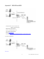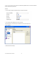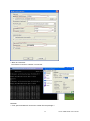
1
WMM-3000R MIMO-G Wireless Broadband Router User’s Manual Declaration of Conformity We, Manufacturer/Importer OvisLink Corp. 5F., NO.6, Lane 130, Min-Chuan Rd., Hsin-Tien City, Taipei County, Taiwan Declare that the product MIMO 802.11g Wireless Broadband Router AirLive WMM-3000R is in conformity with In accordance with 89/336 EEC-EMC Directive and 1999/5 EC-R & TTE Directive Clause Description ■ EN Electromagnetic compatibility and Radio spectrum Matters (ERM); Wideband transmission equipment operating in the 2.4GHz ISM band And using spread spectrum modulation techniques; Part 1:technical Characteristics and test conditions Part2:Harmonized EN covering Essential requirements under article 3.2 of the R&TTE Directive ■ EN Electromagnetic compatibility and Radio spectrum Matters (ERM); Electromagnetic compatibility(EMC) standard for radio equipment and Services; Part 17:Specific conditions for wideband data and HIPERLAN equipment 300 328 V1.6.1 (2004) 301 489-1 V1.4.1 (2002) ■ EN 301 489-17 V1.2.1 (2002) ■ EN 50385:2002 ■ EN 60950-1: 2001 ■ CE marking Product standard to demonstrate the Compliance of radio base stations and Fixed terminal stations for wireless Telecommunication System with the Basic restrictions or the reference levels related to human exposure to radio Frequency electromagnetic fields ( 110 MHz – 40 GHz ) - General public Safety for information technology equipment including electrical Business equipment Manufacturer/Importer Signature: Name : Position/ Title : Albert Yeh Vice President Date: 2006/7/7 (Stamp) AirLive WMM-3000R CE Declaration Statement Country cs Česky [Czech] Declaration OvisLink Corp. tímto prohlašuje, že tento AirLive WMM-3000R je ve shodě se základními požadavky a dalšími příslušnými ustanoveními směrnice 1999/5/ES. da Undertegnede OvisLink Corp. erklærer herved, Dansk [Danish] at følgende udstyr AirLive WMM-3000R overholder de væsentlige krav og øvrige relevante krav i direktiv 1999/5/EF. de Hiermit erklärt OvisLink Corp., dass sich das Deutsch Gerät AirLive WMM-3000R in Übereinstimmung [German] mit den grundlegenden Anforderungen und den übrigen einschlägigen Bestimmungen der Richtlinie 1999/5/EG befindet. et Käesolevaga kinnitab OvisLink Corp. seadme Eesti [Estonian] AirLive WMM-3000R vastavust direktiivi 1999/5/EÜ põhinõuetele ja nimetatud direktiivist tulenevatele teistele asjakohastele sätetele. en Hereby, OvisLink Corp., declares that this AirLive English WMM-3000R is in compliance with the essential requirements and other relevant provisions of Directive 1999/5/EC. es Por medio de la presente OvisLink Corp. declara Español que el AirLive WMM-3000R cumple con los [Spanish] requisitos esenciales y cualesquiera otras disposiciones aplicables o exigibles de la Directiva 1999/5/CE. el ΜΕ ΤΗΝ ΠΑΡΟΥΣΑ OvisLink Corp. ΔΗΛΩΝΕΙ Ελληνική [Greek] ΟΤΙ AirLive WMM-3000R ΣΥΜΜΟΡΦΩΝΕΤΑΙ ΠΡΟΣ ΤΙΣ ΟΥΣΙΩΔΕΙΣ ΑΠΑΙΤΗΣΕΙΣ ΚΑΙ ΤΙΣ ΛΟΙΠΕΣ ΣΧΕΤΙΚΕΣ ΔΙΑΤΑΞΕΙΣ ΤΗΣ ΟΔΗΓΙΑΣ 1999/5/ΕΚ. fr Par la présente OvisLink Corp. déclare que Français [French] l'appareil AirLive WMM-3000R est conforme aux exigences essentielles et aux autres dispositions pertinentes de la directive 1999/5/CE it Con la presente OvisLink Corp. dichiara che Italiano [Italian] questo AirLive WMM-3000R è conforme ai requisiti essenziali ed alle altre disposizioni pertinenti stabilite dalla direttiva 1999/5/CE. lv Ar šo OvisLink Corp. deklarē, ka AirLive WMMLatviski [Latvian] 3000R atbilst Direktīvas 1999/5/EK būtiskajām prasībām un citiem ar to saistītajiem noteikumiem. sv Härmed intygar OvisLink Corp. att denna AirLive Svenska WMM-3000R står I överensstämmelse med de [Swedish] väsentliga egenskapskrav och övriga relevanta bestämmelser som framgår av direktiv 1999/5/EG. Country lt Lietuvių [Lithuanian] Declaration Šiuo OvisLink Corp. deklaruoja, kad šis AirLive WMM-3000R atitinka esminius reikalavimus ir kitas 1999/5/EB Direktyvos nuostatas. nl Hierbij verklaart OvisLink Corp. dat het toestel AirLive Nederlands [Dutch WMM-3000R in overeenstemming is met de essentiële eisen en de andere relevante bepalingen van richtlijn 1999/5/EG. mt Hawnhekk, OvisLink Corp, jiddikjara li dan AirLive Malti [Maltese] WMM-3000R jikkonforma mal-ħtiġijiet essenzjali u ma provvedimenti oħrajn relevanti li hemm fidDirrettiva 1999/5/EC. hu Magyar [Hungarian] pt Português [Portuguese] Az OvisLink Corporation kijelenti, hogy az AirLive WMM-3000R megfelel az 1999/05/CE irányelv alapvető követelményeinek és egyéb vonatkozó rendelkezéseinek. Niniejszym OvisLink Corp oświadcza, że AirLive WMM-3000R jest zgodny z zasadniczymi wymogami oraz pozostałymi stosownymi postanowieniami Dyrektywy 1999/5/EC. OvisLink Corp declara que este AirLive WMM-3000R está conforme com os requisitos essenciais e outras disposições da Directiva 1999/5/CE. sl Slovensko [Slovenian] OvisLink Corp izjavlja, da je ta AirLive WMM-3000R v skladu z bistvenimi zahtevami in ostalimi relevantnimi določili direktive 1999/5/ES. pl Polski [Polish] sk OvisLink Corp týmto vyhlasuje, že AirLive WMMSlovensky [Slovak] 3000R spĺňa základné požiadavky a všetky príslušné ustanovenia Smernice 1999/5/ES. fi Suomi [Finnish] OvisLink Corp vakuuttaa täten että AirLive WMM3000R tyyppinen laite on direktiivin 1999/5/EY oleellisten vaatimusten ja sitä koskevien direktiivin muiden ehtojen mukainen Hér með lýsir OvisLink Corp yfir því að AirLive WMMÍslenska [Icelandic] 3000R er í samræmi við grunnkröfur og aðrar kröfur, sem gerðar eru í tilskipun 1999/5/EC. no OvisLink Corp erklærer herved at utstyret AirLive Norsk [Norwegian] WMM-3000R er i samsvar med de grunnleggende krav og øvrige relevante krav i direktiv 1999/5/EF. A copy of the full CE report can be obtained from the following address: OvisLink Corp. 5F, No.6 Lane 130, Min-Chuan Rd, Hsin-Tien City, Taipei, Taiwan, R.O.C. This equipment may be used in AT, BE, CY, CZ, DK, EE, FI, FR, DE, GR, HU, IE, IT, LV, LT, LU, MT, NL, PL, PT, SK, SI, ES, SE, GB, IS, LI, NO, CH, BG, RO, TR Copyright The contents of this publication may not be reproduced in any part or as a whole, stored, transcribed in an information retrieval system, translated into any language, or transmitted in any form or by any means, mechanical, magnetic, electronic, optical, photocopying, manual, or otherwise, without the prior written permission. Trademarks All products, company, brand names are trademarks or registered trademarks of their respective companies. They are used for identification purpose only. Specifications are subject to be changed without prior notice. FCC Interference Statement This equipment has been tested and found to comply with the limits for a Class B digital device pursuant to Part 15 of the FCC Rules. These limits are designed to provide reasonable protection against radio interference in a commercial environment. This equipment can generate, use and radiate radio frequency energy and, if not installed and used in accordance with the instructions in this manual, may cause harmful interference to radio communications. Operation of this equipment in a residential area is likely to cause interference, in which case the user, at his own expense, will be required to take whatever measures are necessary to correct the interference. CE Declaration of Conformity This equipment complies with the requirements relating to electromagnetic compatibility, EN 55022/A1 Class B. The specification is subject to change without notice. 1 AirLive WMM-3000R User’s Manual Table of Contents CHAPTER 1 INTRODUCTION .................................................................................................................. 4 1-1 FUNCTIONS AND FEATURES......................................................................................................................... 4 1-2 PACKING LIST .............................................................................................................................................. 6 CHAPTER 2 HARDWARE INSTALLATION ............................................................................................. 7 2.1 PANEL LAYOUT ............................................................................................................................................. 7 2.1.1. Front Panel ........................................................................................................................................... 7 2.1.2. Rear Panel ........................................................................................................................................ 8 2.2 PROCEDURE FOR HARDWARE INSTALLATION .............................................................................................. 9 CHAPTER 3 NETWORK SETTINGS AND SOFTWARE INSTALLATION .......................................... 10 3.1 MAKE CORRECT NETWORK SETTINGS OF YOUR COMPUTER .................................................................. 10 CHAPTER 4 CONFIGURING WIRELESS BROADBAND ROUTER ................................................... 11 4.1 START-UP AND LOG IN................................................................................................................................ 12 4.2 STATUS....................................................................................................................................................... 13 4.3 W IZARD ...................................................................................................................................................... 14 4.4 BASIC SETTING .......................................................................................................................................... 15 4.4.1 Primary Setup – WAN Type, Virtual Computers ......................................................................... 15 4.4.2 DHCP Server ................................................................................................................................... 21 4.4.3 Wireless Setting, 802.1X setting and WDS ......................................................................................... 22 4.5 PORT FORWARDING ................................................................................................................................... 30 4.5.1 Virtual Server ................................................................................................................................... 30 4.5.2 Special AP ........................................................................................................................................ 32 4.5.3 Miscellaneous Items ....................................................................................................................... 33 4.6 SECURITY SETTINGS ................................................................................................................................. 34 4.6.1 Packet Filter ..................................................................................................................................... 35 4.6.2 Domain Filter ................................................................................................................................... 40 4.6.3 URL Blocking ................................................................................................................................... 42 4.6.4 MAC Address Control ..................................................................................................................... 44 4.6.5 Miscellaneous Items ....................................................................................................................... 47 4.7 ADVANCED SETTINGS ................................................................................................................................ 48 4.7.1 System Time .................................................................................................................................... 49 4.7.2 System Log ...................................................................................................................................... 50 4.7.3 Dynamic DNS .................................................................................................................................. 51 4.7.4 SNMP Setting .................................................................................................................................. 52 AirLive WMM-3000R User’s Manual 2 4.7.5 Routing ............................................................................................................................................. 53 4.8 MAINTENANCE ........................................................................................................................................... 58 4.8.1 Change Password .......................................................................................................................... 58 4.8.2 System Log .......................................................................................................................................... 59 4.8.3 Firmware Upgrade .......................................................................................................................... 60 4.8.4 Backup Setting ................................................................................................................................ 60 4.8.5 Reset to default ............................................................................................................................... 61 4.8.6 Reboot .............................................................................................................................................. 61 4.8.7 Miscellaneous Items ....................................................................................................................... 61 APPENDIX A TCP/IP CONFIGURATION FOR WINDOWS 95/98 ....................................................... 63 APPENDIX B 802.1X SETTING .............................................................................................................. 68 APPENDIX C WPA-PSK AND WPA ....................................................................................................... 73 APPENDIX D WDS SETTING ................................................................................................................. 84 APPENDIX E FAQ AND TROUBLESHOOTING ................................................................................... 87 3 AirLive WMM-3000R User’s Manual Chapter 1 Introduction Congratulations on your purchase of this outstanding Wireless Broadband Router. This product is specifically designed for Small Office and Home Office needs. It provides a complete SOHO solution for Internet surfing, and is easy to configure and operate even for non-technical users. Instructions for installing and configuring this product can be found in this manual. Before you install and use this product, please read this manual carefully for fully exploiting the functions of this product. 1-1 Functions and Features Router Basic functions Auto-sensing Ethernet Switch Equipped with a 4-port auto-sensing Ethernet switch. WAN type supported The router supports some WAN types, Static, Dynamic, PPPoE , PPTP ,L2TP, Dynamic IP with Road Runner. Firewall All unwanted packets from outside intruders are blocked to protect your Intranet. DHCP server supported All of the networked computers can retrieve TCP/IP settings automatically from this product. Web-based configuring Configurable through any networked computer’s web browser using Netscape or Internet Explorer. Virtual Server supported Enable you to expose WWW, FTP and other services on your LAN to be accessible to Internet users. User-Definable Application Sensing Tunnel User can define the attributes to support the special applications requiring multiple connections, like Internet gaming, video conferencing, Internet telephony and so on, then this product can sense the application type and open multi-port tunnel for it. DMZ Host supported Lets a networked computer be fully exposed to the Internet; this function is used when special application sensing tunnel feature is insufficient to allow an application to function correctly. Statistics of WAN Supported Enables you to monitor inbound and outbound packets AirLive WMM-3000R User’s Manual 4 Wireless functions High speed for wireless LAN connection Up to 54Mbps data rate by incorporating Orthogonal Frequency Division Multiplexing (OFDM). Roaming Provides seamless roaming within the IEEE 802.11b (11M) and IEEE 802.11g (54M) WLAN infrastructure. IEEE 802.11b compatible (11M) Allowing inter-operation among multiple vendors. IEEE 802.11g compatible (54M) Allowing inter-operation among multiple vendors. Auto fallback 54M, 48M, 36M, 24M, 18M, 12M, 6M data rate with auto fallback in 802.11g mode. 11M, 5.5M, 2M, 1M data rate with auto fallback in 802.11b mode. Security functions Packet filter supported Packet Filter allows you to control access to a network by analyzing the incoming and outgoing packets and letting them pass or halting them based on the IP address of the source and destination. Domain Filter Supported Let you prevent users under this device from accessing specific URLs. URL Blocking Supported URL Blocking can block hundreds of websites connection by simply a keyword. VPN Pass-through The router also supports VPN pass-through. 802.1X supported When the 802.1X function is enabled, the Wireless user must authenticate to this router first to use the Network service. Support WPA-PSK and WPA version 1 and 2 When the WPA function is enabled, the Wireless user must authenticate to this router first to use the Network service SPI Mode Supported When SPI Mode is enabled, the router will check every incoming packet to detect if this packet is valid. DoS Attack Detection Supported When this feature is enabled, the router will detect and log the DoS attack comes from the Internet. 5 AirLive WMM-3000R User’s Manual Advanced functions System time Supported Allow you to synchronize system time with network time server. E-mail Alert Supported The router can send its info by mail. Dynamic dns Supported At present,the router has 3 ddns.dyndns,TZO.com and dhs.org. SNMP Supported The router supports basic SNMP function. Routing Table Supported Now, the router supports static routing. Schedule Rule supported Customers can control some functions, like virtual server and packet filters when to access or when to block. Other functions UPNP (Universal Plug and Play)Supported The router also supports this function. The applications: X-box, Msn Messenger. 1-2 Packing List Wireless broadband router unit Installation CD-ROM Power adapter CAT-5 UTP Fast Ethernet cable AirLive WMM-3000R User’s Manual 6 Chapter 2 Hardware Installation 2.1 Panel Layout 2.1.1. Front Panel Figure 2-1 Front Panel LED: Ports: Port Description PWR Power inlet WAN the port where you will connect your cable (or DSL) modem or Ethernet router. Port 1-4 the ports where you will connect networked computers and other devices. 7 AirLive WMM-3000R User’s Manual 2.1.2. Rear Panel Figure 2-2 Rear Panel LED: LED Power Status WAN WLAN Link. 1~4 Function Power indication System status WAN port activity Wireless activity Color Status Description Green On Power is being applied to this product. Green Blinking Green On The WAN port is linked. Blinking The WAN port is sending or receiving data. Blinking Sending or receiving data via wireless Green Link status Green On Blinking Speed 10/100 Data Rate Green On Reset AirLive WMM-3000R User’s Manual Status is flashed once per second to indicate system is alive. An active station is connected to the corresponding LAN port. The corresponding LAN port is sending or receiving data. Data is transmitting in 100Mbps on the corresponding LAN port. To reset system settings to factory defaults 8 2.2 Procedure for Hardware Installation 2. Decide where to place your Wireless Broadband Router You can place your Wireless Broadband Router on a desk or other flat surface, or you can mount it on a wall. For optimal performance, place your Wireless Broadband Router in the center of your office (or your home) in a location that is away from any potential source of interference, such as a metal wall or microwave oven. This location must be close to power and network connection. 2. Setup LAN connection a. Wired LAN connection: connects an Ethernet cable from your computer’s Ethernet port to one of the LAN ports of this product. b. Wireless LAN connection: locate this product at a proper position to gain the best transmit performance. Figure 2-3 Setup of LAN and WAN connections for this product. 3. Setup WAN connection Prepare an Ethernet cable for connecting this product to your cable/xDSL modem or Ethernet backbone. Figure 2-3 illustrates the WAN connection. 4. Power on Connecting the power cord to power inlet and turning the power switch on, this product will automatically enter the self-test phase. When it is in the self-test phase, the indicators M1 will be lighted ON for about 10 seconds, and then M1 will be flashed 3 times to indicate that the self-test operation has finished. Finally, the M1 will be continuously flashed once per second to indicate that this product is in normal operation. 9 AirLive WMM-3000R User’s Manual Chapter 3 Network Settings and Software Installation To use this product correctly, you have to properly configure the network settings of your computers and install the attached setup program into your MS Windows platform (Windows 95/98/NT/2000). 3.1 Make Correct Network Settings of Your Computer The default IP address of this product is 192.168.1.254, and the default subnet mask is 255.255.255.0. These addresses can be changed on your need, but the default values are used in this manual. If the TCP/IP environment of your computer has not yet been configured, you can refer to Appendix A to configure it. For example, 1. configure IP as 192.168.1.1, subnet mask as 255.255.255.0 and gateway as 192.168.1.254, or more easier, 2. configure your computers to load TCP/IP setting automatically, that is, via DHCP server of this product. After installing the TCP/IP communication protocol, you can use the ping command to check if your computer has successfully connected to this product. The following example shows the ping procedure for Windows 95 platforms. First, execute the ping command ping 192.168.1.254 If the following messages appear: Pinging 192.168.1.254 with 32 bytes of data: Reply from 192.168.1.254: bytes=32 time=2ms TTL=64 a communication link between your computer and this product has been successfully established. Otherwise, if you get the following messages, Pinging 192.168.1.254 with 32 bytes of data: Request timed out. There must be something wrong in your installation procedure. You have to check the following items in sequence: 1. Is the Ethernet cable correctly connected between this product and your computer? Tip: The LAN LED of this product and the link LED of network card on your computer must be lighted. 2. Is the TCP/IP environment of your computers properly configured? Tip: If the IP address of this product is 192.168.1.254, the IP address of your computer must be 192.168.1.X and default gateway must be 192.168.1.254. AirLive WMM-3000R User’s Manual 10 Chapter 4 Configuring Wireless Broadband Router This product provides Web based configuration scheme, that is, configuring by your Web browser, such as Netscape Communicator or Internet Explorer. This approach can be adopted in any MS Windows, Macintosh or UNIX based platforms. 11 AirLive WMM-3000R User’s Manual 4.1 Start-up and Log in Activate your browser, and disable the proxy or add the IP address of this product into the exceptions. Then, type this product’s IP address in the Location (for Netscape) or Address (for IE) field and press ENTER. For example: http://192.168.1.254. After the connection is established, you will see the web user interface of this product. There are two appearances of web user interface: for general users and for system administrator. A window would pop-up asking for Login and Password. for password. AirLive WMM-3000R User’s Manual 12 Please enter “admin” for login, and “airlive” 4.2 Status This option provides the function for observing this product’s working status: A. WAN Port Status. If the WAN port is assigned a dynamic IP, there may appear a “Renew” or “Release” button on the Sidenote column. You can click this button to renew or release IP manually. B. Statistics of WAN: enables you to monitor inbound and outbound packets 13 AirLive WMM-3000R User’s Manual 4.3 Wizard Setup Wizard will guide you through a basic configuration procedure step by step.Press ”Next >” Setup Wizard - Select WAN Type: For detail settings, please refer to 4.4.1 primary setup. AirLive WMM-3000R User’s Manual 14 4.4 Basic Setting 4.4.1 Primary Setup – WAN Type, Virtual Computers Press “Change” 15 AirLive WMM-3000R User’s Manual This option is primary to enable this product to work properly. The setting items and the web appearance depend on the WAN type. Choose correct WAN type before you start. 1. LAN IP Address: the local IP address of this device. The computers on your network must use the LAN IP address of your product as their Default Gateway. You can change it if necessary. 2. WAN Type: WAN connection type of your ISP. You can click Change button to choose a correct one from the following four options: A. Static IP Address: ISP assigns you a static IP address. B. Dynamic IP Address: Obtain an IP address from ISP automatically. C. Dynamic IP Address with Road Runner Session Management.(e.g. Telstra BigPond) D. PPP over Ethernet: Some ISPs require the use of PPPoE to connect to their services. E. PPTP: Some ISPs require the use of PPTP to connect to their services. F. L2TP to connect to their services L2TP: Some ISPs require the use of 4.4.1.1 Static IP Address WAN IP Address, Subnet Mask, Gateway, Primary and Secondary DNS: enter the proper setting provided by your ISP. 4.4.1.2 Dynamic IP Address 1. Host Name: optional. Required by some ISPs, for example, @Home. 2. Renew IP Forever: this feature enables this product to renew your IP address automatically when the lease time is expiring-- even when the system is idle. 4.4.1.3 Dynamic IP Address with Road Runner Session Management.(e.g. Telstra BigPond) 1. LAN IP Address is the IP address of this product. It must be the default gateway of your AirLive WMM-3000R User’s Manual 16 computers. 2. WAN Type is Dynamic IP Address. If the WAN type is not correct, change it! 3. Host Name: optional. Required by some ISPs, e.g. @Home. 4. Renew IP Forever: this feature enable this product renew IP address automatically when the lease time is being expired even the system is in idle state. 4.4.1.4 PPP over Ethernet 1. PPPoE Account and Password: the account and password your ISP assigned to you. For security, this field appears blank. If you don't want to change the password, leave it empty. 2. PPPoE Service Name: optional. Input the service name if your ISP requires it. Otherwise, leave it blank. 3. Maximum Idle Time: the amount of time of inactivity before disconnecting your PPPoE session. Set it to zero or enable Auto-reconnect to disable this feature. 4. Maximum Transmission Unit (MTU): Most ISP offers MTU value to users. The most common MTU value is 1492. 5. Connection Control:There are 3 modes to select: Connect-on-demand:The device will link up with ISP when the clients send outgoing packets. Auto-Reconnect(Always-on):The device will link upw with ISP until the connection is established. Manually:The device will not make the link until someone clicks the connect-button in the Staus-page. 4.4.1.5 PPTP First,Please check your ISP assigned and Select Static IP Address or Dynamic IP Address. 1. My IP Address and My Subnet Mask: the private IP address and subnet mask your ISP assigned to you. 2. Server IP Address: the IP address of the PPTP server. 17 AirLive WMM-3000R User’s Manual 3. PPTP Account and Password: the account and password your ISP assigned to you. If you don't want to change the password, keep it empty. 3. Connection ID: optional. Input the connection ID if your ISP requires it. 4. Maximum Idle Time: the time of no activity to disconnect your PPTP session. Set it to zero or enable Auto-reconnect to disable this feature. If Auto-reconnect is enabled, this product will connect to ISP automatically, after system is restarted or connection is dropped. 5. Connection Control:There are 3 modes to select: Connect-on-demand:The device will link up with ISP when the clients send outgoing packets. Auto-Reconnect(Always-on):The device will link upw with ISP until the connection is established. Manually:The device will not make the link until someone clicks the connect-button in the Staus-page. AirLive WMM-3000R User’s Manual 18 4.4.1.6 L2TP First,Please check your ISP assigned and Select Static IP Address or Dynamic IP Address. For example:Use Static 1. My IP Address and My Subnet Mask: the private IP address and subnet mask your ISP assigned to you. 2. Server IP Address: the IP address of the PPTP server. 3. PPTP Account and Password: the account and password your ISP assigned to you. If you don't want to change the password, keep it empty. 3. Connection ID: optional. Input the connection ID if your ISP requires it. 4. Maximum Idle Time: the time of no activity to disconnect your PPTP session. Set it to zero or enable Auto-reconnect to disable this feature. If Auto-reconnect is enabled, this product will connect to ISP automatically, after system is restarted or connection is dropped. 6. Connection Control:There are 3 modes to select: Connect-on-demand:The device will link up with ISP when the clients send outgoing packets. Auto-Reconnect(Always-on):The device will link upw with ISP until the connection is established. Manually:The device will not make the link until someone clicks the connect-button in the Staus-page. 19 AirLive WMM-3000R User’s Manual AirLive WMM-3000R User’s Manual 20 4.4.1.7 Virtual Computers(Only for Static and dynamic IP address Wan type) Virtual Computer enables you to use the original NAT feature, and allows you to setup the one-to-one mapping of multiple global IP address and local IP address. Global IP: Enter the global IP address assigned by your ISP. Local IP: Enter the local IP address of your LAN PC corresponding to the global IP address. Enable: Check this item to enable the Virtual Computer feature. 4.4.2 DHCP Server Press “More>>” The settings of a TCP/IP environment include host IP, Subnet Mask, Gateway, and DNS configurations. It is not easy to manually configure all the computers and devices in your network. Fortunately, DHCP Server provides a rather simple approach to handle all these settings. This product supports the 21 AirLive WMM-3000R User’s Manual function of DHCP server. If you enable this product’s DHCP server and configure your computers as “automatic IP allocation” mode, then when your computer is powered on, it will automatically load the proper TCP/IP settings from this product. The settings of DHCP server include the following items: 1. DHCP Server: Choose “Disable” or “Enable.” 2. IP pool starting Address/ IP pool starting Address: Whenever there is a request, the DHCP server will automatically allocate an unused IP address from the IP address pool to the requesting computer. You must specify the starting and ending address of the IP address pool. 3. Domain Name: Optional, this information will be passed to the client. 4. Primary DNS/Secondary DNS: This feature allows you to assign DNS Servers 5. Primary WINS/Secondary WINS: This feature allows you to assign WINS Servers 6. Gateway: The Gateway Address would be the IP address of an alternate Gateway. This function enables you to assign another gateway to your PC, when DHCP server offers an IP to your PC. 4.4.3 Wireless Setting, 802.1X setting and WDS AirLive WMM-3000R User’s Manual 22 Wireless settings allow you to set the wireless configuration items. 1. Wireless : The user can enable or disalbe wireless function. 2. Network ID (SSID): Network ID is used for identifying the Wireless LAN (WLAN). Client stations can roam freely over this product and other Access Points that have the same Network ID. (The factory setting is “default”) 3. Channel: The radio channel number. The permissible channels depend on the Regulatory Domain. The factory setting is as follow: channel 6 for North America; channel 7 for European (ETSI); channel 7 for Japan. 4. WEP Security: Select the data privacy algorithm you want. Enabling the security can protect your data while it is transferred from one station to another. The standardized IEEE 802.11 WEP (128 or 64-bit) is used here. 5. WEP Key 1, 2, 3 & 4: When you enable the 128 or 64 bit WEP key security, please select one WEP key to be used and input 26 or 10 hexadecimal (0, 1, 2…8, 9, A, B…F) digits. 6. Pass-phrase Generator: Since hexadecimal characters are not easily remembered, this device offers a conversion utility to convert a simple word or phrase into hex. 6. 802.1X Setting 802.1X Check Box was used to switch the function of the 802.1X. When the 802.1X function is enabled, the Wireless user must authenticate to this router first to use the Network service. RADIUS Server IP address or the 802.1X server’s domain-name. RADIUS Shared Key Key value shared by the RADIUS server and this router. This key value is consistent with the key value in the RADIUS server. 23 AirLive WMM-3000R User’s Manual WPA-PSK 1. Select Encryntion and Preshare Key Mode If you select HEX,you have to fill in 64 hexadecimal (0, 1, 2…8, 9, A, B…F) digits If ASCII,the length of preshare key is from 8 to 63. 2. Fill in the key, Ex 12345678 AirLive WMM-3000R User’s Manual 24 WPA Check Box was used to switch the function of the WPA. When the WPA function is enabled, the Wireless user must authenticate to this router first to use the Network service. RADIUS Server IP address or the 802.1X server’s domain-name. Select Encryption and RADIUS Shared Key If you select HEX,you have to fill in 64 hexadecimal (0, 1, 2…8, 9, A, B…F) digits If ASCII,the length of preshare key is from 8 to 63. Key value shared by the RADIUS server and this router. This key value is consistent with the key value in the RADIUS server. WPA2-PSK(AES) 1. Select Pre-share Key Mode If you select HEX, you have to fill in 64 hexadecimal (0, 1, 2…8, 9, A, B…F) digits If ASCII, the length of Pre-share key is from 8 to 63. 2. Fill in the key, Ex 12345678 25 AirLive WMM-3000R User’s Manual WPA2(AES) Check Box was used to switch the function of the WPA. When the WPA function is enabled, the Wireless user must authenticate to this router first to use the Network service. RADIUS Server IP address or the 802.1X server’s domain-name. Select RADIUS Shared Key If you select HEX, you have to fill in 64 hexadecimal (0, 1, 2…8, 9, A, B…F) digits If ASCII, the length of Pre-share key is from 8 to 63. Key value shared by the RADIUS server and this router. This key value is consistent with the key value in the RADIUS server. AirLive WMM-3000R User’s Manual 26 WPA-PSK /WPA2-PSK The router will detect automatically which Security type(Wpa-psk version 1 or 2) the client uses to encrypt. 1. Select Pre-share Key Mode If you select HEX, you have to fill in 64 hexadecimal (0, 1, 2…8, 9, A, B…F) digits If ASCII, the length of Pre-share key is from 8 to 63. 2. Fill in the key, Ex 12345678 27 AirLive WMM-3000R User’s Manual WPA/WPA2 Check Box was used to switch the function of the WPA. When the WPA function is enabled, the Wireless user must authenticate to this router first to use the Network service. RADIUS Server The router will detect automatically which Security type(Wpa-psk version 1 or 2) the client uses to encrypt. IP address or the 802.1X server’s domain-name. Select RADIUS Shared Key If you select HEX, you have to fill in 64 hexadecimal (0, 1, 2…8, 9, A, B…F) digits If ASCII, the length of Pre-share key is from 8 to 63. Key value shared by the RADIUS server and this router. This key value is consistent with the key value in the RADIUS server. AirLive WMM-3000R User’s Manual 28 WDS(Wireless Distribution System) WDS operation as defined bythe IEEE802.11 standard has been made available. Using WDS it is possible to wirelessly connect Access Points, and in doing so extend a wired infrastructure to locations where cabling is not possible or inefficient to implement. 29 AirLive WMM-3000R User’s Manual 4.5 Port Forwarding 4.5.1 Virtual Server This product’s NAT firewall filters out unrecognized packets to protect your Intranet, so all hosts behind this product are invisible to the outside world. If you wish, you can make some of them accessible by enabling the Virtual Server Mapping. A virtual server is defined as a Service Port, and all requests to this port will be redirected to the computer specified by the Server IP. Virtual Server can work with Scheduling Rules, and give user more flexibility on Access control. For Detail, please refer to Scheduling Rule. AirLive WMM-3000R User’s Manual 30 For example, if you have an FTP server (port 21) at 192.168.1.1, a Web server (port 80) at 192.168.1.2, and a VPN server at 192.168.1.6, then you need to specify the following virtual server mapping table: Service Port Server IP Enable 21 192.168.1.1 V 80 192.168.1.2 V 1723 192.168.1.6 V 31 AirLive WMM-3000R User’s Manual 4.5.2 Special AP Some applications require multiple connections, like Internet games, Video conferencing, Internet telephony, etc. Because of the firewall function, these applications cannot work with a pure NAT router. The Special Applications feature allows some of these applications to work with this product. If the mechanism of Special Applications fails to make an application work, try setting your computer as the DMZ host instead. 1. Trigger: the outbound port number issued by the application.. 2. Incoming Ports: when the trigger packet is detected, the inbound packets sent to the specified port numbers are allowed to pass through the firewall. This product provides some predefined settings Select your application and click Copy to to add the predefined setting to your list. Note! At any given time, only one PC can use each Special Application tunnel. AirLive WMM-3000R User’s Manual 32 4.5.3 Miscellaneous Items IP Address of DMZ Host DMZ (DeMilitarized Zone) Host is a host without the protection of firewall. It allows a computer to be exposed to unrestricted 2-way communication for Internet games, Video conferencing, Internet telephony and other special applications. NOTE: This feature should be used only when needed. Non-standard FTP port You have to configure this item if you want to access an FTP server whose port number is not 21. This setting will be lost after rebooting. UpnP Setting The device also supports this function.If the OS supports this function enable it,like Windows Xp.When the user get ip from Device and will see icon as below: 33 AirLive WMM-3000R User’s Manual 4.6 Security Settings AirLive WMM-3000R User’s Manual 34 4.6.1 Packet Filter Packet Filter enables you to control what packets are allowed to pass the router. Outbound filter applies on all outbound packets. However, Inbound filter applies on packets that destined to Virtual Servers or DMZ host only. You can select one of the two filtering policies: 1. Allow all to pass except those match the specified rules 2. Deny all to pass except those match the specified rules You can specify 8 rules for each direction: inbound or outbound. For each rule, you can define the following: Source IP address Source port address Destination IP address Destination port address Protocol: TCP or UDP or both. Use Rule# 35 AirLive WMM-3000R User’s Manual For source or destination IP address, you can define a single IP address (4.3.2.1) or a range of IP addresses (4.3.2.1-4.3.2.254). An empty implies all IP addresses. For source or destination port, you can define a single port (80) or a range of ports (1000-1999). Add prefix "T" or "U" to specify TCP or UDP protocol. For example, T80, U53, U2000-2999. No prefix indicates both TCP and UDP are defined. An empty implies all port addresses. Packet Filter can work with Scheduling Rules, and give user more flexibility on Access control. For Detail, please refer to Scheduling Rule. Each rule can be enabled or disabled individually. Inbound Filter: To enable Inbound Packet Filter click the check box next to Enable in the Inbound Packet Filter field. Suppose you have SMTP Server (25), POP Server (110), Web Server (80), FTP Server (21), and News Server (119) defined in Virtual Server or DMZ Host. Example 1: AirLive WMM-3000R User’s Manual 36 (1.2.3.100-1.2.3.149) They are allow to send mail (port 25), receive mail (port 110), and browse the Internet (port 80) (1.2.3.10-1.2.3.20) They can do everything (block nothing) Others are all blocked. Example 2: (1.2.3.100-1.2.3.119) They can do everything except read net news (port 119) and transfer files via FTP (port 21) Others are all allowed. After Inbound Packet Filter setting is configured, click the save button. Outbound Filter: 37 AirLive WMM-3000R User’s Manual To enable Outbound Packet Filter click the check box next to Enable in the Outbound Packet Filter field. Example 1: (192.168.1.100-192.168.1.149) They are allowed to send mail (port 25), receive mail (port 110), and browse Internet (port 80); port 53 (DNS) is necessary to resolve the domain name. (192.168.1.10-192.168.1.20) They can do everything (block nothing) Others are all blocked. AirLive WMM-3000R User’s Manual 38 Example 2: (192.168.1.100-192.168.1.119) They can do everything except read net news (port 119) and transfer files via FTP (port 21) Others are allowed After Outbound Packet Filter setting is configured, click the save button. 39 AirLive WMM-3000R User’s Manual 4.6.2 Domain Filter Domain Filter Let you prevent users under this device from accessing specific URLs. Domain Filter Enable Check if you want to enable Domain Filter. Log DNS Query Check if you want to log the action when someone accesses the specific URLs. Privilege IP Addresses Range Setting a group of hosts and privilege these hosts to access network without restriction. Domain Suffix A suffix of URL to be restricted. For example, ".com", "xxx.com". Action When someone is accessing the URL met the domain-suffix, what kind of action you want. Check drop to block the access. Check log to log these access. Enable Check to enable each rule. AirLive WMM-3000R User’s Manual 40 Example: In this example: 1. URL include “www.msn.com” will be blocked, and the action will be record in log-file. 2. URL include “www.sina.com” will not be blocked, but the action will be record in log-file. 3. URL include “www.google.com” will be blocked, but the action will not be record in log-file. 4. IP address X.X.X.1~ X.X.X.20 can access network without restriction. 41 AirLive WMM-3000R User’s Manual 4.6.3 URL Blocking URL Blocking will block LAN computers to connect to pre-defined Websites. The major difference between “Domain filter” and “URL Blocking” is Domain filter require user to input suffix (like .com or .org, etc), while URL Blocking require user to input a keyword only. In other words, Domain filter can block specific website, while URL Blocking can block hundreds of websites by simply a keyword. URL Blocking Enable Checked if you want to enable URL Blocking. URL If any part of the Website's URL matches the pre-defined word, the connection will be blocked. For example, you can use pre-defined word "sex" to block all websites if their URLs contain pre-defined word "sex". Enable Checked to enable each rule. AirLive WMM-3000R User’s Manual 42 In this example: 1. URL include “msn” will be blocked, and the action will be record in log-file. 2. URL include “sina” will be blocked, but the action will be record in log-file 3. URL include “cnnsi” will not be blocked, but the action will be record in log-file. 4. URL include “espn” will be blocked, but the action will be record in log-file 43 AirLive WMM-3000R User’s Manual 4.6.4 MAC Address Control MAC Address Control allows you to assign different access right for different users and to assign a specific IP address to a certain MAC address. MAC Address Control Check “Enable” to enable the “MAC Address Control”. All of the settings in this page will take effect only when “Enable” is checked. Connection control Check "Connection control" to enable the controlling of which wired and wireless clients can connect to this device. If a client is denied to connect to this device, it means the client can't access to the Internet either. Choose "allow" or "deny" to allow or deny the clients, whose MAC addresses are not in the "Control table" (please see below), to connect to this device. Association control Check "Association control" to enable thecontrolling of which wireless client can associate to the wireless LAN. If a client is denied to associate to the wireless LAN, itmeans the client can't send or receive any data via this device. Choose "allow" or "deny" to allow or deny the clients, whose MAC addresses are not in the "Control table", to associate to the wireless LAN. AirLive WMM-3000R User’s Manual 44 Control table "Control table" is the table at the bottom of the "MAC Address Control" page. Each row of this table indicates the MAC address and the expected IP address mapping of a client. There are four columns in this table: MAC Address IP Address MAC address indicates a specific client. Expected IP address of the corresponding client. Keep it empty if you don't care its IP address. C When "Connection control" is checked, check "C" will allow the corresponding client to connect to this device. A When "Association control" is checked, check "A" will allow the corresponding client to associate to the wireless LAN. In this page, we provide the following Combobox and button to help you to input the MAC address. You can select a specific client in the “DHCP clients” Combobox, and then click on the “Copy to” button to copy the MAC address of the client you select to the ID selected in the “ID” Combobox. Previous page and Next Page To make this setup page simple and clear, we have divided the “Control table” into several pages. You can use these buttons to navigate to different pages. 45 AirLive WMM-3000R User’s Manual Example: In this scenario, there are three clients listed in the Control Table. Clients 1 and 2 are wireless, and client 3 is wired. 1.The "MAC Address Control" function is enabled. 2."Connection control" is enabled, and all of the wired and wireless clients not listed in the "Control table" are "allowed" to connect to this device. 3."Association control" is enabled, and all of the wireless clients not listed in the "Control table" are "denied" to associate to the wireless LAN. 4.Clients 1 and 3 have fixed IP addresses either from the DHCP server of this device or manually assigned: ID 1 - "00-12-34-56-78-90" --> 192.168.1.100 ID 3 - "00-98-76-54-32-10" --> 192.168.1.101 Client 2 will obtain its IP address from the IP Address pool specified in the "DHCP Server" page or can use a manually assigned static IP address. If, for example, client 3 tries to use an IP address different from the address listed in the Control table (192.168.1.101), it will be denied to connect to this device. 5.Clients 2 and 3 and other wired clients with a MAC address unspecified in the Control table are all AirLive WMM-3000R User’s Manual 46 allowed to connect to this device. But client 1 is denied to connect to this device. 6.Clients 1 and 2 are allowed to associate to the wireless LAN, but a wireless client with a MAC address not specified in the Control table is denied to associate to the wireless LAN. Client 3 is a wired client and so is not affected by Association control. 4.6.5 Miscellaneous Items Remote Administrator Host/Port In general, only Intranet user can browse the built-in web pages to perform administration task. This feature enables you to perform administration task from remote host. If this feature is enabled, only the specified IP address can perform remote administration. If the specified IP address is 0.0.0.0, any host can connect to this product to perform administration task. You can use subnet mask bits "/nn" notation to specified a group of trusted IP addresses. For example, "10.1.2.0/24". NOTE: When Remote Administration is enabled, the web server port will be shifted to 88. You can change web server port to other port, too. Administrator Time-out The time of no activity to logout automatically. Set it to zero to disable this feature. Discard PING from WAN side When this feature is enabled, any host on the WAN cannot ping this product. SPI Mode When this feature is enabled, the router will record the packet information pass through the router like IP address, port address, ACK, SEQ number and so on. And the router will check every incoming packet to detect if this packet is valid. DoS Attack Detection When this feature is enabled, the router will detect and log the DoS attack comes from the Internet. Currently, the router can detect the following DoS attack: SYN Attack, WinNuke, Port Scan, Ping of Death, Land Attack etc. 47 AirLive WMM-3000R User’s Manual 4.7 Advanced Settings AirLive WMM-3000R User’s Manual 48 4.7.1 System Time Get Date and Time by NTP Protocol Selected if you want to Get Date and Time by NTP Protocol. Time Server Select a NTP time server to consult UTC time Time Zone Select a time zone where this device locates. Set Date and Time manually Selected if you want to Set Date and Time manually. Set Date and Time manually Selected if you want to Set Date and Time manually. Function of Buttons Sync Now: Synchronize system time with network time server Daylight Saving:Set up where the location is. 49 AirLive WMM-3000R User’s Manual 4.7.2 System Log This page support two methods to export system logs to specific destination by means of syslog(UDP) and SMTP(TCP). The items you have to setup including: IP Address for Syslog Host IP of destination where syslogs will be sent to. Check Enable to enable this function. E-mail Alert Enable Check if you want to enable Email alert (send syslog via email). SMTP Server IP and Port Input the SMTP server IP and port, which are concated with ':'. If you do not specify port number, the default value is 25. For example, "mail.your_url.com" or "192.168.1.100:26". Send E-mail alert to The recipients who will receive these logs. You can assign more than 1 recipient, using ';' or ',' to separate these email addresses. AirLive WMM-3000R User’s Manual 50 4.7.3 Dynamic DNS To host your server on a changing IP address, you have to use dynamic domain name service (DDNS). So that anyone wishing to reach your host only needs to know the name of it. Dynamic DNS will map the name of your host to your current IP address, which changes each time you connect your Internet service provider. Before you enable Dynamic DNS, you need to register an account on one of these Dynamic DNS servers that we list in provider field. To enable Dynamic DNS click the check box next to Enable in the DDNS field. Next you can enter the appropriate information about your Dynamic DNS Server. You have to define: Provider Host Name Username/E-mail Password/Key You will get this information when you register an account on a Dynamic DNS server. Example: 51 AirLive WMM-3000R User’s Manual After Dynamic DNS setting is configured, click the save button. 4.7.4 SNMP Setting In brief, SNMP, the Simple Network Management Protocol, is a protocol designed to give a user the capability to remotely manage a computer network by polling and setting terminal values and monitoring network events. Enable SNMP You must check either Local or Remote or both to enable SNMP function. If Local is checked, this device will response request from LAN. If Remote is checked, this device will response request from WAN. Get Community Setting the community of GetRequest your device will response. AirLive WMM-3000R User’s Manual 52 Set Community Setting the community of SetRequest your device will accept. WAN Access IP Address IF the user wants to limit to specific the ip address to access,please input in the item.The default 0.0.0.0 and means every ip of Internet can get some information of device with snmp protocol. 4.7.5 Routing Routing Tables allow you to determine which physical interface address to use for outgoing IP data grams. If you have more than one routers and subnets, you will need to enable routing table to allow packets to find proper routing path and allow different subnets to communicate with each other. Routing Table settings are settings used to setup the functions of static. Static Routing: For static routing, you can specify up to 8 routing rules. You can enter the destination IP address, subnet mask, gateway, hop for each routing rule, and then enable or disable the rule by checking or unchecking the Enable checkbox. 53 AirLive WMM-3000R User’s Manual Example: Configuration on NAT Router Destination SubnetMask Gateway Hop Enabled 192.168.1.0 255.255.255.0 192.168.1.216 1 ˇ 192.168.0.0 255.255.255.0 192.168.1.103 1 ˇ So if, for example, the client3 wanted to send an IP data gram to 192.168.0.2, it would use the above table to determine that it had to go via 192.168.1.103 (a gateway), And if it sends Packets to 192.168.1.11 will go via 192.168.1.216 Each rule can be enabled or disabled individually. After routing table setting is configured, click the save button. AirLive WMM-3000R User’s Manual 54 4.7.6 Schedule Rule You can set the schedule time to decide which service will be turned on or off. Select the “enable” item. Press “Add New Rule” You can write a rule name and set which day and what time to schedule from “Start Time” to “End Time”. The following example configure “ftp time” as everyday 14:10 to 16:20 55 AirLive WMM-3000R User’s Manual After configure Rule 1 Schedule Enable Selected if you want to Enable the Scheduler. Edit To edit the schedule rule. Delete To delete the schedule rule, and the rule# of the rules behind the deleted one will decrease one automatically. Schedule Rule can be apply to Virtual server and Packet Filter, for example: Exanple1: Virtual Server – Apply Rule#1 (ftp time: everyday 14:10 to 16:20) AirLive WMM-3000R User’s Manual 56 Exanple2: Packet Filter – Apply Rule#1 (ftp time: everyday 14:10 to 16:20). 57 AirLive WMM-3000R User’s Manual 4.8 Maintenance 4.8.1 Change Password You can change Password here. We strongly recommend you to change the system password for security reason. AirLive WMM-3000R User’s Manual 58 4.8.2 System Log You can View system log by clicking the View Log button 59 AirLive WMM-3000R User’s Manual 4.8.3 Firmware Upgrade You can upgrade firmware by clicking Firmware Upgrade button. 4.8.4 Backup Setting You can backup your settings by clicking the Backup Setting button and save it as a bin file. Once you want to restore these settings, please click Firmware Upgrade button and use the bin file you saved. AirLive WMM-3000R User’s Manual 60 4.8.5 Reset to default You can also reset this product to factory default by clicking the Reset to default button. 4.8.6 Reboot You can also reboot this product by clicking the Reboot button. 4.8.7 Miscellaneous Items 61 AirLive WMM-3000R User’s Manual MAC Address for Wake-on-LAN Wake-on-LAN is a technology that enables you to power up a networked device remotely. In order to enjoy this feature, the target device must be Wake-on-LAN enabled and you have to know the MAC address of this device, say 00-11-22-33-44-55. Clicking "Wake up" button will make the router to send the wake-up frame to the target device immediately. Domain Name or IP Address for Ping Test Allow you to configure an IP, and ping the device. You can ping a secific IP to test whether it is alive. AirLive WMM-3000R User’s Manual 62 Appendix A TCP/IP Configuration for Windows 95/98 This section introduces you how to install TCP/IP protocol into your personal computer. And suppose you have been successfully installed one network card on your personal computer. If not, please refer to your network card manual. Moreover, the Section B.2 tells you how to set TCP/IP values for working with this NAT Router correctly. A.1 Install TCP/IP Protocol into Your PC 1. Click Start button and choose Settings, then click Control Panel. 2. Double click Network icon and select Configuration tab in the Network window. 3. Click Add button to add network component into your PC. 4. Double click Protocol to add TCP/IP protocol. 5. Select Microsoft item in the manufactures list. And choose TCP/IP in the Network Protocols. Click OK button to return to Network window. 63 AirLive WMM-3000R User’s Manual 6. The TCP/IP protocol shall be listed in the Network window. Click OK to complete the install procedure and restart your PC to enable the TCP/IP protocol. A.2 Set TCP/IP Protocol for Working with NAT Router 1. Click Start button and choose Settings, then click Control Panel. 2. Double click Network icon. Select the TCP/IP line that has been associated to your network card in the Configuration tab of the Network window. 3. Click Properties button to set the TCP/IP protocol for this NAT Router. 4. Now, you have two setting methods: AirLive WMM-3000R User’s Manual 64 a. Select Obtain an IP address automatically in the IP Address tab. b. Don’t input any value in the Gateway tab. 65 AirLive WMM-3000R User’s Manual c. Choose Disable DNS in the DNS Configuration tab. B. Configure IP manually a. Select Specify an IP address in the IP Address tab. The default IP address of this product is 192.168.1.254. So please use 192.168.1.xxx (xxx is between 1 and 253) for IP Address field and 255.255.255.0 for Subnet Mask field. AirLive WMM-3000R User’s Manual 66 b. In the Gateway tab, add the IP address of this product (default IP is 192.168.1.254) in the New gateway field and click Add button. c. In the DNS Configuration tab, add the DNS values which are provided by the ISP into DNS Server Search Order field and click Add button. 67 AirLive WMM-3000R User’s Manual Appendix B 802.1x Setting Figure 1: Testing Environment (Use Windows 2000 Radius Server) 1 Equipment Details PC1: Microsoft Windows XP Professional without Service Pack 1. AMIT 531C Wireless Cardbus:3.0.3.0 Driver version: PC2: Microsoft Windows XP Professional with Service Pack 1a or latter. AMIT 561C Wireless Cardbus:1.0.1.0 Driver version: 1.7.29.0 (Driver date: 10.20.2001) Authentication Server: Windows 2000 RADIUS server with Service Pack 3 and HotFix Q313664. Note. Windows 2000 RADIUS server only supports PEAP after upgrade to service pack 3 and HotFix Q313664 (You can get more information from http://support.microsoft.com/default.aspx?scid=kb; en-us;313664) 2 DUT Configuration: 1.Enable DHCP server. 2.WAN setting: static IP address. 3.LAN IP address: 192.168.1.254/24. 4.Set RADIUS server IP. AirLive WMM-3000R User’s Manual 68 5.Set RADIUS server shared key. 6.Configure WEP key and 802.1X setting. The following test will use the inbuilt 802.1X authentication method such as ,EAP_TLS, PEAP_CHAPv2(Windows XP with SP1 only), and PEAP_TLS(Windows XP with SP1 only) using the Smart Card or other Certificate of the Windows XP Professional. 3. DUT and Windows 2000 Radius Server Setup 3-1-1. Setup Windows 2000 RADIUS Server We have to change authentication method to MD5_Challenge or using smart card or other certificate on RADIUS server according to the test condition. 3-1-2. Setup DUT 1.Enable the 802.1X (check the “Enable checkbox“). 2.Enter the RADIUS server IP. 3.Enter the shared key. (The key shared by the RADIUS server and DUT). 4.We will change 802.1X encryption key length to fit the variable test condition. 3-1-3. Setup Network adapter on PC 1.Choose the IEEE802.1X as the authentication method. (Fig 2) Note. Figure 2 is a setting picture of Windows XP without service pack 1. If users upgrade to service pack 1, then they can’t see MD5-Challenge from EAP type list any more, but they will get a new Protected EAP (PEAP) option. 2.Choose MD5-Challenge or Smart Card or other Certificate as the EAP type. 3.If choosing use smart card or the certificate as the EAP type, we select to use a certificate on this computer. (Fig 3) 4. We will change EAP type to fit the variable test condition. 69 AirLive WMM-3000R User’s Manual Figure 2: Enable IEEE 802.1X access control 4. Windows 2000 RADIUS server Authentication testing: 4.1DUT authenticate PC1 using certificate. (PC2 follows the same test procedures.) 1. Download and install the certificate on PC1. (Fig 4) 2. PC1 choose the SSID of DUT as the Access Point. 3. Set authentication type of wireless client and RADIUS server both to EAP_TLS. 4. Disable the wireless connection and enable again. 5. The DUT will send the user's certificate to the RADIUS server, and then send the message of authentication result to PC1. (Fig 5) 6. Windows XP will prompt that the authentication process is success or fail and end the authentication procedure. ( Fig 6) AirLive WMM-3000R User’s Manual 70 7. Terminate the test steps when PC1 get dynamic IP and PING remote host successfully. Figure 4: Certificate information on PC1 Figure 5: Authenticating 71 AirLive WMM-3000R User’s Manual Figure 6: Authentication success 4.2DUT authenticate PC2 using PEAP-TLS. 1. PC2 choose the SSID of DUT as the Access Point. 2. Set authentication type of wireless client and RADIUS server both to PEAP_TLS. 3. Disable the wireless connection and enable again. 4.The DUT will send the user's certificate to the RADIUS server, and then send the message of authentication result to PC2. 5. Windows XP will prompt that the authentication process is success or fail and end the authentication procedure. 6. Terminate the test steps when PC2 get dynamic IP and PING remote host successfully. Support Type: The router supports the types of 802.1x Authentication: PEAP-CHAPv2 and PEAP-TLS. Note. 1.PC1 is on Windows XP platform without Service Pack 1. 2.PC2 is on Windows XP platform with Service Pack 1a. 3.PEAP is supported on Windows XP with Service Pack 1 only. 4.Windows XP with Service Pack 1 allows 802.1x authentication only when data encryption function is enable. AirLive WMM-3000R User’s Manual 72 Appendix C WPA-PSK and WPA Wireless Router: LAN IP: 192.168.1.254 WAN IP: 192.168.122.216 Radius Server: 192.168.122.1 UserA : XP Wireless Card:Ti-11g Tool: Odyssey Client Manager Refer to: www.funk.com Download: http://www.funk.com/News&Events/ody_c_wpa_preview_pn.asp Or Another Configuration: WPA-PSK 73 AirLive WMM-3000R User’s Manual In fact, it is not necessary for this function to authenticate by Radius Server, the client and wireless Router authenticate by themselves. Method1: 1. Go to the Web manager of Wireless Router to configure, like below: 2. Go to Odyssey Client Manager, first choose “Network” Before doing that, you should verify if the software can show the wireless card. Open “Adapters” 3. Add and edit some settings: AirLive WMM-3000R User’s Manual 74 4. Back to Connection: Then Select “Connect to network” You will see: Method2: 1. First, patch windows XP and have to install “Service package 1” 75 AirLive WMM-3000R User’s Manual Patch: http://www.microsoft.com/downloads/details.aspx?displaylang=en&FamilyID=5039ef4a-61e0-4c4494f0-c25c9de0ace9 2. Then reboot. 3. Setting on the router and client: Router: Client: Go to “Network Connection” and select wireless adapter. Choose “View available Wireless Networks” like below: Advanced choose “123kk” AirLive WMM-3000R User’s Manual 76 WPA: For this function, we need the server to authenticate. This function is like 802.1x. The above is our environment: Method 1: 1. The UserA or UserB have to get certificate from Radius, first. http://192.168.122.1/certsrv account : fae1 passwd : fae1 2. Then, Install this certificate and finish. 3. Go to the Web manager of Wireless Router to configure, like below: 77 AirLive WMM-3000R User’s Manual 4. Go to Odyssey Client Manager, choose “Profiles” and Setup Profile name as “1” Login name and passwd are fae1 and fae1. Remember that you get certificate from Radius in Step1. AirLive WMM-3000R User’s Manual 78 5. Then Choose “certificate” like above. 6. Then go to Authentication and first Remove EAP/ TLS and Add EAP/TLS again. 79 AirLive WMM-3000R User’s Manual 7. Go “Network” and Select “1” and ok 8. Back to Connection and Select “123kk. If successfully, the wireless client has to authenticate with Radius Server, like below: AirLive WMM-3000R User’s Manual 80 9.Result: Method 2: 1. The UserA or UserB have to get certificate from Radius,first. http://192.168.122.1/certsrv account:fae1 passwd:fae1 81 AirLive WMM-3000R User’s Manual 2. Then Install this certificate and finish. 3. Setting on the router and client: Router: Client: Go to “Network Connection” and select wireless adapter. Choose “View available Wireless Networks” like below: Advanced choose “123kk” Select “WirelessCA and Enable” in Trusted root certificate authority: AirLive WMM-3000R User’s Manual 82 Then, if the wireless client wants to associate, it has to request to authenticate. 83 AirLive WMM-3000R User’s Manual Appendix D WDS Setting How to setup and work: First, check the Wlan-mac address of AP1,AP2 and AP3.Please goto command mode and use “Arp –a ”. If you can not find the information of Mac, please make the cable to plug in lan-port of ap and ping the lan ip address then arp –a. There are some information in the screen. For example: AP 1: AP2: AP3: IP:192.168.1.254 IP:192.168.1.253 IP:192.168.1.252 Mac:00-50-18-00-0f-fe Mac:00-50-18-00-0f-fd SSID:Default SSID:Default SSID:Default Channel:11 Channel:11 Channel:11 Dhcp Server:Enable Blue Line:Wireless Black Line:Wire AirLive WMM-3000R User’s Manual 84 Mac:00-50-18-00-0f-fc If the Settings are ok,the client1 and client2 can get ip from dhcp server of AP1.Then Client1 and Client2 can get information each other. AP1 Setting: AP1 AP2(Remote Mac: 00-50-18-00-0f-fd) AP1 AP3(Remote Mac: 00-50-18-00-0f-fc) 85 AirLive WMM-3000R User’s Manual AP2 Setting: AP2 AP1(Remote Mac: 00-50-18-00-0f-fe) AP3 Setting AP3 AP1(Remote Mac: 00-50-18-00-0f-fe) AirLive WMM-3000R User’s Manual 86 Appendix E FAQ and Troubleshooting What can I do when I have some trouble at the first time? 1. Why can I not configure the router even if the cable is plugged in the ports of Router and the led is also light? A: First, make sure that which port is plugged. If the cable is in the Wan port, please change to plug in Lan port 1 or Lan port 4: Then, please check if the Pc gets ip address from Router. Use command mode as below: If yes, please execute Browser, like Mozilla and key 192.168.1.254 in address. If not, please ipconfig /release, then ipconfig /renew. 87 AirLive WMM-3000R User’s Manual Whatever I setup, the pc can not get ip. Please check Status Led and refer to the Q2: 2.Why can I not connect the router even if the cable is plugged in Lan port and the led is light? A: First, please check Status Led. If the device is normal, the led will blink per second. If not, please check How blinking Status led shows. There are many abnormal symptoms as below: Status Led is bright or dark in work: The system hanged up .Suggest powering off and on the router. But this symptom often occurs, please reset to default or upgrade latest fw to try again. Status led flashes irregularly: Maybe the root cause is Flash rom and please press reset Button to reset to default or try to use Recovery mode.(Refer to Q3 and Q4) Status flashes very fast while powering on: Maybe the router is the recovery mode and please refer to Q4. AirLive WMM-3000R User’s Manual 88 3.How to reset to factory default? A: There are 2 methods to reset to default. 1. Restore with RESET button First, turn off the router and press the RESET button in. And then, power on the router and push the RESET button down until the M1 and or M2 LED (or Status LED) start flashing, then remove the finger. If LED flashes about 8 times, the RESTORE process is completed. However, if LED flashes 2 times, repeat. 2. Restore directly when the router power on First, push the RESET button about 5 seconds (Status will start flashing about 5 times), remove the finger. The RESTORE process is completed. 4.How to do recovery mode when the router is abnormal ? A: Allocate a Static IP Address on your computer as below: Step1:First, press the reset button and power on the router until Status blinks very ffast. Step2:Find the Inter Protocol(TCP/IP) Properties from My Network Places and check Properties of Local Area Network Connection. And click the “General” icon and assign one IP address which can be from 192.168.1.1 to 192.168.1.253. Here we use the 192.168.1.88 as the IP address. The Subnet mask must be 255.255.255.0, and the Default gateway must be 192.168.1.254. Then click “OK” button to complete TCP/IP setup. Step2: Open the command mode and input “cmd” then check if the router replies to ping 192.168.1.254 89 AirLive WMM-3000R User’s Manual Step3:Please use the exe-file of fw and click as below: Then click” Upgrade” if necessary, please input password ”admin” .Then reset to default and refer to Q1 How to connect Router. However, if those methods can not make the router normal, please send the unit to the seller to check, thanks. 5.Why can I not connect Internet even though the cables are plugged in Wan port and Lan port and the leds are blink. In addition, Status led is also normal and I can configure web management? A: Make sure that the network cable from DSL or Cable modem is plugged in Wan port of Router and that the network cable from Lan port of router is plugged in Ethernet adapter. Then, please check which wan type you use. If you are not sure, please call the isp. Then please go to this page to input the information isp is assigned. AirLive WMM-3000R User’s Manual 90 6.When I use Static IP Address to roam Internet, I can access or ping global IP 202.93.91.218, But I can not access the site that inputs domain name, for example http://espn.com ? A: Please check the dns configuration of Static IP Address. Please refer to the information of ISP and assign one or two in dns item. 91 AirLive WMM-3000R User’s Manual How do I connect router by using wireless? 1.How to start to use wireless? A: First, make sure that you already installed wireless client device in your computer. Then check the Configuration of wireless router. The default is as below: About wireless client, you will see wireless icon: Then click and will see the ap list that wireless client can be accessed: If the client can not access your wireless router, please refresh network list again. However, I still can not fine the device which ssid is “default”, please refer to Q3. AirLive WMM-3000R User’s Manual 92 Choose the one that you will want to connect and Connect: If successfully, the computer will show and get ip from router: 2.When I use AES encryption of WPA-PSK to connect even if I input the correct pre-share key? A: First, you must check if the driver of wireless client supports AES encryption. Please refer to the below: 93 AirLive WMM-3000R User’s Manual If SSID is default and click “Properties” to check if the driver of wireless client supports AES encryption. 3.When I use wireless to connect the router, but I find the signal is very low even if I am close to the router? A: Please check if the wireless client is normal, first. If yes, please send the unit to the seller and verify What the problem is. AirLive WMM-3000R User’s Manual 94