1
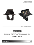
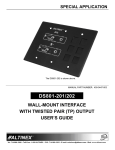
TNP500/502/Universal Tilt ‘N Plug®
Plug® Interconnect Box
User’s Guide
Welcome!
We greatly appreciate your purchase of the TNP500/502 Universal Tilt ‘N
Plug Interconnect Box. We are sure you will find it reliable and simple to
use. Superior performance for the right price, backed by solid technical and
customer support is what ALTINEX has to offer.
We are committed to providing our customers with Signal Management
Solutions® to the most demanding audiovisual installations at competitive
pricing and we welcome you to join the ranks of our many satisfied
customers throughout the world.
•
To turn off the main power, disconnect the power cord which powers
the socket on the pop-up panel. The power outlet socket should be
installed near to the equipment, and be easily accessible.
•
We recommend using wall outlets with a Ground Fault Circuit
Interrupter (GFCI) for maximum protection.
1.3 Cleaning
•
1. Precautions and Safety Warnings
1.4 FCC Notice
Please read this manual carefully before using your TNP500/502 and keep it
handy for future reference. These safety instructions are to ensure the long
life of your TNP500/502 and to prevent fire and shock hazards. Please read
them carefully and heed all warnings.
•
This device complies with Part 15 of the FCC Rules. Operation is
subject to the following two conditions: (1) This device may not cause
harmful interference, and (2) this device must accept any interference
received, including interference that may cause undesired operation.
•
This equipment has been tested and found to comply with the limits for
a Class A digital device, pursuant to Part 15 of the FCC Rules. These
limits are designed to provide reasonable protection against harmful
interference when the equipment is operated in a commercial
environment. This equipment generates, uses, and can radiate radio
frequency energy and, if not installed and used in accordance with the
instructions found herein, may cause harmful interference to radio
communications. Operation of this equipment in a residential area is
likely to cause harmful interference in which case the user will be
required to correct the interference at his own expense.
•
Any changes or modifications to the unit not expressly approved by
ALTINEX, Inc. could void the user’s authority to operate the
equipment.
1.1 General
•
There are no user serviceable parts inside. Qualified ALTINEX service
personnel must perform all service on the TNP.
1.2 Installation Precautions
•
To prevent fire or shock, do not expose this unit to water or moisture.
Do not place the TNP500/502 in direct sunlight, near heaters, or
heat-radiating appliances, or near any liquid. Exposure to direct
sunlight, smoke, or steam can harm internal components.
•
Handle the TNP carefully. Dropping or jarring can cause damage.
•
Do not force or pull any cable or power cord attached to the TNP.
•
Do not place heavy objects on top of the TNP500/502.
•
Do not use excessive force to push down on the top of the unit.
•
Never place fingers inside the opening on each side of the unit. This
action could cause injury due to sharp edges inside the unit.
Clean only with a dry cloth. Never use strong detergents or solvents
such as alcohol or thinner.
2. Installation Procedures
Step 1.
Cut an opening into the table’s surface. Refer to diagram on ALTINEX web site www.altinex.com for table cutout requirements.
Note: The tabletop must be 2.5 inches or less in thickness. Always confirm dimensions before cutting to insure specifications have not changed.
Step 2.
Insert the unit into the opening.
Step 3.
Place the 2 support brackets under the table and place them between the support mount
grooves on each side of the unit. Attach the brackets to the groove at the desired height
and secure them to the bottom of the table using the screws provided. See Diagram 4.
Step 4.
Attach the power cord to the table using the cable clamps provided. Keep a service loop
under the table to allow the unit to “pop up”. Exercise the unit several times while
adjusting the cable placement. Tighten the clamps when the unit “pops up” smoothly.
Step 5.
Connect the remaining cables under the table to their mating destinations using a service
loop as described above for the power cable.
Note: There are 2 RCA audio connectors on the front panel of the TNP502. The black
connector is known as audio left and the red is for audio right.
Step 6.
Tabletop
Support
Brackets (2)
Table
Securing
Screws (2)
To raise the TNP500/502 into position, push down on the top of the unit. To lower the unit, push down on the top of the unit until the latching
mechanism is engaged.
3. Limited Warranty/Return Policies
Please see the ALTINEX website at www.altinex.com for details on warranty and return policies.
400-0091-007
1
TNP500/502
User’s Guide
4. Technical Specifications
Specifications are subject to change. See www.altinex.com for up-to-date information.
Features/Description
TNP502
Mechanical
Pass-Through
AC Power
Maximum Table Thickness
10 ft (3 m)
Finish
TNP500/502
2.5 in (64 mm)
Flat Black
110 VAC
NEMA F-M (2 F to 1 M)
Height Above the Surface
3.5 in (88 mm)
Audio/video
6 ft (2 m)
Height Below the Surface
4.0 in (101 mm)
15-pin HD F-M (1)
Width
7.9 in (200 mm)
Network
RJ-45 F-M (1)
Depth
6.5 in (166 mm)
Modem
RJ-11 F-M (1)
TNP500
S-Video
4-pin Mini DIN F-M (1)
Weight
2.5 lb (1.1 kg)
Weight, Shipping (approx.)
3.8 lb (1.7 kg)
Computer Video
Composite Video
Control
Audio, Stereo
Audio Left Channel
Audio Right Channel
Yellow RCA F-F (1)
DB-9 F-M (1)
TNP502
3.5 mm F-M (1)
Weight
4.0 lb (1.8 kg)
Weight, Shipping (approx.)
5.6 lb (2.5 kg)
Red RCA F-F (1)
Black RCA F-F (1)
Compatibility
Tilt ‘N Plugs
TNP500
10°C-45°C
T° Maximum
60°C
Humidity
Accessories Included
Miscellaneous
T° Operating
90% non-condensing
Table 2. TNP500/502 Mechanical
Mounting hardware
Table 1. TNP502 General
Electrical
TNP502
Power
Power Rating
(pass-through power)
Table 3. TNP502 Electrical
400-0091-007
2
90-140 VAC,
5 A max.
TNP500/502
User’s Guide
5. About Your TNP500/502
The TNP500 is designed for installation into a table in a presentation or boardroom. The Tilt `N Plug Configurable Tabletop Interconnect Box provides access to
multimedia input connections when needed, and hides them when not needed. This unit can be configured with a wide variety of data or A/V connectors.
Using a tilting angular construction with pneumatic lift assist and mechanical latch, the TNP500 can be "tilted up" into a raised position for access to input plates,
or lowered flush into the table when not in use. Only light pressure is required to unlatch the top to open it, and slightly more pressure to push the lid down and
close the unit.
The TNP500 provides slots for 6 single-slot sectional plates on the exposed faceplate. Signals are passed through the unit to the underside of the table via cables
with mating connectors on the opposite end. For example, an RJ-45 F connector on the sectional plate would be terminated in an RJ-45 M connector at the
opposite end of a 6 ft (2 m) cable. Many sectional plate configurations are available and ordered separately. See our website for complete details.
The TNP502 is a "package" that covers the basic needs of many Tilt ‘N Plug users. This unit ships as a completely assembled product made up of one TNP500 and
one SP3500SC Sectional Plate. The input labels are already engraved and ready to go.
The SP3500SC includes the following connectors: 2 standard U.S. power receptacles, computer video (15-pin HD), COM Port/RS-232 (9-pin D), composite video
(RCA), S Video (4-pin mini DIN), audio (2-RCAs), computer audio (3.5 mm), modem (RJ-11), and network (RJ-45) input connectors. All signal connectors have 6
ft (2 m) cables attached that feed through to the bottom of the unit. The connectors and their labels may be customized for a fee.
TNP500
TNP502
COMPOSITE VIDEO
RCA F
AUDIO
RCA F (2)
Video
L. Audio
R. Audio
S. Video
Telephone
Network
!
110V ~ 60Hz 5A
AC POWER
110V,5A
4-PIN Mini DIN F
VIDEO
Computer
Audio
Control
15-PIN HD F
COMPUTER
RJ-45 F
NETWORK
RJ-11 F
TELEPHONE/MODEM
DB-9 F
CONTROL
3.5 mm F
STEREO AUDIO
400-0091-007
3
TNP500/502
User’s Guide
6. Application Diagrams
Diagram 1: Typical Setup
400-0091-007
4
TNP500/502
User’s Guide
Diagram 2: Dimensions
6.5"
[166 mm]
3.8"
[97 mm]
7.9"
[200 mm]
5.9"
[150 mm]
4.0"
[101 mm]
0.25" [6 mm]
5.9"
[150 mm]
400-0091-007
5
TNP500/502
User’s Guide
Diagram 3: Dimensions Open
Video
L. Audio
R. AUdio
S. Video
Telephone
Network
!
Computer
Audio
110V ~ 60Hz 5A
Control
7.5"
[191 mm]
4.0"
[102 mm]
3.5"
[88 mm]
7.5"
[189 mm]
400-0091-007
6
TNP500/502
User’s Guide
Diagram 4: Mounting
Tabletop
Support
Bracket
Support
Bracket
Table
Securing
Screw
Table
Securing
Screw
400-0091-007
7
TNP500/502
User’s Guide
Diagram 5: Popular Section Plates
1 SLOT PLATES
2 SLOT PLATES
3 SLOT PLATES
STANDARD PLATES
6 SLOTS
Many different plates can be installed on the TNP500 using up to 6 slots total. In addition to standard plates, custom plates can be made
using blank plates available. For a complete listing and detailed descriptions, see the ALTINEX web site at www.altinex.com.
400-0091-007
8
TNP500/502
User’s Guide
Diagram 6: TNP502 Configuration
Diagram 7: TNP502 Installed
400-0091-007
9
TNP500/502
User’s Guide
7. Operation
8. Troubleshooting Guide
7.1 Opening and Closing the TNP500/502
The TNP500/502 unit supplied was carefully tested and no problems were
detected. However, we would like to offer the following suggestions:
The TNP will open easily when the top is pressed down and then released.
8.1 Bad Signal
When the TNP is not in use, simply press the top down until it is level
with the surface of the table and then release. The unit will remain hidden
until needed again.
•
Make sure that no cable or power cord is damaged or pinched. If
there has been damage to the unit, do not use the TNP. Please contact
ALTINEX at (714) 990-2300 to have the unit repaired.
•
Please make sure that the highest quality video, audio, network, and
telephone cables or connectors are used.
•
If unit does not lift properly, please check the wear and tear on the
gas spring. If replacement of the gas spring is required, contact
ALTINEX at (714) 990-2300.
7.2 Power/Signal Connections
Connect external devices to the appropriate connector on the TNP.
Remember, the devices plugged into the AC power connectors should not
draw more than 5A AC.
400-0091-007
10