1
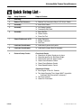
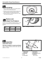
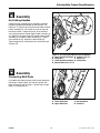
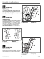
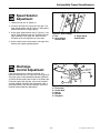
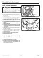
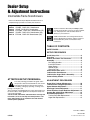
Dealer Setup
& Adjustment Instructions
Intermediate Frame Snowthrowers
Refer to the Dealer Setup & Adjustment binder Index for a
complete listing of products covered by this document.
Mfg. No. Description
7800084
7800085
7800086
7800087
7800138
I75246E, 7.5HP OHV, Snowthrower
I7524E, 7.5HP OHV, Snowthrower
EI75246E, 7.5HP OHV, Snowthrower (CE)
I7524EX, 7.5HP OHV, Snowthrower (CE)
EI75246, 7.5HP OHV Snowthrower (CE)
Sections and items denoted by the Setup symbol
provide the information necessary to fully assemble,
test, and prepare the units described above for
delivery to your customers.
Additional information concerning functional tests,
general adjustment procedures, and the location of
normal lubrication points are included in these
instructions.
TABLE OF CONTENTS:
SAFETY RULES........................................................2
SETUP PROCEDURES
Quick Setup List.......................................................3
Uncrating .................................................................4
Reduce and Check Tire Pressures .........................4
Assembly ..................................................................5
Un-Folding Handles ................................................5
Install Drift Cutters ..................................................5
Spout Rotator..........................................................6
Control Levers.........................................................6
Clean-Out Tool........................................................6
Check Fluid Levels & Fill.........................................7
Lubricate the Snowthrower.....................................7
Lubricate the Auger Shaft & Assembly..................8
Perform Safety Checks............................................9
ATTENTION SETUP PERSONNEL:
ADJUSTMENT PROCEDURES
The safety warnings provided in this guide and in
the operator's manual included with the unit contain
important information that must be obeyed when
assembling, setting-up, operating, servicing, transporting, or storing the unit.
These warnings are highlighted by the safety alert triangle symbol shown above, which signifies that an important safety message is being provided.
You must read, understand, and follow these warnings and
instructions, and use safe shop and work practices at all
times while working on or around this unit and all other
outdoor power equipment.
Auger Drive Linkage Adjustments .......................10
Traction Drive Linkage Adjustment......................10
Speed Selector Adjustment ..................................11
Discharge Control Adjustment .............................11
Chute Direction Control Rod Gear Adjustment...12
Scraper Bar & Skid Shoe Adjustment ..................12
Drive Belt Replacement .........................................13
Traction Drive Belt Replacement ..........................13
Auger Belt Replacement .......................................14
Form No. 7100731
Revision 00
6/2006
1
TP 300-5196-00-IS-SN
Intermediate Frame Snowthrowers
SAFETY RULES
Read these safety rules and follow them closely. Failure to obey these rules could result in loss of control
of unit, severe personal injury or death to you, or bystanders, or damage to property or equipment.
The triangle
in text signifies important cautions or warnings which must be followed.
GENERAL OPERATION
to protect themselves and others from injury.
• All operators should seek and obtain professional
and practical instruction.
• Always wear substantial footwear and appropriate
winter clothing. Wear foot-ware that improves traction on slippery slopes. DO NOT wear long scarves
or loose clothing that could become entangled in
moving parts.
• Before using, always visually check that all hardware
is present, in-tact, and secure. Replace worn or
damaged parts.
• Never operate the machine with defective guards, or
without safety protective devises in place.
• Stop engine before: refuelling, removing an attachment, making adjustments (unless the adjustment
can be made from the operator’s position).
• Follow the manufacturer’s recommendation for wheel
weights or counterweights.
• Adjust skid shoe height to clear gravel or crushed
rock surfaces.
• Do not touch snowthrower parts which may be hot
from operation. Allow such parts to cool before
attempting to service the unit.
CLEARING A CLOGGED DISCHARGE CHUTE
Hand contact with the rotating impeller inside the discharge chute is the most common cause of injury associated with snowthrowers. Always use a clean-out tool,
not your hands. to clean out the discharge chute.
To clear the chute:
1. SHUT OFF THE ENGINE.
2. Wait 10 seconds to be sure the impeller blades have
stopped rotating.
3. Always use a clean out tool, not your hands.
• Read, understand, and follow all instructions in the
manual and on the unit before starting.
• Only allow responsible adults, who are familiar with
the instructions, to operate the unit (local regulations
can restrict operator age).
• Clear the area of objects such as rocks, toys, wire,
etc., which could be picked up and thrown.
• Be sure the area is clear of other people. Stop unit if
anyone enters the area.
• Always look down and behind before and while travelling in reverse.
• Be aware of the discharge direction and do not point
it at anyone. Do not point the discharge at glass
enclosures, automobiles, or windows.
• Disengage all clutches (release drive and auger control levers) before starting the engine.
• Never leave a running unit unattended. Always disengage the auger and traction controls, stop engine,
and remove keys.
• Stop engine before unclogging chute.
• Operate only in daylight or good artificial light.
• Do not operate the unit while under the influence of
alcohol or drugs.
• Watch for traffic when operating near or crossing
roadways.
• Use extra care when loading or unloading the unit
into a trailer or truck.
• Keep in mind the operator is responsible for accidents occurring to other people or property.
• Data indicates that operators, age 60 years and
above, are involved in a large percentage of power
equipment-related injuries. These operators should
evaluate their ability to operate the unit safely enough
WARNING
Do Not
• Do not start or stop on a slope. If tires lose traction,
disengage the auger and proceed slowly straight
down the slope.
• Do not turn on slopes unless necessary, and then,
turn slowly and gradually downhill, if possible.
• Do not operate near drop-offs, ditches, or embankments. The unit could suddenly turn over if a wheel is
over the edge of a cliff or ditch, or if an edge caves in.
• Do not operate on wet surfaces. Reduced traction
could cause sliding.
• Do not shift to neutral and coast down hills.
Gasoline is highly flammable and must be
handled with care. Never fill the tank when the
engine is still hot from recent operation. Do not
allow open flame, smoking or matches in the
area. Avoid over-filling and wipe up any spills.
Do
• See your authorized dealer for recommendations
counterweights to improve stability.
• Travel up and down slopes, not across.
• Remove obstacles such as rocks, tree limbs, etc.
• Watch for holes, ruts, or bumps. Uneven terrain could
overturn the unit. Snow can hide obstacles.
• Use slow speed. Tires may lose traction on slopes.
Choose a low gear so that you will not have to stop or
shift while on the slope.
• Keep all movement on the slopes slow and gradual.
Do not make sudden changes in speed or direction.
• Always keep unit in gear especially when traveling
downhill.
TP 300-5196-00-IS-SN
EMISSIONS
• Engine exhaust from this product contains chemicals
known, in certain quantities, to cause cancer, birth defects,
or other reproductive harm.
• Look for the relevant Emissions Durability Period and Air
Index information on the engine emissions label.
2
6/2006
Intermediate Frame Snowthrowers
Quick Setup List Page
Setup Procedure
Steps to Perform
4
Uncrating
4
Reduce Tire Pressures
❏ Reduce Tire Pressure to 20 psi (137 kPa) & Check
4
Assembly
❏ Install Drift Cutters
5
Assembly
❏ Un-Folding Handles
❏ Connecting Shift Rods
6
Assembly
❏ Spout Rotator
❏ Control Levers
❏ Clean-Out Tool
7
Check Fluid Levels & Fill
❏ Auger Gearcase
❏ Engine Crankcase
❏ Fuel Tank
7
Lubricate Snowthrower
❏ Lubricate all grease & oil points
8
Lubricate Snowthrower
❏ Lubricate the auger Shaft & Assembly
9
Perform Safety Checks
Functional Checks
❏ Check that all Safety Guards are in place.
❏ Check Scraper Bars & Skid Shoe Height
❏ Check Drive Control & Auger Control
❏ Check Chute Direction Control
❏ Check Chute Deflector Control
❏ Check Speed Selector Control
Operational Checks
❏ Start Engine & Test ALL Controls
❏ Test Auger Stopping Time (Auger MUST stop within
5 seconds after the control is released.)
❏ Test Drive Controls
❏ Check For Fluid Leaks
6/2006
3
TP 300-5196-00-IS-SN
Intermediate Frame Snowthrowers
Uncrating
1. Using a reciprocating saw, cut crate sides from bottom skid. Lift crate from bottom skid.
2. Remove screws securing skid shoes to bottom skid.
Roll snowthrower from bottom skid backwards.
A
3. Make sure klik-pin is inserted through hole in wheel
and axle shaft and secured.
Figure 1. Klik-pin-locked
A. Klik-Pin
Reduce and
Check Tire Pressure
The tires are over inflated for shipping purposes. It is very
important to reduce the tire pressure to the following
pressure:
Size
PSI
bar
15 x 5.0-6
20
1,38
4.80-8
20
1,38
Figure 2. Checking Tire Pressure
B
Assembly
Install Drift Cutters
F
Drift cutters (if equipped) are mounted to snowthrower
auger housing backwards or shipped loose. Refer to
Figure 3. Remove hardware and install drift cutters with
hardware as shown.
G
H
Figure 3. Assemble Drift Cutters
A. Taptite Screw,
E Round Hole
5/16-18 x 3/4
F. Nut, 5/16-18
B. Drift Cutter
G. Lockwasher, 5/16-18
C. Tab
H. Capscrew,
D. Square Hole
5/16-18 x 3/4
TP 300-5196-00-IS-SN
4
6/2006
Intermediate Frame Snowthrowers
C
A
Assembly
G
D
Un-Folding Handles
Folding handles (if equipped) are shipped in the down
position and need to be rotated up and secured. Cut
cable ties (F, Figure 4) that secure control cables to lower
handle assembly (C). Be careful not to cut or damage
the control cables. Loosen wing nuts (B) and remove
any packing materials. Rotate upper handle assembly (A)
up. Slide 5/16-18 special bolts (D) through upper handle
assembly (A) and lower handle assembly (C). Tighten
5/16-18 locknuts (E) and 5/16-18 special bolts (D).
Tighten wingnuts (B), lockwashers (G) and 5/16-18 special bolts (D).
B
D
E
C
F
A
Figure 4. Un Folding Handle Bars (Some Models)
A. Upper Handle Assembly E. Locknut, 5/16-18
B. Wing Nuts
F. Cable Ties
C. Lower Handle Assembly G. Lockwasher
D. Special Bolts, 5/16-18 x 2
D
B
Assembly
C
Connecting Shift Rods
On models with folding handles the shift rods need to be
connected. Connect upper shift rod (B, Figure5) and
lower shift rod (A) rods as shown. Secure with carriage
bolts (C) and locknuts (D).
C
D
A
Figure 5. Connecting Shift Rods (Some Models)
A. Lower Shift Rod
C. Carriage Bolts
B. Upper Shift Rod
D. Locknuts
6/2006
5
TP 300-5196-00-IS-SN
Intermediate Frame Snowthrowers
Assembly
B
A
D
Spout Rotator
On models with folding handles the spout rotator is two
pieces and needs to be connected. Remove crank handle (A, Figure 7) from its packaging. Slide crank handle
(A) through dash (B) and slide into crank tube (C) line up
holes and secure with hair pin (D).
C
A
C
Assembly
Control Levers
On models with control lever cables need to be checked.
Remove wire ties or cardboard tubes (A, Figure 6) that
secure the control levers (B) to the handles (D). Make
sure that the “Z” bend ends (C) of the control cables (E)
are secured in the holes on the control levers (B) as
shown. Check that the cables (E) are not kinked and
have freedom of movement.
E
Figure 7. Control Levers (Folding Handle Models)
A. Crank Handles
C. Crank Tube
B. Dash
D. Hair Pin
E
C
C
B
B
A
D
A
D
C
Figure 6. Control Levers (Tube Handle Models)
A. Wire Ties
D. Handles
B. Control Levers
E. Control Cables
C. “Z” Bend Ends
A
Assembly
Clean-Out Tool
B
A clean-out tool is included with all models. Check to be
sure the clean-out tool is secured as shown in figure 8.
Figure 8. Clean-Out Tool (all Models)
A. Clean-Out Tool
C. Upper Clip
B. Lower Clip
TP 300-5196-00-IS-SN
6
6/2006
Intermediate Frame Snowthrowers
Check Fluid
Levels & Fill
1. Check auger gear case lubrication. Place the
snowthrower on a level surface. Remove the pipe
plug (A, Figure 9). The lubricant should be level with
the hole. If not, add Simplicity Winter Weight Worm
Gear Oil
2. Fill the engine crankcase with oil as described in the
engine Owner's Manual.
A
WARNING
Gasoline is highly flammable and must be
handled with care. Do not allow open flame,
smoking or matches in the area. Avoid overfilling.
Figure 9. Auger Gear Case Lubrication
A. Pipe Plug
3. Fill the fuel tank with gasoline. Be sure to check your
engine Owner's Manual for gasoline recommendations. Do not overfill; allow space for gasoline expansion.
Lubricate the
Snowthrower
CAUTION
It is very important that grease fittings on the
auger shaft are lubricated regularly. If the auger
rusts to shaft, damage to worm gear may occur if
shear pins do not break.
With an oil can, apply medium weight (10W) oil to points
shown in Figures 10 thru 15. There are two grease fittings in the auger shaft (Figure 15). Wipe fittings clean
and apply two or three shots of grease. Also, use grease
on points shown in Figure 12.
Figure 10. Lubricate Deflector Cap hinges
Generally, all moving metal parts should be oiled where
contact is made with other parts. Keep oil and grease off
belts and pulleys
NOTE: Make sure auger shaft grease fittings have been
lubricated to prevent shaft rusting. Apply grease until it
comes out both sides of shaft (gear box side and housing
bearing side). Grease may be squeezed out at shear pin
locations.
Figure 11. Lubricate Control Levers & Lube Axles
7
6/2006
TP 300-5196-00-IS-SN
Intermediate Frame Snowthrowers
A
Figure 15. Drive Lubrication
A. Hex Shaft
Figure 12. Lubricate Points Where chute Contacts
Flange (Oil); Lubricate Ring Gear and Pinion Gear
While Rotating Spout (Grease)
C
B
A
B
C
Figure 13. Lubricate Points Where Control Rods
Pass Thru Bracket
A
D
D
Figure 16. Lubricating the Auger Shaft Assembly
A. Grease Fittings
C. Cotter Pins
B. Shear Pins
D. Auger Assembly
Figure 14. Lubricate Free Hand Control
LUBRICATING THE AUGER SHAFT &
ASSEMBLY
1. Remove cotter pin (C, Figure 16) and shear pin (B).
2. Use a grease gun and squirt several shots of grease
into grease fitting (A).
3. Rotate auger assembly (D) several times to distribute
the grease evenly. Repeat step 2.
4. Reinstall shear pin (B) and cotter pin (C).
5. Repeat procedure for other side.
TP 300-5196-00-IS-SN
8
6/2006
Intermediate Frame Snowthrowers
Perform
Safety Checks
D
B
A
Check Engine Controls
C
1. Make sure all safety guards are in place and all nuts,
bolts, clips, cotter pins and wires are secure.
2. Check to make sure spark plug wire is attached.
3. Check all controls for proper operation:
a. The engine should stop when the key is removed.
b. The fuel shut-off valve should stop the flow of fuel
to the engine
E
c. The recoil starter or electric starter (if equipped)
should crank the engine when activated.
F
4. Check the engine area for oil or gasoline leaks.
Correct any problems in accordance with the engine
manufacturers instructions.
Figure 17. Check Engine Controls
A. Primer
D. Choke
B. Fuel Shut-Off Valve
E. Key
C. Recoil Starter
F. On/Off Switch
5. Check to make sure that the on/off switch is set to the
ON position.
A
Check Snowthrower Controls
C
1. Check the skid shoes to make sure they are set at the
desired height. Adjust if necessary.
B
D
2. Check the traction drive control (A, Figure 18).
Snowthrower motion should stop when the control is
released.
3. Check the auger control (C). Auger movement should
stop when the control is released.
4. Check the chute direction control (D) for proper
operation. The discharge chute should rotate freely in
both directions.
Figure 18. Snowthrower Controls
A. Traction Control
B. Speed Selector
C. Auger Control
D. Chute Direction Control
6. Check the speed selector (B) for smooth operation.
The control must move freely into each speed position gate and remain in position when released.
If controls do not function properly, perform the
appropriate adjustment as shown in the
Adjustment Section.
6. The auger is secured to the shaft by shear pins,
which will break if the auger strikes an object. Extra
shear pins are provided. Keep these pins with the
Operators Manual. Lubricate the auger shaft.
Operational Checks
1. Engage the auger control and release. Do this ten
(10) times. Auger should come to a complete stop
within five seconds each time. If not, perform
Auger Adjustments.
3. Engage traction control and release. Do this ten
times. Unit should come to a complete stop each
time. If it does not, perform the Traction Drive
Adjustments.
4. Remove the engine key. The engine must stop.
6/2006
9
TP 300-5196-00-IS-SN
Intermediate Frame Snowthrowers
Adjustments
A
Auger Drive Linkage
Adjustment
D
2. To adjust, loosen nut (D, Figure 19) by holding the
adjusting flats (A)and turning nut (D). Turn adjustment
flats and hold screw. The adjustment screw is a phillips
screw and the head can be held or turned by inserting a
screwdriver through the spring.
E
C
1. With the drive lever released, the hook (B, Figure 19)
should barely touch the lever (C) without raising it. There
can be a maximum 1/32” clearance as shown.
B
Figure 19. Auger Drive Adjustment
A. Adjusting Flats
D. Nut
B. Spring Hook
E. Adjustment Screw
C. Lever
3. Hold adjusting flats (A) and tighten nut (D).
4. Start unit and check auger. Auger must not be
engaged unless auger control is depressed.
5. With engine running, fully depress auger control, the
auger should engage and run normally.
6. Release auger control. Auger must stop within 5
seconds.
Traction Drive Linkage
Adjustment
D
2. To adjust tension on the cable loosen adjustment hex
nut (D) by holding the adjusting flats (A). Turn the
adjustment screw. The adjustment screw is a phillips
screw and the head can be held or turned by inserting a screwdriver through the traction drive clutch
cable spring
B
Figure 20. Traction Drive Adjustment
A. Adjusting Flats
D. Nut
B. Spring Hook
E. Adjustment Screw
C. Bellcrank Arm
WARNING
3. Engage the drive lever to check the adjustment.
When correct, tighten hex nut securely. The unit
should able to be pushed forward and back freely.
Do not over-tighten, as this may cause traction
drive to engage without depressing the traction
drive control (bellcrank arm must remain in down
position).
Run-In Adjustment
Verify that the cables are not over-tightened: With
speed selector in position 1 and traction drive
control fully released, push snowthrower forward.
The unit should move forward freely.
1. After 5 hours of use, check for proper adjustment.
Readjust clutch cable if necessary by increasing tension on cable. A small amount of bellcrank arm
movement is permissible if unit passes operating
checks described in the Caution at right.
TP 300-5196-00-IS-SN
E
C
1. With the drive lever released there should be no
slack in the cable when moved slightly from side to
side, but bellcrank arm (C, Figure 20) remains in fully
down position.
If unit does not move forward freely, the cable has
been over-tightened. To remedy, loosen tension
on clutch cable slightly, and recheck.
10
6/2006
Intermediate Frame Snowthrowers
Speed Selector
Adjustment
C
A
B
1. Loosen the two nuts (A, Figure 21).
A
2. Place the shift lever (B, Figure 18) in 5th gear. The
lower speed selector rod (B, Figure 21) will properly
locate itself due to an integral spring.
3. Grasp upper speed selector rod (C, Figure 21), and
pull up, then tighten the two nuts (A) while maintaining the position of the upper rod. Make sure the
shoulders of the carriage bolts are in the slots.
Figure 21. Drive Linkage
A. Nut
B. Lower Speed
Selector Rod
C. Upper Speed
Selector Rod
4. Always check traction drive tension and auger drive
tension after adjusting speed selector.
E
Discharge
Control Adjustment
A
If the discharge control is difficult to operate, first
lubricate the pinion gear (A, Figure 22) and ring gear (E).
The pinion gear can be adjusted by loosening the bolts
(C) which hold the pinion gear bracket. If the pinion gear
is too tight against the ring gear, move it away slightly
and then retighten the bolts. Check operation again. If
discharge control is still difficult to operate, see Chute
Direction Control Rod Gear Adjustment.
6/2006
D
B
C
Figure 22. Discharge Control
A. Pinion Gear
B. Control Rod
C. Bolt (2)
D. Bracket
E. Ring Gear
11
TP 300-5196-00-IS-SN
Intermediate Frame Snowthrowers
Chute Direction Control
Rod Gear Adjustment
If the discharge chute becomes difficult to rotate or
begins to operate erratically, the chute direction control
rod gears may require adjustment:
1. Loosen the gear bracket mounting nuts (Figure 23).
2. Slide the gear bracket into the position that provides
the best engagement between the gears.
Mounting Nuts
3. Tighten the bracket mounting nuts, and check for
smooth operation.
4. Readjust if necessary.
5. Lubricate the Chute Direction Control rod gears with
lithium grease.
Figure 23. Chute Direction Gear Adjustments
Scraper Bar &
Skid Shoe Adjustment
On smooth surfaces such as concrete or asphalt, the
scraper bar should scrape the surface. On surfaces such
as gravel, the scraper bar should be high enough so that
it will not pick up gravel or debris.
The height of the scraper bar is controlled by raising or
lowering the Skid Shoes (See Figure 24).
1. To raise the scraper bar height, rest the scraper bar on
a strip of wood equal in thickness to the desired height.
2. Make sure the scraper bar is parallel to the ground
surface.
3. Loosen the skid shoe nuts and let the skid shoes drop
to the surface.
4. Tighten the nuts, making sure the Skid Shoes are
adjusted equally and are parallel to the surface.
5. To lower the height of the scraper bar, raise the Skid
Shoes.
6. If the scraper bar becomes worn, it can be adjusted
by loosening the nuts and bolts attaching it to the
snowthrower, making the adjustment, and tightening
the hardware. It may also be replaced by removing
the mounting nuts and bolts attaching it to the
snowthrower.
A
C
B
Figure 24. Skid Shoe Adjustment
A. Scraper Bar
B. Skid Shoe
C. Nuts
B
The scraper bar is adjustable. (See Figure 25). If desired
scraper bar height adjustment cannot be achieved solely
by raising or lowering the skid shoes:
1. Loosen the nuts securing the scraper bar to the auger
housing, and raise or lower the scraper bar until
desired height is achieved.
2. Tighten the nuts, making sure the scraper bar is
parallel with the bottom edge of the auger housing.
TP 300-5196-00-IS-SN
A
Figure 25. Scraper Bar Adjustment
A. Scraper Bar
B. Nuts
12
6/2006
Intermediate Frame Snowthrowers
Drive Belt
Replacement
Traction Drive Belt & Pulley
Traction Drive Belt Replacement
WARNING
Snowthrower must move only when the traction
drive control is depressed, and must stop when
the lever is released (disengaged).
1. Disconnect the spark plug wire and fasten it away
from the spark plug. Remove belt cover.
2. Pull the drive belt idler pulley arm away from the belt
to relieve tension, and slide the belt off engine pulley
(A, Figure 27).
Figure 26. Traction Drive Pulley
(Lower Cover Removed For Clarity)
3. Slip the belt off the traction pulley (See Figure 26) and
pull the belt out of the unit between the auger pulley
and the traction pulley (the lower cover need not be
removed for this step).
A
4. Reverse the procedure to install the new belt. Be sure
there are no twists in the belt, and that the belt is
properly seated in the pulley grooves.
5. Replace the belt cover.
C
6. Start the unit, and check the traction drive for proper
operation. See "Traction Clutch Rod Adjustment" for
adjustment procedures.
B
D
E
Figure 27. Auger Drive Belt Pattern
A. Engine Pulley
D. Driven Pulley
B. Drive Belt
E. Belt Stops
C. Idler Pulley
6/2006
13
TP 300-5196-00-IS-SN
Intermediate Frame Snowthrowers
Auger Drive Belt Replacement
Belt Guide
Screws
WARNING
Auger must NOT rotate unless the Auger Control
lever has been depressed. Proper Auger Drive
Belt adjustments stop the auger within 5 seconds
after the Auger Control is disengaged.
Belt Guide
& Gap
1. Drain the fuel tank and run engine out of gas.
2. Disconnect spark plug wire and fasten it away from
the spark plug.
3. Remove belt cover.
Figure 28. Auger Belt Guide Adjustment
4. Loosen auger belt guide and slide belt off engine pulley and away from idler pulley. (See Figure 28).
Auger Drive Pulley
5. Depress and secure both the auger and traction control levers to provide clearance for belt removal.
6. Tilt the snowthrower forward and rest it on the auger
housing.
7. Remove lower cover.
8. Loosen hex screws securing the belt stop (Figure 29),
and pivot the belt stop away from the pulley to permit
removal of belt.
9. Pull the belt out of the unit, and install the new belt on
the auger drive pulley.
10. Position belt stop to provide 1/8" clearance between
stop and belt when engaged, and tighten securely.
Auger Belt Stop
Figure 29. Auger Drive Pulley and Belt Stop
11. Replace lower cover.
12. Return unit to normal upright operating position.
13. Remove both control levers.
14. Install auger belt over engine pulley.
15. Adjust auger belt guide as described under ADJUSTING AUGER BELT GUIDE.
16. Install belt cover.
17. Connect spark plug wire and fill fuel tank.
18. Start Unit and check auger for proper operation. See
DRIVE BELT ADJUSTMENT PROCEDURES if additional adjustment is necessary.
TP 300-5196-00-IS-SN
14
6/2006
Intermediate Frame Snowthrowers
NOTES
6/2006
15
TP 300-5196-00-IS-SN
Intermediate Frame Snowthrowers
NOTES
MANUFACTURING, INC.
500 N Spring Street / PO Box 997
Port Washington, WI 53074-0997 USA
© 2006 Simplicity Manufacturing, Inc. All Rights Reserved
16