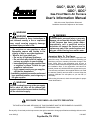
1
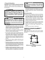
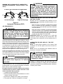
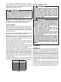
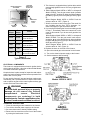
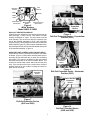
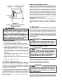
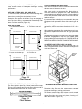
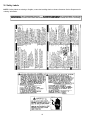
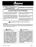
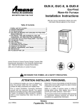
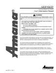
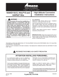
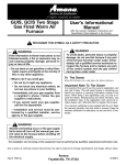
GUC*, GUX*, GUD*,
GDC*, GDC*
®
Gas-Fired Warm Air Furnace
™
User's Information Manual
Affix this manual, Specification Sheet and
Installation Instructions adjacent to the furnace.
WARNING
WARNING
WARNING
If the information in these instructions is
not followed exactly, a fire or explosion
may result causing property damage,
personal injury or loss of life.
– Do not store or use gasoline or other
flammable vapors and liquids in the
vicinity of this or any other appliance.
– What to do if you smell gas:
• Do not try to light any appliance.
• Do not touch any electrical switch; do
not use any phone in your building.
• Immediately call your gas supplier from
a neighbor’s phone. Follow the gas
supplier’s instructions.
• If you cannot reach your gas supplier,
call the fire department.
– Installation and service must be performed
by a qualified installer, service agency or
the gas supplier.
To avoid death, personal injury or property
damage, do not use this furnace if any part
of the furnace has been under water.
Immediately call a qualified service
technician to inspect the furnace and to
replace any part of the control system and
any gas control having been under water.
Important Note To The Owner
It is important that you fill out the owner’s registration card
and mail it today. This will assist Amana in contacting you
should any service or warranty information change in the
future. When filling in the registration card, be sure to
include the Model, Manufacturing and Serial Numbers, plus
the installation date. If the registration card cannot be
located, please call 1-800-843-0304 to register the furnace.
Your warranty certificate is also supplied with the unit. Read
the warranty carefully and note what is covered. Keep the
warranty certificate in a safe place, so you can find it, if
necessary.
Before using this manual, check the serial plate for proper
model identification.
WARNING
Should overheating occur or the gas supply
fail to shut off, turn off the manual gas
control valve to the furnace before shutting
off the electrical supply.
RECOGNIZE THIS SYMBOL AS A SAFETY PRECAUTION
THE INSTALLATION AND SERVICING OF THIS EQUIPMENT MUST BE PERFORMED BY QUALIFIED,
EXPERIENCED TECHNICIANS ONLY.
Due to policy of continual product improvement, the right is reserved to change specifications and design without notice.
June 1999 (2)
Amana
Fayetteville, TN 37334
10318817
Table of Contents
Important Note To The Owner ........................................................................................................................... 1
I. General Information ..................................................................................................................................... 3
II. Operation ...................................................................................................................................................... 5
III. Maintenance ................................................................................................................................................. 8
IV. Inspection of Furnace (Qualified Servicer Only) .................................................................................... 10
V. For More Information .................................................................................................................................. 11
VI. Safety Labels .............................................................................................................................................. 12
ATTENTION INSTALLING PERSONNEL
As a professional installer you have an obligation to
know the product better than the customer. This
includes all safety precautions and related items.
Remember, it is your responsibility to install the
product safely and to know it well enough to be able to
instruct a customer in its safe use.
Prior to actual installation, thoroughly familiarize
yourself with this manual. Pay special attention to all
safety warnings. Often during installation or repair it is
possible to place yourself in a position which is more
hazardous than when the unit is in operation.
Safety is a matter of common sense...a matter of
thinking before acting. Most dealers have a list of
specific good safety practices...follow them.
The precautions listed in this manual should not
supersede existing practices but should be considered
as supplemental information.
Remember to leave this manual with the homeowner.
2
WARNING
I. General Information
To avoid personal injury or fire, minimum
clearances to combustible surfaces must
be followed.
This furnace is built to provide many years of safe and
dependable service, providing it is properly installed and
maintained. However, abuse and/or improper use can
shorten the life of the furnace and create hazards for you,
the homeowner.
7. Make certain the required clearances for the furnace
are always maintained. These clearances are listed on
the furnace nameplate. If any question develops, contact the installer of the furnace, or another qualified
servicer.
WARNING
This product contains or produces a
chemical or chemicals which may cause
serious illness or death and which are
known to the State of California to cause
cancer, birth defects or other reproductive
harm.
UNIT INSTALLATION
Examine the furnace installation to determine the following:
1. The flue vent pipe is physically sound and sealed. The
vent slopes upward to vent terminal so condensate
drains back toward the furnace. The vent shows no
evidence of leaking or separation at joints or fittings.
2. The return air duct connection is physically sound,
sealed to the furnace casing, and terminates outside
the space containing the furnace.
3. The physical support of the furnace is sound without
sagging, cracks, or gaps around the base so as to
provide a seal between the support and the base.
4. There are no obvious signs of deterioration of the
furnace.
5. Check the burner flames for adjustment.
WARNING
To avoid possible equipment damage,
personal injury, fire or death, the following
instructions must be observed regarding
unit location, air requirements and operating
procedures.
UNIT LOCATION
1. The furnace area and the vicinity of any other gas
appliances must be kept clear and free of combustible
materials, gasoline, and other flammable vapors and
liquids. Also, do not store or use flammable items such
as paint, varnish, or lacquer in the area.
2. Do not store or use chlorine or fluorine products
(bleaches, cements, strippers, aerosols) near the unit.
They can corrode the heat exchanger.
3. Do not use the furnace closet as storage for brooms,
mops, brushes and oily rags or cloths. The area must
be kept clear, clean and free of lint. Furnace must be
kept free and clear of exposed or loose insulation
materials in the area of installation. Examine the furnace area when the furnace or additional insulation is
added since some insulation materials may be combustible.
4. Make sure the furnace is always connected to an
approved vent, in good condition, to carry combustion
products outdoors.
5. Familiarize yourself with the controls that shut off the
gas and electrical power to the furnace. If the furnace
is to be shut down at the end of the heating season, turn
off both the gas and electrical power. For safety, always
turn the gas and electrical power off before performing
service or maintenance on the furnace.
6. Establish a regular maintenance schedule to insure
efficient and safe operation of the furnace. The furnace
should be checked at the beginning of each heating
and cooling season by a qualified service technician.
MINIMUM UNIT CLEARANCES TO COMBUSTIBLE
SURFACES (UPFLOW AND COUNTERFLOW
INSTALLATIONS)
NOTE: GDC and GCD models require special subbase
when installed on combustible (wood only) floor (CFSB16,
20 or 24).
0"
A 1" Top Clearance
is also required
1"
1"
3"
Service Area
36"
Free Access
To Furnace
Figure 1
Upflow and Counterflow Clearances
(Top View)
3
WARNING
MINIMUM UNIT CLEARANCES TO COMBUSTIBLE
SURFACES (HORIZONTAL INSTALLATIONS - GDC
ONLY)
A SIX INCH TOP CLEARANCE IS ALSO REQUIRED.
0"
0"
6" 6"
12"
12"
Alcove
Left Air Discharge
It is vitally important that the furnace have
proper venting. GUC, GUX, GUD, GDC or
GCD model furnaces must never be
common vented with another gas fired
appliance. Any alteration to any venting
system must be in accordance with local
and national codes, and the manufacturer's
instructions.
COMBUSTION AIR (GUC, GUX, GUD, GDC AND GCD ONE PIPE SYSTEM)
Normally the air for combustion and ventilation can be
obtained from the surrounding unconfined space or louvered closet door.
• When a furnace is installed in a closet and the closet
door is louvered DO NOT OBSTRUCT LOUVERS.
Louvers must be open and clear to provide combustion
air to the furnace.
• When the furnace is installed in a confined space within
a home and the air for combustion and ventilation
enters the space through ducts from the outside...be
sure to check the entering and outlet (grilled) openings
so that they are always clear and clean.
Alcove
Right Air Discharge
Figure 2
Horizontal Clearances (GDC)
AIR REQUIREMENTS
WARNING
To avoid death, personal injury or property
damage, enough fresh air for proper
combustion and ventilation of flue gases
must be provided to this furnace. Most
homes require outside air to be supplied
into the furnace area.
IMPORTANT NOTE: Do not partition off a small area
around the furnace including a non louvered door. This
could obstruct the combustion air from reaching the furnace.
Improved construction and additional insulation in homes
have reduced the heat loss and made these homes much
tighter around doors and windows so that air infiltration is
minimal. This creates a problem to supply ventilation and/
or combustion air for gas fired or other fuel burning appliances. Any use of appliances that pull air out of the house
(clothes dryers, exhaust fans, fireplaces, etc.) increases
this problem and appliances could be starving for air.
COMBUSTION AIR (GUD AND GCD - TWO PIPE
SYSTEM)
NOTE: To insure proper operation of the furnace, both
combustion air and flue pipes must never become obstructed.
NOTE: The air for combustion and ventilation must not
come from a corrosive atmosphere.
If fuel-burning appliances are starved for air, the flue gases
which these appliances produce as they operate may not
vent outdoors properly, but remain in the home instead.
These flue gases may include carbon monoxide.
WARNING
To prevent possible death or personal injury
due to asphyxiation, Amana Condensing
Gas Fired Warm Air Furnaces must be
Category IV vented.
WARNING
Death or personal injury from asphyxiation
can result from exposure to carbon
monoxide.
Category IV venting must be gas and water tight. For
information on Category IV venting, refer to the installation
instructions available from the installing dealer, distributor,
or directly from Amana.
Carbon monoxide or “CO” is a colorless and odorless gas
produced when fuel is not burned completely or when the
flame does not receive sufficient oxygen.
Be aware of these air starvation signals which indicate
conditions that may result in carbon monoxide or that
carbon monoxide may be present:
1. Headaches-Nausea-Dizziness.
2. Excessive humidity-heavily frosted windows or a moist
“clammy” feeling in the home.
3. Smoke from a fireplace won’t draw up the chimney.
4. Flue gases won’t draw up the appliance vent pipe.
4
The vent system must slope toward the furnace for drainage of condensate. Provision must be made to drain the
condensate and protect the condensate drain trap and
drain line from freezing conditions.
PROPANE FURNACES ONLY
WARNING
To avoid death, personal injury or property
damage due to explosion or fire, install a
gas detecting warning device. Since the
odorant in propane gas can be reduced by
iron oxide (rust), a gas detecting warning
device is the only reliable method to detect
propane gas leaks.
WARNING
To prevent possible death or personal injury
due to asphyxiation, common venting with
other induced draft appliances is not
allowed. Carefully read and follow all
instructions given in this section.
WARNING
NOTE: The louvers in the furnace door and top must never
be obstructed. They must remain open so air can flow
through the furnace and cool internal components.
If the gas furnace is installed in a basement,
an excavated area or a confined space, it is
strongly recommended to contact a propane
supplier to install a gas detecting warning
device in case of a gas leak.
• Since propane gas is heavier than air,
any leaking gas can settle in any low
areas or confined spaces.
• Propane gas odorant may fade, making
the gas undetectable except with a
warning device.
An undetected gas leak will create a danger
of explosion or fire. If the presence of gas is
suspected, follow the instructions on the
cover of this manual. Failure to do so could
result in SERIOUS PERSONAL INJURY OR
DEATH.
INDOOR HUMIDITY
Relative humidity is the amount of water vapor in the air
relative to the amount the air can hold at the same temperature. Example: At 40% relative humidity, the air could hold
2 1/2 times as much moisture (2.5 x 40 = 100%) before
becoming saturated.
The colder the air; the less moisture it can hold. As air is
warmed, its ability to hold moisture is increased.
Example: A winter day, outdoor temperature 10°F, and
relative humidity of 70%. If that air enters a home and is
warmed to 72°F the relative humidity will drop to 6% (very
dry) if no more moisture is added.
Relative humidity is important to your health and home as
proper humidification helps reduce respiratory difficulties
and helps improve the indoor air quality.
A good relative humidity is one just high enough to barely
start condensation along the lower edges or lower corners
of the windows. More than that can be damaging.
II. Operation
THERMOSTAT
There are many types and styles of thermostats but the
operation is usually similar. BE SURE TO BECOME FAMILIAR WITH YOUR THERMOSTAT. The simplest type of
thermostat only starts and stops the furnace to maintain the
proper room temperature. The most widely used types will
control both heating and cooling functions and will have a
Fan Switch with Auto and ON settings. On Auto, the
circulating air blower will cycle on/off with the furnace but if
switched to ON it will run constantly whether or not the
furnace is on.
Frequent fogging or excessive condensation on inside
windows indicates the indoor humidity level is too high for
outdoor weather conditions. Damage to the building may
result if the condition persists. (Condensation on inside of
storm windows indicates loose inside windows. Adding
weather-stripping to tighten inside windows usually corrects this problem.)
The following table shows the recommended maximum
indoor humidity in relationship to the outdoor temperatures.
Temperature
(° F.)
+20°
+10°
0°
-10°
-20°
Humidity
In addition there are thermostats that automatically switch
from Heating to Cooling and with night setbacks. The night
set-back, or multiple set-back type, will lower the temperature at night or during the day when no one is at home.
35%
30%
25%
20%
15%
Table 1
5
Room Temperature
Thermostat
Cool/Heat
Temperature
Control Dial
5. This furnace is equipped with an ignition device which
automatically lights the burner. Do not try to light burner
by hand.
6. White Rodgers Model 36E36 or 36E37 or Honeywell
Model VR-8205: Turn the gas control knob clockwise
to the OFF position for either the White Rodgers
gas valve (Figure 4) or the Honeywell gas valve (Figure
5).
White Rodgers Model 36E22 or 36E23: Push the
selector switch to "OFF". (Figure 6)
7. Wait five minutes to clear out any gas. Then smell for
gas, including near the floor. This is important , because some types of gas are heavier than air.
8. If you smell gas following the five minute waiting period
in Step 7, immediately follow the instructions on the
cover of this manual. If you do not smell gas after five
minutes:
White Rodgers Model 36E36 or 36E37 or Honeywell
Model VR-8205: Turn the gas control knob counterclockwise
to the ON position for either the White
Rodgers 36E gas valve (Figure 4) or the Honeywell VR8205 gas valve (Figure 5).
White Rodgers Model 36E22 or 36E23: Push the
selector switch to "ON". (Figure 6)
9. Replace the door on the front of the furnace.
10. Open the manual gas valve external to the furnace.
11. Turn on the electrical power supply to the furnace.
12. Set thermostat to desired setting.
Thermostat
Control
Lever
Cool/Heat
Switch
Fan
Switch
System
Switch
OFF
Fan
Switch
AUTO
COOL
AUTO
COOL
ON
HEAT
AUTO
HEAT
ON
OFF
ON
Action
None
System only cools, fan
cycles off and on.
System only cools, fan
runs all the time.
System only heats, fan
cycles off and on.
System only heats, fan
runs all the time.
No heating or cooling,
fan runs all the time.
Figure 3
Typical Thermostat
ELECTRICAL COMPONENTS
This furnace is equipped with an electronic ignition device
which lights the burners. It also has a induced draft blower
to exhaust combustion products.
Keep both doors in place except for inspection and maintenance. An interlock switch prevents furnace operation if the
blower door is not in place.
Figure 4
White Rodgers
Models 36E36 or 36E37
Do not use this furnace if any part has been under water.
Immediately call a qualified servicer to inspect the furnace
and to replace any part of the control system and any gas
control which has been under water.
WARNING
To avoid death, personal injury or property
damage do not remove any internal
compartment
covers.
Electrical
components are contained in both
compartments. Contact a qualified servicer
at once if an abnormal condition is noticed.
OPERATING INSTRUCTIONS
1. Close the manual gas valve external to the furnace.
2. Turn off the electrical power supply to the furnace.
3. Set room thermostat to lowest possible setting.
4. Remove the louvered door on the front of the furnace
by turning the latch screw 1/4 turn.
Figure 5
Honeywell
Model VR-8205
6
WR
Redundant
Solenoid
O
F
F
INLET
M
1
P
3
C
2
Main
Solenoid
OUTLET
ON
ON/Off
Switch
Inlet Pressure Tap
(Side of Valve)
Main Regulator
Adjust
Outlet Pressure Tap
(Side of Valve)
Flame Roll-Out
Protection
Device
Figure 6
White Rodgers
Model 36E22 or 36E23
ROLL-OUT PROTECTION DEVICE
If flames from the burners are not properly drawn into the
heat exchanger, a flame roll-out limit switch will open
causing combustion to cease. This limit switch must be
reset manually. The roll-out limit switch is located on one
end of the manifold assembly for GUC, GUX and GDC
furnaces (Figure 7 and 8) and in the burner box on GUD and
GCD furnaces (Figure 10). GDC furnaces installed horizontally must have the roll-out limit switch located at the top end
of the manifold assembly. (Figure 9)
Figure 8
Roll-Out Protection Device - Counterflow
Position (GDC)
AUXILIARY LIMIT CONTROL (GDC AND GCD ONLY)
A second limit control is located on one side of the indoor
air blower. (Figure 11) Disconnect electrical power prior to
removing the non-louvered door to reach the secondary
limit control. The control is in addition to the main control
and shuts the furnace off in case of a blower failure. This
control is a manual reset control, which can be reset only
once. If the unit goes off on limit a second time, contact a
qualified servicer so the problem causing the control to
open can be corrected.
Flame Roll-Out
Protection
Device
Figure 9
Roll-Out Protection Device - Horizontal
Position (GDC)
Flame Roll-Out
Protection
Device
Flame Roll-Out
Protection
Device
Figure 7
Roll-Out Protection Device
(GUC and GUX)
Figure 10
Roll-Out Protection Device
(GUD and GCD)
7
Horizontal
Left Air Discharge
(GDC)
RESET AFTER CONTROL LOCK-OUT
If ignition has not been achieved for any reason after three
ignition cycles, the electronic control module will lock-out
the furnace. Ignition is no longer attempted. The control's
diagnostic light will then repeatedly flash once and then
pause. When this occurs, it may be necessary to reset the
control by turning the thermostat setting below room temperature for thirty seconds and then returning the setting to
the desired temperature. The control may also be reset
after a lock-out by turning off the electrical disconnect
switch to the furnace for thirty seconds. The control will
automatically reset after one hour.
Counterflow (GDC and GCD)
and Horizontal Right (GDC)
Air Discharge
Blower
Assembly
Transformer
Control
Board
IMPORTANT: If the furnace must be reset frequently to
obtain satisfactory operation, a problem exists with your
furnace that must be corrected. Contact a qualified servicer.
Figure 11
Auxiliary Limit Control Position
(GDC and GCD)
III. Maintenance
AT LEAST ONCE A YEAR, BEFORE THE HEATING
SEASON BEGINS, have the furnace checked by a qualified
servicer to be certain there is adequate combustion air and
that the furnace and the vent system are working properly.
WARNING
To avoid death, personal injury or property
damage due to fire or explosion, do not
reset the roll-out protection device. If it
opens, the cause must be investigated by a
qualified servicer before any attempt is
made to engage the roll-out protection
device and turn the furnace back on.
Have the vent pipe and combustion air pipe (some models)
checked for blockage by debris or leaks, which could permit
fumes to enter the house. Replace any damaged sections
of the vent pipe.
WARNING
TURNING OFF FURNACE
1. Set the thermostat to lowest setting.
2. Turn off the electrical power supply to the furnace.
3. Remove the louvered door on the front of the furnace
by turning the latch screws 1/4 turn each.
4. White Rodgers Model 36E36 or 36E37 or Honeywell
Model VR-8205: Turn the gas control knob clockwise
to the OFF position for either the White Rodgers
gas valves (Figure 4) or the Honeywell gas valve
(Figure 5).
White Rodgers Model 36E22 or 36E23: Push the
selector switch to "OFF". (Figure 6)
5. Close manual gas shut-off valve external to the furnace.
6. Replace the door on the furnace.
To avoid death or personal injury due to
electrical shock, disconnect the electrical
power before performing any maintenance.
REPLACING OR CLEANING FILTERS
WARNING
To avoid death, personal injury or property
damage, never operate furnace without a
filter installed. Dust and lint will build up on
internal parts resulting in loss of efficiency,
equipment damage and possible fire.
If filter replacement becomes necessary, it must be replaced with a filter of the same type and size that complies
with UL900 or CAN/ULC-S111 standards.
ELECTRONIC CONTROL MODULE
The furnace is equipped with a self-diagnostic electronic
control module. If a furnace component is not operating
properly, the control module will repeatedly flash a red light
on and off in a factory-programmed sequence, depending
on the problem encountered.
See the Specification Sheet for filter sizes.
WARNING
To avoid death or personal injury due to
electrical shock, disconnect the electrical
power before removing filters or performing
any maintenance.
If a furnace equipped with a self diagnostic module is not
operating properly, look through the observation window in
the blower access door and make note of the number of
flashes in the sequence. Contact a qualified servicer for
further information. Do not attempt to troubleshoot the
problem yourself.
The filter is designed for high velocity heating and cooling
applications. Filters must be inspected, cleaned or changed
every two months or as required. It is the owner's respon8
sibility to keep air filters clean. NOTE: Dirty filters are the
most common cause of inadequate heating or cooling
performance.
FILTER CLEANING AND REPLACING
Use a vacuum cleaner to clean out the blower area and the
adjacent area of the return air duct.
UPFLOW FILTERS (GUC, GUX, AND GUD)
To remove the filter contained in the furnace retaining rails,
disconnect electrical power to the furnace and remove the
lower door by turning the door latches 1/4 turn.
Wash, rinse, and dry a permanent filter. Both sides of a
metal filter should be sprayed with a dust adhesive as
recommended on the adhesive container. Spray adhesives
for use with permanent metal filters can be found at some
hardware stores.
Grasp the lower portion of the filter, lift up to disengage it
from the lower railing, move towards blower, drop filter
down. Pull filter outward. (Figure 12)
If permanent filters are badly torn or uncleanable, they must
be replaced with permanent filters of the same type and
size.
SIDE AIR RETURN
1. Lift filter above bottom
rail.
When replacing permanent filter used in side air return
applications, the filter must have dimensions of 16" x 25" x
1".
2. Tilt filter to clear rail.
When replacing permanent filter used in bottom air return
applications replace with same size and type permanent
filter.
Front of Furnace
Front of Furnace
Reinstall filter by placing it into the furnace along the side of
the blower. Engage filter in top rail, move toward side of
furnace and drop it into the bottom rail. BE SURE AIRFLOW
DIRECTION ARROW POINTS TOWARDS THE BLOWER.
Blower
Filter
Blower
COUNTERFLOW FILTERS (GDC AND GCD)
This manual discusses the furnace mounted filter rack
which is shipped with the furnace. Other filter arrangements
could have been used.
Grab Here
And Lift
3. Lower filter below top
rail.
4. Pull filter out.
Front of Furnace
Front of Furnace
Blower
Blower
Figure 12
Filter Removal
Figure 14
Counterflow Furnace Mounted Filter Rack
BOTTOM AIR RETURN (GUC, GUX, AND GUD)
The filter is held in place by a sheet metal retainer strap
(Figure 13). To change and clean the filter, slide one end of
the retainer toward the front and remove filter.
Remember dirty filters are the most common cause of
inadequate heating or cooling performance.
The furnace-mounted filter rack includes a rack mounted
on the top of the furnace. Two filters fit into the rack and rest
against the sides of the return air plenum, forming a “V”
above the furnace. (Figure 14)
Figure 13
Filter Retainer
9
The filters should be inspected and cleaned or changed
every two months or as required. In some installations, the
filters can be inspected and cleaned or changed after
disconnecting the electrical power and removing the optional access door in the return air plenum. If the installation
does not have an access door proceed as follows:
AIR CIRCULATING BLOWER MOTOR LUBRICATION
The air circulation blower motor bearings are permanently
lubricated. No further lubrication is required.
IV. Inspection of Furnace (Qualified
Servicer Only)
1. Disconnect the electrical power.
2. Remove the louvered door from the furnace by turning
the door latches 1/4 turn.
3. Remove the left filter first by reaching to the left side of
the blower, pushing the filter up slightly to remove it
from the filter rack. Then carefully pull the filter down
past the left side of the blower housing. Be careful not
to dislodge any trapped dirt or debris from the filter.
(Figure 14)
4. Remove the right filter by reaching to the left side of the
blower. Lift filter up slightly to remove it from the filter
rack. Move the filter to the left side of the return air
plenum, and down past the left side of the blower
housing. Be careful not to dislodge any trapped dirt or
debris from the filter. (Figure 14)
a. Some installations will have two throwaway filters. If
dirty, these filters must be thrown away and replaced with two new similar size throwaway filters.
b. Other installations will have two permanent filters.
Wash, rinse and dry dirty permanent filters. After
cleaning, both sides should be sprayed with a filter
adhesive (available in hardware stores) as instructed
on the adhesive container.
WARNING
To avoid death or personal injury due to
shock or burns, the following procedures
must be followed exactly, in sequence,
before inspecting this furnace.
1. Close gas shut-off valve.
2. Disconnect electrical power to furnace.
3. To allow the furnace to cool, wait 15
minutes before proceeding.
INSPECTION PROCEDURES
• Vacuum the burner vestibule annually.
• Burners, mounting brackets and all other parts in the
vestibule area for signs of deterioration.
• PVC flue pipe for leaks and holes (the PVC flue pipe
must slope upward away from the furnace).
• PVC flue outlet and air inlet (some models) for restriction (wasp nests, etc.) and general condition.
• Return air connection to the furnace for soundness,
proper sealing to the furnace casing and terminating
outside the space containing the furnace.
• Physical support of the furnace for proper seal between
the support and the base, without any sagging, cracks
or gaps, etc.
• Burner operation. After reconnecting electrical power
and gas to the furnace, set room thermostat to maximum setting to operate the furnace. Inspect the main
burner flames. Natural gas flames should be stable,
soft and blue. Propane gas flames may appear slightly
yellow. Dust may cause orange tips. Flame must extend directly outward from the burner without curling,
floating, or lifting off. On the GUD and GCD furnaces
only, the flames can be inspected through the sight
glass on the front cover. Only a qualified servicer
should ever remove the cover. (Figure 15)
When badly torn or uncleanable, permanent filters
must be replaced with permanent filters of the same
type and size.
5. To reinstall the filters, first MAKE CERTAIN THE
AIRFLOW DIRECTION ARROW POINTS TOWARDS
THE FURNACE. Then insert the filters from the left side
of the blower. Starting with the right filter, push the filter
into the plenum so that the bottom of the filter rests in
the filter rack and the upper edge rests against the side
of the plenum. Repeat with the left filter. (Figure 14)
6. Replace the blower door, then reconnect the electrical
power.
HORIZONTAL FILTERS (GDC)
For horizontally installed furnaces, filters must be installed
external to the furnace casing. A central return with filters
installed in the duct behind the return grille may be used.
Clean or replace filters every two months or sooner as
required (replace with the same size and type filter). Dirty
filters are the most common cause of inadequate heating or
cooling performance.
CONDENSATE COLLECTION AND DISPOSAL
(QUALIFIED SERVICER ONLY)
If the drain tubes or condensate collection standpipe assembly become blocked, the components may be removed, cleaned and reinstalled.
Check the burner flames for:
1. Good adjustment
2. Stable, soft and blue
3. Not curling, floating, or lifting off.
INDUCED DRAFT MOTOR LUBRICATION
The induced draft motor bearings are permanently lubricated. No further lubrication is required.
Figure 15
Burner Inspection
10
V. For More Information
Most questions can be answered by the local Amana dealer. Check with dealer first if needing any further information
regarding the operation, maintenance, or service of the furnace.
If you have any matters that are not resolved locally, or for more information on other heating and cooling products or
kitchen appliances offered by Amana is needed - please call:
CONSUMER INFORMATION LINE
AMANA TOLL FREE
1-800-843-0304 (U.S. only)
(Not a technical assistance line for dealers.)
________________________________________
Outside the U.S., call 1-319-622-5511.
(Not a technical assistance line for dealers.)
Your telephone company will bill you for the call.
Ask a participating Amana dealer about Amana's extended service plan. It adds to the strong warranty with
additional parts and labor coverage.
To obtain the proper labels, the Model, Manufacturing Number and Serial Number of the unit must be supplied.
These numbers are recorded on the nameplate of the furnace. For convenience, record this information here:
MODEL NUMBER: _ _ _ _ _ _ _ _ _ _
MANUFACTURING NUMBER: P _ _ _ _ _ _ _F
SERIAL NUMBER: _ _ _ _ _ _ _ _ _
11
VI. Safety Labels
NOTE: If safety labels are missing or illegible, contact the installing dealer or Amana Customer Service Department for
ordering information.
COMPARTMENT MUST BE
CE COMPARTIMENT DOIT RESTER
WARNING:THIS
CLOSED EXCEPT WHEN SERVICING AVERTISSEMENT:FERME, SAUF POUR L'ENTRETIEN
B13580-1 LA
12