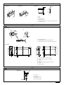
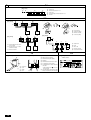
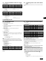
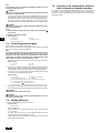
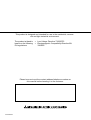
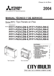
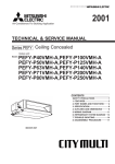
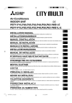
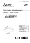
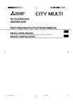
1
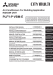
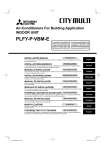
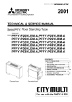
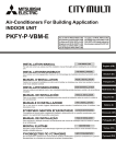
Air-Conditioners For Building Application INDOOR UNIT INSTALLATIONSHANDBUCH Zum sicheren und ordnungsgemäßen Gebrauch der Klimageräte das Installationshandbuch gründlich durchlesen. F INSTALLATION MANUAL For safe and correct use, please read this installation manual thoroughly before installing the air-conditioner unit. D GB PFFY-P-VLEM-E PFFY-P-VLRM-E MANUAL DE INSTALAÇÃO Para segurança e utilização correctas, leia atentamente este manual de instalação antes de instalar a unidade de ar condicionado. E°XEIPI¢IO O¢H°IøN E°KATA™TA™H™ °È· ·ÛÊ¿ÏÂÈ· Î·È ÛˆÛÙ‹ ¯Ú‹ÛË, ·Ú·Î·Ï›ÛÙ ‰È·‚¿ÛÂÙ ÚÔÛ¯ÙÈο ·˘Ùfi ÙÔ ÂÁ¯ÂÈÚ›‰ÈÔ ÂÁηٿÛÙ·Û˘ ÚÈÓ ·Ú¯›ÛÂÙ ÙËÓ ÂÁηٿÛÙ·ÛË Ù˘ ÌÔÓ¿‰·˜ ÎÏÈÌ·ÙÈÛÌÔ‡. РУКОВОДСТВО ПО УСТАНОВКЕ Для осторожного и правильного использования прибора необходимо тщательно ознакомиться с данным руководством по I NL P INSTALLATIEHANDLEIDING Voor een veilig en juist gebruik moet u deze installatiehandleiding grondig doorlezen voordat u de airconditioner installeert. GR MANUALE DI INSTALLAZIONE Per un uso sicuro e corretto, leggere attentamente questo manuale di installazione prima di installare il condizionatore d’aria. RU MANUAL DE INSTALACIÓN Para un uso seguro y correcto, lea detalladamente este manual de instalación antes de montar la unidad de aire acondicionado. E MANUEL D’INSTALLATION Veuillez lire le manuel d’installation en entier avant d’installer ce climatiseur pour éviter tout accident et vous assurer d’une utilisation correcte. CZ SV HG PO MONTAJ ELK‹TABI Emniyetli ve do¤ru biçimde nas›l kullan›laca¤›n› ö¤renmek için lütfen klima cihaz›n› monte etmeden önce bu elkitab›n› dikkatle okuyunuz. TR установке до выполнения установки кондиционера. 3 3.1 [Fig. 3.1.1] C D For PFFY-P-VLEM-A Model name 20 · 25 32 · 40 50 · 63 B 630 B A (B) (A) (mm) (B) (A) (B) 1050 1170 1410 More than 50 More than 50 More than 50 A Floor B Wall C Ceiling D Secure large enough space to prevent that blowout air is blocked. [Fig. 3.1.2] <Upward blowing type> <Forward blowing type> B For PFFY-P-VLRM-A 20 50 B 639 611 Model name 20 · 25 32 · 40 50 · 63 A (D) (C) C (C) 660 780 1030 More than 240 More than 240 More than 240 A Floor B Ceiling D C Piping space D Electrical part service space (D) C (D) (D) A (D) (mm) (C) D 4 4.1 [Fig. 4.1.2] [Fig. 4.1.7] [Fig. 4.1.6] For fixing on the floor For fixing on the wall <Viewed from bottom of the unit> <Viewed from front of the unit> A (F) 300 114 A 205 [Fig. 4.1.3] [Fig. 4.1.4] (F) [Fig. 4.1.5] B C 170 (E) 205 (E) E D C F Model name 20 · 25 32 · 40 50 · 63 A Front panel B Control panel cover C Side casing D Floor hole for fixing E Level adjusting screws (supplied) F Screw plate (supplied) (E) (F) 1050 1170 1410 640 760 1000 4.2 [Fig. 4.2.1] PFFY-VLEM-E PFFY-VLRM-E L Z Z L A A 2 X W A X W Floor hole for fixing 630 220 [Fig. 4.1.1] 4.3 [Fig. 4.3.1] [Fig. 4.3.2] [Fig. 4.3.3] B A C 1 C 4 2 E 2 D 3 8 5 9 A Duct B Tape C Blowout hole section D Insulating material E Insulating material (10 mm in thickness. Be provided around the blowout hole section.) A Flare cutting dimensions B Refrigerant pipe sizes & Flare nut tightening torque C Apply refrigerating machine oil over the entire flare seat surface. 5.1 [Fig. 5.1.1] A B C B [Fig. 5.1.2] G 80 80 G A B 50 50 A B 35 100 35 C D 430 C D 430 100 E E 90 45 90 F 45 6 F A Refrigerant pipe flare connection (for gas): LP B Refrigerant pipe flare connection (for liquid): HP C Drain pan D Stainer E Hose (accessory) (External diameter ø27 (end ø20)) F Air filter G Electrical part box 6.2 [Fig. 6.2.1] A B C D E A Indoor unit B Strainer (accessory) C Drain pan D Hose band (accessory) E Drain hose (accessory) 3 7 7.1 [Fig. 7.1.1] A D B C C E C C C C C A Switch 16 A B Overcurrent protection 16 A C Indoor unit D Total operating current be less than 16 A E Pull box 7.2 [Fig. 7.2.1] A B M1M2 M1M2 S TB3 [Fig. 7.2.3] A 1 2 TB5 M1M2 S [Fig. 7.2.4] 1 2 TB15 TB5 TB15 2 N L A B DC24~30V C C N A M1 DC10~13V A 1 L M2 D 1 C B 2 1 2 (A, B) C A Non-polarized B Upper level (TB15) C Remote Controller D Lower level (TB5) G Outdoor unit H Earth I Indoor unit J Remote controller K Non-polarized 2-wire [Fig. 7.2.5] A B M1M2 A M1M2 S TB3 TB5 G M1M2 S *1 H TB5 I A B C I I L1 Terminal block for indoor transmission cable L2 J I K Terminal block for outdoor transmission cable Remote controller C C F L3 J I *2 L4 R J J 7.3 7.4 D B C 1 4 DC 24 to 30 V B Network remote controller C Terminal bed for power supply D Shielding E Terminal bed for transmission cable F A 1 A Control box B Cover C Screw D Hook 2 L G N C E H <Address board> SW1 ON W254613G03 To single-phase power supply To terminal bed for outdoor transmission cable * Take shielding earth door unit side. F H [Fig. 7.4.1] A on the out- To terminal bed for transmission cable, remote controller, indoor BC controller FP-AD-R 3 2 1 SWA MADE IN JAPAN SWC 8 10 1 JP1 240V 220V [Fig. 7.3.2] [Fig. 7.3.1] SW5 SW14 N0 N0 CN82 SW12 SW11 0 0 0 10 1 1 6 JP2 JP3 JP4 [Fig. 7.2.2] CN62 1 Contents 1. Safety precautions ...................................................................................... 5 1.1. Before installation and electric work .......................................... 5 1.2. Precautions for devices that use R410A or R407C refrigerant ... 5 1.3. Before getting installed .............................................................. 6 1.4. Before getting installed (moved) - electrical work ...................... 6 1.5. Before starting the test run ........................................................ 6 2. Indoor unit accessories ............................................................................... 6 3. Selecting an installation site ....................................................................... 6 3.1. Securing installation and service space .................................... 7 3.2. Combining indoor units with outdoor units ................................ 7 4. Installing the unit ......................................................................................... 7 4.1. Assembling the unit ................................................................... 7 4.2. Center of gravity and product weight ......................................... 7 4.3. Blowout changing procedure ..................................................... 7 5. Refrigerant pipe and drain pipe specifications ............................................ 8 5.1. Refrigerant pipe and drain pipe size .......................................... 8 6. Connecting refrigerant pipes and drain pipes ............................................. 8 6.1. Refrigerant piping work ............................................................. 8 6.2. Drain piping work ....................................................................... 8 7. Electrical wiring ........................................................................................... 9 7.1. Power supply wiring ................................................................... 9 7.2. Connecting remote controller, indoor and outdoor transmission cables ........................................................................................ 9 7.3. Connecting electrical wires ..................................................... 10 7.4. Setting addresses .................................................................... 10 7.5. Sensing room temperature with the built-in sensor in a remote controller .................................................................................. 10 Symbols used in the illustrations : Indicates an action that must be avoided. : Indicates that important instructions must be followed. • : Indicates a part which must be grounded. : Indicates that caution should be taken with rotating parts. (This symbol is displayed on the main unit label.) <Color: yellow> • : Beware of electric shock (This symbol is displayed on the main unit label.) <Color: yellow> Warning: • Carefully read the labels affixed to the main unit. Warning: • • • • • • • • • • Ask the dealer or an authorized technician to install the air conditioner. - Improper installation by the user may result in water leakage, electric shock, or fire. Install the air unit at a place that can withstand its weight. - Inadequate strength may cause the unit to fall down, resulting in injuries. Use the specified cables for wiring. Make the connections securely so that the outside force of the cable is not applied to the terminals. - Inadequate connection and fastening may generate heat and cause a fire. Prepare for typhoons and other strong winds and earthquakes and install the unit at the specified place. - Improper installation may cause the unit to topple and result in injury. Always use an air cleaner, humidifier, electric heater, and other accessories specified by Mitsubishi Electric. - Ask an authorized technician to install the accessories. Improper installation by the user may result in water leakage, electric shock, or fire. Never repair the unit. If the air conditioner must be repaired, consult the dealer. - If the unit is repaired improperly, water leakage, electric shock, or fire may result. Do not touch the heat exchanger fins. - Improper handling may result in injury. When handling this product, always wear protective equipment. EG: Gloves, full arm protection namely boiler suit, and safety glasses. - Improper handling may result in injury. If refrigerant gas leaks during installation work, ventilate the room. - If the refrigerant gas comes into contact with a flame, poisonous gases will be released. Install the air conditioner according to this Installation Manual. - If the unit is installed improperly, water leakage, electric shock, or fire may result. • • 1.2. Precautions for devices that use R410A or R407C refrigerant Caution: • • • • • Do not use the existing refrigerant piping. - The old refrigerant and refrigerator oil in the existing piping contains a large amount of chlorine which may cause the refrigerator oil of the new unit to deteriorate. Use refrigerant piping made of C1220 (Cu-DHP) phosphorus deoxidized copper as specified in the JIS H3300 “Copper and copper alloy seamless pipes and tubes”. In addition, be sure that the inner and outer surfaces of the pipes are clean and free of hazardous sulphur, oxides, dust/dirt, shaving particles, oils, moisture, or any other contaminant. - Contaminants on the inside of the refrigerant piping may cause the refrigerant residual oil to deteriorate. Store the piping to be used during installation indoors and keep both ends of the piping sealed until just before brazing. (Store elbows and other joints in a plastic bag.) - If dust, dirt, or water enters the refrigerant cycle, deterioration of the oil and compressor trouble may result. Use ester oil, ether oil or alkylbenzene (small amount) as the refrigerator oil to coat flares and flange connections. - The refrigerator oil will degrade if it is mixed with a large amount of mineral oil. Use liquid refrigerant to fill the system. - If gas refrigerant is used to seal the system, the composition of the refrigerant in the cylinder will change and performance may drop. 5 D F E • I Caution: Describes precautions that should be observed to prevent damage to the unit. NL Describes precautions that should be observed to prevent danger of injury or death to the user. P • GR Warning: RU • Symbols used in the text TR • CZ s The “Safety precautions” provide very important points regarding safety. Make sure you follow them. SV s Before installing the unit, make sure you read all the “Safety precautions”. Have all electric work done by a licensed electrician according to “Electric Facility Engineering Standard” and “Interior Wire Regulations”and the instructions given in this manual and always use a special circuit. - If the power source capacity is inadequate or electric work is performed improperly, electric shock and fire may result. Keep the electric parts away from water (washing water etc.). - It might result in electric shock, catching fire or smoke. Securely install the outdoor unit terminal cover (panel). - If the terminal cover (panel) is not installed properly, dust or water may enter the outdoor unit and fire or electric shock may result. When installing and moving the air conditioner to another site, do not charge the it with a refrigerant different from the refrigerant specified on the unit. - If a different refrigerant or air is mixed with the original refrigerant, the refrigerant cycle may malfunction and the unit may be damaged. If the air conditioner is installed in a small room, measures must be taken to prevent the refrigerant concentration from exceeding the safety limit even if the refrigerant should leak. - Consult the dealer regarding the appropriate measures to prevent the safety limit from being exceeded. Should the refrigerant leak and cause the safety limit to be exceeded, hazards due to lack of oxygen in the room could result. When moving and reinstalling the air conditioner, consult the dealer or an authorized technician. - If the air conditioner is installed improperly, water leakage, electric shock, or fire may result. After completing installation work, make sure that refrigerant gas is not leaking. - If the refrigerant gas leaks and is exposed to a fan heater, stove, oven, or other heat source, it may generate noxious gases. Do not reconstruct or change the settings of the protection devices. - If the pressure switch, thermal switch, or other protection device is shorted and operated forcibly, or parts other than those specified by Mitsubishi Electric are used, fire or explosion may result. To dispose of this product, consult your dealer. Do not use a leak detection additive. HG • PO 1.1. Before installation and electric work GB 1. Safety precautions • • • • • Do not use a refrigerant other than R410A or R407C. - If another refrigerant (R22, etc.) is used, the chlorine in the refrigerant may cause the refrigerator oil to deteriorate. Use a vacuum pump with a reverse flow check valve. - The vacuum pump oil may flow back into the refrigerant cycle and cause the refrigerator oil to deteriorate. Do not use the following tools that are used with conventional refrigerants. (Gauge manifold, charge hose, gas leak detector, reverse flow check valve, refrigerant charge base, vacuum gauge, refrigerant recovery equipment) - If the conventional refrigerant and refrigerator oil are mixed in the R410A or R407C, the refrigerant may deteriorated. - If water is mixed in the R410A or R407C, the refrigerator oil may deteriorate. - Since R410A or R407C does not contain any chlorine, gas leak detectors for conventional refrigerants will not react to it. Do not use a charging cylinder. - Using a charging cylinder may cause the refrigerant to deteriorate. Be especially careful when managing the tools. - If dust, dirt, or water gets in the refrigerant cycle, the refrigerant may deteriorate. • • • • • • • • GB 1.3. Before getting installed Caution: • D • • E F • I • P NL • Do not install the unit where combustible gas may leak. - If the gas leaks and accumulates around the unit, an explosion may result. Do not use the air conditioner where food, pets, plants, precision instruments, or artwork are kept. - The quality of the food, etc. may deteriorate. Do not use the air conditioner in special environments. - Oil, steam, sulfuric smoke, etc. can significantly reduce the performance of the air conditioner or damage its parts. When installing the unit in a hospital, communication station, or similar place, provide sufficient protection against noise. - The inverter equipment, private power generator, high-frequency medical equipment, or radio communication equipment may cause the air conditioner to operate erroneously, or fail to operate. On the other hand, the air conditioner may affect such equipment by creating noise that disturbs medical treatment or image broadcasting. Do not install the unit on a structure that may cause leakage. - When the room humidity exceeds 80 % or when the drain pipe is clogged, condensation may drip from the indoor unit. Perform collective drainage work together with the outdoor unit, as required. The indoor models should be installed the ceiling over than 2.5 m from floor. 1.5. Before starting the test run Caution: • • • 1.4. Before getting installed (moved) - electrical work • Caution: GR • Ground the unit. - Do not connect the ground wire to gas or water pipes, lightning rods, or telephone ground lines. Improper grounding may result in electric shock. • Turn on the power at least 12 hours before starting operation. - Starting operation immediately after turning on the main power switch can result in severe damage to internal parts. Keep the power switch turned on during the operational season. Do not touch the switches with wet fingers. - Touching a switch with wet fingers can cause electric shock. Do not touch the refrigerant pipes during and immediately after operation. - During and immediately after operation, the refrigerant pipes are may be hot and may be cold, depending on the condition of the refrigerant flowing through the refrigerant piping, compressor, and other refrigerant cycle parts. Your hands may suffer burns or frostbite if you touch the refrigerant pipes. Do not operate the air conditioner with the panels and guards removed. - Rotating, hot, or high-voltage parts can cause injuries. Do not turn off the power immediately after stopping operation. - Always wait at least five minutes before turning off the power. Otherwise, water leakage and trouble may occur. 2. Indoor unit accessories The unit is provided with the following accessories: Part No. 1 2 3 4 5 TR RU • Install the power cable so that tension is not applied to the cable. - Tension may cause the cable to break and generate heat and cause a fire. Install an leak circuit breaker, as required. - If an leak circuit breaker is not installed, electric shock may result. Use power line cables of sufficient current carrying capacity and rating. - Cables that are too small may leak, generate heat, and cause a fire. Use only a circuit breaker and fuse of the specified capacity. - A fuse or circuit breaker of a larger capacity or a steel or copper wire may result in a general unit failure or fire. Do not wash the air conditioner units. - Washing them may cause an electric shock. Be careful that the installation base is not damaged by long use. - If the damage is left uncorrected, the unit may fall and cause personal injury or property damage. Install the drain piping according to this Installation Manual to ensure proper drainage. Wrap thermal insulation around the pipes to prevent condensation. - Improper drain piping may cause water leakage and damage to furniture and other possessions. Be very careful about product transportation. - Only one person should not carry the product if it weighs more than 20 kg. - Some products use PP bands for packaging. Do not use any PP bands for a means of transportation. It is dangerous. - Do not touch the heat exchanger fins. Doing so may cut your fingers. - When transporting the outdoor unit, suspend it at the specified positions on the unit base. Also support the outdoor unit at four points so that it cannot slip sideways. Safely dispose of the packing materials. - Packing materials, such as nails and other metal or wooden parts, may cause stabs or other injuries. - Tear apart and throw away plastic packaging bags so that children will not play with them. If children play with a plastic bag which was not torn apart, they face the risk of suffocation. Accessories Screw plate Level adjusting screw Strainer Drain hose Hose band Qty 4 4 1 1 1 Place to set Set inside the packaging material PO HG SV CZ 3. Selecting an installation site • Select a location so that air can be blown into all corners of the room. • Avoid locations exposed to outside air. • Select a location free of obstructions to the airflow in and out of the unit. • Avoid locations exposed to steam or oil vapour. • Avoid locations where combustible gas may leak, settle or be generated. • Avoid installation near machines emitting high-frequency waves (high-frequency welders, etc.). • Avoid locations where the airflow is directed at a fire alarm sensor. (Hot air could trigger the alarm during the heating operation.) • Avoid places where acidic solutions are frequently handled. • Avoid places where sulphur-based or other sprays are frequently used. 6 • If the unit is run for long hours at high temperature/high humidity (due point above 23 °C), due condensation may be produced in the indoor unit. When operating the units in this condition, add insulation material (10-20 mm) to the entire surface of the indoor unit to avoid due condensation. Warning: Ensure that the unit is installed in a place strong enough to sustain its weight. If there is a lack of strength, it may cause the unit to fall down, resulting in an injury. 3.1. Securing installation and service space For PFFY-P-VLEM-E Model name 20 · 25 32 · 40 50 · 63 (mm) (A) 1050 1170 1410 3.2. Combining indoor units with outdoor units For combining indoor units with outdoor units, refer to the outdoor unit installation manual. (B) More than 50 More than 50 More than 50 [Fig. 3.1.1] (P.2) A Floor C Ceiling B D Secure large enough space to prevent that blowout air is blocked. Wall For PFFY-P-VLRM-E Model name 20 · 25 32 · 40 50 · 63 (mm) (C) 660 780 1030 (D) More than 240 More than 240 More than 240 [Fig. 3.1.2] (P.2) <Upward blowing type> A Floor B Ceiling C Piping space D Electrical part service space GB <Forward blowing type> D 4. Installing the unit 4.1. Assembling the unit 4.2. Center of gravity and product weight [Fig. 4.1.2] (P.2) 3 Open the control panel cover, loosen the upper securing screw. [Fig. 4.1.3] (P.2) Product Weight (kg) 23 23 25 26 30 32 E Z 335 335 335 335 335 335 For PFFY-P-VLRM-E 5 Install the unit frame in parallel with the floor securely when installing. If the floor is not flat, be sure to use the supplied level adjusting screws to maintain the unit body at level. [Fig. 4.1.5] (P.2) D Floor hole for fixing E Level adjusting screws (supplied) F Screw plate (supplied) Model name W L X Z Product Weight (kg) PFFY-P20VLRM-E PFFY-P25VLRM-E PFFY-P32VLRM-E PFFY-P40VLRM-E PFFY-P50VLRM-E PFFY-P63VLRM-E 640 640 760 760 1000 1000 100 100 100 100 100 100 17 17 17 17 17 17 335 335 335 335 335 335 18.5 18.5 20 21 25 27 P [Fig. 4.1.4] (P.2) GR 4 Pull up the side casing. 4.3. Blowout changing procedure There are the following two methods of fixing the unit for purposes of preventing the unit from falling down. Where fixing is necessary, screw the unit at the specified position given below. For fixing on the floor [Fig. 4.1.6] (P.2) (For PFFY-P-VLRM Series only) To change the blowout from upward to forward in the case of the flush type units PFFY-P-VLRM Series, follow the procedure below. 6 Remove the screws, lift to remove the blowout hole in direction 1, turn the blowout hole 180° 2, and set the hole forward 3. TR Note: There are two level adjusting screws on both sides each, a total of four. [Fig. 4.3.1] (P.3) 7 Set the blowout hole just as it was removed, and tighten the screws. <Viewed from bottom of the unit> [Fig. 4.3.2] (P.3) For fixing on the wall [Fig. 4.1.7] (P.2) <Viewed from front of the unit> Model name 20 · 25 32 · 40 50 · 63 X 17 17 17 17 17 17 (E) 1050 1170 1410 (F) 640 760 1000 Note: When fixing on the wall, fix the unit with the electrical parts removed from the side. Notes: • When handling the blowout hole, be careful that the insulating material lined inside is not peeled off. • Be careful not to get your hand injured by sheet metal edges. • When connecting a duct to the blowout hole, be sure to insert the duct to the hilt of the blowout hole, and provide insulating material over the duct. Also, seal the joints between the duct and unit body with aluminum tape. 8) (8 • If you want to use the unit without connecting a duct to the blowout hole, be sure to provide soft urethane form around the blowout hole in order to 9) prevent the blowout hole section from dew condensation. (9 CZ Side casing L 100 100 100 100 100 100 SV Control panel cover C W 640 640 760 760 1000 1000 [Fig. 4.3.3] (P.3) A Duct B Tape C Blowout hole section D Insulating material E Insulating material (10 mm in thickness. Be provided around the blowout hole section.) HG B PFFY-P20VLEM-E PFFY-P25VLEM-E PFFY-P32VLEM-E PFFY-P40VLEM-E PFFY-P50VLEM-E PFFY-P63VLEM-E I Front panel 2 Hold the bottom of the front panel with your hands, and gently lift it. The front panel should fall down forward. 7 PO A Floor hole for fixing For PFFY-P-VLEM-E Model name NL A [Fig. 4.1.1] (P.2) F [Fig. 4.2.1] (P.2) 1 Loosen two screws fixing the front panel. RU How to disassemble the unit 5. Refrigerant pipe and drain pipe specifications 1 Select the thickness of insulating material by pipe size. To avoid dew drops, provide sufficient antisweating and insulating work to the refrigerant and drain pipes. When using commercially available refrigerant pipes, be sure to wind commercially available insulating material (with a heat-resisting temperature of more than 100°C and thickness given below) onto both liquid and gas pipes. Be also sure to wind commercially available insulating material (with a form polyethylene’s specific gravity of 0.03 and thickness given below) onto all pipes which pass through rooms. Pipe size 6.4 mm to 25.4 mm 28.6 mm to 38.1 mm Insulating material’s thickness More than 10 mm More than 15 mm 2 If the unit is used on the highest story of a building and under conditions of high temperature and humidity, it is necessary to use pipe size and insulating material’s thickness more than those given in the table above. 3 If there are customer’s specifications, simply follow them. 5.1. Refrigerant pipe and drain pipe size [Fig. 5.1.1] (P.3) A Flare cutting dimensions B Refrigerant pipe sizes & Flare nut tightening torque C Apply refrigerating machine oil over the entire flare seat surface GB A Flare cutting dimensions D Copper pipe O.D. (mm) ø6.35 ø9.52 ø12.7 ø15.88 Flare dimensions øA dimensions (mm) 8.7 – 9.1 12.8 – 13.2 16.2 – 16.6 19.3 – 19.7 B Refrigerant pipe sizes & Flare nut tightening torque R410A F E P20/25/32/40 P50 P63 I * Gas pipe Liquid pipe Pipe size Tightening torque (N·m) Pipe size Tightening torque (N·m) Pipe size Tightening torque (N·m) Pipe size Tightening torque (N·m) Liquid pipe (mm) Gas pipe (mm) ODø6.35 (1/4") ODø6.35 (1/4") ODø9.52 (3/8") 14 – 18 34 – 42 34 – 42 ODø12.7 (1/2") ODø12.7 (1/2") ODø15.88 (5/8") 49 – 61 68 – 82 68 – 82 ODø6.35 (1/4") ODø9.52 (3/8") ODø9.52 (3/8") 14 – 18 34 – 42* 34 – 42 ODø12.7 (1/2") ODø15.88 (5/8") ODø15.88 (5/8") 49 – 61 68 – 82* 68 – 82 17 22 22 27 29 29 Use the provided flare nut for the following pipes: Liquid pipe and gas pipe of P50. A Refrigerant pipe flare connection (for gas): LP B Refrigerant pipe flare connection (for liquid): HP C Drain pan E Hose (accessory) (External diameter ø27 (end ø20)) F Air filter D G Stainer Electrical part box 6. Connecting refrigerant pipes and drain pipes 6.1. Refrigerant piping work • This piping work must be done in accordance with the installation manual for the outdoor unit. • • For constraints on pipe length and allowable difference of elevation, refer to the outdoor unit manual. • The method of pipe connection is flare connection. Cautions on refrigerant piping 6.2. Drain piping work 1. Ensure that the drain piping is downward (pitch of more than 1/100) to the outdoor (discharge) side. Do not provide any trap or irregularity on the way. CZ When installing and moving the unit, do not charge it with refrigerant other than the refrigerant specified on the unit. - Mixing of a different refrigerant, air, etc. may cause the refrigerant cycle to malfunction and result in severe damage. Caution: SV • HG Use Suniso 4GS or 3GS (small amount) refrigerator oil to coat the flare and flange connection part. (For models using R22) Use ester oil, ether oil or alkylbenzene (small amount) as the refrigerator oil to coat flares and flange connections. (For models using R410A or R407C) - The refrigerant used in the unit is highly hygroscopic and mixes with water and will degrade the refrigerator oil. s Be sure to use non-oxidative brazing for brazing to ensure that no foreign matter or moisture enter into the pipe. s Be sure to apply refrigerating machine oil over the flare connection seating surface and tighten the connection using a double spanner. Warning: • • PO Flare nut O.D. Gas pipe [Fig. 5.1.2] (P.3) NL P GR RU TR R407C or R22 Liquid pipe Use refrigerant piping made of C1220 (Cu-DHP) phosphorus deoxidized copper as specified in the JIS H3300 “Copper and copper alloy seamless pipes and tubes”. In addition, be sure that the inner and outer surfaces of the pipes are clean and free of hazardous sulphur, oxides, dust/dirt, shaving particles, oils, moisture, or any other contaminant. Never use existing refrigerant piping. - The large amount of chlorine in conventional refrigerant and refrigerator oil in the existing piping will cause the new refrigerant to deteriorate. Store the piping to be used during installation indoors and keep both ends of the piping sealed until just before brazing. - If dust, dirt, or water gets into the refrigerant cycle, the oil will deteriorate and the compressor may fail. 8 2. Ensure that any cross-wise drain piping is less than 20 m (excluding the difference of elevation). If the drain piping is long, provide metal braces to prevent it from waving. Never provide any air vent pipe. Otherwise drain may be ejected. 3. Put the supplied strainer at the bottom of the drain pan on the side of the body frame, and connect the supplied drain hose to the end connection. Tighten this end connection using the supplied hose hand. 4. Use a VP30 pipe or equivalent for collecting pipe if it is needed, and pipe it giving a downward pitch of more than 1/100. 5. Provide sufficient insulation just as for refrigerant piping. [Fig. 6.2.1] (P.3) A Indoor unit B Strainer (accessory) C Drain pan D Hose band (accessory) E Drain hose (accessory) Caution: Pipe the drain piping to ensure that it discharges drain, and insulate it to prevent dew condensation. A failure to the piping work may cause water leakage and so wet your property. 7. Electrical wiring 6. Never connect the power cable to leads for the transmission cables. Otherwise the cables would be broken. Precautions on electrical wiring Warning: Electrical work should be done by qualified electrical engineers in accordance with “Engineering Standards For Electrical Installation” and supplied installation manuals. Special circuits should also be used. If the power circuit lacks capacity or has an installation failure, it may cause a risk of electric shock or fire. 1. Be sure to take power from the special branch circuit. 2. Be sure to install an earth leakage breaker to the power. 3. Install the unit to prevent that any of the control circuit cables (remote controller, transmission cables) is brought in direct contact with the power cable outside the unit. 7. Be sure to connect control cables to the indoor unit, remote controller, and the outdoor unit. 8. Put the unit to the ground on the outdoor unit side. 9. Select control cables from the conditions given in page 9. Caution: Be sure to put the unit to the ground on the outdoor unit side. Do not connect the earth cable to any gas pipe, water pipe, lightening rod, or telephone earth cable. Incomplete grounding may cause a risk of electric shock. Types of control cables 1. Wiring transmission cables • Types of transmission cables Design wiring in accordance with the following table <Table 1>. Cable diameter GB More than 1.25 mm2 <Table 1> System configuration Transmission cable length Facility example (for noise judgment) Types of transmission cables For a single-refrigerant system For a multi-refrigerant system Less than 120 m More than 120 m Regardless of length Building, clinic, hospital or communications station without noise supposedly generated Residence or independent store from inverter equipment, private power genAll facilities without noise erator, high-frequency medical equipment, radio-used communications equipment and so on VCTF, VCTFK, CVV, CVS, VVR, Shielding wire CVVS or CPEVS VVF, VCT or shielding wire CVVS or CPEVS Length Less than 120 m D • F 5. Some cables (power, remote controller, transmission cables) above the ceiling may be bitten by mouses. Use as many metal pipes as possible to insert the cables into them for protection. E 4. Ensure that there is no slack on all wire connections. Less than 200 m I 2. Remote controller cables MA remote controller M-NET remote controller 2-core cable (unshielded) Cable diameter 0.3 to 1.25 mm2 0.3 to 1.25 mm2 Length Less than 200 m Add any portion in excess of 10 m to within the longest allowable transmission cable length 200 m (Shielding portion is more than 1.25 mm2) • A switch with at least 3 mm contact separation in each pole shall be provided by the Air conditioner installation. (Remote controller is optionally available.) • Connect indoor unit TB5 and outdoor unit TB3. (Non-polarized 2-wire) The “S” on indoor unit TB5 is a shielding wire connection. For specifications about the connecting cables, refer to the outdoor unit installation manual. Power cable size: more than 1.5 mm2 B C Indoor unit D Total operating current be less than 16 A E Pull box Overcurrent protection 16 A [Selecting non-fuse breaker (NF) or earth leakage breaker (NV)] To select NF or NV instead of a combination of Class B fuse with switch, use the following: • Install a remote controller following the manual supplied with the remote controller. • Connect the “1” and “2” on indoor unit TB15 to a MA remote controller. (Nonpolarized 2-wire) • Connect the “M1” and “M2” on indoor unit TB5 to a M-NET remote controller. (Non-polarized 2-wire) • Connect the remote controller’s transmission cable within 10 m using a 0.75 mm2 core cable. If the distance is more than 10 m, use a 1.25 mm2 junction cable. • In the case of Class B fuse rated 15 A or 20 A, NF model name (MITSUBISHI): NF30-CS (15 A) (20 A) NV model name (MITSUBISHI): NV30-CA (15 A) (20 A) Use an earth leakage breaker with a sensitivity of less than 30 mA 0.1 s. [Fig. 7.2.1] (P.4) MA Remote controller [Fig. 7.2.2] (P.4) M-NET Remote controller Caution: Do not use anything other than the correct capacity breaker and fuse. Using fuse, wire or copper wire with too large capacity may cause a risk of malfunction or fire. A Terminal block for indoor transmission cable B Terminal block for outdoor transmission cable C Remote controller • DC 9 to 13 V between 1 and 2 (MA remote controller) • DC 24 to 30 V between M1 and M2 (M-NET remote controller) CZ Switch 16 A SV A [Fig. 7.2.3] (P.4) MA Remote controller [Fig. 7.2.4] (P.4) M-NET Remote controller • A Non-polarized B Upper level (TB15) C Remote Controller D Lower level (TB5) HG [Fig. 7.1.1] (P.4) RU Power supply cords of appliances shall not be lighter than design 245 IEC 57 or 227 IEC 57. TR • 7.2. Connecting remote controller, indoor and outdoor transmission cables The MA remote controller and the M-NET remote controller cannot be used at the same time or interchangeably. 9 PO 7.1. Power supply wiring GR P NL Types of cables Non-shielding wire for up to 10 m; the same specifications as “1.” Wiring transmission cables for more than 10 m Note: Ensure that the wiring is not pinched when fitting the terminal box cover. Pinching the wiring may cut it. Caution: Install wiring so that it is not tight and under tension. Wiring under tension may break, or overheat and burn. • Fix power source wiring to control box by using buffer bushing for tensile force. (PG connection or the like.) Connect transmission wiring to transmission terminal block through the knockout hole of control box using ordinary bushing. • After wiring is complete, make sure again that there is no slack on the connections, and attach the cover onto the control box in the reverse order removal. Caution: Wire the power supply so that no tension is imparted. Otherwise disconnection, heating or fire result. Notes: *1 Put the transmission cable earth via the outdoor unit’s earth terminal to the ground. [Constraints on transmission cable] D GB [Fig. 7.2.5] (P.4) G Outdoor unit H Earth I Indoor unit J Remote controller K Non-polarized 2-wire 7.3. Connecting electrical wires E F (Ensure that there is no slack on terminal screws.) Make sure that the model name in the operation manual attached to the control box cover is the same as that on the rating plate. Note: The PFFY-P-VLEM Series should be wired after removing the front panel. It is possible to attach a remote controller to the units of this type. For more information, refer to the descriptions on the plate which you may find when opening the cover located on the right-hand side of the blowout hole. Follow the descriptions to attach a remote controller if you want. 1. Remove two screws which secures the control box cover using a screwdriver. NL I [Fig. 7.3.1] (P.4) A Control box B Cover C Screw D Hook 2. Fix power source wiring to control box by using buffer bushing for tensile force. (PG connection or the like.) Connect transmission wiring to transmission terminal bed through the knockout hole of control box using ordinary bushing. P 3. As shown at 2, wire the power supply, transmission cable and remote controller. There is no need to remove the control box. GR [Fig. 7.3.2] (P.4) A DC 24 to 30 V B Network remote controller C Terminal bed for power supply D Shielding E Terminal bed for transmission cable F G To terminal bed for outdoor transmission cable * Take shielding earth on the outdoor unit side. RU To terminal bed for transmission cable, remote controller, indoor BC controller 4. After wiring is complete, make sure again that there is no slack on the connections, and attach the cover onto the control box in the reverse order of removal. TR H To single-phase power supply Fix the electrical wires at site using clamps. Caution: Caution: Wire the power supply so that no tension is imparted. Otherwise disconnection, heating or fire may result. 7.4. Setting addresses (Be sure to operate with the main power turned OFF.) CZ [Fig. 7.4.1] (P.4) <Address board> How to set addresses Example: If Address is “3”, remain SW12 (for over 10) at “0”, and match SW11 (for 1 to 9) with “3”. • The rotary switches are all set to “0” when shipped from the factory. These switches can be used to set unit addresses at will. • The determination of indoor unit addresses varies with the system at site. Set them referring to technical data. PO HG SV • 10 7.5. Sensing room temperature with the built-in sensor in a remote controller If you want to sense room temperature with the built-in sensor in a remote controller, set SW1-1 on the control board to “ON”. The setting of SW1-7 and SW1-8 as necessary also makes it possible to adjust the air flow at a time when the heating thermometer is OFF. This product is designed and intended for use in the residential, commercial and light-industrial environment. The product at hand is based on the following EU regulations: • • Low Voltage Directive 73/23/EEC Electromagnetic Compatibility Directive 89/ 336/EEC Please be sure to put the contact address/telephone number on this manual before handing it to the customer. HEAD OFFICE: MITSUBISHI DENKI BLDG., 2-2-3, MARUNOUCHI, CHIYODA-KU, TOKYO 100-8310, JAPAN WT04208X02