1
TVEC012
V E C T O R®
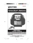
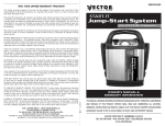
jump-start system
12 VOLT DC POWER SUPPLY
ON/OFF POWER SAFETY SWITCH
DIGITAL VOLTAGE DISPLAY
OWNER’S MANUAL
INCLUDES INSTRUCTIONS FOR 110 VOLT AC POWER INVERTER OPTION
THIS MANUAL CONTAINS IMPORTANT INFORMATION REGARDING SAFETY, OPERATION, MAINTENANCE AND STORAGE OF THIS
PRODUCT. BEFORE USE, READ AND UNDERSTAND ALL CAUTIONS, WARNINGS, INSTRUCTIONS AND PRODUCT LABELS, PLUS YOUR VEHICLE’S
BATTERY MANUFACTURER GUIDELINES. FAILURE TO DO SO COULD RESULT IN POSSIBLE INJURY OR PROPERTY DAMAGE.
4140 S.W. 28th Way, Ft. Lauderdale, FL 33312
Tel: (954) 584-4446 • Fax: (954) 584-5556 • Toll Free: (866) 584-5504
www.vectormfg.com
JUMP-START WARNINGS AND CAUTIONS
1. There is risk of explosive gas being released when batteries are improperly charged or discharged.
Failure to follow instructions may cause property damage, explosion hazard and/or personal injury.
2. Do not smoke while jump-starting.
3. Only attempt to jump-start a vehicle or boat in a well ventilated area.
4. This power system is to be used ONLY on vehicles or boats with 12 volt DC battery systems.
5. Do not wear vinyl clothing when jump-starting a vehicle - friction can cause dangerous static
electricity sparks.
6. Remove all metal jewelry - this can cause short circuits. Always use protective eye wear when
jump-starting: contact with battery acid may cause blindness and/or severe burns.
7. Do not attempt to jump-start a frozen battery.
8. Keep out of reach of children.
9. Vehicles that have on-board computerized systems may be damaged if vehicle battery is jump-started.
Before jump-starting this type of vehicle, read the vehicle’s owner manual to confirm that external
starting assistance is advised.
10. Excessive engine cranking can damage the vehicle’s starter motor. If the engine fails to start after
the recommended number of attempts, discontinue jump-start procedure and look for other
problems that may need to be corrected.
11. If vehicle to be started has a Negative Grounded System (negative battery terminal is connected to
chassis):
A. Connect positive (POS) (+) red clamp to vehicle battery’s POS (+) terminal.
B. Connect negative (-) black clamp to vehicle chassis or a solid, non-moving, metal vehicle
component or body part. DO NOT clamp directly to positive battery terminal or moving part.
If vehicle to be started has a Positive Grounded System (positive battery terminal is connected
to chassis): Replace steps 11A and 11B (above) of the jump-start procedure with the following
steps A and B, and then proceed to step 11.
A. Connect negative (-) black clamp to vehicle battery’s negative terminal.
B. Connect positive (+) red clamp to vehicle chassis or a solid, non-moving, metal vehicle
component or body part.
DO NOT clamp directly to positive battery terminal or moving part.
12. IF YOU HEAR AN AUDIBLE ALARM AND SEE THE RED LED LIGHT - DO NOT TURN ON THE
SAFETY SWITCH - THE POLARITY IS REVERSED. INTERCHANGE CLAMP POSITIONS.
13. Replace worn or defective parts immediately - contact Vector Technical Support Department at
(954) 584-4446 or toll free at 866-584-5504.
14. Skin: if battery acid comes in contact with skin, rinse immediately with water, then wash thoroughly
with soap and water. If redness, pain, or irritation occurs, seek immediate medical attention.
15. Eyes: if battery acid comes in contact with eyes, flush eyes immediately for a minimum of 15
minutes, seek immediate medical attention.
GENERAL WARNINGS
• NEVER immerse Start-It in water - it is water-resistant, not waterproof.
• When recharging the unit near water (pool, dockside, beach, etc.) do not allow the electrical
cords and outlets to get wet or come near water — electrical shock could result! Use GFCI AC
receptacles.
• Jump-starter is NOT designed to be used instead of a vehicular battery.
• NEVER insert anything other than the supplied power/recharging cables or recommended
appliance power/recharging cables into the charging/power sockets on this unit.
ALL WIRES, CABLES AND CORDS MUST BE POSITIONED SO THAT THEY CANNOT BE TRIPPED
OVER OR DAMAGED BY MOVING PARTS, BY PINCHING OR ABRADING.
V E C T O R®
TWO YEAR LIMITED WARRANTY REGISTRATION FORM
This limited warranty program is the only one that applies to this product, and it sets forth all the responsibilities of
Vector Manufacturing, Ltd., regarding this product. There is no other warranty, other than those described herein.
This Vector Manufacturing, Ltd. product is warranted, to the original purchaser only, to be free of defects in
materials and workmanship for two years from the date of purchase without additional charge. The warranty does
not extend to subsequent purchasers or users. Vector Manufacturing, Ltd. will not be responsible for any amount of
damage in excess of the retail purchase price of the product under any circumstances. Incidental and consequential
damages are specifically excluded from coverage under this warranty.
This product is not intended for commercial use. This warranty does not apply to accessories or damage to units from
misuse or incorrect installation. Misuse includes wiring or connecting to improper polarity power sources.
RETURN/REPAIR POLICY: Defective products, other than accessories, may be returned postage
prepaid to Vector Manufacturing. Any defective product, other than accessories, that is returned to Vector
Manufacturing within 30 days of the date of purchase, will be replaced free of charge. If such a product is returned
more than 30 days, but less than two years, from the purchase date, Vector Manufacturing will repair the unit or, at
its option, replace it free of charge. If the unit is repaired, new or reconditioned replacement parts may be used, at
Vector Manufacturing’s option. A unit may be replaced with a new or reconditioned unit of the same or comparable
design. The repaired or replaced unit will then be warranted under the terms of the remainder of the warranty period. The customer is responsible for the shipping charges on all returned items after 30 days. During the warranty
period, Vector Manufacturing, Ltd. will be responsible for the return shipping charges.
LIMITATIONS: This warranty does not cover accessories, bulbs, fuses and batteries, defects resulting from normal wear
and tear (including chips, scratches, abrasions, discoloration or fading due to usage or exposure to sunlight),
accidents, damage during shipping to our service facility, alterations, unauthorized use or repair, neglect, misuse,
abuse, failure to follow instructions for care and maintenance, fire, flood and Acts of God.
If your problem is not covered by this warranty, call our Technical Support Department at (954) 584-4446
or toll free at 866-584-5504 for general repair information and charges if applicable. You may also contact us
through our website at www.vectormfg.com.
STATE LAW RIGHTS: This warranty gives you specific legal rights. Some states do not allow limitations on how long
an implied warranty lasts or the exclusion or limitation of incidental or consequential damages, so the exclusions or
limitations stated herein may not apply. This warranty gives the purchaser specific legal rights; other rights, which
vary from state to state, may apply.
TO REQUEST WARRANTY SERVICE FOR THIS PRODUCT: Contact Vector Manufacturing Technical Support by telephone, fax or mail. We suggest that you keep the original packaging in case you need to ship the unit. When
returning a product, include your name, address, phone number, dated sales receipt (or copy) and a description of
the reason for return and product serial number. After repairing or replacing the unit, we will make every effort to
return it to you within four weeks.
WARRANTY ACTIVATION: Please complete Warranty Activation Card and mail to Vector Manufacturing. Enter
“TVEC012” as Model. All Vector Manufacturing, Ltd. products must be registered within (30) days of purchase to
activate this warranty. Mail the completed registration form, along with a copy of the original sales receipt to:
ATTN.: CUSTOMER SERVICE / VECTOR MANUFACTURING, Ltd.
4140 SW 28th Way, Ft. Lauderdale, FL 33312
PH: 954-584-4446 • TOLL FREE: 866-584-5504 • Fax: 954-584-5556.
You may also contact us at our web site www.vectormfg.com
Please activate my Limited Warranty for Model TVEC012
I have enclosed a copy of the original sales receipt.
Name . . . . . . . . . . . . . . . . . . . . . . . . . . . . . . . . . . . . . . . . . . . . . . . . . . . . . . . . . . . . . . . . . . . . . . . . . . . . . . . . . . . . . . . . . .
Street Address . . . . . . . . . . . . . . . . . . . . . . . . . . . . . . . . . . . . . . . . . . . . . . . . . . . . . . . . . . . . . . . . . . . . . . . . . . . . . . . . . . . .
City . . . . . . . . . . . . . . . . . . . . . . . . . . . . . . . . . . . . . . . . . . .State . . . . . . . . . . . . .Zip code . . . . . . . . . . . . . . . . . . . . . . . .
Phone . . . . . . . . . . . . . . . . . . . . . . . . . . . . . . . . . . . . . . . . . . . . . . . . . . . . . . . . . . . . . .Fax . . . . . . . . . . . . . . . . . . . . . . . .
✄
Cut here
E-mail . . . . . . . . . . . . . . . . . . . . . . . . . . . . . . . . . . . . . . . . . . . . . . . . . . . . . . . . . . . . . . . . . . . . . . . . . . . . . . . . . . . . . . . . . .
Item Purchased . . . . . . . . . . . . . . . . . . . . . . . . . . . . . . . . . . . . . . . . . . . . . . . . . . . . . . . . . . . . . . . . . . . . . . . . . . . . . . . . . . .
Date of Purchase . . . . . . . . . . . . . . . . . . . .Store Where Purchased . . . . . . . . . . . . . . . . . . . . . . . . . . . . . . . . . . . . . . . . . . . .
UPC Number from package (12 digits) . . . . . . . . . . . . . . . . . . . . . . . . . . . . . . . . . . . . . . . . . . . . . . . . . . . . . . . . . . . . . . . . . .
1
CONTENTS
1. Introduction . . . . . . . . . . . . . . . . . . . . . . . . . . . . . . . . . . . . . . . . . . . . . . .2
1.1. Additional Key Features . . . . . . . . . . . . . . . . . . . . . . . . . . . . . . . . . .3
1.2. Use The Start-It To: . . . . . . . . . . . . . . . . . . . . . . . . . . . . . . . . . . . .3,4
2. Us As A Jump-start System . . . . . . . . . . . . . . . . . . . . . . . . . . . . . . . . . . . .4
2.1. Review Of Jump-start Warnings And Cautions . . . . . . . . . . . . . . . .4,5
2.2. Jump-start Procedure . . . . . . . . . . . . . . . . . . . . . . . . . . . . . . . . . . . .5
3. Use As A 12 Volt DC Portable Power Supply . . . . . . . . . . . . . . . . . . . . . .5,6
4. Charging/Recharging . . . . . . . . . . . . . . . . . . . . . . . . . . . . . . . . . . . . . . . .6
4.1. AC Recharge . . . . . . . . . . . . . . . . . . . . . . . . . . . . . . . . . . . . . . . . . .6
4.2. DC Recharge . . . . . . . . . . . . . . . . . . . . . . . . . . . . . . . . . . . . . . . .6,7
5. Maintenance/Replacement Parts . . . . . . . . . . . . . . . . . . . . . . . . . . . . . . . .7
6. Battery Disposal . . . . . . . . . . . . . . . . . . . . . . . . . . . . . . . . . . . . . . . . . . . .7
7. Specifications . . . . . . . . . . . . . . . . . . . . . . . . . . . . . . . . . . . . . . . . . . . . . .7
8. Warranty . . . . . . . . . . . . . . . . . . . . . . . . . . . . . . . . . . . . . . . . . . . . . . . . .8
2
1. INTRODUCTION
Congratulations on selecting the Vector™ Model TVEC012 Start-It Jump-Start System. This system is an
advanced power and jump-start system with unique features that set it far above the value and utility of
ordinary jump-starters. It supplies DC for 12 Volt appliances to 20 amps. It can jump-start any vehicle
with a standard 12 Volt DC electrical system: boat, truck, car, airplane, RV, personal watercraft,
snowmobile, tractor, etc.
This advanced design is for serious work during emergencies and it can also enhance your fun by
powering DC appliances on the road, at the beach and at camp. Be sure to read and understand all
WARNINGS and CAUTIONS before using this product. Please read this guide carefully before use to
ensure optimum performance and avoid damage to the system or items that you are using it with.
The built-in LED area light is invaluable when it becomes necessary to locate battery terminals while
preparing to jump-start a dead battery in the dark. An audible polarity alarm warns of incorrect connections while preparing to jump-start a dead vehicle battery.
It is also ideal for use with Vector™ 12 Volt DC cordless, portable, rechargeable appliances with ratings
up to 20 amperes. For information about Vector appliances, contact Vector™ Customer Service for the
location of the nearest retailer.
The unit has an easy-to-read, digital voltmeter that displays the battery level. The digital display activates
whenever the charge status pushbutton is pressed and it displays the battery voltage. The display activates automatically during recharge operations to show a circulating pattern. The display shows FULL
when the battery is completely charged.
One 12 Volt DC accessory socket is provided for use with appliances that can operate from a 12 Volt DC
accessory socket. The DC accessory socket allows for DC recharge from a vehicle or other 12 volt accessory socket. Note that the exposed electrical socket and recharge port have covers that help keep out dirt,
dust and moisture. All covers must be open for socket or port use; closed after use.
FIGURE 1 Switches, Indicators and Ports on top Panel
Battery status
display
pushbutton
12 Volt DC
accessory
socket
Digital LED voltage display
(battery status display)
On/Off power
safety switch
Reverse
polarity LED
Recharge
port
Switches, LED indicators and ports are located on the top panel.
Area light
switch
The Safety Power Switch (OFF/ON) is located on the upper right side of the panel. When it is in the OFF
position, the cable clamps are not powered and the reverse polarity alarm system is enabled and ready
to sound, if connected to an incorrect polarity. A small red LED above the Vector Logo also indicates
Reverse Polarity.
On top of the Area Light “dome” is a slide switch that turns the Area Light ON and OFF. The Area Light
is powered ON when the ON/OFF slide switch is moved to the right hand side. The Area Light provides
the user with light while changing a tire, and connecting battery clamps. The area light is a long lasting
lamp and will continuously operate for three days from a fully charged battery.
11
10
3
To the left of the Area Light dome is the Recharging Port. It is covered by a rubber cap that keeps dust,
dirt, and moisture out of the socket. The recharge adapter barrel connector plugs into this port during
recharge.
The Battery Status Display is a large character, three-digit voltmeter. During AC recharge, the Battery
Status Display automatically activates with a circulating pattern. When the battery is fully charged, the
display shows FULL. To the left of the digital display is the Battery Level Status Pushbutton. Press this
Pushbutton to display the battery voltage. There is a slight delay before the actual battery voltage is displayed.
To the left of the Battery Level Status Pushbutton is a 12 Volt Accessory Socket. It is covered with a
rubber protective cap. The cap keeps dust, dirt and moisture out of the socket. When the cap is lifted, the
accessory socket can be used for powering 12 volt appliances that draw up to 20 amps current.
Figure 2 shows the storage location for the jumper clamps.
FIGURE 2
1.1. Additional Key Features
• ON/OFF safety power switch (no key required, no key to get lost!).
• Cordless/rechargeable-includes recharge adapters for standard 110-volt AC wall socket, and vehicle’s
12 Volt DC accessory outlet using adapter cables.
• Powerful-400 instantaneous cranking amps; 1200 peak amps.
• Includes non-spillable, maintenance-free, heavy duty, 19 ampere hour, sealed, lead-acid battery.
• Requires no maintenance (other than recharging) for optimum operation.
• Heavy duty, industrial grade copper clamps and welding grade jumper cables with exclusive cable holsters.
• Exclusive cable storage channels that keep jumper cables out of the way until they are needed.
• 110-volt AC charger is Underwriter Laboratories (UL) safety tested and listed.
• Easy-to-read Digital Battery Status Display - activated by pressing the Charge Status Pushbutton.
1.2. Use the Start-It to:
• Jump-start (using heavy-duty battery cable and clamps): Any vehicle with a standard 12 Volt DC
battery system: boat, truck, car, airplane, RV, personal watercraft, snowmobile, tractor, etc.
• Operate (using 20 ampere rated 12 Volt Accessory Sockets): 12 Volt DC Fans, fluorescent work lights,
cellular phones*, air compressors, spotlights, TVs, portable radios, cassette or CD players, and more.
*Can quick-charge a cellular phone by using the phone’s 12 Volt DC adapter cord.
4
• Illuminate areas: under the hood, inside tents, work areas while changing tires, etc.
Note that other Vector appliances may also be used with this jump-starter as long as they do not exceed
the 20-ampere limit of the jump-starter’s 12V DC accessory socket. For AC appliance operation we recommend the Vector VEC023 Power Inverter. It can be purchased separately and it powers AC appliances
to 175 Watts.
READ INSTRUCTION MANUAL AND PRODUCT LABELING CAREFULLY, BEFORE USING THIS PRODUCT. FOLLOW RECOMMENDED WARNINGS, CAUTIONS, AND SAFETY PROCEDURES, AND MANUFACTURER’S GUIDELINES FOR YOUR VEHICLE BATTERY.
IMPORTANT
This unit is delivered in a partially charged state - you must fully charge it before using it for the
first time. Initial AC Charge should be for 24 hours.
Refer to Section 4 for use of AC/DC Recharge Adapters and detailed charging instructions.
2. USE AS A JUMP-START SYSTEM
Read and understand all Warnings, Cautions and Notes before operating Start-It.
Warnings alert the user to hazardous conditions that can be harmful. Cautions alert the user to conditions that can cause property damage. Notes are important operational information.
2.1 Review of Jump-start Warnings and Cautions
1. There is risk of explosive gas being released when batteries are improperly charged or discharged.
Failure to follow instructions may cause property damage, explosion hazard and/or personal injury.
2. Do not smoke while jump-starting.
3. Only attempt to jump-start a vehicle or boat in a well ventilated area.
4. This power system is to be used ONLY on vehicles or boats with 12 volt DC battery systems.
5. Do not wear vinyl clothing when jump-starting a vehicle - friction can cause dangerous static
electricity sparks.
6. Remove all metal jewelry - this can cause short circuits. Always use protective eye wear when
jump-starting: contact with battery acid may cause blindness and/or severe burns.
7. Do not attempt to jump-start a frozen battery.
8. Keep out of reach of children.
9. Vehicles that have on-board computerized systems may be damaged if vehicle battery is jump-started. Before jump-starting this type of vehicle, read the vehicle’s owner’s manual to confirm that
external starting assistance is advised.
10. Excessive engine cranking can damage the vehicle’s starter motor. If the engine fails to start after the
recommended number of attempts, discontinue jump-start procedure and look for other problems that
may need to be corrected.
IF YOU HEAR AN AUDIBLE ALARM AND SEE THE RED LED LIGHT - DO NOT TURN ON THE SAFETY
SWITCH - THE POLARITY IS REVERSED. INTERCHANGE CLAMP POSITIONS.
11. If vehicle to be started has a Negative Grounded System (negative battery terminal is connected to
chassis):
A. Connect positive (POS) (+) red clamp to vehicle battery’s POS (+) terminal.
B. Connect negative (-) black clamp to vehicle chassis or a solid, non-moving, metal vehicle
component or body part. DO NOT clamp directly to positive battery terminal or moving part.
If vehicle to be started has a Positive Grounded System (positive battery terminal is connected to chassis):
Replace steps 11A and 11B (above) of the jump start procedure with the following steps A and B, and
then proceed to step 11.
9
8
5
A. Connect negative (-) black clamp to vehicle battery’s negative terminal.
B. Connect positive (+) red clamp to vehicle chassis or a solid, non-moving, metal vehicle component
or body part. DO NOT clamp directly to positive battery terminal or moving part.
12. Replace worn or defective parts immediately - contact Vector Technical Support Department at (954)
584-4446 or toll free at 866-584-5504.
13. Skin: if battery acid comes in contact with skin, rinse immediately with water, then wash thoroughly
with soap and water. If redness, pain, or irritation occurs, seek immediate medical attention.
14. Eyes: if battery acid comes in contact with eyes, flush eyes immediately for a minimum of 15
minutes, seek immediate medical attention.
2.2. Jump-start Procedure
1. Turn Off ignition and all accessories (radio, a/c, lights, cell phone, etc). Place vehicle in “park”
and set the emergency brake.
2. Make sure the unit’s Power Switch is turned OFF.
3. Observe jump-starting negative or positive ground system, as follows: Negative ground (negative
battery terminal connected to chassis) - most common.
4. Make sure Start-It’s Power Switch is turned OFF.
5. Carefully lift negative (black) jumper cable wire from storage channel starting at clamp end of cable.
6. Squeeze negative (black) clamp handle and remove clamp from holster.
7. Carefully lift positive (red) jumper cable wire from storage channel starting at clamp end of cable.
8. Squeeze positive (red) clamp handle and remove clamp from holster.
9. Connect positive (+) red clamp to vehicle’s positive battery terminal.
10. Connect negative (-) black clamp to chassis or a solid, non-moving, metal vehicle component or
body part - never clamp directly to negative battery terminal or moving part.
IF THE REVERSE POLARITY LED OR AUDIBLE ALARM SOUNDS, DO NOT TURN ON THE SAFETY
SWITCH. REVERSE THE CLAMP POSITIONS. ONLY TURN ON THE POWER SWITCH WHEN THE AUDIBLE ALARM IS SILENT AND THE RED LED IS NOT LIT.
11. Turn ON unit’s Power Switch.
12. Start vehicle (crank engine in 5-6 second bursts). If engine won’t start, seek help and go to step 15.
13. After vehicle starts turn the Power Switch to OFF position.
14. Leave engine running.
15. Remove clamps (disconnect the negative (black) clamp first; followed by the positive (red) clamp and
store cables and clamps).
16. Squeeze negative (black) clamp handles and slide clamp into holster.
17. Carefully press negative (black) jumper cable wire into storage channel.
18. Squeeze positive (red) clamp handles and slide clamp into holster.
19. Carefully press positive (red) jumper cable wire into storage channel.
20. Recharge Start-It as soon as possible.
3. USE AS A 12 VOLT DC PORTABLE POWER SUPPLY
WARNING - NEVER INSERT A CIGARETTE LIGHTER INTO ACCESSORY SOCKET.
NOTE: Make sure that the Unit’s Power Switch is ALWAYS in the OFF position when using the unit’s 12
Volt DC accessory outlet.
1. Lift up the cover of the unit ‘s 12 Volt DC socket.
2. Insert the 12 Volt DC plug from the appliance into the 12V DC accessory socket on the unit.
3. Switch on the appliance, as usual.
4. Periodically press the Battery Level Status Pushbutton to check battery status. When the battery level
reads 10.5 volts, you must recharge it as soon as possible.
6
CAUTION: DO NOT OPERATE APPLIANCES THAT DRAW MORE THAN 20 AMPS.
4. CHARGING/RECHARGING
Lead-acid batteries require maintenance to maintain a full charge and to ensure good battery life. All
lead-acid batteries suffer from self-discharge over time and more rapidly when they are at higher temperatures. Therefore, these types of batteries need periodic charging to replace energy lost through selfdischarge. When Start-It is not in use, Vector recommends that the batteries be recharged at least every
60 days using the AC/DC Recharge Adapter.
NOTE: During recharge a circulating pattern is display on the digital display
NOTE: Generally the AC/DC Recharge method ensures full charge, DC recharge can only bring the battery to the voltage of the charging source.
All batteries must be recharged as soon as possible after each use. If a battery is allowed to remain in a
discharged state, battery life will be reduced.
NOTE: RECHARGING BATTERY AFTER EACH USE WILL PROLONG BATTERY LIFE; FREQUENT HEAVY
DISCHARGES BETWEEN RECHARGES WILL REDUCE BATTERY LIFE. OVERCHARGING WILL
REDUCE BATTERY LIFE.
NOTE: PRESSING THE BATTERY LEVEL STATUS Pushbutton TURNS ON THE DIGITAL BATTERY
STATUS DISPLAY.
4.1 AC Recharge
AC Recharge requires the use of the supplied AC/DC Adapter. The adapter must be powered from
a 110 volt AC, 60 Hz North American standard AC receptacle. The AC/DC recharge adapter barrel
connector is inserted into the Recharge Port. Refer to figure 1 for the location of the Recharge Port.
FIGURE 3
Barrel connector
Make sure that all switches are turned OFF. Charge the unit, until the Battery Status Displays indicates
“FULL”. AC recharge is a taper charge and the AC Recharger can be left connected to the Jump-starter
for long periods.
4.2 DC Recharge
The Start-It Jump-starter is supplied with a DC Recharge cable. See Figure 4.
Recharging Start-It from an external DC power source requires the use of the DC Recharge Cable. This
cable has one large DC plug and one barrel connector. The DC plug is inserted into the
ACCESSORY SOCKET of the Start-It; the barrel connector is inserted into the recharge port of the
vehicle or other DC source. Periodically check the battery voltage by pressing the Battery Level Status
Pushbutton.
FIGURE 4
Barrel connector
7
MAKE SURE ALL SWITCHES ARE IN THE OFF POSITION DURING RECHARGING. THIS MAY SLOW
RECHARGE.
To check the battery status, press the Battery Status Display Pushbutton. If the Jump-starter’s battery is fully
discharged, it is recommended that the host vehicle or boat’s engine being used for recharging be left
operating while the unit is being charged using the 12 Volt DC/DC method.
WARNING: DO NOT RECHARGE UNIT FOR MORE THAN 8 HOURS MAXIMUM USING 12 VOLT DC
METHOD.
5. MAINTENANCE/REPLACEMENT PARTS
For replacement parts, charging adapters, cables, etc., contact Vector™ Technical Support:
(954) 584-4446. There are no user serviceable parts inside Start-It. Periodically, the cables and
connectors should be inspected for damage, corrosion, dust and dirt. If surfaces are dirty, they can be
wiped clean with a cloth moistened with water and a drop of detergent. Clamp contacts can be wiped
clean with a dry cloth.
WARNINGS
THERE ARE NO USER SERVICEABLE PARTS INSIDE. DO NOT OPERATE UNIT IF THERE IS ANY
EVIDENCE OF DAMAGE. THE PRODUCT MUST BE RETURNED TO VECTOR FOR TESTING
AND REPAIR. REPLACE ANY DAMAGED CABLES AND CHARGING ADAPTERS IMMEDIATELY
BEFORE FURTHER USE.
PR
BA
6. SAFE BATTERY DISPOSAL
BA
PR
ALWAYS RECYCLE
Contains a maintenance-free, sealed, non-spillable, lead acid battery, which must be
disposed of properly. Recycling is required -contact your local authority for information.
Failure to comply with local, state and federal regulations can result in fines, or imprisonment.
For more information on recycling this battery, call toll-free 1-877-288-7722
Battery Disposal Warnings
• Do not dispose of the battery in fire as this may result in an Explosion.
• Before disposing of the battery, protect exposed terminals with heavy-duty electrical tape to
prevent shorting (shorting can result in injury or fire).
• Do not expose battery to fire or intense heat as it may explode.
7. SPECIFICATIONS
Jump-start Clamps . . . . . . . . . . . . . . . . . . . . . . . . . . . . . .400 Amps - Heavy Duty Copper
Jumper Cables . . . . . . . . . . . . . . . . . . . . . . . . . . . . . . . . . . . . .Heavy Duty Welding Cable
Peak Amps . . . . . . . . . . . . . . . . . . . . . . . . . . . . . . . . . . . . . . . . . . . . . . . . . . . . . . . .1200
Instant Amps . . . . . . . . . . . . . . . . . . . . . . . . . . . . . . . . . . . . . . . . . . . . . . . . . . . . . . .400
Battery . . . . . . . . . . . . . . . . . . . . . . . . . . . . . . . . .12 Volt 19 Amp Hour, Sealed Lead-Acid
Area Light . . . . . . . . . . . . . . . . . . . . . . . . . . . . . . . . . . . . .Three High Intensity White LEDs
Accessory Socket Protection . . . . . . . . . . . . . . . . . . . . . . . . .20 Amp Self-Resetting Breaker
AC/DC Recharge Adapter . . . . . . . . . . . . . . . . . . . . . . . . . . . . . . . . .12 Volt DC@700 mA
Height . . . . . . . . . . . . . . . . . . . . . . . . . . . . . . . . . . . . . . . . . . . . . . . .12.75 in (32.39 cm)
Width . . . . . . . . . . . . . . . . . . . . . . . . . . . . . . . . . . . . . . . . . . . . . . . .11.00 in (11.26 cm)
Depth . . . . . . . . . . . . . . . . . . . . . . . . . . . . . . . . . . . . . . . . . . . . . . . . . .5.5 in (13.97 cm)
Weight . . . . . . . . . . . . . . . . . . . . . . . . . . . . . . . . . . . . . . . . . . . . . . . . . . .16 lbs (7.26 kg)
V E C T O R®
VECTOR MANUFACTURING, Ltd.
4140 S.W. 28th Way, Ft. Lauderdale, FL 33312