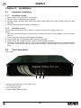
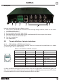
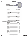
1
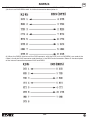
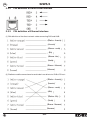
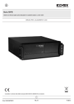
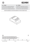
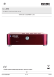
Art. 52WS/4
Net Video Server
INSTALLATION AND OPERATION MANUAL
Product is according to EC Directive 2004/108/CE, 2006/95/CE and following norms.
GB
Cod. S6I.52W.S4E
RL.00
8/2012
GB
52WS/4
INDEX
CHAPTER 1 INTRODUCTION.................................................................................................................. 3
1.1 52WS/4 FUNCTIONS AND FEATURES.................................................................................................3
1.2 COMMON APPLICATION.................................................................................................................. 3
CHAPTER 2 INSTALLATION................................................................................................................... 4
2.1 HARDWARE INSTALLATION ............................................................................................................. 4
2.1.1 Installation steps.............................................................................................................................. 4
2.1.2 Installation notice ............................................................................................................................ 4
2.2 PANEL DESCRIPTION.............................................................................................................................4
2.3 THE PIN DEFINITION OF PHYSICS INTERFACES ........................................................................... 5
2.3.1 PIN definition of RS-232 serial interface..........................................................................................5
2.3.2 PIN definition of RS485 serial interface ...........................................................................................8
2.3.3 PIN definition of Ethernet interface..................................................................................................8
CHAPTER 3 CONFIGURATION VIA WEB BROWSER............................................................................11
CHAPTER 4 FREQUENT ASK QUESTIONS......................................................................................... 11
SAFETY FOR THE INSTALLER................................................................................................................12
Thanks for purchasing the products of Elvox. If you have any requests or questions, please contact us
immediately.
This manual is applicable to 52WS/4 Net Video Server.
This manual may contain some technically incorrect places or printing errors. The contents will be updated on a regular basis without additional specific notice. The updates will be added to the new version of this manual. We will readily improve and update the products or procedures described in the
manual.
Good list
1. One piece of 52WS/4 video server;
2. A CD contains client application;
3. One power supply voltage stabilizer
4. A 220V power cable;
5. A cable connecting RS232 with DTE;
2/12
52WS/4
Chapter 1
GB
Introduction
52WS/4 net video server adopts embedded Linux operation system (RTOS) and TI DaVinci processor
that is completely independent of PC platform, and efficiently improves system performance. Firmware
is burned into the FLASH, making the system more steady and reliable.
52WS/4net video server has the function of compressing the video signal and audio signal simultaneously into H.264 compression standard; transmitting the compression stream through network; realtime video and audio preview; supporting stream protocol (RTP/RTCP, RTSP), IE browser, bi-directional
voice talk and multilingual etc.
Notes:
DS-6104HCI: 4 channels video inputs and 4 channels audio inputs. All channels can support CIF resolution real time (25FPS for PAL or 30FPS for NTSC).
1.1 52WS/4 functions and features
1.
2.
3.
2.
3.
1.
2.
3.
4.
5.
Basic Function:
High speed & high compression ratio of H.264 video hardware real-time compression;
Multiple security level leads to high system safety;
Support one RS-485 interface that can be used for controlling pan-tilt-zoom and translucent channel input.
Compression Function 1. Support four channels video (PAL/NTSC) signal, and can be real-time
hardware compressed in 25F/S (PAL) or 30F/S (NTSC) CIF resolutions independently. Video is compressed with H.264 standard, and it supports not only variable bit rate but also variable frame rate.
When choosing video image quality, you can also limit the bit rate of the compression code.
Support changeable OSD position, the date and time can be added automatically.
Support LOGO, the position is changeable in the video image.
Network Function
Support one 10M/100M Ethernet compatible interface;
Support TCP/IP protocols; support video, audio, alarm, voice data, serial device data transmission
through TCP/IP network; build-in WEB browser, support IE access.
Support pan-tilt-zoom control such as PTZ, iris and focus;
Support remote upgrading and maintenance;
RS-485 interfaces support transparent transmission mode, and remote hosts can control serial devices through it;
1.2 Common application
Network digital surveillance, such as ATM machine, factory and the bank etc;
Remote monitoring service for prison, nursery and school;
Intelligent gate system (dynamic record the people in and out);
Intelligent building and community;
Uncared-for system of electric power station or telecom base station;
Outdoor equipment monitoring;
Bridge, tunnel and cross road-monitoring system;
Pipeline, warehouse monitoring;
24 hour traffic monitoring;
Remote monitoring of forest, water and river, etc.
3/12
52WS/4
GB
Chapter 2
Installation
2.1
Hardware installation
2.1.1
Installation steps
1. Open packing case, and check the integrity;
2. Take out things needed during installation;
3. Connect cables needed (video signal input cable, audio signal input cable, RS485 cable and cable
for LAN);
4. Take out stabilizer power supply and power on.
2.1.2
Installation notice
Please read the following notice carefully. If you have any question, please contact us.
Notice:
1. After Opening the packing box, please check carefully to confirm that the goods in it are consistent
with list;
2. Please read user manual carefully before installation;
3. Please power-off all related equipments before installation;
4. Please check the voltage of power supply to avoid voltage mismatch;
5. Installation environmental: Do not use it under humidity and high temperature; to keep ventilation
vent freely, avoid being walled up; keep them horizontally, avoid setting up in the vibration surroundings.
2.2
Panel description
Front panel:
1
2
Interface Instruction (From left to right in turn)
1. Tx/Rx indicator lamp;
2. Link indicator lamp;
3. Power supply indicator lamp;
4/12
3
52WS/4
GB
Back panel:
1
2
3
4
6 7
5
Interface Instruction (From left to Right in return):
1. Power jack is connected with 12V direct current through voltage stabilizer; Please use the stabilizer power supply correctly;
2. UTP network connector;
3. 4 external alarm input and 2 relay output;
4. Standard RS-485 serial port RJ45 socket and Standard RS-232 serial port RJ45 socket;
5. 4 channels video input and audio input;
6. One line in audio input
7. One audio output.
2.3
The pin definition of physics interfaces
2.3.1
PIN definition of RS-232 serial interface
The DVS has one RS232 standard serial interface, with RJ-45 connector. Its pin definition is as follows
(‘I’ means input, and ‘O’ means output):
Table 2.1 Pin definition of RS232 serial port
Pin No
Name
I/O
Explanation
1
DCD
I
Carrier Detect
2
RxD
I
Receive
3
TxD
O
Transmit
4
CTS
I
Clear send
5
RTS
O
Request to send
6
DTR
O
Data Terminal Ready
7
GND
GND
8
(1) When the RS232 interface of the DVS connects with the DTE equipment, one end of the cable is the
8-pin RJ45 connector (to DVS) and the other of the cable is the DB25 female connector (to DTE). Below
is the description of the internal connection between RJ45 and DB25.
5/12
GB
52WS/4
(2) 25-pin to 9-pin converter’s internal connection is like this:
6/12
52WS/4
GB
(3) If you don’t want to use 25-pin to 9-pin convertor to connect DVS and DTE through RS232 interface,
you must use RJ45-DB9 cable. Its internal connection description is:
(4) When the RS232 interface of the DVS connects with the DCE (such as MODEM), one end of the
cable is the 8-pin RJ45 connector and the other is the DB25 male connector. Below is the description
of the internal connection between RJ45 and DB25:
7/12
GB
52WS/4
2.3.2
PIN definition of RS485 serial interface
2.3.3
PIN definition of Ethernet interface
(1) PIN definition of the direct network cable connecting DVS and HUB:
(Bianco - Arancio)
(Arancio)
(Bianco - verde)
(Blu)
(Bianco - blu)
(Verde)
(Bianco - Marrone)
(Marrone)
(2) Piedinatura della connessione incrociata del cavo di rete tra DVS e PC host:
(Bianco - Arancio)
(Arancio)
(Bianco - verde)
(Blu)
(Bianco - blu)
(Verde)
(Bianco - Marrone)
(Marrone)
8/12
52WS/4
Chapter 3
GB
Configuration via Web browser
Before visit the camera via web browser, user should adjust security level. Open the web browser, and
enter the menu “Tool/ internet option/Security/Custom level”, then set the security level to Security
Level - Low, or enable ActiveX Control and the Plug-in directly. Figure 3.2.1 gives you a visual illustration. After you can see the camera video, recover the security level for security.
1, Failure to control PTZ
It is possible that the camera and equipment are not connected through RS485 port, or the wrong configuration of the decoder.
2, Certain individual channel picture is un-normal
Please check whether the video cable is well connected with the camera and the Embedded DVS
3, Possible reasons which can cause the failure of upgrading
Failure of the network, IP address error in the FTP host computer, FTP service is not been booted by
PC, the path to upgrade is incorrect; no permission (usually happened when to upgrade through
client-end.)
If the above information cannot meet your demand, please not hesitate to contact the provider.
Fig. 3.1 Set the Security Level
9/12
GB
52WS/4
The default IP of the camera is 192.0.0.64 with 8000 as the default port, admin as the administrator, and
12345 as the password. The administrator can create up to 15 separate operators with different right levels.
To login the camera through IE, input the IP address in the address column, and the “Login” dialog box
will pop-up as Fig. 3.2.2. Input your user name and password, and then click “Login” to enter the “preview” page. Double click the “Camera 01” channel or “Preview” button to preview the video as Figure
3.2.3. Right click the “Camera 01” channel, and the “Main Stream”, “Sub Stream” and “Open sound”
options will popup. Select the Open sound option if you connect a pickup to the camera.
Fig. 3.2.2 Login Interface
For detailed instructions of further configuration, please refer to the user manual of network
camera V.2.00.
10/12
NOTE
Chapter 4
Frequent ask questions
1, Failure to control PTZ
It is possible that the camera and equipment are not connected through RS485 port, or the wrong configuration of the decoder.
2, Certain individual channel picture is un-normal
Please check whether the video cable is well connected with the camera and the Embedded DVS
3, Possible reasons which can cause the failure of upgrading
Failure of the network, IP address error in the FTP host computer, FTP service is not been booted by
PC, the path to upgrade is incorrect; no permission (usually happened when to upgrade through
client-end.)
If the above information cannot meet your demand, please not hesitate to contact the provider.
Specifications
Model
52WS/4
Video compression
H.264
Encode/Decode resolution 4CIF/DCIF/2CIF/CIF/QCIF
Video input
4
Video input interface
BNC (1.0Vp-p, 75Ω), support PAL, NTSC
Frame rate (per channel)
4CIF/DCIF/2CIF: 4fps for 4-ch
CIF: 25(P)/30(N) fps
Stream type
Video / Video&Audio
Support dual stream
Yes
Bit rate
32Kbps~2Mbps adaptive (Max. 8Mbps)
Audio input
4
Audio input interface
BNC (2Vp-p, 1kΩ)
Audio output
1 channel (linear electrical level, 600Ω)
Audio compression
OggVorbis, 16Kbps
Voice talk input
1 channel (2Vp-p, 1kΩ)
Communication interface
1 RJ45 10M/100M Adaptive Ethernet interface, 1 RS232 interface and
1 RS485 interface
Alarm input
4 channels
Alarm output
2 channels
Power supply
12V DC
Power consumption
≤20W
Working temperature
-10 ~+55
Working humidity
10%~90%
Size(mm)
39mm(H)*198mm(W)*123mm(D)
Weight
≤1 Kg
Stabilizer power suppler: input AC 100-240V47-63Hz
11/12
SAFETY INSTRUCTIONS FOR INSTALLERS
- Carefully read the instructions on this leaflet: they give important information on the safety, use and maintenance of
the installation.
- After removing the packing, check the integrity of the set. Packing components (plastic bags, expanded polystyrene
etc.) are dangerous for children. Installation must be carried out according to national safety regulations.
- It is convenient to fit close to the supply voltage source a proper bipolar type switch with 3 mm separation (minimum) between contacts.
- Before connecting the set, ensure that the data on the label correspond to those of the mains.
- This apparatus must only be used for the purpose for which it was expressly designed, e.g. for audio or video door
entry systems. Any other use may be dangerous. The manufacturer is not responsible for damage caused by improper, erroneous or irrational use.
- Before cleaning or maintenance, disconnect the set.
- In the event of faults and/or malfunctions, disconnect from the power supply immediately by means of the switch
and do not tamper with the apparatus.
- For repairs apply only to the technical assistance centre authorized by the manufacturer.
- Safety may be compromised if these instructions are disregarded.
- Do not obstruct opening of ventilation or heat exit slots and do not expose the set to dripping or sprinkling of water.
No objects filled with liquids, such as vases, should be placed on the apparatus.
- Installers must ensure that manuals with the above instructions are left on connected units after installation, for
users' information.
- All items must only be used for the purposes designed.
- WARNING: to prevent injury, this apparatus must be securely attached to the floor/wall in accordance with the installation instructions.
- This leaflet must always be enclosed with the equipment.
Directive 2002/96/EC (WEEE)
The crossed-out wheelie bin symbol marked on the product indicates that at the end of its useful life, the product must be handled separately from household refuse and must therefore be assigned to a differentiated
collection centre for electrical and electronic equipment or returned to the dealer upon purchase of a new,
equivalent item of equipment.
The user is responsible for assigning the equipment, at the end of its life, to the appropriate collection facilities.
Suitable differentiated collection, for the purpose of subsequent recycling of decommissioned equipment and environmentally compatible treatment and disposal, helps prevent potential negative effects on health and the environment
and promotes the recycling of the materials of which the product is made. For further details regarding the collection
systems available, contact your local waste disposal service or the shop from which the equipment was purchased.
Risks connected to substances considered as dangerous (WEEE).
According to the WEEE Directive, substances since long usually used on electric and electronic appliances are considered dangerous for people and the environment. The adequate differentiated collection for the subsequent dispatch of
the appliance for the recycling, treatment and dismantling (compatible with the environment) help to avoid possible negative effects on the environment and health and promote the recycling of material with which the product is compound.
SALES OFFICES IN ITALY
INTERNATIONAL SALES OFFICES
Milan
ELVOX Austria GmbH
Via Conti Biglia, 2
20162 Milan
Grabenweg 67
A-6020 Innsbruck
Turin
ELVOX Shanghai Electronics Co. LTD
Strada del Drosso, 33/8
10135 Turin
Room 2616, No. 325 Tianyaoqiao Road
Xuhui District
200030 Shanghai Cina
CERT n° 9110.ELVO
ELVOX Costruzioni elettroniche S.p.A. - ITALY
Via Pontarola, 14/a - 35011 Campodarsego (Padova)
Tel 049 9202511 - Fax 049 9202603 - [email protected]
Telefax Export Dept. +39/049 9202601 - [email protected]
www.elvox.com
UNI EN ISO 9001:2008