1
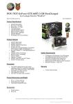
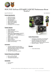
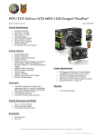
P160
User’s Manual
Manuel de l’utilisateur
Anwenderhandbuch
Manuale per l’operatore
Manual del usuario
At Antec, we continually refine and improve our products to ensure the highest
quality. So it's possible that your new P160 case may differ slightly from the
descriptions in this manual. This isn't a problem; it's simply an improvement. As
of the date of publication, all features, descriptions, and illustrations in this
manual are correct.
Disclaimer
This manual is intended only as a guide for Antec's Computer Enclosures. For detailed instructions
on installing your motherboard and peripherals, please refer to the user manuals supplied with your
components and drives.
P160 User's Manual
We don't include a power supply with the P160, so you're free to choose one
that best suits your needs. Make sure you choose a PS/2 size power supply
that conforms to the ATX standard and is compatible with your motherboard.
Most systems conform to either the ATX12V or ATX2.03 standards.
Setting Up
1. Take the case out of the box. Remove the Styrofoam and plastic bag.
2. Put the case on a flat surface.
3 Remove the thumbscrews from the back of the side panel that has the
circular latches. Unlock the panel by turning the latch handles at the top of
the panel counter-clockwise. Open the panel by swinging it down. Then pull
it away from the case and set it aside.
4. Inside the case, you'll see wiring with marked connectors (USB, PWR, etc.)
and an installed I/O panel. You'll also find a bag of hardware (screws,
brass standoffs, drive rails, etc.).
5. Remove the front bezel by pulling it away from the case. Start at the
bottom, detach the middle, and finish with the top. Remember to disconnect
the wiring from the front bezel. Set the bezel safely aside.
Installing the Power Supply
1. With the case upright, place the power supply on the support beam that
runs from the 5.25" drive bays to the back of the case. Note: most dualfan power supplies should be installed with the second fan towards the
bottom of the case.
2. Push the power supply to the back of the case and align the mounting holes.
3. Attach the power supply to the case, using the screws provided.
Installing the Motherboard
This manual does not cover CPU, RAM, or expansion card installation. Please
consult your motherboard manual for specific mounting instructions and
troubleshooting.
1.
2.
Lay the case down, with the open side facing up. The drive cages should
be visible.
Make sure you have the correct I/O panel for your motherboard. If the panel
provided with the case isn't suitable, please contact your motherboard
manufacturer for the correct I/O panel.
1
3.
You'll see a removable motherboard tray inside
the case. Unscrew the thumbscrews on the
tray retaining plate (see Photo 1) and remove it.
4. Slide the motherboard tray towards the drive
cage and pull up to remove it. Place the tray
Photo 1
on a flat surface.
5. Line up your motherboard with the standoff holes, and
remember which holes are lined up. Not all motherboards will match with
all of the provided holes; this is normal, and won't affect functionality.
6. Screw the brass standoffs into the threaded holes that line up with your
motherboard. Do not overtighten the standoffs. Some standoffs may be
pre-installed for your convenience.
7. Place your motherboard on the brass standoffs.
8. Attach your motherboard to the standoffs with the provided Phillips-head
screws. Your motherboard is now installed.
9. Replace the motherboard tray in the case and slide it into position.
10. Reinstall the motherboard tray retaining plate.
Connecting the Front Control Panel with Temperature Display
The P160 includes a front control panel that can rotate up to 45 degrees. It
contains Power and Reset buttons, two USB 2.0-compatible ports, one IEEE
1394 (FireWire, i.Link) port, Audio In/Out jacks and a temperature display. To
power the LED temperature display, connect a 4-pin power connector from the
power supply to the 4-pin connector that powers the front panel.
Connecting the Power Switch and LEDs
1. Connect the 20-pin ATX power connector from your power supply (and
AUX or +12V connectors if appropriate) to your motherboard.
2. The Reset switch (labeled RESET SW) connects to your motherboard at the
RST connector. Make sure you always attach the colored wire to Pin 1,
and the black wire to ground.
3. Connect the Power Switch (labeled POWER SW) to the PWR connector on
the motherboard.
4. Connect the Power LED (labeled POWER) and HDD LED connectors to the
appropriate headers on your motherboard.
5. Decorative Blue LED: The P160's front panel includes three decorative blue
LEDs over each of the front air intake vents. Locate the Molex 4-pin male
connector from the bezel and connect it to a 4-pin connector from the
power supply. The LEDs will light when you power-up your system.
Connecting the USB Ports
There are two black, 5-pin USB connectors on cables attached to the front
bezel. Here's how to connect them to your motherboard headers:
1.
Check the USB pin layout in your motherboard user manual and make sure
it follows this standard pinout:
Pin 1: USB Power - may also be labeled +5V
Pin 2: Negative Signal - may also be labeled P-, D-, USB0-, etc.
Pin 3: Positive Signal - may also be labeled P+, D+, USB0+, etc.
Pin 4: Ground
Pin 5: Ground
2
2.
Note: Your motherboard's USB pin layout may differ from this common
standard. If you're unsure of your motherboard's layout, please contact
technical support at your motherboard's manufacturer.
Plug the 5-pin USB connectors onto the header rows so that the RED wire
is on Pin 1 (Power, or +5V). The second header may be reversed (Power
pin at the opposite end of the row) so be careful when you plug in both
connectors.
Connecting the IEEE 1394 (FireWire, i.Link) Ports
There are six wires with connectors attached to the front-mounted IEEE 1394
port of the P160. They consist of 2 sets of twisted pair cables: TPA (Twisted
Pair A) and TPB (Twisted Pair B,) a power cable (VP,) and a ground cable (VG)
1.
2.
3.
4.
Locate and identify the pin-out of the IEEE 1394 port on your motherboard.
Note: DO NOT connect the IEEE 1394 connectors to your motherboard's
USB header. This could cause permanent damage to your motherboard.
Connect the VP connector to the Power pin.
Connect the VG connector to the Ground pin.
There are two sets of data pins. Each set consists of a plus and a minus
pin. They are usually marked as TPA+ and TPA-, TPB+ and TPB-.
a. Connect the TPA+ connector to the TPA+ data pin and TPA- connector
to the TPA- data pin.
b. Connect the TPB+ connector to the TPB+ data pin and TPB- connector
to the TPB- data pin.
Connecting the Audio Ports
The front panel speaker and microphone connection features an Intel-standard
10-pin connector, with 7 additional individual wires and connectors. If your
motherboard supports Intel's standard onboard audio connector, you can plug
the 10-pin connector directly into the board. Otherwise, you'll need to attach
the 7 individual connectors to the motherboard. Here's how:
Locate the internal audio connectors on your motherboard or sound card.
Consult your motherboard or sound card manual for the pin-out positions.
1.
2.
3.
4.
5.
6.
7.
Connect the MIC connector to the microphone power pin.
Connect the MIC-BIAS connector to the microphone input pin.
Connect the AUD GND connector to the ground pin.
Connect the FPOUT-R connector to the Front Right Speaker Out Pin.
Connect the FPOUT-L connector to the Front Left Speaker Out Pin.
Connect the RET-R connector to the Rear Right Speaker Out Pin.
Connect the RET-L connector to the Rear Left Speaker Out Pin.
Note: If your motherboard doesn't support rear speaker output, you don't
need to connect the RET-R or RET-L connectors.
Connecting the Temperature Display Sensor
There are two temperature sensors connected to the front display. Every 3
seconds, the temperature display cycles automatically between them.
1.
There are two 26" (66 cm) long temperature sensor wires. For best
temperature monitoring, we suggest you connect one sensor to the hard
3
2.
drive and the other to the motherboard.
There is a 26" (66 cm) long cable with a switch connected to the front
control panel. The switch toggles the temperature display between
Celsius (C°) and Fahrenheit (C°). The default setting is Celsius (C°).
Installing 5.25" Devices
The P160 features four external 5.25" drive bays. You'll find the drive rails
inside the toolbox.
1.
2.
3.
4.
5.
6.
Remove the front bezel by grasping it at the bottom and swinging upwards.
Carefully remove the sheet metal covering the drive bay by twisting it back
and forth until it separates from the case. Watch your fingers; when you
remove the sheet metal, there may be a sharp metal burr remaining where
the plate was attached.
Mount two drive rails onto the sides of the 5.25”
#2
#1
device. Make sure the metal tab angles out away
from, and faces towards, the front of the device.
Note: If you want to mount your drive flush to the
front bezel, use the first screw hole on the rails
(marked #1 in Photo 2) to mount the drive rails. If
Photo 2
you want to use one of the color-coordinated CDROM cover plates included with the P160, mount
the rails with the second screw hole (marked #2 in Photo 2).
Slide the device into the drive bay until you hear a click.
Mount the other devices accordingly.
Connect a large 4-pin white connector from the power supply to the male
4-pin connector on each of the devices.
Installing External 3.5" Devices
You'll find two external 3.5" drive bays underneath the 5.25" drive bays.
1.
2.
3.
4.
5.
With the front bezel removed, unscrew the two thumbscrews at the sides
of the 3.5" drive tray and pull the 3.5" drive tray out of the case.
Mount your floppy drive or other external device in the drive tray. If needed,
repeat the same procedure for the other
drive.
#1
Note: We've included one color-coordinated
floppy drive cover plate with the P160. If
#2
you want to use the cover plate, leave
enough room for it when mounting the
Photo 3
drive (as indicated by #1 in Photo 3).
If you want your device to sit flush to the bezel front, use the other set of
mounting holes (as indicated by #2 in Photo 3).
Slide the drive tray back into the case and fasten it with the thumbscrews.
Remove the drive bay cover from the drive bay that you intend to use.
Find a small 4-pin white power connector on the power supply and connect
it to the male 4-pin connector on the device.
Installing Internal 3.5" Devices
The P160 features four internal hard drive bays under the external 3.5 drive
bays. Each bay includes an individual drive tray which mounts through the
4
open side panel of the case.
1.
2.
3.
4.
5.
Squeeze the metal clips on each side of the tray and slide the tray out.
Mount your hard drive or other internal 3.5" device into the drive tray by
threading the special screws through the bottom rubber grommets. Don't
over-tighten the screws, since that could decrease the grommets' vibration
and noise absorbing ability.
Slide the tray back into the case and lock it.
Connect a 4-pin white molex connector on the power supply to the male
4-pin connector on the device.
If needed, repeat the same procedure for the other drives.
Note: You can mount the drives with the connectors facing toward or away
from you. If you mount them with the connectors facing away (into the
case) you may wish to connect the data cables before sliding the drive into
the locked position. If you are installing Serial ATA drives we recommend
positioning the drives so that the connectors face you.
Connecting Data Cables
After you've connected the devices to the power supply, you need to connect
the data cables between the devices and the motherboard. Although data
cables aren't included with the P160, here are some useful tips:
1.
2.
3.
For hard drives and CD-ROMs, use 40-pin IDE ribbon cables. For floppy
drives, use 34-pin ribbon cables. These cables should be included with your
drives, and should have a red strip on one side indicating pin number 1.
When you connect a ribbon cable to a device, make sure that the red strip
is on pin 1, usually toward the power connector.
Attach the side with 2 connectors to the devices. This allows you to
connect another device if you wish.
Connect the far end of the cable to your motherboard on the IDE port,
either IDE 1 or IDE 2, or the FLOPPY port.
Note: If you wish to connect a 3.5" drive and a 5.25" drive on the same
IDE channel, we recommend that you use IDE cables which provide 10 or
more inches of flexible cable between connectors or the start of any protective
boot. We suggest you mount the 3.5" drive in the topmost 3.5" drive bay
and the 5.25" drive in the bottom 5.25" drive bay.
of the case. Connect the power supply to the fan by
using the 4-pin connector.
The optional front fan should be installed so that the air
blows into the case from the front. For Quiet Computing™
we recommend that you NOT install the front fan unless
necessary for cooling, since it will create additional noise.
To mount the front fan:
1.
2.
3.
4.
Un-screw the thumbscrew and pull the fan bracket out.
Install the fan into the bracket.
Carefully guide the fan cable through the cut-out on the side of the bracket
while inserting the fan bracket into the slot.
Tighten the thumbscrew.
Maintaining the Washable Air Filter
The P160 includes a washable air filter behind the front grill. To access it, simply
remove the front bezel. Initially, we recommend washing the air filter at least
once a month. By keeping the air filter clean, you'll help your system remain
stable and cool.
Antec Quality 3-Year parts and labor warranty (AQ3)
See details at: http://www.antec-inc.com/warranty.html
Installing the Fan
We've included one rear-mounted 120mm cooling fan
with vibration-reducing rubber grommets, and one optional
front-mounted 120mm cooling fan.
Here’s how to install the rear case fan:
Step 1. Align the pre-installed fan fasteners with the
four fan mounting holes on the case.
Step 2. Pull the fasteners fully through the mounting
holes on the case. Note: don’t use excessive
force, or any tools, to pull the fasteners.
Step 3. Trim the excess material.
The rear fan should be installed so that the air blows out
5
Step 3
Step 1
Step 2
6
P160
Anodized Aluminum Super Mid Tower Case
1
2
3
Drawing
4
5
6
7
8
9
19
18
17
16
15
14
13
12
11
10
Description
Number
1
Left Side Panel
2
I/O Panel
3
Top Panel
4
Removable Motherboard Tray
5
Right Side Panel
6
Front Control Panel Display Assembly
7
Drive Rails (Drives not included)
8
5.25” Drive Bay Cover
9
3.5” Drive Bay Cover
10
Front Panel
11
Washable Air Filter
12
3.5” Drive Bay Tray (Drives not
included)
13
Rubber Feet
14
3.5” Internal Drive Bay Tray (Drives not
included)
15
Fan Bracket
16
Expansion Slot Covers
17
Side Panel Latch
18
Side Panel Latch with Key Lock
19
Thumbscrews