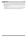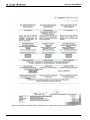
1
MSI-SR4
EN 2010/11 - 607393
We reserve the right to
make technical changes
Safety Relays
SAFE IMPLEMENTATION AND OPERATION
Original operating instructions
Safety sequential circuit and protective door monitors in accordance with IEC-, EN 60204-1 stop
category 0, depending on the wiring up to cat. 4 (EN ISO 13849-1: 2009)
These instructions contain information on the approved purpose and are part of the delivery contents.
Leuze electronic GmbH + Co.KG is not liable for damages that result from improper use. Proper use also
includes knowledge of the information contained in these instructions.
© 2010
Leuze electronic GmbH + Co. KG
In der Braike 1
D-73277 Owen - Teck / Germany
Phone: +49 7021 573-0
Fax: +49 7021 573-199
http://www.leuze.com
[email protected]
Contents
1
Product description ....................................................................................................................................................... 4
1.1
1.2
System overview........................................................................................................................................................... 4
Application possibilities ................................................................................................................................................. 4
2
Safety............................................................................................................................................................................ 5
2.1
2.2
2.3
2.4
2.5
2.6
Symbols ........................................................................................................................................................................ 5
Proper use .................................................................................................................................................................... 5
Foreseeable misuse ..................................................................................................................................................... 6
Competent personnel ................................................................................................................................................... 6
Responsibility for safety ................................................................................................................................................ 6
Disposing ...................................................................................................................................................................... 6
3
Function ........................................................................................................................................................................ 7
4
Start-up ....................................................................................................................................................................... 10
4.1
4.2
4.3
Electrical installation / installation instructions ............................................................................................................ 10
Display and control elements...................................................................................................................................... 10
Tests ........................................................................................................................................................................... 11
5
Technical data MSI-SR4 ............................................................................................................................................. 12
Leuze electronic
MSI-SR4
3
Product description
1
Product description
The MSI-SR4 E-STOP relay is used as a connecting element between Optoelectronic Protective Devices
of type 3 or 4 as well as a sequential device for 1- or -2-channel protective-door and E-STOP monitors and
the machine control.
1.1
System overview
• 1- or 2-channel E-STOP circuit
• Cross-circuit recognition
• Monitoring of external contactors in the button circuit
• Monitored start button (cross connections between the button contacts and earth faults in the button
circuit are detected.)
• Automatic and manual start
• 3 release circuits, 1 NC contact as auxiliary power circuit
• LED displays Power, K1 and K2, reset
• Operating voltage 24 V AC/DC
• Housing width, 22.5 mm
1.2
Application possibilities
• Single-channel E-STOP circuit, (up to category 2, EN ISO 13849-1: 2009)
• Two-channel E-STOP wiring with cross-circuit recognition (up to category 4, EN ISO 13849-1: 2009)
• Single-channel protective door monitoring (up to category 2, EN ISO 13849-1: 2009)
• Two-channel protective door monitoring (up to category 4, EN ISO 13849-1: 2009)
• Sequential circuit for Light Beam Safety Devices type 4 with relay- or semiconductor outputs
• Sequential circuit for Light Beam Safety Devices type 2 (two-channel, self-testing)
Leuze electronic
MSI-SR4
4
Safety
2
Safety
Before using the E-STOP relay, a risk evaluation must be performed according to valid standards and
regulations.
For mounting, operating and testing, this document as well as all applicable national and international standards and regulations must be observed, printed out and handed to the affected personnel.
ª Before working with the E-STOP relay, completely read and understand the documents applicable to
your task.
In particular, the following national and international legal regulations apply for the start-up, technical
inspections and work with E-STOP relays:
• Machinery directive 2006/42/EC
• Use of Work Equipment Directive 89/655/EEC supplemented by Directive 95/63 EC
• Accident-prevention regulations and safety rules
• Other relevant standards
• Standards
2.1
Symbols
Warning sign – This symbol indicates possible dangers. Please pay especially close
attention to these instructions!
2.2
Proper use
The E-STOP relay must only be used after it has been selected in accordance with the respectively applicable instructions and relevant standards, rules and regulations regarding labor protection and occupational safety, and after it has been installed on the machine, connected, commissioned, and checked
by a competent person.
WARNING
Improper or inappropriate use can result in danger to the life and limbs of the machine operator
or in damage to property.
• The safety interface device must be tested regularly by competent personnel.
• Two switching contacts must always be looped into the switch-off circuit of the machine. To prevent
welding, relay switching contacts must be fused/protected externally according to the technical data.
• The safety interface device must be exchanged after a maximum of 20 years. Repairs or the
exchange of parts subject to wear and tear do not extend the service life.
• If an AOPD or other recommended safety component with lower safety category or Performance
Level is connected, the overall safety level for the corresponding path of the control cannot be higher
than that of the connected safety components.
• The control of the machine or system that is to be safeguarded must be electrically influenceable. A
switch-off command initiated by an MSI must result in an immediate shutdown of the dangerous
movement.
• The "Reset" acknowledgment button for unlocking the start/restart interlock must be mounted in such
a way that the entire danger zone can be seen from its mounting location.
• Message outputs (state outputs) must not be used for switching safety-relevant signals.
• In the event of changes to the MSI-SR4, all warranty claims against the manufacturer of the safety
interface device are rendered void.
• Depending on external wiring, dangerous voltages may be present at the switching outputs. In addition to the power supply, these must be switched off and safeguarded against being switched back on
prior to all work on the MSI.
• For contact multiplication of the release circuit, switching elements with positive-guided contacts
must be used.
Leuze electronic
MSI-SR4
5
Safety
NOTICE
Also observe the safety and warning notices in the documentation of the connected protective
devices.
2.3
Foreseeable misuse
Any use other than that defined under the “approved purpose” or which goes beyond that use is considered improper use!
e.g.
• The MSI-SR4 is not suited for applications in explosive or easily flammable atmospheres.
2.4
Competent personnel
Prerequisites for competent personnel:
• has a suitable technical education
• he knows the instructions for the E-STOP relay and the machine
• has been instructed by the responsible person on the mounting and operation of the machine and of
the E-STOP relay
2.5
Responsibility for safety
Manufacturer and operating company must ensure that the machine and implemented E-STOP relay function properly and that all affected persons are adequately informed and trained.
The manufacturer of the machine is responsible for:
• safe implementation of the E-STOP relay
• imparting all relevant information to the operating company
• adhering to all regulations and directives for the safe starting-up of the machine
The company operating the machine is responsible for:
• instructing the operating personnel
• maintaining the safe operation of the machine
• adhering to all regulations and directives for occupational safety and safety at work
• regular testing by competent personnel
2.6
Disposing
For disposal observe the applicable national regulations regarding electronic components.
Leuze electronic
MSI-SR4
6
Function
3
Function
A1 (+24V)
~
13 23 33 41
S33 S34 S35 S31 S22
+
=
CH1
K1
MSI- SR4
0V
0V
MSI-SR4
+24V
14 24 34 42
S12
A2 (0V)
N.O.
K2
N.O.
N.O.
CH2
MSI-SR4
+24V
A1
A1
S22
S22
S12
S12
S31
S31
S33
S33
S34
S34
K4
K5
S35
S35
A2
A2
2
1
Figure 3.1:
Connection example 1
0V
Figure 3.2:
0V
MSI-SR4
AOPD, Type 4
OSSD1
OSSD2
+24V
Connection example 2
MSI-SR4
+24V
A1
S22
A1
S22
AOPD, Type 4
S12
S12
S31
S31
+24V
S33
S33
S34
S34
K4
S35
A2
K5
S35
A2
3
Figure 3.3:
Leuze electronic
Connection example 3
4
Figure 3.4:
MSI-SR4
Connection example 4
7
Function
0V
MSI-SR4
closed
open
+24V
A1
S22
S12
S31
S33
S34
S35
A2
5
Figure 3.5:
Connection example 5
Single-channel E-STOP circuit, manual start
(see figure 3.1)
After applying the supply voltage to A1 and A2 and with the E-STOP button not actuated, relays K1 and
K2 pick up upon actuation of the start button and lock. The release circuits 13-14, 23-24 and 33-34 close,
signal circuit 41-42 opens. Upon actuation of the E-STOP button, K1 and K2 go dead and drop out. The
release circuits open, the signal circuit closes. With one-channel E-STOP wiring, up to category 2 acc. to
EN ISO 13849-1: 2009 is achieved. Earth faults in the button circuit are detected.
Two-channel E-STOP circuit, manual start
(see figure 3.2)
Function/operating principle as described above. In addition, contactor contacts K1 and K2 are looped into
the start circuit (reset) (EDM).
With two-channel E-STOP wiring, up to category 4 acc. to EN ISO 13849-1: 2009 is achieved.
Downstream safety circuit for Optoelectronic Protective Devices type 4, EN 61496-1
(see figure 3.3), (see figure 3.4)
Optionally, Light Beam Safety Devices of type 4 can be connected with relay outputs (see figure 3.3) or
with fail-safe semiconductor outputs (see figure 3.4). When calculating the safety distance, the regression
delay of the MSI-SR4 of 10 ms must be included. As an alternative to the start circuit, a bridge can be
placed between S34 and S35 for automatic start. With this operating mode, it must not be possible to reach
or step behind the Light Beam Safety Device.
Two-channel sliding safety guard monitoring
(see figure 3.5)
Based on the specified signal sequence, when using two, forced position switches, the direction-dependent actuation of the contacts, e.g. of a safety guard, is monitored. For automatic start (bridge S34 - S35),
reaching or stepping behind must not be possible.
Signal sequence monitoring
The function expects the first signal at S22 and the second signal at S12. The time offset is arbitrary. If,
due to, e.g., misalignment of a contact actuator, the times of the signals are swapped, this is tolerated up
to max. 20 ms. Afterwards, the release circuits of the MSI-SR4 close. Signal sequence monitoring is only
active if wired for automatic start. The EDM signal must be applied for max. 20 ms at S12 after the signal
is received.
Monitoring of the S inputs
In the event of a cross connection at inputs S12 and S22 or of a short circuit of input S12 to ground, output
relays K1 and K2 are switched off via an electronic fuse. The MSI-SR4 is again ready for operation approx.
2 s after the cause of the malfunction has been eliminated.
Leuze electronic
MSI-SR4
8
Function
Start button monitoring during manual start
(see figure 3.1), (see figure 3.2), (see figure 3.3)
To detect static faults or blocking of the start button, the button function is monitored for signal changes.
Enabling occurs when the button is released (1/0 signal change). During automatic start (see e.g.
figures 3.4, 3.5), this function is deactivated.
Contactor monitoring (EDM) with manual start
(see figure 3.2)
For function monitoring of the external contactors, their NC contacts (K4, K5) are looped into start circuit
S35 with start button in series.
Contactor monitoring (EDM) with automatic start
(see figure 3.4)
For function monitoring of the external contactors, their NC contacts (K4, K5) are looped in between S34
and S35 in series.
Leuze electronic
MSI-SR4
9
Start-up
4
Start-up
WARNING
ª Prior to the initial start-up on a power-driven machine, a competent person must inspect the connection
of the connected protective device at the MSI-SR4 as well as the integration of the complete system
in the machine control.
ª Before switching on the supply voltage for the first time, it must be ensured that the outputs of the MSI
have no effect on the machine. The switching elements that ultimately bring the dangerous machine
into motion must be safely switched off or disconnected and protected against being restarted.
ª The same safety measures apply after each function change, after repairs or during maintenance work
4.1
Electrical installation / installation instructions
WARNING
The general safety notices in Chapter 2 are to be observed.
• The MSI-SR4 is not suitable for free wall mounting and must be installed in a protective housing with
protection rating IP 54/NEMA 3 or higher. Depending on the environmental conditions at the end
user, a suitable protective housing type must be determined and used.
• Connections 13; 14; 23; 24; 33; 34; 41; 42 are equipped with reinforced insulation vis-à-vis the housing and the other connections (see chapter 3 „Function“). The mixed connection of protective extra
low voltage and low voltage (e.g. 230~) at terminals 13; 14; 23; 24; 33; 34; 41; 42 is not permitted.
• Finger-safe acc. to DIN VDE 0106 part 100, maximum stripped length of the connection cables:
8 mm
• To prevent welding of the output contacts, an external fuse of max. 5 A quick-action or 3.15 A delayaction must be interposed.
• S33 is not intended for the operation of external devices, rather only for supplying potential-free contacts.
• Shutdown of the supply voltage for operational purposes is to be made impossible.
• Acc. to EN ISO 13849-1: 2009, cables for A2 and S22 are to be laid separately to 0 V.
• The cables at inputs S are to be laid protected , separated from 0V/+24V, and without parallel connection to third components.
• When wiring potential-free contacts at inputs S22, S12, a safety fuse is to be interposed acc. to
DIN EN 50156-1. Observe the operating instructions for the connected components.
4.2
Display and control elements
111
13 23 33 41
A1 S35 S33 S22
MSI-SR4
99.0
Supply
a
b
c
d
K1
K2
Reset
S12 A2 S34 S31
14 24 34 42
113.6
22.5
a
b
c
d
Leuze electronic
= Supply voltage on (green LED)
= Relay K1 picked up (green LED)
= Relay K2 picked up (green LED)
= Restart interlock locked (yellow LED)
MSI-SR4
10
Start-up
4.3
Tests
The test prior to the first start-up as well as regular tests by competent persons are intended to ensure that
the protective devices and any other protective components are correctly selected and provide the
required protection when properly used acc. to the local regulations, particularly the machinery and work
equipment directive (and, in Germany, the Ordinance on Industrial Safety and Health (Betriebssicherheitsverordung - BetrSichV) as well).
ª Test the effectiveness of the protective devices on the machine in all operating modes that can be set
on the machines.
ª Test the protective device according to the local regulations and standards, e.g. IEC 62046, BetrSichV
ª Observe the regulations regarding the instruction of the operating personnel by competent persons
before they begin their work. Training is the responsibility of the operating company.
Leuze electronic
MSI-SR4
11
Technical data MSI-SR4
5
Technical data MSI-SR4
Category acc. to EN ISO 13849-1: 2009
4
Performance Level (PL) in accordance with
EN ISO 13849-1
PL e
Average probability of a failure to danger per 2.0 x 10⁻⁸
hour (PFHd)
B10d
DC 13: 10.0 million switching cycles
AC 15: 1.4 million switching cycles
Mean time to dangerous failure (MTTFd)
73 years
Service life (TM)
20 years
Stop category
Stop 0 acc. to IEC 60204-1
Operating voltage UB
24 V AC/DC, ±20%
Power consumption
3W
External safeguarding for supply circuit
200 mA delay-action
Output contacts
3 normally open contacts, 1 normally closed contact (Ag
alloy)
Switching capacity of the contacts acc. to
EN 60947-5-1
AC-15: 230V / 5A 1.6 x 10⁵ switching cycles
DC-13: 24V / 3A 1.3 x 10⁵ switching cycles
Max. continuous current per current path
3A
Ext. contact fuse protection per current path
5 A quick-action or 3.15 A delay-action
Max. switching frequency
3600 switching cycles/h
Mechanical life time
10 million switching cycles
Pickup delay – manual start
30 ms
Pickup delay (autom. start)
300 ms
Regression delay, response time
10 ms
Max. test pulse acceptance
1 ms
Time window for signal sequence monitoring 20 ms
Control voltage/current on S12, S22, S31
24V DC / 40 mA
Max. input current
100 mA
Admissible input line resistance
< 30 W
Operating temperature
0° to +55° C
Storage temperature
- 25° to +70° C
Overvoltage category
Dirt level
III for rated operating voltage 300 V AC
in accordance with VDE 0110 part 1
2
Interference emission
EN 55011, DIN EN 61000-6-3
Interference rejection
EN 61496-1: 2005 type 4
Protection rating
Housing IP 40, terminals IP 20
Leuze electronic
MSI-SR4
12
Technical data MSI-SR4
Connection cross-sections
1 x 0.2 to 2.5 mm2, fine-wired or
1 x 0.25 to 2.5 mm2, fine-wired with wire-end sleeves
2 x 0.5 to 1.5 mm2, fine-wired with Twin wire-end sleeves
1 x 0.2 to 2.5 mm2, single-wired or
2 x 0.25 to 1.0 mm2, fine-wired with wire-end sleeves
2 x 0.2 to 1.5 mm2, fine-wired
2 x 0.2 to 1.0 mm2, single-wired
Dimensions (H x W x D)
99 x 22.5 x 111.5 mm
Weight
170 g
Order No.
549986
Leuze electronic
MSI-SR4
13
Technical data MSI-SR4
You can download thisEC Declaration of Conformity as a PDF from: http://www.leuze.com/relays
Leuze electronic
MSI-SR4
14