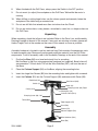
1
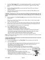
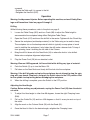
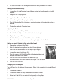
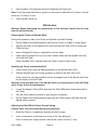
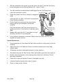
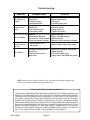
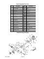
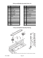
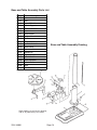
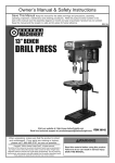
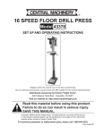
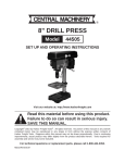
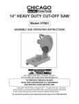
34 inch floor radial
drill press
Model 44846
assembly and Operating Instructions
Visit our website at: http://www.harborfreight.com
Read this material before using this product.
Failure to do so can result in serious injury.
Save this manual.
Copyright© 2000 by Harbor Freight Tools®. All rights reserved. No portion of this manual or any artwork contained herein may be reproduced in any shape or form without the express written consent of Harbor Freight
Tools. Diagrams within this manual may not be drawn proportionally. Due to continuing improvements, actual
product may differ slightly from the product described herein. Tools required for assembly and service may not
be included.
For technical questions or replacement parts, please call 1-800-444-3353.
Revised Manual 10b
Specifications
ITEM
DESCRIPTION
Motor
120 VAC, 60 Hz, single phase, 1/3 HP, 1700
RPM, 3 amps
Spindle Speeds
620, 110, 1720, 2340, 3100 RPM
Spindle Stroke
3 inches
Spindle Taper
MT2
Spindle to Base Distance
50-1/4 incles (maximum)
Spindle to Table Distance
28-1/4 inches
Column
3.12 (diameter) x 52-3/8 (H) inches
Head to Base
Base Dimensions
10-1/2 (W) x 17-3/4 (L) inches; Slot 1/2 (W)
x 5-1/2 (L) inches
Overall Dimensions
64-7/8 (H) x 33 (L) x 7-1/2 (W) inches
Chuck
Taper: JT-3; Size: 5/8”
Table Slot
5/8 (W) x 3 (L) inches
Table Rotation
360°; Tilt: 45° (left and right)
Head Tilts
0° -40° -90°
Radial Travel
12 inches
Table Size
11-7/8 (diameter) inches
Weight
135 lbs.
# 86PJ
E105017
Save This Manual
You will need the manual for the safety warnings and precautions, assembly instructions,
operating and maintenance procedures, parts list and diagram. Keep your invoice with this
manual. Write the invoice number on the inside of the front cover. Keep the manual and
invoice in a safe and dry place for future reference.
Safety Warnings and Precautions
WARNING: When using tool, basic safety precautions should always be followed to
reduce the risk of personal injury and damage to equipment.
Read all instructions before using this tool!
1.
Keep work area clean. Cluttered areas invite injuries.
2.
Observe work area conditions. Do not use machines or power tools in damp or wet
locations. Don’t expose to rain. Keep work area well lighted. Do not use electrically
powered tools in the presence of flammable gases or liquids.
3.
Keep children away. Children must never be allowed in the work area. Do not let
them handle machines, tools, or extension cords.
4.
Store idle equipment. When not in use, tools must be stored in a dry location to
inhibit rust. Always lock up tools and keep out of reach of children.
SKU 44846
Page 2
Rev 10b
5.
Do not force tool. It will do the job better and more safely at the rate for which it
was intended. Do not use inappropriate attachments in an attempt to exceed the tool
capacity.
6.
Use the right tool for the job. Do not attempt to force a small tool or attachment to
do the work of a larger industrial tool. There are certain applications for which this tool
was designed. Do not modify this tool and do not use this tool for a purpose for which
it was not intended.
7.
Dress properly. Do not wear loose clothing or jewelry as they can be caught in
moving parts. Protective, electrically non-conductive clothes and non-skid footwear
are recommended when working. Wear restrictive hair covering to contain long hair.
8.
Use eye and ear protection. Always wear ANSI approved impact safety goggles.
Wear a full face shield if you are producing metal filings or wood chips. Wear an ANSI
approved dust mask or respirator when working around metal, wood, and chemical
dusts and mists.
9.
Do not overreach. Keep proper footing and balance at all times. Do not reach over or
across running machines.
10. Maintain tools with care. Keep tools sharp and clean for better and safer
performance. Follow instructions for lubricating and changing accessories. Inspect tool
cords periodically and, if damaged, have them repaired by an authorized technician.
The handles must be kept clean, dry, and free from oil and grease at all times.
11. Disconnect power. Unplug when not in use.
12. Remove adjusting keys and wrenches. Check that keys and adjusting wrenches
are removed from the tool or machine work surface before plugging it in.
13. Avoid unintentional starting. Be sure the switch is in the Off position when not in
use and before plugging in.
14. Stay alert. Watch what you are doing, use common sense. Do not operate any tool
when you are tired.
15. Take caution as some woods contain preservatives such as copper chromium
arsenate (CCA) which can be toxic. When cutting these materials extra care should
be taken to avoid inhalation and minimize skin contact.
16. Check for damaged parts. Before using any tool, any part that appears damaged
should be carefully checked to determine that it will operate properly and perform its
intended function. Check for alignment and binding of moving parts; any broken parts
or mounting fixtures; and any other condition that may affect proper operation. Any
part that is damaged should be properly repaired or replaced by a qualified technician.
Do not use the tool if any switch does not turn On and Off properly.
17. Guard against electric shock. Prevent body contact with grounded surfaces such as
pipes, radiators, ranges, and refrigerator enclosures.
18. Replacement parts and accessories. When servicing, use only identical
SKU 44846
Page 3
replacement parts. Use of any other parts will void the warranty. Only use accessories
intended for use with this tool. Approved accessories are available from Harbor Freight
Tools.
19. Do not operate tool if under the influence of alcohol or drugs. Read warning
labels on prescriptions to determine if your judgment or reflexes are impaired while
taking drugs. If there is any doubt, do not operate the tool.
20. Use proper size and type extension cord. If an extension cord is required, it must
be of the proper size and type to supply the correct current to the tool without heating
up. Otherwise, the extension cord could melt and catch fire, or cause electrical
damage to the tool. This tool requires use of an extension cord of 0 to 12 amps
capability (up to 50 feet), with wire size rated at 16 AWG. Longer extension cords
require larger size wire (smaller AWG number). If you are using the tool outdoors, use
an extension cord rated for outdoor use. (Signified by “WA” on the jacket).
21. Secure Workpiece. Use clamps or a vise to hold workpiece, if possible. Never hold
workpiece with your hands.
22. Never leave Drill Press running unattended. Turn the power OFF.
23. Maintenance. For your safety, service and maintenance should be performed
regularly by a qualified technician.
Note: Performance of this tool may vary depending on variations in local line voltage. Extension cord usage may also affect tool performance.
Warning: The warnings, cautions, and instructions discussed in this instruction manual
cannot cover all possible conditions and situations that may occur. It must be understood by the operator that common sense and caution are factors which cannot be built
into this product, but must be supplied by the operator.
Drill Press Safety Warnings and Precautions
1.
Secure the Drill Press Base to the floor using 7/16 inch bolts (not supplied).
2.
Locate the Drill Press in an area where you walk around it unhampered.
3.
Avoid kickback and grabbing by clamping the workpiece to the table, or use a vise that
is secured to the table. If the workpiece begins to spin, do not attempt to stop it with
your hands. Turn the motor OFF, and wait until it stops spinning before attempting to
remove it.
4.
Avoid being caught and pulled into the spinning chuck. Do not wear gloves, long
sleeve shirts, ties, or jewelry. Long hair must be bundled behind the head.
5.
Never place hands and arms near the workpiece to avoid the possibility of the
workpiece coming loose and striking you.
6.
Before drilling, turn on the motor and check for bit wobble or machine vibration. If this
is found, correct the problem before drilling.
7.
Set the proper spindle speed for the specific drilling operation.
SKU 44846
Page 4
8.
When finished with the Drill Press, always press the Switch to the OFF position.
9.
Do not mount (or adjust) the workpiece on the Drill Press Table while the motor is
running.
10. When drilling or cutting large holes, use the slower speeds and securely fasten the
workpiece to the table using a mounted vise.
11. Do not use drill bits that extend more than six inches from the Chuck.
12. Do not use circle cutters, rotary planers, wire wheels, router bits, or shaper cutters on
this Drill Press.
Unpacking
When unpacking, check that all parts are included. Refer to the Parts Lists and Assembly
Drawings located at the end of this manual. If any parts are missing or broken, please call
Harbor Freight Tools at the number on the cover of this manual as soon as possible.
Assembly
Assembly hardware is located in one box and one bag. Each contains the necessary parts
for each assembly step. Remove all packing and protective material from the Drill Press
components. To aid in assembly, refer to the Assembly Drawings at the end of this manual.
1.
Position the Base (B6) on a level and sturdy floor for mounting.
Bolt the Base to the floor using appropriate hardware (not supplied). Base holes will
accommodate 7/16 inch bolts. Pull out the Wire Stabilizer (B21) rod from the rear of
the Base.
2.
Place the Column Support (B4) on the Base, aligning the mounting holes.
3.
Insert four large Hex Screws (B5) into the mounting holes and tighten with a wrench.
4.
Insert the Column (B1) into the Column Support (B4) and secure with Screw (B3).
Feed Knob (34)
Belt Guard (A25)
Switch (2)
Motor (22)
Clamping Lever (30), Right
Chuck (A12)
Moving Bar (32)
Column Collar (B19)
Clamping Lever (30), Left
Table (B20)
Table Support (B7)
Crank (B8)
Column (B1)
Column Support (B4)
Wire Stabilizer (B21)
Base (B6)
SKU 44846
Page 5
5.
Install the Table Support (B7), with attached table Arm (B14), over the Column (B1)
and slide it down. Engage the gears onto the Rack (B2). Tighten the Table Clamp
(B13).
6.
Slide the Column Collar (B19) over and down the Column (B1) about 8 inches.
Tighten Screw (B11).
7.
Place the Extend Arm (B15) into the Arm (B14), and then the Table (B20) into the
opening in the Extend Arm.
CAUTION: Avoid injuries. The next step involves lifting the Head Assembly onto the
Column. The Head Assembly is heavy. Have someone help you lift this assembly into
place.
8.
Using two people, lift the Head Assembly and insert the Column Guide (18) over the
Column (B1).
Slide it down on the Column Tube as far as it will go. Align it so that it faces straight
forward, inline with the Base.
9.
Insert one Locking Shoe (15) into place inside the bottom of the Column Guide (18),
and the other on the outside of the Column Guide. Tighten the Clamping Lever (30)
into the Locking Shoe at the base of the Column Guide.
10. Adjust V-Belt (A1) tension or change speeds.
- Open the Belt Guard (A25) to expose the V-Belt.
- Loosen the Thumb Nut (28) to relieve the V-Belt tension.
- If necessary, move the Belt up or down on the pulleys to change the drill speed.
- Push the Motor backward, tightening the Belt on the pulleys, and hold in place.
- Turn the Thumb Nut (28) clockwise to tighten the V-Belt in place.
- Refer to the chart inside the Guard lid to select speed and belt locations.
Note: To test the proper belt tension, push in on the center of each belt at its center. It should
move only 1/2 inch (in or out).
Caution: overtightening the belts can cause the motor to bind, and not start. It can also
damage Motor bearings.
11. Locate the Feed Knobs (34) and Feed Rods (35) and screw into the Hub (36).
12. Install the Chuck (A12).
- Thoroughly clean the tapered hole in the Chuck and the Spindle (A15) shaft of all
dirt, grease, oil, and protective coatings (paint thinner may be necessary).
- Slide the Chuck onto the Spindle shaft.
- Turn the Chuck sleeve clockwise and open the jaws completely.
- Tap the nose of the Chuck lightly with a piece of wood to securely set the Chuck.
13. Verify that the Table (B20) is square (90 degrees) to the Head
Assembly and drill bit.
- Raise the Table to within four inches of the Chuck.
- Place the long side of a combination square on the Table.
- Align the short side of the square to the drill bit.
- If the Table is not square to the bit, loosen Hex Bolt (B12) with
SKU 44846
Page 6
Hex Bolt
(B12)
a wrench.
- Rotate the Table until it is square to the bit.
- Retighten the Hex Bolt (B12).
Operation
Warning: Avoid personal injuries. Before operating this machine, review all Safety Warnings and Precautions listed on pages 2 through 5.
Drilling
While following these procedures, refer to the photo on page 5.
1.
Loosen the Table Clamp (B13) and turn Crank (B8) to adjust the Table height to
accommodate the workpiece being drilled. Retighten Table Clamp.
2.
Open the Chuck (A12) and insert the drill bit in the center. Tighten with the Chuck Key.
3.
Secure the workpiece (and backup material) to the Table using a vise and/or clamp.
The workpiece sits on the backup material which in typically a scrap piece of wood
used to stabilize the workpiece. It also helps the drill make a cleaner hole. To keep it
from spinning, have it touching the left side of the Column.
4.
Bring the drill bit down with the Feed Knob (34) to where the hole is to be drilled.
Make minor workpiece alignment adjustments.
5.
Plug the Power Cord (29) into an electrical outlet.
Warning: Wear an ANSI approved, full face shield while drilling any type of material.
6.
Push the Switch (2) up to turn the Motor ON.
7.
Pull down on the Feed Knob and slowly drill the hole into the workpiece.
Warning: If the drill bit grabs and spins the workpiece, do not attempt to stop the spinning with your hands. Step back, and push the Switch down to the OFF position. Wait
for the spindle to stop turning before dislodging the workpiece.
8.
When the drilling is complete, press the Switch to the OFF position.
Adjusting the Head Angle
Caution: Before making any adjustments, unplug the Power Cord (29) from the electrical outlet.
1.
To adjust the Head angle to other than 90 degrees, loosen the right Clamping Lever
(B30).
2.
Pull out the Guide Pin (16) and turn it 90 degrees so that it’s cross pin rests on top of
the outlet.
3.
Align the mark on the Column Guide (18) with the Scale (33).
4.
Once the Head is tilted to the desired angle, retighten the Clamping Lever.
SKU 44846
Page 7
5.
To return the Head to the 90 degree position, do these procedures in reverse.
Moving the Head Horizontally
1.
Loosen the left-side Clamping Lever (30) and rotate the Head Assembly up to 360
degrees.
2.
Retighten the Clamping Lever.
Moving the Head Forward or Backward.
1.
Loosen the right-side Clamping Lever (30).
2.
Turn the Moving Bar (32) clockwise or counterclockwise until the desired position is
reached.
3.
Tighten the right-side Clamping Lever.
Adjusting the Table
1.
Loosen the Support Clamp (B16).
2.
Turn the Crank (B8) to move the Table to the desired height.
3.
Tighten the Support Clamp.
4.
To tilt the Table, loosen Hex Bolt (B12) and turn the Table.
The scale can be used to approximate the angle. Tighten the Hex Bolt.
Setting the Depth Scale to Drill to a Specified Depth
Depth Lock Screw (38)
1.
Secure the workpiece to the Table.
2.
Mark the desired hole depth on the side of the workpiece.
Also view the depth indicator on the Depth Stop Ring (37).
3.
Loosen the Depth Lock Screw (38).
4.
Turn the scale on the Depth Stop Ring to the desired depth and
retighten the Depth Lock Screw.
5.
Turn the Drill Press ON and pull the Feed Knob (34)
counterclockwise until it drills the hole and stops at the set depth.
6.
Turn the Drill Press OFF.
Changing the Chuck Speed
The Drill Press has five different Chuck speeds. Refer to the speed chart in the Belt Guard
(A25).
1.
Lift the Belt Guard lid.
2.
Loosen the Thumb Nut (28). The belt tension should release.
3.
Move the V-belt (A1) to the desired level (speed) on the pulleys.
SKU 44846
Page 8
4.
Push the Motor (22) backward and hold. Retighten the Thumb Nut.
Note: To test the proper belt tension, push in on the center of each belt at its center. It should
move only 1/2 inch (in or out).
5.
Close the Belt Guard Lid.
Maintenance
Warning: Before performing any maintenance to this machine, remove the line cord
from the electrical outlet.
Removing the Chuck and Spindle Shaft
During this procedure, refer to the Chuck and Spindle Assembly Drawing.
1.
Pull the Feed Knob counterclockwise and hold the Chuck at a depth of three inches.
2.
Align the key holes in the Spindle (A15) shaft and the Quill Tube (A10) by turning the
Chuck by hand.
3.
Insert a Wedge Drift Key (not supplied) into the key holes.
4.
Lightly tap the wedge Drift Key (A14) with a rubber mallet until the Spindle shaft falls
out of the Quill Tube.
Place a bundled cloth or basket below the Chuck to catch it when it falls.
Installing the Chuck and Spindle Shaft
1.
Using a clean cloth, wipe the tapered surfaces on the Spindle shaft (A15).
2.
Slide the Spindle shaft and Chuck assembly up and into the Quill Tube (A10).
At the same time, turn the assembly until the rectangular end of the Spindle shaft slips
into the notch on the Quill Tube.
Warning: In the previous step, if the Spindle shaft is not properly set in the Quill Tube
notch, it may fly out during operation.
3.
Loosen the Support Clamp (B16) and raise the Table (B20) about three inches below
the Chuck.
4.
Turn the Chuck sleeve clockwise to open the jaws completely.
5.
Pull the Feed Knob counterclockwise and force the Chuck against the Table until the
Spindle shaft is secure.
Adjusting the Feed Wheel Return Tension Spring
Caution: Wear a full face shield during this procedure.
1.
Move the Chuck to its uppermost position and lock in place.
2.
Insert a screwdriver in the lower-front notch of the Cap Spring (8).
Hold it in place and, using a wrench, remove the (outer) Hex Nut (7) only.
SKU 44846
Page 9
3.
With the screwdriver still in place, loosen the (inner) Hex Nut (7) until the Cap Spring
notch disengages from the Spring Retainer (10) -- about 1/8 inch.
4.
Turn the screwdriver counterclockwise and engage the next Cap Spring notch.
Leave the screwdriver in place.
5.
Tighten the (inner) Hex Nut just enough to engage the
notch.
If this Hex Nut is too tight, it will restrict (up and down)
Chuck-Spindle movement.
6.
Pull the Feed Knob and check the spring tension,
making sure the up movement is smooth and
complete.
From one inch down, the Chuck should return to its
uppermost position. If more tension is required, repeat
steps.
Cap Spring (8)
Hex Nut (7)
Guide Pin (16)
Clamping Lever
(30), Left
7.
Replace the (outer) Hex Nut (7) and tighten on top of
the (inner) Hex Nut. Do not overtighten.
8.
If the (up/down) movement is restricted, slightly loosen the (inner) Hex Nut, and
retighten the (outer) Hex Nut.
General Maintenance
1.
Using compressed air, blow clean the Table, Base, and Motor cooling vents of dirt and
materials.
2.
Apply paste wax to the Table and Column to enable movement and to help keep
surfaces clean.
3.
All bearings are factory lubricated and need no further attention.
4.
Periodically, lubricate the Tube Column, Table, and Spindle upper teeth with a light oil.
5.
Monthly, check the tightness of all mounting screws and bolts in the Base, Column,
and Head assemblies.
6.
Check belt for wear and replace if frayed or damaged in any way.
7.
Lubricate Spindle assembly with a light oil, weekly.
8.
Store in a clean and dry location.
SKU 44846
Page 10
Troubleshooting
syMptoM
possible cause
solution
- Incorrect spindle speed
- Dull drill bit
- Drilling too slowly
- Lacking lubrication
- Belt tension set wrong
- Spindle dry
- Loose spindle pulley
- Loose motor pulley
- Bent bit
- Worn Spindle Bearings
- Drill bit not in Chuck correctly
- Chuck not properly installed
- Change spindle speed
- Replace with new bit
- Drill faster
- Lubricate cutting area
- Adjust belt tension
- Lubricate spindle
- Check pulley nut
- Tighten Set screws
- Replace drill bit
- Replace spindle bearings
- Reinstall drill bit
- Reinstall Chuck and Arbor assembly
Feed Wheel
returns slowly, or
too fast
- Tension Spring not in
adjustment
- Adjust Tension Spring. See page 9.
Drill bit binds
- Workpiece pinching drill bit
- Dull drill bit
- Feed pressure too hard
- Belts loose
-
Drill bit burns or
smokes
Makes unusual
noise
Drill bit wobbles
Reposition workpiece, lubricate drill
Replace drill bit
Pull Feed Handle slowly.
Adjust motor and spindle belt tension
NOTE: Some parts are listed in these Part Lists are shown for illustration purposes only
and are not available individually as replacement parts.
PLEASE READ THE FOLLOWING CAREFULLY
THE MANUFACTURER AND/OR DISTRIBUTOR HAS PROVIDED THE PARTS DIAGRAM IN THIS
MANUAL AS A REFERENCE TOOL ONLY. NEITHER THE MANUFACTURER NOR DISTRIBUTOR MAKES ANY REPRESENTATION OR WARRANTY OF ANY KIND TO THE BUYER THAT
HE OR SHE IS QUALIFIED TO MAKE ANY REPAIRS TO THE PRODUCT OR THAT HE OR SHE
IS QUALIFIED TO REPLACE ANY PARTS OF THE PRODUCT. IN FACT, THE MANUFACTURER
AND/OR DISTRIBUTOR EXPRESSLY STATES THAT ALL REPAIRS AND PARTS REPLACEMENTS
SHOULD BE UNDERTAKEN BY CERTIFIED AND LICENSED TECHNICIANS AND NOT BY THE
BUYER. THE BUYER ASSUMES ALL RISK AND LIABILITY ARISING OUT OF HIS OR HER
REPAIRS TO THE ORIGINAL PRODUCT OR REPLACEMENT PARTS THERETO, OR ARISING
OUT OF HIS OR HER INSTALLATION OF REPLACEMENT PARTS THERETO.
SKU 44846
Page 11
Head Assembly Parts List
item #
item #
description
description
1
Self-tapping Screw, 4.2
21
Motor Mount
2
No-Volt Switch
22
Motor
3
Screw, Pan Hd., M5x12
23
Nut, Hex, M8
4
Switch Box
24
Washer, 8
5
Screw Set, Special
25
Cord, Motor
6
Nut, Hex
26
Washer, 8
7
Nut, Hex, M12
27
Screw, Hex, M8x20
8
Cap Spring
28
Nut, Thumb
9
Spring, Torsion
29
Cord, Power
10
Retainer Spring
30
Clamping Lever
11
Seat Spring
31
Horizontal Rack
12
Roll Pin
32
Moving Bar
13
Screw, Socket Hd.
33
Scale
14
Head
34
Feed Knob
15
Locking Shoe
35
Feed Rod
16
Guide Pin
36
Hub
17
Retaining Ring
37
Ring, Depth Stop
18
Column Guide
38
Depth Lock Screw
19
Horizontal Tube
39
Pin Stop
20
Cover Mount
Head Assembly Drawing
SKU 44846
Page 12
Pulley and Spindle Assembly Parts List
item #
description
item #
description
A1
V-belt, M58
A14
Drift Key
A2
Pulley Nut
A15
Spindle
A3
Spindle Pulley
A16
Ball Bearing, 60204
A4
Insert Pulley
A17
Knob
A5
Retaining Ring
A18
Screw, M5x12
A6
Locking Ring
A19
Screw, M5x12
A7
Washer
A20
Clamp Cord
A8
Ball Bearing, 60203
A21
Screw, M6x12
A9
Washer, Rubber
A23
Motor Pulley
A10
Quill Tube
A24
Screw, M6x10
A11
Chuck Key
A25
Belt Guard
A12
Chuck
A26
Form Washer
A13
Arbor
Pulley and Spindle Assembly Drawing
When ordering a part from this drawing, add an “A” prefix to the part number.
SKU 44846
Page 13
Base and Table Assembly Parts List
item #
description
B1
Column
B2
Rack
B3
Screw, M10x12
B4
Column Support
B5
Hex Bolt, M10x40
B6
Base
B7
Table Support
B8
Crank
B10
Pin Gear
B11
Screw, M6x10
B12
Hex Bolt, M16x35
B13
Table Clamp
B14
Arm
B15
Extend Arm
B16
Support Clamp
B17
Gear, Helical
B18
Worm, Elevation
B19
Column Collar
B20
Table
B21
Wire Stabilizer
Base and Table Assembly Drawing
When ordering a part from this drawing,
add an “B” prefix to the part number.
SKU 44846
Page 14
Limited 1 year / 90 Day warranty
Harbor Freight Tools Co. makes every effort to assure that its products meet high quality and durability standards, and warrants to the original purchaser that for a period of ninety
days from date of purchase that the engine/motor, the belts (if so equipped), and the blades
(if so equipped) are free of defects in materials and workmanship. Harbor Freight Tools also
warrants to the original purchaser, for a period of one year from date of purchase, that all other
parts and components of the product are free from defects in materials and workmanship (90
days if used by a professional contractor or if used as rental equipment). This warranty does
not apply to damage due directly or indirectly, to misuse, abuse, negligence or accidents,
repairs or alterations outside our facilities, normal wear and tear, or to lack of maintenance.
We shall in no event be liable for death, injuries to persons or property, or for incidental, contingent, special or consequential damages arising from the use of our product. Some states
do not allow the exclusion or limitation of incidental or consequential damages, so the above
limitation of exclusion may not apply to you. This warranty is expressly in lieu of
all other warranties, express or implied, including the warranties of
merchantability and fitness.
To take advantage of this warranty, the product or part must be returned to us with
transportation charges prepaid. Proof of purchase date and an explanation of the complaint
must accompany the merchandise. If our inspection verifies the defect, we will either repair or
replace the product at our election or we may elect to refund the purchase price if we cannot
readily and quickly provide you with a replacement. We will return repaired products at our
expense, but if we determine there is no defect, or that the defect resulted from causes not
within the scope of our warranty, then you must bear the cost of returning the product.
This warranty gives you specific legal rights and you may also have other rights which
vary from state to state.
3491 Mission Oaks Blvd. • PO Box 6009 • Camarillo, CA 93011 • (800) 444-3353
REV 10a
SKU 44846
Page 15