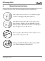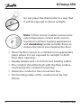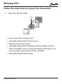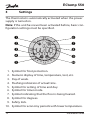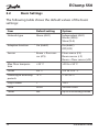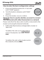
1
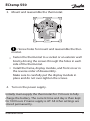
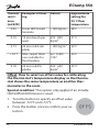
MAKING MODERN LIVING POSSIBLE Installation Guide ECtemp 550 Electronic Intelligent Thermostat www.EH.danfoss.com Danfoss A/S is not liable or bound by warranty if these instructions are not adhered to during installation or service. The English language is used for the original instructions. Other languages are a translation of the original instructions. (Directive 2006/42/EC) © 2012 Copyright Danfoss A/S ECtemp 550 Table of Contents 1 Introduction . . . . . . . . . . . . . . . 1.1 Technical Specifications . . . . . 1.2 Safety Instructions . . . . . . . . 3 4 6 2 Mounting Instructions . . . . . . . . . 7 3 Settings . . . . . . . . . . . . . . . . . 3.1 Time and Day of Week Settings 3.2 Basic Settings . . . . . . . . . . . 12 13 14 4 Warranty 21 5 Disposal Instruction 1 Introduction . . . . . . . . . . . . . . . . . . . . . . . . . . . 21 The ECtemp 550 thermostat controls electrical floor heating elements using a built-in and/or an external temperature sensor. The thermostat can be optimised for the room within a few days after the installation by continuously collecting updated temperature data. This will enable the unit to compensate for sudden temperature changes and makes it possible to achieve the selected temperature at the right time. Furthermore, the unit is able to automatically lower or raise the temperature at specific points of time, i.e. automatically switch between comfort and economy temperature. Installation Guide 3 ECtemp 550 Note: This thermostat does not apply to tariff control or similar systems. More information on this product can also be found at: ectemp.danfoss.com 1.1 4 Technical Specifications Operation voltage 220-240 V~, 50/60 Hz Standby power consumption <500mW Relay: Resistive load Inductive load Max. 16A / 3680W @ 230V cos φ= 0.3 Max. 1A Sensing units NTC 15 kOhm at 25°C Sensing values: 0°C 25°C 50°C 42kOhm 15kOhm 6kOhm Hysteresis ± 0.2°C with room sensor ± 0.4°C with floor sensor only Ambient temperature 0 to +30°C Floor temperature limit +20 to +50°C Frost protection temp. 5°C - Installation Guide ECtemp 550 Temperature range +5 to +35°C (room) or +5 to +50 (floor) Lowering in economy periods 0 to -30°C Offset (temp. correction) -5,5 to +5,5°C Cable specification max. 1x4mm2 or 2x2,5mm2 Ball pressure temperature 75°C Pollution degree Degree 2 (domestic use) Type Type 1C Software class Class A Storage temperature -20°C to +65°C Battery back-up 100 hours IP class 30 Protection class Class II - Weight 110g Dimensions 85 x 85 x 55mm (in-wall depth: 24mm) The product complies with the EN/IEC Standard "Automatic electrical controls for household and similar use": ▪ EN/IEC 60730-1 (general) ▪ EN/IEC 60730-2-7 (timer) ▪ EN/IEC 60730-2-9 (thermostat) Installation Guide 5 ECtemp 550 1.2 Safety Instructions Make sure the mains supply to the thermostat is turned off before installation. If the thermostat is installed in a network, the mains supply to all thermostats in the network must be off. IMPORTANT: When the thermostat is used to control a floor heating element in connection with a wooden floor or similar material, always use a floor sensor and never set the maximum floor temperature to more than 35°C. Please also note the following: ▪ The installation of the thermostat must be done by an authorized and qualified installer according to local regulations. ▪ The thermostat must be connected to a power supply via an all-pole disconnection switch. ▪ The sensor is to be considered as live voltage. Have this in mind if the sensor must be extended. ▪ Always connect the thermostat to continuous power supply. ▪ Do not expose the thermostat to moisture, water, dust, and excessive heat. 6 Installation Guide ECtemp 550 2 Mounting Instructions Please observe the following placement guidelines: Place the thermostat at a suitable height on the wall (typically 80-170cm.). The thermostat should not be placed in wet rooms. Place it in an adjacent room. Always place the thermostat according to local regulation on IP classes. Do not place the thermostat on the inner side of an exterior wall. Always install the thermostat at least 50 cm. from windows and doors. Installation Guide 7 ECtemp 550 Do not place the thermostat in a way that it will be exposed to direct sunlight. Note: A floor sensor enables a more accurate temperature control and is recommended in all floor heating applications and mandatory under wooden floors to reduce the risk of over-heating the floor. ▪ Place the floor sensor in a conduit in an appropriate place where it is not exposed to sunlight or draft from door openings. ▪ Equally distant and >2cm from two heating cables. ▪ The conduit should be flush with the floor surface countersink the conduit if necessary. ▪ Route the conduit to the connection box. ▪ The bending radius of the conduit must be min 50mm. 8 Installation Guide ECtemp 550 Follow the steps below to mount the thermostat: 1. Open the thermostat: Push down the release tab. Carefully detach the front cover. Remove the two screws. Carefully detach the display module. Make sure to pull it straight out to avoid damaging the 8-pin connector plug on the back of the module. ▪ Carefully detach the frame. ▪ ▪ ▪ ▪ Installation Guide 9 ECtemp 550 2. Connect the thermostat according to the connection diagram. IP30 0T30 D550 Max.Load Mains 16 (1) A 220-240V~ L N LOAD LOAD N L devinet Sensor NTC The screen of the heating cable must be connected to the earth conductor of the power supply cable by using a separate connector. The devinet terminals are used when connecting thermostats in a network. Network cables must be of identical isolation value as normal installation cables and have a recommendable specification of 2x1,5mm2 and a total length of maximum 100m. Note: Always install the floor sensor in a conduit in the floor. 10 Installation Guide ECtemp 550 3. Mount and reassemble the thermostat. = Screw holes for mount and reassemble the thermostat. ▪ Fasten the thermostat to a socket or an exterior wall box by driving the screws through the holes in each side of the thermostat. ▪ Install the frame, display module, and front cover in the reverse order of disassembly. Make sure to carefully put the display module in place and do not over-tighten the screws. 4. Turn on the power supply. Initially main supply the thermostat for 15 hours to fully charge the battery. The current time and day is then kept for 100 hours if mains supply is off. All other settings are stored permanently. Installation Guide 11 ECtemp 550 3 Settings The thermostat is automatically activated when the power supply is turned on. Note: If the unit has never been activated before, basic configuration settings must be specified. 1. 2. 3. 4. 5. 6. 7. 8. 9. 10. 12 Symbol for frost protection. Numeric display of time, temperature, text, etc. Day of week. Flashing indication of actual time. Symbol for setting of time and day. Symbol for timer mode. Symbol indicating that the floor is being heated. Symbol for degrees. Safety lock. Symbol for economy periods with lower temperature. Installation Guide ECtemp 550 3.1 Time and Day of Week Settings 1. Press and hold the button for 3 seconds. The clock symbol appears on the display and the day of the week is shown as a number (from 1-7) just below the time. You change the day of week by turning the button in either direction and the time passes 00:00. 2. Find and set the correct day and time. A black dot will appear on the outer ring at the same time. 3. Press the button once to confirm. Installation Guide 13 ECtemp 550 3.2 Basic Settings The following table shows the default values of the basic settings: Item Default setting Options Network type Alone (ALO) Independent (ALO) Master (MAS) Slave (SLA) Adaptive function On (AdAP) On (AdAP) Off (OFF) Sensor Room + floor sensor (rFS) Floor sensor (FS) Room sensor (r S) Room + floor sensor (rFS) Max. floor temperature +35 °C +20 to +50 °C Offset 0.0 °C -5.5 to +5.5 °C Lowering in economy periods -5 °C -1 to -30 °C Day of week 1 1 to 7 Time 00.00 24 hour clock Timer Set Up to 336 settings/week 14 Installation Guide ECtemp 550 How to enter the basic configuration settings 1. Press and hold the button for 12 seconds until “COdE” appears. 2. Turn the button clockwise until “0044” appears. 3. Press the button once to confirm. Network: How to specify whether you want to connect this thermostat with other thermostats in a network Please note that the slave units must be connected to the master unit using the devinet terminals. 1. Define the thermostat as independent, master or slave unit. To define this unit as an independent unit or if network is not used, choose ALO. To define this unit as the master unit in the network, choose MAS. Installation Guide 15 ECtemp 550 To define this unit as a slave unit in the network, choose SLA. Only one unit in the network can be defined as master unit. All slave units will respond to and send information to the master unit. Time, day of week and economy periods will be controlled from the master unit. All other settings must be specified for each slave unit. No more than 32 units can be combined in a network including independent units (even though these units do not communicate with the master unit). 2. Press the button once to confirm your selection. 16 Installation Guide ECtemp 550 Adaptive regulation: How to specify whether or not to optimise this thermostat for the room by timing heating start/stop 1. Turn the adaptive function on or off. To let the unit continuously collect updated room data, choose AdAP. This means improved performance (with compensation for e.g. sudden temperature drops in the room) and precise timing so the selected temperature is achieved at the desired time. To turn off the adaptive function, choose OFF This means that the heating will not start/stop until the specified time. 2. Press the button once to confirm your selection. Installation Guide 17 ECtemp 550 Sensor: How to specify whether an external floor sensor, the built-in room sensor or both is used to control the floor heating 1. Turn the button to choose one of the following sensor settings: If both a room sensor and a floor sensor is used, choose rFS. This option is suitable for all rooms but wet rooms. The thermostat must be installed in the same room as the floor sensor and the heating elements. If only a floor sensor is used, choose FS. The built-in room sensor is not used. This option is suitable for rooms in which a constant floor temperature is required, e.g. in a bathroom. If only a room sensor is used, choose r S. This option is not recommendable due to an increased risk of overheating the floor. The thermostat must be installed in the same room as the heating elements. 2. Press the button once to confirm your selection. 18 Installation Guide ECtemp 550 How to set the maximum floor temperature Special condition: This setting only applies if a floor sensor is used (the FS or rFS sensor option has been set). 1. Turn the button to change the temperature. 2. Press the button once to confirm your selection. Note: Please contact the floor supplier before changing the maximum floor temperature and be aware of the following: ▪ The floor temperature is measured where the sensor is placed. ▪ The temperature of the bottom of a wooden floor can be up to 10 degrees higher than the top. ▪ Floor manufactures often specify the max. temperature on the top surface of the floor. Installation Guide 19 ECtemp 550 Thermal Examples of floor- Details resisting ance [m2K/W] Approximate setting for 25˚C floor temperature 0.05 8 mm HDF based laminate > 800 kg/m3 28˚C 0.10 14 mm beech parquet 650 - 800 kg/m3 31˚C 0.13 22 mm solid oak plank > 800 kg/m3 32˚C < 0.17 Max. carpet thickness suitable for floor heating acc. to EN 1307 34˚C 22 mm solid fir planks 450 - 650 kg/m3 35°C 0.18 Offset: How to select an offset value for calibrating the thermostat’s temperature display so the thermostat shows the same temperature as another thermometer in the room Special condition: This option only applies if an installation with a room sensor is used. 1. Turn the button to specify an offset value between -5,5°C and +5,5°C. 2. Press the button once to confirm your selection. 20 Installation Guide ECtemp 550 Temperature decrease: How to specify how much the temperature is to be lowered during economy periods Note: If normal room heating is installed, we recommend lowering the temperature by no more than approx 5 °C. By default, the temperature decrease is set to -5 °C 1. Turn the button to set the setback level. For example, choose -4 °C to lower the temperature by 4 degrees. 2. Press the button once to confirm your selection. The display returns to normal. 4 Warranty 2 YEAR 5 Disposal Instruction Installation Guide 21 ECtemp 550 22 Installation Guide ECtemp 550 Danfoss A/S Electric Heating Systems Ulvehavevej 61 7100 Vejle Denmark Phone:+45 7488 8500 Fax: +45 7488 8501 Email: [email protected] www.EH.danfoss.com Danfoss can accept no responsibility for possible errors in catalogues, brochures and other printed material. Danfoss reserves the right to alter its products without notice. This also applies to products already on order provided that such alterations can be made without subsequential changes being necessary in specifications already agreed. All trademarks in this material are property of the respective companies. Danfoss Heating Solutions and the Danfoss Heating Solutions logotype are trademarks of Danfoss A/S. All rights reserved. 088L0358 & VISGF602 Produced by Danfoss Heating Solutions © 02/2012 Intelligent Timer Thermostat Floor / Room Sensor 220-240V~ 50-60Hz~ +5 to +35°C 16A/3680@230V~ IP 30 088L0044 ECtemp 550 ELKO 5 703466 209172 Designed in Denmark for Danfoss A/S DK EL 7224215263 SE EL 85 811 67 NO EL 5491495 FI SSTL 3531125 Product Documentation