1
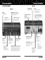
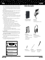
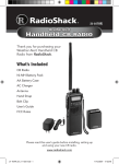
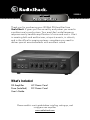
40-Watt 32-2054 PA Amplifier Thank you for purchasing your 40-Watt PA Amplifier from RadioShack. It gives you the versatility and power you need in a professional sound system. Your amplifier’s wide frequency response easily handles amplification of voice and music. Use it in meeting halls and auditoriums, at sports events, in schools, and in the office for paging systems—anywhere you need to deliver special announcements with excellent sound. What’s Included PA Amplifier Fuse (Installed) User’s Guide AC Power Cord DC Power Cord Please read this user’s guide before installing, setting up, and using your new amplifier. www.radioshack.com Quick Start Contents Contents Quick Start Quick Start .......................................................................................... 3 A Look at Your Amplifier..................................................................... 6 Follow these steps to quickly set up your PA Amplifier. For detailed operation instructions, see Pages 6-14. Front View........................................................................................................ 6 Rear View ......................................................................................................... 7 Preparation.......................................................................................... 8 Placing the Amplifier ...................................................................................... 8 Placing Speakers ............................................................................................. 8 Presetting the Controls................................................................................... 8 Presetting the Audio Input Sources......................................................... 8 Presetting the Amplifier............................................................................ 8 Tips for Speaker Connection ......................................................................... 9 Total Speaker Impedance......................................................................... 9 Proper Phasing .......................................................................................... 9 About Speaker Terminals ......................................................................... 9 Determining the Speaker Wire Length ................................................... 9 Connections ...................................................................................... 10 Connecting Speaker Wires to the Amplifier............................................... 10 Connecting One Speaker............................................................................. 10 Connecting Two Speakers in Series ............................................................ 11 Connecting Two Speakers in Parallel .......................................................... 11 Connecting Four Speakers in Series and Parallel Combination ............... 12 Connecting Speakers with Transformers .................................................... 13 Step 1 Connect optional components (microphones, tuners, turntables, CD players, tape decks, or extra AMPLIÞER TOEXPANDYOURSYSTEM AUX/CD Connect high-level sound sources, such as CD player, tape deck, or tuner. PHONO AUX/CD MIX BUS Use a shielded cable with phono plugs to connect to another MP-40 amplifier. PHONO Connect low-level sound sources, such as a turntable. Note: Set the PHONO AUX/CD switch to PHONO. Troubleshooting ................................................................................ 15 Specifications .................................................................................... 16 Care and Maintenance...................................................................... 16 Replacing the DC Power Cord’s Fuse ......................................................... 16 Safety ................................................................................................ 17 Do Stuff ............................................................................................. 19 Limited Warranty............................................................................... 20 MIC 1, MIC 2 Connect up to two microphones. Caution: Before connection, turn off your amplifier and components and set their volume controls to minimum. To prevent hum and other noise, use lowcapacitance shielded cables. 3TEP #ONNECTSPEAKERSTOYOURAMPLIÞER Connect your speakers together in series, in parallel, or in series and parallel combination. Then connect the speaker’s negative terminals to amplifier’s COM terminal, and their positive terminals to the amplifier’s 4, 8, 16, or 70V terminal. 2 3 Quick Start Quick Start 4) Adjust the following controls to the desired volume and balance: MIC 1, MIC 2, PHONO/AUX, 100Hz, 1kHz, and 8 kHz. 5) When you get the desired balance, adjust MASTER VOLUME to the desired level. Retaining Catch Press down the retaining catch of the correct terminal and insert the wire end into the terminal’s hole. Then, release the retaining catch to secure the wire. Power Indicator LEVEL Indicator (in dB) MASTER VOLUME To speaker’s positive terminal To speaker’s negative terminal 3TEP 0OWERYOURAMPLIÞER To use AC power, use the AC power cord to connect your amplifier’s AC IN jack to a standard wall outlet. To use DC power, use the DC power cord to connect your amplifier’s DC 12V IN jack to a vehicle’s 12V accessory socket. MIC 1 and MIC 2 Volume Controls POWER TONE CONTROL (100Hz, 1kHz, 8kHz) PHONO/AUX Volume Control Step 5 Monitor the sound source DC 12V IN AC IN Cautions: • Your vehicle must have a negative ground electrical system. If you are not sure of this, check with your vehicle dealer. • Disconnect the AC power cord before you connect the DC power cord. Likewise, disconnect the DC power cord before you connect the AC power cord. Insert the ¼” (6.35 mm) plug of either mono or stereo headphones (not supplied) to the PHONES jack. Headphones help easily check and adjust the balance of the sound sources. PHONES Jack 3TEP 5SEYOURAMPLIÞER 1) Turn on the POWER switch. The power indicator lights. 2) Start the input sound source. 3) Set MASTER VOLUME to about the middle position. The LEVEL Indicator ßASHESONFROMLEFTTORIGHTINDICATINGTHESOUNDLEVEL 4 5 A Look at Your Amplifier A Look at Your Amplifier Rear View A Look at Your Amplifier L/R PHONO Jacks Connect a turntable. Front View POWER Turn the amplifier on or off. PHONO/AUX Volume Control Adjust the volume of the turntable or auxiliary sound source. LEVEL Indicator (in dB) Monitors and controls the output power level. Power Indicator Lights when the amplifier is turned on. PHONES Jack Connect headphones to hear mixed audio in privacy. MIC 1 and MIC 2 Volume Controls Adjust the levels of the microphones separately. MIC 1 and MIC 2 Input Jacks Connect up to two dynamic microphones. MASTER VOLUME Adjust the overall sound level. TONE CONTROL (100Hz, 1kHz, 8kHz) Enhance the sound or tailor the high, medium, and low frequencies for each audio source input to the acoustics of a particular performance environment. 6 GND Connect a ground wire (black or green) to avoid low-frequency hum. Terminals (COM, 4, 8, 16, 70V) Connect speaker wires to the selected terminals. AC OUTLET (UNSWITCHED) Supply power (maximum load of 100W) to a musical instrument or another amplifier. PHONO AUX/CD Switch Select turntable or other audio input source. DC 12V IN Jack Power the amplifier from a 5A, 12V vehicle battery source. AUX/CD Input Jacks Connect a variety of audio input sources for music and special effects. MIX BUS Jack Connect an extra amplifier for multiple audio sources. 7 AC IN Connect to a standard AC outlet using the supplied AC power cord. Preparation Preparation Tips for Speaker Connection Preparation Placing the Amplifier Put your amplifier to a place with adequate ventilation. Do not put it on thick carpeting (which can restrict air flow) or near a heat source, such as a heat vent or radiator (which can cause overheating). Placing Speakers Speaker placement depends on your room’s size and arrangement. We recommend you play a wide-range recording and experiment with speaker placement until you find the locations that result in best sound. For best results, point the speakers toward the listeners, especially if you place the speakers far apart so their coverage areas overlap. This prevents dead spots (areas not covered by the speakers’ sound). Position the speakers slightly above the level of the listeners’ heads, and be sure you have determined the correct speaker impedance (see “Total Speaker Impedance” on Page 9). Presetting the Controls Before you begin making connections or using your amplifier, preset the audio input and amplifier controls to avoid overdriving a channel or producing extremely loud, unpleasant sound. You can connect one or more 4, 8, or 16 speakers (not supplied) to the amplifier, with or without transformers. To ensure equal volume from each speaker, all the speakers connected (in series or parallel) without line transformers should have the same impedance rating. Total Speaker Impedance Before you connect speakers to the amplifier, determine the speaker connection mode: in series, in parallel, or in series and parallel combination, then determine the total speaker impedance. For connections in series, the total impedance is the sum of the impedances of all the speakers connected. For example, if you connect three 4 speakers in series, the total speaker impedance is 12. For connections in parallel, the total impedance is the quotient of the impedance of one speaker divided by the number of speakers. For example, if you connect two 8 speakers in parallel, the total speaker impedance is 4. Important: If you connect more than two speakers in series only or in parallel only, be sure the total impedance does not exceed the amplifier’s maximum impedance (16) or fall below the minimum impedance (4). A total speaker impedance higher than 16 or lower than 4 can damage your amplifier. Presetting the Audio Input Sources Note: You can achieve a proper total speaker impedance with a combination of connections in series and in parallel. Set the audio input controls to these levels. Proper Phasing Audio Device Turntable Tape Deck CD Player Amplifier Receiver Control Power Power Power Power, Tone Setting Off Off Off Off, Flat Presetting the Amplifier After you turn on the amplifier or change the program source, set the controls to a comfortable listening level. Warning: To prevent possible hearing damage, set the amplifier’s controls to the levels below. Control Power MIC 1, MIC 2, PHONO/AUX 100 Hz, 1 kHz, 8 kHz MASTER VOLUME 8 Setting Off MIN 0 dB (mid-position) MIN Proper phasing is important when you use more than one speaker in the same room or area. Out-of-phase speakers can lose up to half of their potential volume, and can have a significantly decreased bass effect. Proper phasing occurs when speakers are set to allow sound to flow in the same direction. About Speaker Terminals Most speaker terminals are color-coded or have a symbol that indicates the terminal’s polarity: red (+) = positive; black (–) = negative. Phasing is correct when you connect this way: speaker’s negative terminal to amplifier’s COM terminal (–), speaker’s positive terminal to amplifier’s other terminals. Determining the Speaker Wire Length Use the shortest length of wire possible to connect the speakers. After placing the speakers in the desired locations, determine the wire length and choose the appropriate gauge size. • If wire length is 25 feet (7.6 meters) or less, wire gauge is 18. • If wire length is over 25 feet, wire gauge is 16. If you connect speakers without transformers, the speaker wire should be no longer than 50 feet (15.24 meters). 9 Connections Connections Connecting Two Speakers in Series Connections Connecting Speaker Wires to the Amplifier 1. Use a wire stripper (not supplied) to remove about half inch of the insulation from the end of the speaker wire. 2. Using a wire connector (not supplied), twist the exposed wire to secure all the wire strands. Remove the wire connector for step 3. 3. Press and hold the retaining catch of the correct terminal on the amplifier and insert the wire into the terminal’s hole. Release the retaining catch to secure the wire. • Connect the two speakers together, Speaker A’s positive terminal to Speaker B’s negative terminal. • Connect Speaker A’s negative terminal to the amplifier’s COM terminal. • Connect Speaker B’s positive terminal to the amplifier’s 4, 8, or 16 terminal. Amplifier Terminals Wire Connector Retaining Catch Speaker A Speaker B Connecting Two Speakers in Parallel Connecting One Speaker Connect the speaker’s negative (–) terminal to the amplifier’s COM terminal, and the speaker’s positive (+) terminal to the amplifier’s 4, 8, or 16 terminal. • Connect the negative terminals of the two speakers together, and then connect both wires to the amplifier’s COM terminal. • Connect the positive terminals of the two speakers together, and then connect both wires to the amplifier’s 4, 8, or 16 terminal. Speaker A Amplifier Terminals Amplifier Terminals Speaker Terminals 10 Speaker B 11 Connections Connections Connecting Four Speakers in Series and Parallel Combination Connecting Speakers with Transformers 1. Group the four speakers into two pairs (A and B, C and D). Connect each pair of speakers in series: A’s positive terminal to B’s negative terminal, C’s negative terminal to D’s positive terminal. If you use all 8 speakers, the total impedance of a pair is 16. 2. Connect the two pairs together in parallel: A’s negative terminal to D’s negative terminal, B’s positive terminal to C’s positive terminal. If you use all 8 speakers, the total impedance of the four speakers thus connected is 8 ((8+8)/2=8). 3. Connect the negative terminals of Speakers A and D to the amplifier’s COM terminal, and the positive terminals of Speakers B and C to the amplifier’s 4, 8, or 16 terminal. For best results when using two or more speakers, connect a line transformer (not included) to each speaker. Transformers allow you to: • Connect speakers with different impedances without causing output differences between the speakers. • Add or remove a speaker from the PA system without having to recalculate the entire system’s impedance. • Reduce signal loss when using a speaker wire over 50 feet (15.24 meters) long. Line transformers have primary connection taps on the input side, which are rated in watts, and secondary connection taps on the output side, which are rated in ohms. Before you connect speakers, be sure the total wattage of the primary taps you use does not exceed the amplifier’s maximum output power rating (40W). Amplifier Terminals Speaker A Speaker D Speaker B Speaker C The following illustration shows how to connect three speakers with transformers. • Connect the amplifier’s 70V terminal to the primary taps (10, 5, 2.5, 1.25, or 0.62 watts) of the transformer. • Connect the amplifier’s COM terminal to the C (common) taps on the Input Side of the transformer. • Connect the speaker’s positive terminal to the transformer’s 4, 8, or 16 tap (whichever matches the total speaker impedance). • Connect the speaker’s negative terminal to the C tap on the Output Side of the transformer. Notes: • Do not connect multiple wires to the amplifier’s 70V and COM terminals. • Wires with the mark A are to be connected together. • Usually, a speaker in a system uses the same wattage tap of its transformer. If you want a particular speaker to have a higher volume level, connect the wire from the amplifier’s 70V terminal to a higher wattage tap on the transformer. Illustration on Page 14 12 13 Troubleshooting Connections Troubleshooting Transformer Input Side ide Output S Problem No power No sound 8, 2.5W Speaker A A A Transformer Input Side Transformer ide Output S Input Side ide Output S Feedback 8, 5W Speaker Solution Sound sources or speakers are not properly connected. Sound sources or speakers are not properly connected. Check all connections. A microphone or cable might be faulty or loose. Check all microphones and cables. The speaker’s wires might be of the wrong impedance. Make sure all speakers connected have the same impedance rating. The speaker’s wires might be too small. Make sure the speaker’s wires are the correct gauge according to their lengths. The amplifier might have shut down. Turn off the amplifier and let it cool down. Make sure the amplifier is properly ventilated, and then turn it back on. Microphones or speakers are too close together. Reposition the microphones and speakers. 16, 1.25W Speaker 14 Check all connections. Adjust the volume controls to The MASTER VOLUME, MIC 1, MIC 2, PHONO/AUX, desired settings. 100 Hz, 1 kHz, 8 kHz controls are set to minimum. Amplifier A Cause 15 Safety Specifications Specifications Important Safety Instructions Output Power (at THD 10%, 4 Load 1kHz)..................................................40W Total Harmonic Distortion (at 5 Watts, 4, 1kHz, with Band Pass Filter) MIC ......................................................................................................... 0.50% AUX ......................................................................................................... 0.10% PHONO .................................................................................................. 0.30% Input Sensitivity (at 10%, THD, 1kHz) MIC ........................................................................................................2.5 mV AUX .......................................................................................................150 mV PHONO .................................................................................................3.5 mV Signal to Noise Ratio with A-WTD MIC ..........................................................................................................60 dB AUX ..........................................................................................................80 dB PHONO ...................................................................................................70 dB Hum and Noise at 4 At MASTER VOLUME MIN......................................................................1 mV At MASTER VOLUME MAX ..................................................................50 mV Power Supply ..............................................................120V AC, 60Hz; or 12V DC Dimensions (W×D×H) .......................... 12.8 × 8.9 × 3.3 in (324 × 226 × 85 mm) 1. 2. 3. 4. 5. 6. 7. 8. 9. 10. 11. 12. Specifications are subject to change and improvement without notice. Actual product may vary from the images found in this document. Care and Maintenance • • • • Keep the amplifier dry; if it gets wet, wipe it dry immediately. Use and store the amplifier only in normal temperature environments. Handle the amplifier carefully; do not drop it. Keep the amplifier away from dust and dirt, and wipe it with a damp cloth occasionally to keep it looking new. • Modifying or tampering with the amplifier’s internal components can cause a malfunction and might invalidate its warranty. If your amplifier is not performing as it should, take it to your local RadioShack store for assistance. 13. 14. 15. Replacing the DC Power Cord’s Fuse If the amplifier does not operate from a 12V battery source, check the fuse in the DC power cord plug. If the fuse is blown, remove the cap of the plug and replace the fuse with one of the proper type and rating (6A, 250V). 16 16. Read these instructions. Keep these instructions. Heed all warnings. Follow all instructions. Unplug this product from the wall outlet before cleaning. Do not use liquid cleaners or aerosol cleaners. Clean only with dry cloth. Only use attachments/accessories specified by the manufacturer. Do not use this product near water. Use only with the cart, stand, tripod, bracket, or table specified by the manufacturer or sold with the apparatus. When a cart is used, use caution when moving the cart/apparatus combination to avoid injury from tip-over. Exercise caution when moving any product and cart combination. Quick stops, excessive force, and uneven surfaces may cause the appliance and cart combination to overturn. Slots and openings in the cabinet are provided for ventilation and to ensure reliable operation of the product and to protect it from overheating. Do not block any ventilation openings. Install in accordance with the manufacturer’s instructions. Use only the type of power source indicated on the label. If you are not sure of the type of power supply to your home, consult your product dealer or local power company. For products intended to operate on battery power, or other sources, refer to the operating instructions. Do not defeat the safety purpose of the polarized or grounding-type plug. A polarized plug has two blades with one wider than the other. A grounding type plug has two blades and a third grounding prong. The wide blade or the third prong are provided for your safety. If the provided plug does not fit into your outlet, consult an electrician for replacement of the obsolete outlet. Alternate Warnings: This product is equipped with a three-wire grounding-type plug, a plug having a third (grounding) pin. This plug will only fit into a groundingtype power outlet. This is a safety feature. If your are unable to insert the plug into the outlet, contact your electrician to replace your obsolete outlet. Do not defeat the safety purpose of the grounding-type plug. Protect the power cord from being walked on or pinched particularly at plugs, convenience receptacles, and the point where they exit from the apparatus. Protective Attachment Plug: The product is equipped with an attachment plug having overload protection. This is a safety feature. See Instruction Manual for replacement or resetting of protective device. If replacement of the plug is required, be sure the service technician has used a replacement plug specified by the manufacturer that has the same overload protection as the original plug. If an outside antenna is connected to the receiver, be sure the antenna system is grounded so as to provide some protection against voltage surges and built-up static charges. Article 810 of the National Electrical Code, ANSI/NFPA 70, provides information with regard to proper grounding of the mast and supporting structure, grounding of the mast and supporting structure, grounding of the lead-in wire to an antenna-discharge unit, size of grounding conductors, location of antennadischarge unit, connection to grounding electrodes, and requirements for the grounding electrode. Unplug this apparatus during lightning storms or when unused for long periods of time. 17 Do Stuff Safety 17. An outside antenna system should not be located in the vicinity of overhead power lines or other electric light or power circuits, or where it can fall into such power lines or circuits. When installing an outside antenna system, extreme care should be taken to keep from touching such power lines or circuits as contact with them might be fatal. 18. Do not overload wall outlets, extension cords, or integral convenience receptacles as this can result in a risk of fire or electric shock. 19. Never push objects of any kind into this product through openings as they may touch dangerous voltage points or short-out parts that could result in a fire or electric shock. Never spill liquid of any kind on the product. 20. Do not attempt to service this product yourself as opening or removing covers may expose you to dangerous voltage or other hazards. Refer all servicing to qualified service personnel. 21. Unplug this product from the wall outlet and refer servicing to qualified service personnel under the following conditions: a) When the power-supply cord or plug is damaged. b) If liquid has been spilled, or objects have fallen into the product. c) If the product has been exposed to rain or water. d) If the product does not operate normally by following the operating instructions. Adjust only those controls that are covered by the operating instructions as an improper adjustment of other controls may result in damage and will often require extensive work by a qualified technician to restore the product to its normal operation. e) If the product has been dropped or damaged in any way. f) When the product exhibits a distinct change in performance – this indicates a need for service. 22. Replacement Parts: When replacement parts are required, be sure the service technician has used replacement parts specified by the manufacturer or have the same characteristics as the original part. Unauthorized substitutions may result in fire, electric shock, or other hazards. 23. Upon completion of any service or repairs to this product, ask the service technician to perform safety checks to determine that the product is in proper operating condition. 24. Do not install near any heat sources such as radiators, heat registers, stoves, or other apparatus (including amplifiers) that produce heat. Do More with your Amplifier 7.5-Watt Amplified Speaker • Amplify over loud noises Ceiling Speaker • Easy to install • Useful for large audience occasions Line Transformer • Connect speakers with different impedances • Freely add or remove a speaker from the PA system • Reduce signal loss Headphones • Avoid disturbing others • Easily check and adjust balance of sound sources WARNING: 4OREDUCETHERISKOFÞREORSHOCKHAZARDDONOT expose this product to rain or moisture. CAUTION RISK OF ELECTRIC SHOCK DO NOT OPEN CAUTION: 4OREDUCETHERISKOFELECTRICSHOCKDONOTREMOVE cover or back. No user-serviceable parts inside. Refer servicing TOQUALIÞEDPERSONNEL This symbol is intended to alert you to the presence of uninsulated dangerous voltage within the product’s enclosure that MIGHTBEOFSUFÞCIENTMAGNITUDETOCONSTITUTEARISKOFELECTRIC shock. Do not open the product’s case. Wire Connector • Secure wire strands Speaker Wire • Provide less loss and lower attenuation This symbol is intended to inform you that important operating and maintenance instructions are included in the literature accompanying this product. 18 19 Dynamic Microphone • Ideal for high noise background Limited Warranty This product is warranted by RadioShack against manufacturing defects in material and workmanship under normal use for one (1) year from the date of purchase from RadioShack company-owned stores and authorized RadioShack franchisees and dealers. EXCEPT AS PROVIDED HEREIN, RadioShack MAKES NO EXPRESS WARRANTIES AND ANY IMPLIED WARRANTIES, INCLUDING THOSE OF MERCHANTABILITY AND FITNESS FOR A PARTICULAR PURPOSE, ARE LIMITED IN DURATION TO THE DURATION OF THE WRITTEN LIMITED WARRANTIES CONTAINED HEREIN. EXCEPT AS PROVIDED HEREIN, RadioShack SHALL HAVE NO LIABILITY OR RESPONSIBILITY TO CUSTOMER OR ANY OTHER PERSON OR ENTITY WITH RESPECT TO ANY LIABILITY, LOSS OR DAMAGE CAUSED DIRECTLY OR INDIRECTLY BY USE OR PERFORMANCE OF THE PRODUCT OR ARISING OUT OF ANY BREACH OF THIS WARRANTY, INCLUDING, BUT NOT LIMITED TO, ANY DAMAGES RESULTING FROM INCONVENIENCE, LOSS OF TIME, DATA, PROPERTY, REVENUE, OR PROFIT OR ANY INDIRECT, SPECIAL, INCIDENTAL, OR CONSEQUENTIAL DAMAGES, EVEN IF RadioShack HAS BEEN ADVISED OF THE POSSIBILITY OF SUCH DAMAGES. Some states do not allow limitations on how long an implied warranty lasts or the exclusion or limitation of incidental or consequential damages, so the above limitations or exclusions may not apply to you. In the event of a product defect during the warranty period, take the product and the RadioShack sales receipt as proof of purchase date to any RadioShack store. RadioShack will, at its option, unless otherwise provided by law: (a) correct the defect by product repair without charge for parts and labor; (b) replace the product with one of the same or similar design; or (c) refund the purchase price. All replaced parts and products, and products on which a refund is made, become the property of RadioShack. New or reconditioned parts and products may be used in the performance of warranty service. Repaired or replaced parts and products are warranted for the remainder of the original warranty period. You will be charged for repair or replacement of the product made after the expiration of the warranty period. This warranty does not cover: (a) damage or failure caused by or attributable to acts of God, abuse, accident, misuse, improper or abnormal usage, failure to follow instructions, improper installation or maintenance, alteration, lightning or other incidence of excess voltage or current; (b) any repairs other than those provided by a RadioShack Authorized Service Facility; (c) consumables such as fuses or batteries; (d) cosmetic damage; (e) transportation, shipping or insurance costs; or (f) costs of product removal, installation, set-up service adjustment or reinstallation. This warranty gives you specific legal rights, and you may also have other rights which vary from state to state. RadioShack Customer Relations 300 RadioShack Circle, Fort Worth, TX 76102 12/99 Protect the environment by recycling used electronics. Go to www.ecyclingcentral.comTOÚNDARECYCLELOCATIONNEARYOU ©2008. RadioShack Corporation. All rights reserved. RadioShack and RadioShack.com are trademarks used by RadioShack Corporation. 09A08 32-2054 Printed in China