1
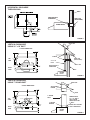
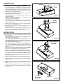
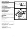
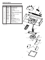
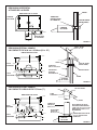
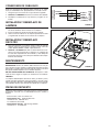
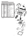
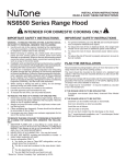
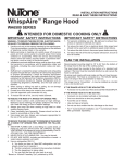
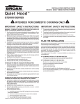
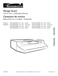
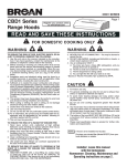
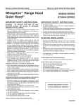
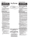
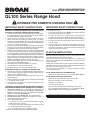
INSTALLATION INSTRUCTIONS
READ & SAVE THESE INSTRUCTIONS!
QL100 Series Range Hood
!
INTENDED FOR DOMESTIC COOKING ONLY
!
IMPORTANT SAFETY INSTRUCTIONS
IMPORTANT SAFETY INSTRUCTIONS
WARNING – TO REDUCE THE RISK OF FIRE, ELECTRIC SHOCK,
OR INJURY TO PERSONS, OBSERVE THE FOLLOWING:
1. Usethisunitonlyinthemannerintendedbythemanufacturer.
Ifyouhavequestions,contactthemanufacturerattheaddress
ortelephonenumberlistedinthewarranty.
2. Before servicing or cleaning unit, switch power off at service
panel and lock service panel to prevent power from being
switchedonaccidentally.Whentheservicedisconnectingmeans
cannotbelocked,securelyfastenaprominentwarningdevice,
suchasatag,totheservicepanel.
3. Installationworkandelectricalwiringmustbedonebyaqualified
person(s)inaccordancewithallapplicablecodesandstandards,
includingfire-ratedconstructioncodesandstandards.
4. Sufficientairisneededforpropercombustionandexhausting
ofgasesthroughtheflue(chimney)offuelburningequipment
topreventbackdrafting.Followtheheatingequipmentmanufacturer’sguidelineandsafetystandardssuchasthosepublished
by the National Fire ProtectionAssociation (NFPA), and the
AmericanSocietyforHeating,RefrigerationandAirConditioning
Engineers(ASHRAE),andthelocalcodeauthorities.
5. Whencuttingordrillingintowallorceiling,donotdamageelectricalwiringandotherhiddenutilities.
6. Ductedfansmustalwaysbeventedtotheoutdoors.
7. Usewithapprovedcord-connectionkitonly.
8. Toreducetheriskoffire,useonlymetalductwork.
1. Forindooruseonly.
2. Forgeneralventilatinguseonly.Do notusetoexhausthazardousorexplosivematerialsandvapors.
3. Toreducetheriskoffireorelectricalshock,thisrangehood
shouldnotbeusedwithanadditionalspeedcontroldevice.
4. Toreducetheriskofshock,disconnectpowerbeforeservicing.
5. Toreducetheriskoffireandtoproperlyexhaustair,besureto
ductairoutside.
6. Yourhoodmotorhasathermaloverloadwhichwillautomaticallyshutoffthemotorifitbecomesoverheated.Themotorwill
restartwhenitcoolsdown.Ifthemotorcontinuestoshutoffand
restart,havethehoodserviced.
TO REDUCE THE RISK OF A RANGE TOP GREASE FIRE:
1. Neverleavesurfaceunitsunattendedathighsettings.Boilovers
causesmokingandgreasyspilloversthatmayignite.Heatoils
slowlyonlowormediumsettings.
2. AlwaysturnhoodONwhencookingathighheatorwhencookingflamingfoods.
3. Cleanventilatingfansfrequently.Greaseshouldnotbeallowed
toaccumulateonfanorfilter.
4. Useproperpansize.Alwaysusecookwareappropriateforthe
sizeofthesurfaceelement.
TO REDUCE THE RISK OF INJURY TO PERSONS IN THE EVENT
OF A RANGE TOP GREASE FIRE, OBSERVE THE FOLLOWING*:
1. SMOTHER FLAMES with a close-fitting lid, cookie sheet, or
metaltray,thenturnofftheburner.BECAREFULTOPREVENT
BURNS.Iftheflamesdonotgooutimmediately,EVACUATE
ANDCALLTHEFIREDEPARTMENT.
2. NEVERPICKUPAFLAMINGPAN-Youmaybeburned.
3. DONOTUSEWATER,includingwetdishclothsortowels-a
violentsteamexplosionwillresult.
4. UseanextinguisherONLYif:
A. You know you have a ClassABC extinguisher, and you
alreadyknowhowtooperateit.
B. Thefireissmallandcontainedintheareawhereitstarted.
C. Thefiredepartmentisbeingcalled.
D. Youcanfightthefirewithyourbacktoanexit.
*Basedon“KitchenFiresafetyTips”publishedbyNFPA.
PLAN THE INSTALLATION
Recommendedmountingheightis18”to24”fromthebottomofthe
rangehoodtothetopofthecookingsurface.
The hood should be mounted to the bottom of a standard wall
cabinet.Ifthehoodmustbemounteddirectlytoawall,securethe
hoodtowallstuds.
Allwiringmustcomplywithlocalcodesandtheunitmustbeproperly
grounded.Thehoodisconnectedtoa110-120vAClightingcircuit
(15amp)inthecircuitbreakerorfusebox.
Thisrangehoodis“Convertible”–itmaybeinstalledasaducted
orasanon-ductedunit.
IF THE RANGE HOOD IS TO BE NON-DUCTED:
Purchasenon-ducted(duct-free)charcoalfilterModelBPQTF.
IF THE RANGE HOOD IS TO BE DUCTED:
Ductworkcanbeinstalledverticallyorhorizontally.
Ductrunsshouldbeasshortaspossible.
Avoidtheuseofelbows.
Useducttapeatalljoints.
Donotuseductsmallerthanthedischargeonthehood.
For7”roundductworkinstallation,use7”rounddamper,Model
BP87(97010792)Purchaseddamperseparately.
Registeryourproductonlineat:www.broan.com/register
HORIZONTAL DISCHARGE
THROUGH WALL
WALL
SUPPLIED DUCT
TRANSITION
WALL CAP
(Model 838AL)
RANGE HOOD
FIGURE 1
ROOF CAP
VERTICAL DISCHARGE
USING 3¼” x 10” DUCT
CUTOUT DIMENSIONS
1"
CL
ELBOW
TOP
VIEW
EAVE CAP
(Model 836AL)
1
12"
3¼" x 10"
DUCT
9"
31/4" x 10"
3/4"
BACK
VIEW
2"
1"
CL
ELEC. K.O.
31/4" x 10"
WALL CAP
SUPPLIED DUCT
TRANSITION
3/8"
WALL
6"
RANGE
HOOD
FIGURE 2
VERTICAL DISCHARGE
USING 7” ROUND DUCT
ROOF CAP
CUTOUT DIMENSIONS
ADJUSTABLE
ELBOW
1"
CL
ROOF
TOP
VIEW
1
7" ROUND
DUCT
7" DIA
12"
9"
5"
BACK
VIEW
3/4"
2"
ELEC. K.O.
REMOVE BOTH
3¼" x 10" AND 7"
HALF ROUND
KNOCKOUTS FOR
7" DUCT
CL
7" ROUND
DAMPER
7/8"
SUPPLIED 7" ROUND
DUCT TRANSITION
RANGE
HOOD
6"
FIGURE 3
2
PREPARATION
LOCATORS
1. Use the dimensional drawings (Refer to FIGURES 1 - 3) to
lay out the range hood’s mounting holes, wiring access and
ductwork by marking the cabinet bottom and drywall where
applicable.NOTE:Cabinetswithrecessedbottomswillrequire
woodshimstomakemountingsurfaceflushwithcabinetframe.
2. Makecutoutsforwiringandductwork.
3. Ifthehoodistobeducted,installtheductworksothatisflush
totherangehood’smountingsurface.
Refer to FIGURE 1 iftherangehoodistobeinstalledwitha
horizontaldischarge.
Refer to FIGURE 2 and FIGURE 3iftherangehoodistobe
installedwithaverticaldischarge.
4. Runtwo-conductorwire(withground)fromapowersourceto
the hood location. Bring approximately 12” of wiring through
wiringholeincabinet.
5. Drillfour3/32”diameterpilotholesatpointswheremounting
holesaremarkedincabinetbottom.
6. Insert four (4) mounting screws, leaving approximately ¼” of
threadexposed.
7. Removeandretainthemountingscrewssecuringthe3¼”x10”
and7”ducttransitionstothehood.Installtheappropriateduct
transitionasdescribedintheinstallationsection.
BAFFLE
PLATE
FIGURE 4
7” ROUND
ADAPTER
(INCLUDED)
INSTALLATION
1. Removethenecessaryductopeningandwiringknockoutfrom
therangehood.
If the range hood is to be installed as a non-ducted unit,
removethewiringknockoutonly.
If the range hood is to be installed as a ducted unit,abaffle
plateisprovidedtocloseoffthenon-ductedvent.Installbaffle
plate(Refer to FIGURE 4)byslidingintoplacebehindgrille.
Uselocatorbumpstoorientingrille.
2. For 7” round discharge installation, refer to FIGURE 5.Secure7”adapter(included)totopofhoodusingscrewsprovided.
Install7”rounddamper(ModelBP87(97010792),purchased
separately).
For 3¼” x 10” vertical discharge installation, refer to FIGURE
6.Secure3¼”x10”transition(ifused)totopofhood.
For 3¼” x 10” horizontal discharge installation, refer to FIGURE 7.Ifusingsupplied3¼”x10”ducttransition,secureitto
therangehood.Ensurethatthedamperflapoperatesfullyand
freely.Ifitdoesnot,removethedamperflapormakenecessary
modificationstotheinstallationtoinsurefullandfreeoperation
ofthedamperflap.
3. Feedthewiringthroughtheaccessholdandintotheelectrical
box.
4. Alignhood’skeyholemountingslotsoverthefour(4)partially
installedscrews.
5. Makingsuretheduct positionsoverthehood’sducttransition,
pushthehoodagainsttherearwall.Securehoodbytightening
screws.
6. Usingalongbladescrewdriver,reachintothedischargeopening and make sure the damper flap operates freely (vertical
dischargeonly).
FIGURE 5
SECURE TRANSITION
WITH SCREWS
(INCLUDED)
FIGURE 6
POSITION DUCT
TRANSITION IN
WALL CUTOUT
3
HORIZONTAL
FIGURE 7
WIRING CONNECTIONS
HOOD WIRING
LAMP INSTALLING
OR REPLACEMENT
WHT
BLK
WHT
GREEN GROUND
SCREW
BLK
GREEN
OR BARE
(GROUND)
SUPPLY WIRING
Allwiringconnectionsmustcomplywithlocalcodesandtheunit
mustbeproperlygrounded.
1. Makesureboxconnectorissecure.
2. Refer to FIGURE 8.Makewiringconnections.
3. Replaceelectricalboxcoverandsecurewithscrew.
FIGURE 8
1. Depresssidesoflightdiffuseruntiltabsofdiffuserdisengage
fromslotsinhood.Removediffuser.
2. Install(2)60wattmaximum,TypeA-19bulbs.
3. Replacedifuserinhoodbydepressingsidesandengagingtabs
inslotsinhood.
FILTER INSTALLATION
AND REPLACEMENT
1. Forductedoperation,installthealuminummeshfilter.Fornonductoperation,installthenon-ductedfilter(ModelBPQTF,sold
separately).
2. Refer to FIGURE 9.Thefilterslidesintochannelsattheback
ofthehood,oneithersideofthefancompartment,andsnaps
underthespringclipsnearthefrontofthefancompartment.
MAINTENANCE
FILTERS
IMPORTANT:Thealuminumfiltershouldberemovedoncemonthly
andwashedinhotdetergentwater.Rinseinclear,warmwaterand
shakeoffexcessmoisturebeforereplacing.Thefiltermayalsobe
cleanedinyourdishwasher.
IN A NON-DUCTED INSTALLATION: Replace filter every 3-6
monthsasneeded.
FIGURE 9
CLEANING
Thehoodshouldbewipedoffoccasionallybothinsideandoutside
usingwarmwater,milddishdetergentandasoftcloth.Neveruse
scouringpowders,steelwoolpadsoranyotherabrasivecleaners
whichwilldestroythehood’sfinish.
REPLACEMENT PARTS
Shouldreplacementpartsberequired,pleaseindicatehoodmodel
numberandappropriatepartnumber.ContactyourBroandealer
orNuToneat:
IntheU.S.contact:
Broan-NuTone LLCHartford,Wisconsin
www.broan.com800-558-1711
IntheCanadacontact:
Broan-NuTone Canada Mississauga,Ontario
www.broan.ca877-896-1119
4
SERVICE PARTS
KEY NO.
PART NO.
1
2
3
4
5
6
7
8
9
10
11
12
13
14
*
*
*
R680508
R99360244
R99360247
R401658
R401659
R740014
99080666
99271236
R566097
R531076
R607225
R99091072
R99091073
R680541
R401650
R610092
R561138
R111658
R111687
99010317
DESCRIPTION
1
7-in.RoundDuctPlate
Knob,White(2req.)
Knob,Biscuit(2req.)
Grille,White
Grille,Biscuit
3¼”x10”DamperAssembly
Motor
LampSocketAssembly(ShortWires)
LampSocketAssembly(LongWires)
FanBlade
ExternalHitchPin(Hairpin)
Baffle,White
Baffle,Biscuit
WiringCover
LightLens
AluminumFilter
Fan&LightSwitch(2req.)
RectifierAssembly(NightLight)
WireHarness
(includesswitches&rectifier)
Non-DuctedFilter
(Purchaseseparately)
14
2
3
OrderreplacementpartsbyPARTNO.-notbyKEYNO.
*Notillustrated
4
5
6
7
10
8
9
11
12
13
5
WARRANTY
BROAN-NUTONE ONE YEAR LIMITED WARRANTY
Broan-NuTone warrants to the original consumer purchaser of its products that such products will be free from defects
in materials or workmanship for a period of one year from the date of original purchase. THERE ARE NO OTHER
WARRANTIES, EXPRESS OR IMPLIED, INCLUDING, BUT NOT LIMITED TO, IMPLIED WARRANTIES OF
MERCHANTABILITY OR FITNESS FOR A PARTICULAR PURPOSE.
During this one-year period, Broan-NuTone will, at its option, repair or replace, without charge, any product or part which
is found to be defective under normal use and service.
THIS WARRANTY DOES NOT EXTEND TO FLUORESCENT LAMP STARTERS, TUBES, HALOGEN AND
INCANDESCENT BULBS, FUSES, FILTERS, DUCTS, ROOF CAPS, WALL CAPS AND OTHER ACCESSORIES FOR
DUCTING. This warranty does not cover (a) normal maintenance and service or (b) any products or parts which have
been subject to misuse, negligence, accident, improper maintenance or repair (other than by Broan-NuTone), faulty
installation or installation contrary to recommended installation instructions.
The duration of any implied warranty is limited to the one-year period as specified for the express warranty. Some states
do not allow limitation on how long an implied warranty lasts, so the above limitation may not apply to you.
BROAN-NUTONE’S OBLIGATION TO REPAIR OR REPLACE, AT BROAN-NUTONE’S OPTION, SHALL BE THE
PURCHASER’S SOLE AND EXCLUSIVE REMEDY UNDER THIS WARRANTY. BROAN-NUTONE SHALL NOT BE
LIABLE FOR INCIDENTAL, CONSEQUENTIAL OR SPECIAL DAMAGES ARISING OUT OF OR IN CONNECTION WITH
PRODUCT USE OR PERFORMANCE. Some states do not allow the exclusion or limitation of incidental or consequential
damages, so the above limitation or exclusion may not apply to you.
This warranty gives you specific legal rights, and you may also have other rights, which vary from state to state. This
warranty supersedes all prior warranties.
To qualify for warranty service, you must (a) notify Broan-NuTone at the address or telephone number below, (b) give
the model number and part identification and (c) describe the nature of any defect in the product or part. At the time of
requesting warranty service, you must present evidence of the original purchase date.
Broan-NuTone LLC, 926 W. State Street, Hartford, Wisconsin 53027 www.broan.com
Broan-NuTone Canada, Inc., 1140 Tristar Drive, Mississauga, Ontario L5T 1H9 www.broan.ca
800-558-1711
877-896-1119
Productspecificationssubjecttochangewithoutnotice.
Rev.2/12,PartNo.628029G
INSTRUCCIONES DE INSTALACION
¡LEA Y GUARDE ESTAS INSTRUCCIONES!
Campana de Cocina Serie QL100
!
PREVISTO PARA COCINAR DOMÉSTICO SOLAMENTE.
!
INSTRUCCIONES IMPORTANTES
DE SEGURIDAD
INSTRUCCIONES IMPORTANTES
DE SEGURIDAD
CUIDADO – PARA REDUCIR EL RIESGO DE FUEGO, DESCARGA
ELECTRICA, O LESIONES A PERSONAS, OBSERVE LO SIGUIENTE:
1. Useestaunidadsolamenteenlamaneraalaquefuedestinada
porelfabricante.Sitienecualquierpregunta,póngaseencontacto
conelfabricantealadirecciónyteléfonoenlistadoenlasección
delagarantía.
2. Antesdelimpiarodeponerenserviciolaunidad,apagueelinterruptorenelpaneldeservicioparaevitarqueseenciendaaccidentalmente.Cuandoeldispositivoparadesonectarelservicioeléctrico
nopuedesercerradoconalgúntipodetraba,sujetefuertemente
alpaneldeservicio,unaetiquetadeadvertenciaprominente.
3. Una persona calificada debe de hacer el trabajo de instalación
delcableadoeléctricodeacuerdoconloscódigosyestándares
aplicables.
4. Paracualquierequipoquequemacombustibleesnecesariotener
elairesuficienteaireparaquehayacombustiónapropiadaysalida
delosgasesatravésdelachimeneayasíprevenirqueestosgases
seregresen.Sigalasdirectivasdelfabricantedelequipodecalentar
ylosestándaresdeseguridadcomolosquehansidopublicados
por la National Fire ProtectionAssociation (NFPA) (Asociación
NacionaldeProteccióndeFuego)ylaAmericanSocietyforHeating,RefrigerationandAirConditioningEngineers(ASHRAE)(La
SociedadAmericanadeIngenierosparaCalefacción,Refrigeración
yAireAcondicionado)ylasautoridaresdecódigolocales.
5. Cuando corte o perfore una pared o techo, no haga daño a los
alambreseléctricosyotrasinstalacionesocultas.
6. Ventiladoresoabanicosqueusanductosdebensiempredescargar
elairealexterior.
7. Usoconelkitaprobadodellaconexióndelacuerdasolamente.
8. Parareducirelriesgodefuegousesolamenteductosdemetal.
PARA REDUCIR EL RIESGO DE UN INCENDIO DE GRASA ENCIMA
DE LA ESTUFA:
1. Nuncadejesinatenderlasunidadesdesuperficiecuandotengan
ajustes altos. Los reboses pueden provocar humo y derrames
grasososquesepuedenincendiar.Calientelentamenteelaceite
enunajustebajoomedio.
2. SiempreENCIENDAlacampanacuandococineconaltatemperaturaocuandococinealimentosquesepuedanincendiar.
3. Limpié con frecuencia los ventiladores. No debe permitir que la
grasaseacumuleenelventiladornienelfiltro.
4. Utiliceunsarténdetamañoadecuado.Siempreutiliceelutensilio
adecuadoaltamañodelelementodesuperficie.
PARA REDUCIR EL RIESGO DE LESIONES A PERSONAS EN EL
CASO DE UN INCENDIO DE GRASA ENCIMA DE LA ESTUFA,
OBSERVE LO SIGUIENTE:*
1. AHOGUELASLLAMASconunatapaquecierraapretadamente,
unaláminaparagalletasounabandejademetalyentoncesapague
elquemador.ESTESEGUROENNOQUEMARSE.Silasllamas
noseapaganinmediatamente,DESOCUPELACOCINAYCASA
YLLAMEALOSBOMBEROS.
2. NUNCA LEVANTE UNA OLLA QUE ESTE INCENDIANDOSE -
Ustedpuedequemarse.
3. NO USEAGUA, incluyendo trapos o toallas mojadas ya que el
usarlosresultaráenunaexplosiónviolenta.
4. UseunextinguidorSOLAMENTEsi:
A. UstedsabequetieneunextinguidordelaClaseABCy
ustedyasabecómooperarlo.
B. Elfuegoespequeñoyestácontenidoeneláreadondecomenzó.
C. Seestéllamandoalosbomberos.
D. Ustedpuedetratardeapagarelfuegoconsuespalda
haciaunasalida.
*Basadoenlos“KitchenFiresafetyTips”(ConsejosparaSeguridadde
FuegoenlaCocina)publicadoporlaNFPA.
INSTRUCCIONES IMPORTANTES
DE SEGURIDAD
1. Paraelusodeinteriorsolamente.
2. Para uso de ventilación general solamente. No lo use para extraer
materialesovaporesexplosivosopeligrosos.
3. Parareducirelriesgodeincendioodeelectrocución,nosedebeusar
la campana de esa cocina con un elemento adicional de control de
velocidad.
4. Parareducirelriesgodeelectrocución,desconectelaalimentaciónantes
deprestarservicio.
5. Asegúresedeagotarelaireporconductoshaciaelexterior,parareducir
elriesgodeincendioyparaagotarapropiadamenteelaire.
6. Estemotordecampanatieneunaproteccióncontrasobrecargastérmicas
queautomáticamenteapagaráelmotorencasodesobrecalentamiento.
Elmotorreanudarásufuncionamientocuandoseenfríe.Sielmotorcontinúaapagándoseyencendiéndose,soliciteservicioparalacampana.
PLANEAMIENTO
Laalturarecomendadaparamontajeesde45,72a60,96cm(18a24pulgadas)
desdelaparteinferiordelacampanadelacocinahastalapartesuperiordela
superficieparacocinar.
Lacampanadebemontarseenlaparteinferiordeunarmarionormaldepared.
(Asegurelacampanaalospernosdemontajedelapared,silacampanadebe
montarsedirectamenteenlapared.).
Todoelcableadodebecumplirconlascódigoslocalesylaunidaddebeestar
adecuadamenteconectadaatierra.Lacampanaestconectadaauncircuitode
iluminaciónde110-120VCA(15Amp)enelinterruptordecircuitoocajadefusibles.
Esta campana de cocina es“convertible”, puede instalarse como una unidad
conectadaonoconectadaaconductos.
SI LA CAMPANA DE COCINA NO SE CONECTA A CONDUCTOS:
Compreunfiltrodecarbónsinconductos(libredeconductos)ModeloBPQTF.
SI LA CAMPANA DE COCINA SE CONECTA A CONDUCTOS:
Losconductospuedeninstalarseverticalohorizontalmente.
Lostramosdeconductodebensertancortoscomoseaposible.
Eviteelusodecodos.
Usecintaparaconductosentodaslajuntas.
Nouseunconductomáspeque(oqueladescargadelacampana).
Parainstalacióndeconductoscircularesde17,78(7”),useunreguladorcircularde17,78cm(7”),ModeloBP87(97010792).Comprereguladorcircular
separado.
Registresuproductoenlíneaen:www.broan.com/register
DESCARGA HORIZONTAL
A TRAVES DE LA PARED
PARED
DIMENSIONES DE LA SALIDA
ARMARIO
DE COCINA
TRANSICION
PROVISTA PARA
EL CONDUCTO
19,05
cm
TAPA DE PARED
(Modelo 838AL)
CAMPANA
DE COCINA
1,91 cm
9,84 cm
ORIFICIO PARA
EL CABLEADO
13,34
cm
26,67
cm
FIGURA 1
TAPA E TECHO
DESCARGA VERTICAL USANDO
UN CONDUCTO DE 8,26 cm x 25,40 cm (3¼ x 10”)
(Modelo 634 o 644)
DIMENSIONES DE SALIDA
CL
2, 54 cm
CODO
44,45 cm
VISTA
SUPERIOR
30,48
cm
22,86 cm
8,26 x 25,40 cm
5,08 cm
1,91 cm
ELEC. K.O.
VISTA
POSTERIOR
19,05
cm
3,81 cm
2,54 cm
1 cm
CL
8,26 x 25,40 cm
3,81 cm
TAPA DE ALERO
(Modelo 836AL)
CONDUCTO
8,26 cm x 25, 40 cm
TRANSICION
PROVISTA
DE CONDUCTO
TAPA DE PARED
PARED
15,24 cm
CAMPANA
DE COCINA
DESCARGA VERTICAL USANDO
UN CONDUCTO CIRCULAR DE 17,78 cm (7”)
TAPA DE TECHO
CODO
AJUSTABLE
DIMENSIONES DE SALIDA
CL
FIGURA 2
2, 54 cm
TECHO
CONDUCTO
CIRCULAR
DE17,78 cm
17,78 cm Dia.
(7" Dia.)
44,45 cm
VISTA
SUPERIOR
30,48
cm
22,86 cm
REGULADOR
CIRCULAR
DE 17,78 cm
12,7 cm
5,08 cm
1,91 cm
VISTA
POSTERIOR
QUITE AMBAS TAPAS DE
AGUJEROS PREPUNZADAS,
LA DE 8,26 cm x 25, 4 cm Y EL
MEDIO CIRCULO DE 17,8 cm
DE DIAMETRO
ELEC. K.O.
19,05
cm
CL
2,22 cm
3,81 cm
CAMPANA
DE COCINA
15,24 cm
TRANSICION CIRCULAR DE
17,78 cm PROVISTA DE
CONDUCTO
FIGURA 3
8
PREPARACION
LOCALIZADORES
1. Uselosdibujosdimensionales (FIGURAS 1 - 3) paradisponer
losorificiosdemontajedelacampana,accesodelcableadoy
conductos,marcandoelfondodelarmarioyeltabiquedonde
seaaplicable.NOTA:Losgabinetesconlosfondosahuecados
requeriránlascalzasdemaderahacerrubordelasuperficie
demontajeconelmarcodegabinete.
2. Efectoeloscortesparaelcableadoyelconducto.
3. Instaleelconductodemaneraqueestéalrasconlasuperficie
demontajedelacampanadecocina,silacampanaseconecta
aunconducto.
Silacampanadelacocinaseinstalaconunadescargahorizontal,refiérase a la FIGURA 1.
Silacampanadelacocinaseinstalaconunadescargavertical,
refiérase a las FIGURAS 2 y 3.
4. Tienda un cable de dos conductores (con conexión a tierra)
desdeunafuentedepotenciaalaubicacióndelacampana.
Traiga30,48cm(12”)decableadoaproximadamenteatravés
delorificiodecableadoenelarmario.
5. Taladrecuatroorificiospilotode0,24cm(3/32”)dediámetro
enlospuntosdondeestánmarcadoslosorificiosdemontaje
enelfondodelarmario.
6. Insertecuatro(4)tornillodemontaje,dejandoaproximadamente
0,64cm(1/4”)deroscaexpuesta.
7. Extraiga y guarde los tornillos de montaje, asegurando las
transicionesdeconductode8,26cmx25,40cm(3¼”x10”)y
17,78cm(7”)alacampana.Instalelatransicióndeconducto
apropiadasegúnsedescribeenlaseccióndeinstalación
PLACA
DEFLECTORA
FIGURA 4
ADAPTADOR
CIRCULAR DE
17,78 cm (7 pulg.)
(incluido)
INSTALACIÓN
FIGURA 5
1. Extraigalaaberturadeconductoyelorificiociegodecableado
necesarios,delacampanadecocina.
Si la campana de cocina se instala como una unidad sin
conductos, extraigaelorificiociegodelcableadosolamente.
Si la campana de cocina se instala como una unidad con
conducto, seproveeunaplacadeflectoraparacerrarelventiladorsinconducto.Instalelaplacadeflectora(refiérase a la
FIGURA 4)deslizandoensulugardetrosdelarejilla.Uselas
salientesdellocalizadorparaorientarenlarejilla.
2. Para una instalación de descarga circular de 17,78 cm (7”),
refiérase a la FIGURA 5.Asegureeladaptadorde17,78cm(7”)
(incluido)altopedelacampanausandolostornillosprovistos.
Instale regulador redondo de 17,78 cm de diámetro (Modelo
BP87(97010792),secompraporseparado).
Para una instalación de descarga vertical, refiérase a la
FIGURA 6.Asegurelatransiciónde8,26cmx25,40cm(3¼”
x10”)(siusada)altopedelacampana.
Para una instalación de descarga horizontal refiérase a la
FIGURA 7.Siestáutilizandoeltransicióndelconductode8,26
cmx25,40cm(3¼”x10”),asegúreloalacampana.Asegúrese
dequelaaletamáshúmedafuncionecompletamenteylibremente.Sino,quitarlaaletamáshúmedaohacermodificaciones
necesariasalainstalaciónparaasegurarlaoperacióncompleta
ylibredelaaletamáshúmeda.
3. Alimenteelcableadoatravésdelorificiodeaccesoydentrode
lacajaeléctrica.
4. Alineelasranurasdemontajedelachiveterodelacampana
sobreloscuatro(4)tornillosparcialmenteinstalados.
5. Asegurándosequeelconductoestéenposiciónsobrelatransicióndelconductodelacampana,empujeestaúltimacontra
laparedposterior.Asegurelacampana,ajustandolostornillos.
6. Usando un destornillador de hoja larga, llegue a la abertura
de descarga y asegúrese que la aleta del regulador opere
libremente(verticalsolamente).
ASEGURE LA
TRANSICIÓN CON LOS
TORNILLOS (incluidos)
FIGURA 6
COLOQUE EN POSICION LA
TRANSICIÓN DEL CONDUCTO
EN LA SALIDA DE LA PARED
9
HORIZONTAL
FIGURA 7
CONEXIONES DE CABLEADO
CABLEADO DE
LA CAMPANA
INSTALACION Y REEMPLAZO DE
LAMPARA
BLANCO
BLANCO
NEGRO
TORNILLO VERDE
DE CONEXION
A TIERRA
NEGRO
VERDE O
EXPUESTO
(A TIERRA)
CABLEADO DE
ALIMENTACION
Todas las conexiones de cableado deben cumplir con el código
localylaunidaddebeestarapropiadamenteconectadaatierra.
1. Asegúresequeelconectordelacajaestébienasegurado.
2. Refiérase a la FIGURA 8.Efectúelasconexionesdelcableado.
3. Reemplacelacubiertadelacajaeléctricayasegureconun
tornillo.
FIGURA 8
1. Aprietelosladosdeldifusordeluzhastaquesedesenganchen
lasaletasdeldifusordelasranurasenlacampana.
2. Instale(2)lámparasdeTipoA-19de60vatiosmáximo.
3. Vuelvaacolocareldifusorenlacampanaapretandoloslados
yenganchandolasaletasenlasranurasdelacampana.
INSTALACION Y REEMPLAZO
DE FILTRO
1. Paraunaoperaciónconconductoinstaleelfiltrodemallade
aluminio.Paraunaoperaciónsinconducto,instaleelfiltrode
carbón(ModeloBPQTF,vendidoseparadamente).
2. Refiérase a la FIGURA 9.Elfiltrosedeslizadentrodecorrederasenlaparteposteriordelacampana,encualquierade
losladosdelcompartimientodelventilador,ycalzadebajode
losbrochesdelresortecercadelapartedelanteradelcompartimientodelventilador.
MANTENIMIENTO
FILTROS
IMPORTANTE: El filtro de aluminio debe extraerse una vez por
mesylavarseenaguacalientecondetergente.Enjuagueenagua
limpia,tibiaysacudaelaguasobranteantesdevolveracolocar.El
filtropuedetambiénlimpiarseensulavadoradeplatos.
EN UNA INSTALACION SIN CONDUCTO: Reemplace el filtro
cada3-6mesessegúnserequiera,eninstalacionessinconducto.
FIGURA 9
LIMPIEZA
Lacampanadebelimpiarsedetantoentanto,pordentroyfuera,
usandoaguatibia,detergentesuaveparaplatosyuntraposuave.
Nuncausepolvosabrasivos,almohadillasdelanadeaceroniningún
otrolimpiadorabrasivoquedestruiráelacabadodelacampana.
PIEZAS DE REPUESTO
Indiqueporfavorelnúmerocorrectodelapieza,sirequierepiezas
de repuesto. Consulte con sus distribuidores Broan o escriba a
NuTone:
EnlosE.E.U.U.,entreencontactocon:
Broan-NuTone LLCHartford,Wisconsin
www.broan.com800-558-1711
LosresidentesdeCanada:
Broan-NuTone Canada Mississauga,Ontario
www.broan.ca877-896-1119
10
PIEZAS DE SERVICIO
NO.
CODIGO
NO.
PIEZA
DESCRIPCION
1
2
3
4
5
6
7
8
9
10
11
12
13
14
*
*
*
R680508
R99360244
R99360247
R401658
R401659
R740014
99080666
99271236
R566097
R531076
R607225
R99091072
R99091073
R680541
R401650
R610092
R561138
R111658
R111687
99010317
Placadeconductoredondode
17,78cm(7pulg.)
Botón,Blanco(2req.)
Botón,Beige(2req.)
Rejilla,Blanco
Rejilla,Beige
Ensamblajedeconductode
8,26cmx25,40cm(3¼x10pulg.)
Motor
Ensamblajedecasquillodeluz
(alambrescorto)
Ensamblajedecasquillodeluz
(alambreslargo)
Aletadeventilador
Pasadorexterno(horquilla)
Deflector,Blanco
Deflector,Beige
Cubiertadelosalambres
Lentedeluz
Filtrodealuminio
Interruptordeventiladoryluz(2req.)
Ensamblajederectificador
(luzdenoche)
Ensamblajedealambres
(incluyeinterruptoresyrectificador)
Filtrosinductoconductos
(compraseparado)
1
14
2
3
4
PidalaspiezasdeservicioporNO.CODIGO-noporNO.PIEZA.
*Noilustrado
5
6
7
10
8
9
11
12
13
11
GARANTIA
GARANTÍA BROAN-NUTONE LIMITADA POR UN AÑO
Broan-NuTone garantiza al consumidor comprador original de sus productos que dichos productos carecerán de defectos
en materiales o en mano de obra por un período de un año a partir de la fecha original de compra. NO EXISTEN
OTRAS GARANTÍAS, EXPLICITAS O IMPLÍCITAS, INCLUYENDO, ENTRE OTRAS, GARANTÍAS IMPLÍCITAS DE
COMERCIALIZACIÓN O APTITUD PARA UN PROPÓSITO PARTICULAR.
Durante el período de un año, y a su propio criterio, Broan-NuTone reparará o reemplazará, sin costo alguno, cualquier
producto o pieza que se encuentre defectuosa bajo condiciones normales de servicio y uso.
LA PRESENTE GARANTÍA NO CUBRE LOS TUBOS FLUORESCENTES NI SUS ARRANCADORES, BOMBILLAS
DE HALÓGENO E INCANDESCENTES, FUSIBLES, FILTROS, CONDUCTOS, TAPONES DE TECHO O PAREDES
Y DEMÁS ACCESORIOS PARA CONDUCTOS. Esta garantía no cubre (a) mantenimiento y servicio normales o (b)
cualesquiera productos o piezas que hayan sido utilizados de forma errónea, negligente, que hayan causado un
accidente, o que hayan sido reparados o mantenidos inapropiadamente (por otras compañías que no sean BroanNuTone), instalación defectuosa, o instalación contraria a las instrucciones de instalación recomendadas.
La duración de cualquier garantía implícita se limita a un período de un año como se especifica en la garantía expresa.
Algunos estados no permiten limitaciones en cuanto al tiempo de vencimiento de una garantía implícita, por lo que la
limitación antes mencionada puede no aplicarse a usted.
LA OBLIGACIÓN DE BROAN-NUTONE DE REPARAR O REEMPLAZAR, SIGUIENDO EL CRITERIO DE BROANNUTONE, DEBERÁ SER EL ÚNICO Y EXCLUSIVO RECURSO LEGAL DEL COMPRADOR BAJO ESTA GARANTÍA.
BROAN-NUTONE NO SERÁ RESPONSABLE POR DAÑOS INCIDENTALES, CONSECUENTES, O POR DAÑOS
ESPECIALES QUE SURJAN A RAÍZ DEL USO O DESEMPEÑO DEL PRODUCTO. Algunos estados no permiten
la exclusión o limitación de daños incidentales o consecuentes, por lo que la limitación antes mencionada puede no
aplicarse a usted.
Esta garantía le proporciona derechos legales específicos, y usted puede también tener otros derechos, los cuales varían
de estado a estado. Esta garantía reemplaza todas las garantías anteriores.
Para calificar para la garantía de servicio, usted debe (a) notificar a Broan-NuTone al domicilio o al número de teléfono
que se menciona abajo, (b) dar el número del modelo y la identificación de la pieza, y (c) describir la naturaleza de
cualquier defecto en el producto o la pieza. En el momento de solicitar servicio cubierto por la garantía, usted debe de
presentar un comprobante con la fecha original de compra.
Broan-NuTone LLC, 926 W. State Street, Hartford, Wisconsin 53027 www.broan.com
Broan-NuTone Canada, Inc., 1140 Tristar Drive, Mississauga, Ontario L5T 1H9 www.broan.ca
800-558-1711
877-896-1119
Lasespecificacionesdelproductoestánsujetasacambiosinprevioaviso.
Rev.2/12,Nodeparte628029G