1
14LK22
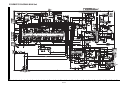
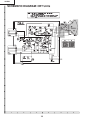
DESCRIPTION OF SCHEMATIC DIAGRAM
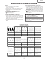
WAVEFORM MEASUREMENT CONDITIONS:
1. Photographs taken on a standard gated color bar
signal, the tint setting adjusted for proper color. The
wave shapes at the red, green and blue cathodes of
the picture tube depend on the tint, color level and
picture control.
2.
indicates waveform check points (See chart,
waveforms are measured from point indicated to
chassis ground.)
NOTES:
1. The unit of resistance "ohm" is omitted.
(K=kΩ=1000Ω, M=MΩ)
2. All resistors are 1/16 watt, unless otherwise noted.
3. All capacitors are µ F, unless otherwise noted.
(P=pF=µµF)
4. (G) indicates ±2% tolerance may be used.
5. indicates line isolated ground.
6. indicates hot ground.
å AND SHADED (
VOLTAGE MEASUREMENT CONDITIONS:
1. All DC voltages are measured with DVM connected
between points indicated and chassis ground, line
voltage set at 120V AC and all controls set for normal
picture unless otherwise indicated.
2. All voltages measured with 1000µ V B & W or Color
signal.
) COMPONENTS
= SAFETY RELATED PARTS.
' MARK= X-RAY RELATED PARTS.
This circuit diagram is a standard one, printed circuits
may be subject to change for product improvement
without prior notice.
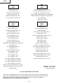
WAVEFORMS
11.00Vp-p
Horiz Rate
667Vp-p
Horiz Rate
q8.40Vp-p
Horiz Rate
22.8Vp-p
Horiz Rate
780Vp-p
Horiz Rate
w48.8Vp-p
Vert Rate
32.6Vp-p
Horiz Rate
83.00Vp-p
Vert Rate
e98Vp-p
Horiz Rate
15
42.7Vp-p
Horiz Rate
92.3Vp-p
Horiz Rate
r1200Vp-p
Horiz Rate
565Vp-p
Horiz Rate
0116Vp-p
Horiz Rate
t415Vp-p
Power Supply Rate