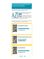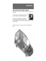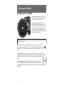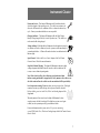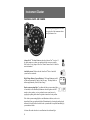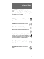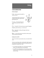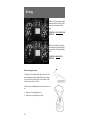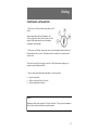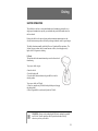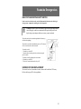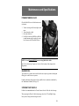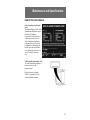
1
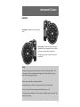
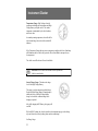
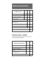
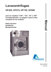
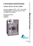
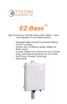
Service Assistance And Supplemental Information For Vehicle Owners And Operators Azure Dynamics vehicles are sold and serviced through a network of authorized dealers who will assist you with any periodic maintenance or service required for your vehicle. The information contained in this publication was current at time of publication,. To ensure that you have the most up-to-date reference on operation of your vehicle and its systems, Azure Dynamics provides updated and supplemental information on its Product Support website: AZDtec.com. The information below contains both normal URL links and special electronic ―QR‖ links that may be accessed through an appropriate reader on your web-enabled ―Smartphone‖. Supplemental Update Information http://azdtec.com/azdvehicles/ogs_updates/tce/ Or scan QR Bar Code at left. Authorized Azure Dynamics Dealer Locations http://azdtec.com/dealer/index.php Or scan QR Bar Code at left. Driver Orientation Video http://www.youtube.com/watch?v=yjw8EVehflU Or scan QR Bar Code at left. P/N 107384-A, 9/8/2011 Introduction INTRODUCTION 2 INSTRUMENT CLUSTER 6 CLIMATE CONTROLS 13 TIRES, WHEELS & LOADING 14 DRIVING 15 ROADSIDE EMERGENCIES 21 CLEANING 24 MAINTENANCE & SPECIFICATIONS 25 SCHEDULED MAINTENANCE 32 HIGH VOLTAGE BATTERY CHARGING 35 3 Introduction OVERVIEW The Transit Connect Electric is an electric vehicle produced by Azure Dynamics Corporation and Ford Motor Company. The vehicle is powered by a high voltage traction motor—mounted under the hood— which drives the front wheels through a transmission. Power for the motor is supplied by a high voltage battery pack which is mounted under the cargo area forward of the rear wheels. A junction box—mounted underneath the floor between the front seats—provides a connection point between the high voltage battery and other system components. High Voltage wiring is identified with distinctive orange cabling. DRIVER CONTROLS All Driver controls are used as they would be on a standard Transit Connect. This includes power steering, power brakes, gear selection, and climate controls. ELECTRICAL OPERATION The Transit Connect Electric uses both High Voltage and Low Voltage systems. A conventional 12 V battery maintains normal vehicle systems, however it is maintained by the High Voltage Battery. All electrical power used comes from this High Voltage Battery, which is maintained by recharging the vehicle from an external source. See the High Voltage Battery Charging chapter at the back of this Supplement for details. 4 Introduction VEHICLE HIGH VOLTAGE BATTERY CHARGING A charge port for external AC power is provided on the right side of the vehicle behind the filler door. An on-board charger is located under the hood and is electrically connected to the charge port and the High Voltage Battery. NOTE: Electric Vehicle Supply Equipment (EVSE) must be properly and safely connected to the electrical grid to ensure proper vehicle charging. Always have a certified Electrician install any EVSE or outlets to support an EVSE. See the High Voltage Battery Charging chapter at the back of this Supplement for details. 5 Instrument Cluster WARNING LIGHTS AND CHIMES Warning lights and gauges can alert you to a vehicle condition that may become serious enough to cause expensive repairs. A warning light may illuminate when a problem exists with one of your vehicle’s functions. Many lights will illuminate—as a check—when you start your vehicle. If any light remains on after starting the vehicle, refer to the respective system warning light for additional information. The following warning lights are located on the left side of the instrument cluster on the Range Indicator face. Power Limit: This lamp will illuminate (solid) to indicate that the estimated range is less than 0.5 kilometers (0.3miles), or that the vehicle power output is being limited. The vehicle can continue to be driven with a solid Power Limit lamp. This lamp will flash to indicate a condition where the vehicle power output is being significantly limited. If the Power Limit lamp is flashing, safely manoeuvre the vehicle to the side of the road and have the vehicle towed to an authorized AZD repair facility. Anti-lock brake system: If the ABS light stays illuminated or continues to flash, a malfunction has been detected, have the system serviced by your authorized dealer. Normal braking is still functional unless the brake warning light also is illuminated. . 6 Instrument Cluster Powertrain Service: This lamp will illuminate (solid) to indicate that the vehicle has logged a fault requiring service. The vehicle can continue to be driven; the Powertrain Service condition will be re-evaluated at the next keycycle. Contact your authorized dealer as soon as possible. Charging Indicator: This lamp will illuminate while the High Voltage Battery is being charged if the key is in the II position (on). The vehicle can not be started while being charged. Airbag readiness: If this light fails to illuminate when the ignition is turned to on, continues to flash or remains on, have the system serviced immediately by your authorized dealer. A Chime will sound when there is a malfunction in the indicator light. Speed Control: Refer to the Driver Controls chapter of the Ford Transit Connect Owner’s Guide for more information. Stop Safely Hazard Warning: This lamp will illuminate to indicate an high voltage component fault/failure that will cause the vehicle to shutdown, fail to start, or enter a limited operating mode. Note: If the vehicle is still on, the vehicle may soon shutdown without further warning and should be stopped safely. Safely maneuver the vehicle to the side of the road and have the vehicle towed to an authorized AZD repair facility. Low tire pressure warning: Illuminates when your tire pressure is low. If the light remains on at start up or while driving, the tire pressure should be checked. Refer to Inflating your tires in the Tires, Wheels and Loading chapter of this Supplement. When the ignition is first turned to on, the light will illuminate for three seconds to ensure the bulb is working. If the light does not turn on or begins to flash, have the system inspected by your authorized dealer. For more information on this system, refer to Tire pressure monitoring system (TPMS) in the Tires, Wheels and Loading chapter of the Ford Transit Connect Owner’s Guide. 7 Instrument Cluster WARNING LIGHTS AND CHIMES The following warning lights are located on the right side of the instrument cluster on the Speedometer face. AdvanceTrac® This lamp illuminates when the AdvanceTrac® is active. If the light remains on, contact your authorized dealer as soon as possible. Refer to the Driving chapter of the Ford Transit Connect Owner’s Guide for more information. Anti-theft system: Flashes when the SecuriLock® Passive Anti-theft system has been activated. High Voltage Battery (Layered Battery): This lamp illuminates (solid) to indicate approximately 5 miles (8 km) of range. This lamp flashes to indicate approximately 0 mile (0 km) of range. Brake system warning light: To confirm the brake system warning light is functional, it will momentarily illuminate when the ignition switch is turned to the on position , or in a position between on and start, or by applying the parking brake when the ignition is turned to the on position. If the brake system warning light does not illuminate at this time, seek service immediately from your authorized dealer. Illumination after releasing the parking brake indicates low brake fluid level and the brake system should be inspected immediately by your authorized dealer. A chime will sound when there is a malfunction in the indicator light. 8 Instrument Cluster WARNING: Driving a vehicle with the brake system warning light on is dangerous. A significant decrease in braking performance may occur. It will take you longer to stop the vehicle. Have the vehicle checked by your authorized dealer. Driving extended distances with the parking brake engaged can cause brake failure and the risk of personal injury. DC/DC Charging system: Illuminates when the 12V battery has low voltage. Headlamps: Illuminates when the low–beam headlamps are turned on. High beams: Illuminates when the high-beam headlamps are turned on. Door ajar: Illuminates when the ignition is in the on position and any door is open. Safety belt: Reminds you to fasten your front driver and passenger safety belt. A Belt-Minder® chime will also sound to remind you to fasten your safety belt. Refer to the Seating and Safety Restraints chapter of the Ford Transit Connect Owner’s Guide to activate/deactivate the Belt-Minder® chime feature. Turn signal: Illuminates when the left or right turn signal or the hazard lights are turned on. If the indicators stay on or flash faster, check for a burned out bulb. Rear fog lamps: Illuminates when the rear fog lamps are turned on (if equipped). 9 Instrument Cluster Key-in-ignition warning chime: Sounds when the key is left in the ignition in the off or accessory position and the driver’s door is opened. Park warning chime: Sounds when the transmission is not in Park, the driver’s door is opened and the ignition is off or in accessory position. Headlamps on warning chime: Sounds when the headlamps or parking lamps are on and the driver’s door is opened. Seatbelt warning chime: The seatbelt chime sounds when the driver’s seatbelt is not fastened. When the ignition is in run and the seatbelt is not fastened, the chime will chime for 6 seconds. The chime will turn off if the driver’s seatbelt is fastened or if the ignition returns to off or accessory position. Belt minder warning chime: This chime periodically sounds to remind the driver and/ or passenger that their seatbelt is unbuckled. The seatbelt warning lamp in the cluster will also illuminate once vehicle speed has exceeded 6 mph (10 km/h). Airbag secondary warning chime: This chime sounds to indicate a fault with the supplemental restraint system in the event that the airbag readiness warning light is not operating. Door ajar warning chime: The door ajar reminder chime informs the driver that one or more doors are open while the ignition is in the run position. Power Limit chime: A chime will sound to indicate the Power Limit lamp has been turned on or off. High Voltage Battery (Layered Battery): A chime will sound to indicate the High Voltage Battery lamp has been turned on or off. 10 Instrument Cluster GAUGES Speedometer: Indicates the current vehicle speed. Range Gauge: Marked in increments showing approximate range remaining in miles or kilometers based on stored vehicle usage history. The range gauge is active after the vehicle has been started. NOTE: The Range Gauge operates based on 400 miles of stored vehicle usage history. The Gauge may not be at the maximum after charging if the vehicle 400 mile average is lower. Your actual range may differ. Vehicle range is affected by operating conditions. For maximum range, avoid heavy acceleration and excessive vehicle speeds. The use of any vehicle electrical equipment will affect range as well. To maximize range, minimize use of heater and air conditioner whenever possible. See State of Charge Gauge. 11 Instrument Cluster Temperature Gauge: High Voltage electrical components including the traction motor and High Voltage Battery are liquid cooled. The coolant temperature is maintained by the vehicle radiator and electric fans. At normal operating temperature, the needle will be in the normal range, below the red line and the H indicator. If the Temperature Gauge indicates an over-temperature condition, the Power Limit lamp will illuminate, and the vehicle will go into the Power Limit Mode to attempt to lower the temperature. The vehicle can still be driven in Power Limit Mode. WARNING: Never remove the coolant reservoir cap while the Vehicle is started or hot. State of Charge Gauge: This shows the charge level of the High Voltage Battery. This gauge is used in conjunction with the Range Gauge and High Voltage Battery Warning lamp to inform the driver of the High Voltage Battery charge level and of the estimated range before charging is required. After fully charging the HV Battery, this gauge will read full. With a full SOC reading, the vehicle can achieve the maximum range given the driving style and electrical accessory loading (heater and air conditioning). See Range Gauge. 12 Climate Controls CLIMATE CONTROLS Any operation of the heater or air conditioning systems during vehicle operation will have an adverse effect on vehicle range. See Range Gauge and State of Charge Gauge. If use is needed during normal vehicle operation, use the minimum amount of heating and cooling consistent with occupant comfort. See the Climate Controls chapter of the Ford Transit Connect Owner’s Guide for details on heating and air conditioning controls and other general information. 13 Tires, Wheels & Loading TIRE PRESSURES Refer to the Tire and Loading Information sticker on the Driver’s door-jam for tire inflation information. See the Tires, Wheels & Loading chapter in the Ford Transit Connect Owner’s Guide for details and other general information. 14 Driving STARTING PREPARATIONS Positions of the ignition 0 (Off) — Locks the steering wheel and gearshift lever and allows key removal. This position also shuts off all the electrical accessories and disconnects all high voltage components from the high voltage battery pack. I (Accessory) — Allows the electrical accessories such as the radio to operate while the vehicle is not started. II (On) — Driving Mode: All vehicle control circuits are operational. Warning lights illuminated. Key position when driving — after vehicle is started. II (On) — Charging Mode: Used during vehicle charging to allow cabin preconditioning (if equipped). III (Start) — Connects the high voltage system and readies the vehicle for operation. Turn the key and release to start the vehicle. Preparing to start your vehicle This is an electric vehicle but is powered-up in the same way as a conventional vehicle is started. Since there are no typical engine sounds, your indications that the high voltage system is ready for driving are the instrument cluster readings for the Range Indicator and State of Charge Indicator (See Instrument Cluster Section). Key to ON position—Range indicator moves up to OFF position from maximum downscale; State of Charge Indicator moves to bottom indication. Key to START position—Range indicator moves from off position up to indicate available range. State of Charge Indicator moves up from bottom indication to show current state of charge. 15 Driving With key in II (on) position, Range Indicator and State of Charge Indicators move to bottom of range only. VEHICLE IS NOT READY FOR DRIVING With the key in the III (start) position and released, both Range Indicator and State of Charge Indicator move. VEHICLE IS READY FOR DRIVING Before starting the vehicle: 1. Make sure all occupants buckle their safety belts. For more information on safety belts and their proper usage, refer to the Seating and Safety Restraints chapter in the Transit Connect Owner’s Guide. 2. Make sure the headlamps and electrical accessories are off. 16 Make sure the parking brake is set. Make sure the gearshift is in P (Park). Driving STARTING UP—INITIALIZATION 1. Turn the key to II (On) without turning the key to III (Start). Some warning lights will briefly illuminate. See Warning Lights and Chimes in the Instrument Cluster chapter of this Supplement for more information regarding the warning lights. 2. Turn the key to III (Start), then release the key when the Range Indicator and State of Charge Indicator move up scale. This indicates that the vehicle has been started and is ready to drive. The vehicle is shut off by moving key switch to 0 (Off) position after bringing it to a complete stop and shifting into Park. 3. After verifying normal instrument indications, use this procedure: Depress brake pedal. Shift out of park into Drive or Reverse. Release parking brake and drive. NOTE: Maximum vehicle speed is limited to 75 mph (120 km/hr). This top-speed is maintained by the vehicle software and indicates normal operation. 17 Driving NOTE: Vehicle range is affected by operating conditions. For maximum range, avoid heavy acceleration and excessive vehicle speeds. The use of any vehicle electrical equipment will affect range as well. To maximize range, minimize use of heater and air conditioner whenever possible. See Range Gauge and State of Charge Gauge. To set the parking brake (1), pull the parking brake handle up as far as possible. The BRAKE warning lamp will illuminate and will remain illuminated until the parking brake is released. To release, press and hold the button (2), pull the handle up slightly, then push the handle down. WARNING: Always set the parking brake fully before putting the gearshift into P (Park). WARNING: If the parking brake is fully released, but the brake warning lamp remains illuminated, the brakes may not be working properly. See your authorized dealer as soon as possible 18 Driving SHIFTER OPERATION This vehicle does not have a conventional multi-speed transmission, instead it uses a single-speed transmission to provide gear reduction and provide differential action for the front wheels. Driving the vehicle is the same as driving with an automatic transmission since the electric traction motor provides sufficient speed range without the need for gear changes. The shifter functions normally in the Park, Reverse, Neutral and Drive positions. The 2nd and 1st gear positions have the same function as Drive, but with progressively higher levels of regenerative braking. P (Park) This position locks the transmission and prevents the front wheels from turning. To put your vehicle in gear: • Start the vehicle. • Press the brake pedal • Press the shifter button and move the gearshift lever into the desired position. To put your vehicle in P (Park): • Come to a complete stop With the brake pedal depressed, engage the parking brake. • Move the gearshift lever and securely latch it in P (Park) WARNING: Always set the parking brake fully before putting the gearshift into P (Park). Turn the ignition to the off position and remove the key whenever you leave your vehicle. 19 Driving R (Reverse) With the gearshift lever in R (Reverse), the vehicle will move backward. Always come to a complete stop before shifting into and out of R (Reverse). N (Neutral) With the gearshift lever in N (Neutral), the vehicle can be powered-up and is free to roll. Apply the brakes when powering-up the vehicle in Neutral. D (Drive) The driving position for forward movement. 2, 1 (Drive) These driving positions provide higher regenerative braking levels. This simulates the engine-braking effect in a conventional vehicle when coasting in the 2 or 1 gear positions. The 2 position provides more regenerative braking than D (Drive), and 1 provides more regenerative braking than 2. DRIVING THROUGH WATER If driving through deep or standing water is unavoidable, proceed very slowly until the depth is known. Never drive through water that is higher than the bottom of the wheel rims. Water can damage electrical components and mechanical systems by entering vents. When driving through water, traction or brake capability may be limited. Once through the water, always dry the brakes by moving your vehicle slowly while applying light pressure on the brake pedal. Wet brakes do not stop the vehicle as quickly as dry brakes. 20 Roadside Emergencies HIGH VOLTAGE INERTIA SAFETY SWITCH In the event of an accident the safety switch will automatically deactivate the vehicle high voltage system—temporarily rendering the vehicle inoperative. WARNING: In the event of an accident, do not reset the high voltage inertia switch. Bring the vehicle to an authorized AZD repair facility to have the high voltage system inspected and any necessary repairs conducted. The switch can also be activated through sudden vibration (e.g. collision when parking). The switch is accessible from behind the glove box. The button will be raised when the switch is activated. To reset the switch: 1. Turn the key switch OFF. 2. Open the glove box then push in the sides and swing the glove box down. 3. Reset the switch by pushing in the reset button. 4. Turn the key switch ON. 5. Wait a few seconds and return the key to off. UNDERHOOD FUSE REPLACEMENT The vehicle fuse box is found under the hood, between the firewall and 12V battery. Refer to table on page 22 for fuse application. 21 Roadside Emergencies FUSE / RELAY ALLOCATION LOCATION FUNCTION SIZE LOCATION FUNCTION SIZE F1 --- --- F27 --- F2 --- --- F3 Vac Pump Jcase-40a --Hv Batt Pumps & Cabin Htr Cool Pump F4 Low Pwr Loads, Batt Jcase-20a F29 Electronics Cool Pump F5 Hv Batt Htr 1 Mini-20a F32 Cool Fan Diode --- F6 Hv Batt Htr 2 Mini-20a F33 Start Signal Mini-5a F7 Start Switch Input Mini-20a F34 Hv Interlock Mini-5a F8 High Beam Mini-15a F35 Low Pwr Loads, Batt Mini-10a F9 Central Junction Box Jcase-40a K20 Hv Batt Htr 1 Ultra Mini-N/O F10 Spare Jcase-25a K21a --- --- F11 Start Switch Relay Jcase-40a K21b --- --- F12 Abs Jcase-30a K21c High Beam Hi Current Micro -N/C & N/O F13 Blower Motor Mini-30a K21d Start Switch Hi Current Micro -N/O F14 Hv Batt Htr 3 Mini-20a K30ab Cool Fan High Speed Hi Current MiniN/O F15 Abs Jcase-20a K30c Cool Fan Low Speed Hi Current Micro -N/O F16 Cool Fan Low Speed Jcase-30a K30d Vac Pump Cutoff Hi Current Micro -N/O F17 Cool Fan High Speed Jcase-50a K31a Rev Lamps Ultra Mini-N/O F18 Dtrl & Low Beam Int Jcase-25a K31b Hv Batt Htr 2 Ultra Mini-N/O F19 Central Junction Box Jcase-50a K31c Dtrl Ultra Mini-N/O F22 Vac Pump Monitor Mini-5a K31d Low Beam Ultra Mini-N/O F23 Rt Headlamp Mini-10a K31e --- --- F24 Low Pwr Loads, Start Mini-10a K31f --- --- F25 Lft Headlamp Mini-10a K36 Hv Batt Htr 3 Ultra Mini-N/O F26 Rev Lamps Mini-5a 22 F28 Mini-7.5a Mini-10a Roadside Emergencies FLAT TIRE SERVICING This vehicle does not have a spare tire or a jack. If a flat tire is encountered in service, use the supplied tire inflator kit as a temporary repair. This is located under either the left or right front seat depending on vehicle configuration. PUSH STARTING THE VEHICLE Electric vehicles do not have push-starting capabilities, do not attempt with this vehicle. TOWING THE VEHICLE If towing with wheels on the ground, ensure that vehicle is placed in Neutral and that the Parking Brake is released. When towing the Transit Connect Electric, make sure that no tow chains or straps are allowed to make contact with, or hooked onto the High Voltage components or cabling. See the Roadside Emergencies chapter in the Ford Transit Connect Owner’s Guide for general information about towing. JACKING THE VEHICLE The Lower Load Path (shown below) and the High Voltage Battery (shown below) should never be used as support or jacking point when raising the vehicle. 23 Cleaning UNDERBODY WASHING PRECAUTION Never pressure wash or spray the underbody with water. Clean only with a dry cloth after powering down and waiting for five minutes. Keep body, door, and High Voltage Battery Pack drain holes free from packed dirt. UNDER HOOD AND CHARGE PORT 24 Never use a power washer to clean under the hood or in the charge port. The high-pressure fluid could penetrate the sealed parts and cause significant damage and risk of personal injury. Never spray water on any of the components under the hood or in the charge port. Water ingress can damage electrical components and connections. Use a dry cloth to remove any excess dirt that collects under the hood or in the charge port. Always power-down the vehicle and wait five minutes before touching any electrical components. Maintenance & Specifications SERVICE RECOMMENDATIONS To help you service your vehicle, we provide scheduled maintenance information which makes tracking routine service easy. If your vehicle requires professional service, your authorized dealer can provide the necessary parts and service. Check your Warranty Guide/Customer Information Guide to find out which parts and services are covered. Use only recommended lubricants, fluids and service parts conforming to specifications. Motorcraft parts are designed and built to provide the best performance in your vehicle. PRECAUTIONS WHEN SERVICING YOUR VEHICLE Make sure that nothing gets caught in moving parts. Keep all open flames and other burning material (such as cigarettes) away from the battery. Working under the hood with the High Voltage system off: 1. Set the parking brake and ensure the gearshift is securely latched in P (Park). 2. Remove the key. 3. Block the wheels to prevent the vehicle from moving unexpectedly. WARNING: Wait 5 minutes after key-off before touching any High voltage electrical components. WARNING: Exposure to high voltage may result in severe personal injury or death. High voltage components must be serviced by a trained service technician. 25 Maintenance and Specifications IDENTIFYING COMPONENTS UNDER THE HOOD 1. 2. 3. 4. 5. 6. 7. 8. 9. 10. 26 Electronics Coolant Reservoir (Motorcraft® Specialty Orange Coolant only) Cabin Heater Coolant Reservoir (Motorcraft® Specialty Orange Coolant only) High Voltage Charger (Backside of Traction Motor) Brake Fluid Reservoir 12V Battery Vehicle Control Unit (VCU) Power Steering Fluid Reservoir (Pentosin CHF11S Only) Cabin Heater (Front of Traction Motor) Traction Motor Inverter Traction Motor Maintenance and Specifications When the vehicle is cold, check the level of the electronics coolant in the reservoir. • The coolant should be at the MAX level as listed on the reservoir. Refer to scheduled maintenance information for service interval schedules. If the coolant has not been checked at the recommended interval, the coolant reservoir may become low or empty. If the reservoir is low or empty, add coolant to the reservoir. Refer to Adding Electronics Coolant in this chapter. Note: Automotive fluids are not interchangeable; do not use coolant/antifreeze or windshield washer fluid outside of its specified function and vehicle location. ADDING ELECTRONICS COOLANT When adding coolant, make sure it is a 50/50 mixture of coolant and distilled water. Add the mixture to the coolant reservoir, when the vehicle is cool, until the appropriate fill level is obtained. Use only Motorcraft® Specialty Orange Coolant (VC-3-B in U.S., CVC-3-B in Canada) in the electronics cooling reservoir for this vehicle. WARNING: Do not add electronics coolant when the vehicle is hot. Steam and scalding liquids released from a hot cooling system can burn you badly. Also, you can be burned if you spill coolant on hot components. WARNING: Do not put electronics coolant in the windshield washer fluid container. If sprayed on the windshield, electronics coolant could make it difficult to see through the windshield. 27 Maintenance and Specifications Do not mix coolants. Add the coolant type originally equipped in your vehicle. Refer to Maintenance product specifications and capacities in this chapter. Note: Do not use stop leak pellets or cooling system sealants/additives as they can cause damage to the cooling system and electronic components. This damage would not be covered under your vehicle’s warranty. • A large amount of water without coolant may be added, in case of emergency, to reach a vehicle service location. In this instance, the cooling system must be drained and refilled with a 50/50 mixture of electronics coolant and distilled water as soon as possible. Water alone (without electronics coolant) can cause damage from corrosion, overheating or freezing. • Do not use alcohol, methanol, brine or any coolants mixed with alcohol or methanol. Alcohol and other liquids can cause overheating or freezing. • Do not add extra inhibitors or additives to the coolant. These can be harmful and compromise the corrosion protection of the coolant. WARNING: To reduce the risk of personal injury, make sure the coolant is cool before unscrewing the coolant pressure relief cap. The cooling system is under pressure; steam and hot liquid can come out forcefully when the cap is loosened 28 Maintenance and Specifications POWER STEERING FLUID Check the fluid. Refer to scheduled maintenance information. 1. 2. 3. 4. Turn the steering wheel left and right several times. Power-down the vehicle. Check the fluid level. If the fluid is below the MIN line, add fluid in small amounts until it reaches the correct level (between the MIN and MAX lines). NOTE: Use only Pentosin CHF11S power steering fluid in this vehicle. See #7 in the Identifying Components Under the Hood section of this chapter in this Supplement. GEARBOX OIL This vehicle uses a gearbox that is sealed and does not require any periodic checking and filling by the vehicle owner or operator. Periodic replacement of the gearbox oil by a qualified service technician is indicated by the Maintenance Schedule (See Page 34). STORING YOUR VEHICLE Follow the recommendations in the Transit Connect Owner’s Guide for vehicle storage. When removing the Electric Vehicle from storage, check the 12V and High Voltage battery state of charge before driving the vehicle. 29 Maintenance and Specifications CHARGING THE HIGH VOLTAGE BATTERY See the High Voltage Battery Charging chapter in this Guide. SERVICING HIGH VOLTAGE COMPONENTS All high voltage components must be serviced by trained Technicians at an authorized AZD repair facility. WARNING: Exposure to high voltage may result in severe personal injury or death. High voltage components must be serviced by a trained service technician. 30 Read and follow all instructions on the charging station. Power-down the vehicle before charging the high voltage battery. Keep children away from the charging station; never let children charge the high voltage battery. Maintenance and Specifications IDENTIFYING YOUR VEHICLE Safety Compliance Certification Label The National Highway Traffic Safety Administration Regulations require that a Safety Compliance Certification Label be affixed to a vehicle and prescribe where the Safety Compliance Certification Label may be located. The Safety Compliance Certification Label is located on the structure (B-Pillar) by the trailing edge of the driver’s door or the edge of the driver’s door. Vehicle identification number (VIN) The vehicle identification number is located on the driver side instrument panel. Please note that in the graphic, XXXX is representative of your vehicle identification number 31 Scheduled Maintenance MAINTENANCE SCHEDULE — NORMAL SCHEDULE General Maintenance Information The Normal Schedule applies to operation of the vehicle under typical, everyday driving conditions. The maintenance frequency in this schedule typifies what the vast majority of vehicles will require. The listed services should be carried out at specified mileage or time, whichever occurs first. Special Operating Condition Requirements If the vehicle is operated in one or more of the following special operating conditions, those additional services will be required in addition to the Normal Schedule. The special operating conditions are: Heavy commercial use such as delivery, taxi, patrol car or livery. Unpaved roads or off-road use. See Exceptions to Normal Schedule for details. Checks and Services Certain basic maintenance checks and inspections should be carried out at specified intervals. Any recognized adverse condition should be corrected as soon as possible. Multi-Point Inspection The following inspections are recommended at every service interval. Top up fluid levels for brakes, coolant, power steering, and windshield washers. Inspect tires for wear and correct air pressure. Check 12 V battery performance. Check operation of horn, exterior lamps, turn signals and hazard warning lights. Check radiator, heater, power steering and A/C hoses. Inspect windshield wiper spray and wiper operation. Check windshield for cracks, chips and pitting. Inspect for oil and fluid leaks. Inspect drive shaft dust boots. Check shocks, struts and other suspension components for leaks and damage. Inspect steering and linkage. Inspect LV and HV wiring for chafing or damage. Check braided ground-strap connections on HV components. 32 Scheduled Maintenance Periodic Checks - Monthly Check each of the following items every month: All interior and exterior lights for correct operation. Tires for wear and correct air pressure. Windshield washer fluid level. Periodic Checks - Six Months Check each of the following items every six months: Lap/shoulder belts and seat latches for wear and function. Power steering fluid level. Washer spray, wiper operation and clean all wiper blades (install new wiper blades as necessary). Parking brake for correct operation. Lubricate all hinges, latches, door check straps and outside locks. Lubricate upper and lower sliding door tracks. Lubricate door rubber weatherstrips. Clean body and door drain holes. Safety warning lamps (brake, ABS, air bag, safety belt) for correct operation. Coolant system fluid level and correct strength. 12 V battery connections. Clean if necessary. Periodic Checks - Retighten Lug Nuts Retighten the wheel nuts to the specified torque at 500 mi (800 km) after any wheel disturbance (tire rotation, changing a flat tire, or wheel removal). Normal Maintenance Schedule The Normal Maintenance Schedule consists of two sets of alternating items: a short and long list at 10,000 mi (15,000 km) intervals. At 100,000 mi (160,000 km) the long list includes additional items. 33 Maintenance and Specifications Normal Maintenance Schedule 10,000 Mi 16,000 Km Intervals 20,000 Mi 32,000 Km Intervals 100,000 Mi 160,000 Km Intervals • • • • • • • • • • • • • • • • • • Perform multi-point inspection. Rotate tires, inspect tires for wear, measure tread depth and inspect wheel ends for end play and noise. Inspect control arms, steering linkage, steering ball joints and sway bar end-links. Inspect half shaft boots. Inspect brake pads, rotors, brake linings, drums, brake lines, hoses and parking brake systems. . Inspect cooling system and hoses Check rear spring U-bolt nuts for correct torque. Change coolant. Change gearbox oil. MAINTENANCE SCHEDULES — EXCEPTIONS The Special Operating Condition Maintenance Requirements are to be followed at the listed intervals in addition to the Normal Schedule. Normal Maintenance Schedule Exceptions Perform multi-point inspection. Rotate tires, inspect tires for wear, measure tread depth and inspect wheel ends for end play and noise. Inspect control arms, steering linkage, steering ball joints and sway bar end-links. Inspect Brake pads, rotors, brake linings, drums, brake lines, hoses and parking brake systems. Change gearbox oil. 34 5,000 Mi 8,000 Km Heavy Commercial 50,000 Mi 80,000 Km • • • • • • • • Off-Road • High Voltage Battery Charging CHARGING THE HIGH VOLTAGE BATTERY 1. Power-down the vehicle. 2. Unlock the charge port door with the key. 3. Release the catch to allow the charge port cap to open. 4. Plug the charger into the charge port and ensure that the latch on the top of the charger has engaged. 5. Verify that the Green LED is flashing. This indicates a normal charge cycle (solid green indicates charging is complete). 6. Follow the charging station instructions to begin the charging process. 7. Allow 8-12 hours to charge the high voltage battery using a Level 2 charging station (208240 V). 8. Turn off the charging station, release the charger latch and remove the charger from the charge port. NOTE: If the Red LED is flashing, a charging fault is indicated. If no lights are illuminated a fault may be present with the 10. Lock the charge port door with the key. 12 V battery if the vehicle will not power up. Disconnect the charger and seek service assistance from an authorized AZD repair facility. 9. Close the charge port cap. NOTE: Unless equipped with a Cold Weather Charger (–40°F or –40C.), high voltage charging is only possible at temperatures above –13°F or –25°C. See Range Gauge and State of Charge Gauge for additional information. 35 http://customer.azdtec.com/