1
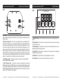
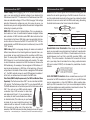
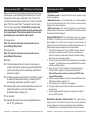
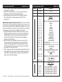
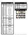
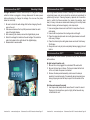
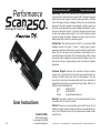
Performance
Intelligent Scanner
Performance Scan 250™
General Information
Unpacking: Thank you for purchasing the Performance Scan 250™
by American DJ®. Every Performance Scan 250™ has been thoroughly
tested and has been shipped in perfect operating condition. Carefully
check the shipping carton for damage that may have occurred during
shipping. If the carton appears to be damaged, carefully inspect your
fixture for any damage and be sure all equipment necessary to operate the unit has arrived intact. In the event damage has been found
or parts are missing, please contact our toll free customer support
number for further instructions. Please do not return this unit to your
dealer without first contacting customer support.
Introduction: The Performance Scan 250™ is a six channel DMX
intelligent scanner that uses 11 colors, 7 rotating gobo patterns,
(seperate wheels) and a 250w lamp to create a bright and colorful light
show. This unit can also run as a stand alone, sound-active unit, or
in a Master/Slave configuration. The Performance Scan 250™ comes
with several built in programs and is best used in multiples of four. For
best results use fog or special effects smoke to enhance the beams
projections.
Customer Support: American DJ® provides a toll free customer
support line, to provide help and to answer any question should you
encounter problems during your set up or initial operation. You may
also visit us on the web at www.americandj.com for any comments or
suggestions. Service Hours are Monday through Friday 9:00 a.m. to
5:00 p.m. Pacific Standard Time.
Voice:
(800) 322-6337
Fax:
(323) 582-2610
E-mail:
[email protected]
User Instructions
American DJ®
7/05
4295 Charter Street
Los Angeles CA. 90058
www.americandj.com
Warning! To prevent or reduce the risk of electrical shock or fire, do
not expose this unit to rain or moisture.
Caution! There are no user serviceable parts inside this unit. Do not
attempt any repairs yourself, doing so will void your manufactures warranty. In the unlikely event your unit may require service please contact
American DJ®.
American DJ® - www.americandj.com - Performance Scan 250™ Instruction Manual Page 2
Performance Scan 250™
General Instructions
To optimize the performance of this product, please read these operating
instructions carefully to familiarize yourself with the basic operations of
this unit. These instructions contain important safety information regarding the use and maintenance of this unit. Please keep this manual with
the unit, for future reference.
Performance Scan 250™
Product Registration
The Performance Scan 250™ carries a one year limited warranty.
Please fill out the enclosed warranty card to validate your purchase.
All returned service items whether under warranty or not, must be
freight pre-paid and accompany a return authorization (R.A.) number.
The R.A. number must be clearly written on the outside of the return
package. A brief description of the problem as well as the R.A. number must also be written down on a piece of paper included in the
shipping carton. If the unit is under warranty, you must provide a copy
of your proof of purchase invoice. You may obtain a R.A. number by
contacting our customer support team on our toll free customer support number. All packages returned to the service department not displaying a R.A. number on the outside of the package will be returned
to the shipper.
Performance Scan 250™
•
•
•
•
•
•
•
•
•
•
•
•
Features
Micro-Stepping Motors for Smooth Color and Gobo Transitions
DMX-512 Protocol Compatible (Uses four DMX Channels)
Selectable 110v/60Hz or 230v/50Hz
6 Rotating Gobo Patterns Plus Spot
9 Colors Plus White
Master/Slave Operation
Internal Microphone
Variable Speed Strobe Function
Gobo Shake
LED Display Menu
ZB-EHJ5 24v/250w Long Life Lamp
1 Year Warranty
American DJ® - www.americandj.com - Performance Scan 250™ Instruction Manual Page 3
Performance Scan 250™
Safety Precautions
• To reduce the risk of electrical shock or fire, do not expose this unit
rain or moisture
• Do not spill water or other liquids into or on to your unit.
• Be sure that the local power outlet match that of the required voltage for your unit.
• Do not attempt to operate this unit if the power cord has been
frayed or broken.
• Do not attempt to remove or break off the ground prong from
the electrical cord. This prong is used to reduce the risk of electrical
shock and fire in case of an internal short.
• Disconnect from main power before making any type of connection.
• Do not remove the cover under any conditions. There are no user
serviceable parts inside.
• Never operate this unit when it’s cover is removed.
• Never plug this unit in to a dimmer pack
• Always be sure to mount this unit in an area that will allow proper
ventilation. Allow about 6” (15cm) between this device and a wall.
• Do not attempt to operate this unit, if it becomes damaged.
• This unit is intended for indoor use only, use of this product outdoors voids all warranties.
• During long periods of non-use, disconnect the unit’s main power.
• Always mount this unit in safe and stable matter.
• Power-supply cords should be routed so that they are not likely to
be walked on or pinched by items placed upon or against them,
paying particular attention to cords at plugs, convenience receptacles, and the point where they exit from the appliance.
• Cleaning -The fixture should be cleaned only as recommended by
the manufacturer. See page 16 for cleaning details.
• Heat -The appliance should be situated away from heat sources
such as radiators, heat registers, stoves, or other appliances
(including amplifiers) that produce heat.
• The fixture should be serviced by qualified service personnel when:
A. The power-supply cord or the plug has been damaged.
B. Objects have fallen, or liquid has been spilled into the appliance.
C. The appliance has been exposed to rain or water.
D. The appliance does not appear to operate normally or exhibits a
marked change in performance.
American DJ® - www.americandj.com - Performance Scan 250™ Instruction Manual Page 4
Performance Scan 250™
Controls and Functions
TOP
4
Performance Scan 250™
LED
Digital Display
Control board
1
3
2
1. Breaker - A 5A built-in safety breaker to reduce the risk of electrical
shock or fire and protect the circuitry. In the case of a internal short or
power surge.
1
ENTER
DOWN
UP
NO
YES
2
3
4
5
6
1. Digital Display - This display shows the menu and operating functions.
2. Power Cord Inlet - This unit is equipped with a removable I.E.C.
power cord. Be sure to only use the power cord included with the
unit, this cord is designed to match the electrical requirements of the
unit. Other cords may cause the unit to overheat or malfunction. Voltage may vary from venue to venue, when connecting this unit to a
power supply be sure to connect to a matching power outlet. Never
use this fixture if the ground prong has been removed or broken off.
The ground prong is designed to reduce the risk of fire or electrical
shock in the event the unit suffers from an internal short.
2. Enter Button - This button is used confirm a function when working
in the system menu.
3. XLR Input Jack - This jack is used to accept an incoming DMX
signal or Master/Slave signal.
6. Yes Button - This button is used to select a function.
3. Down Button - This button is used to scroll backwards when navigating through the system menu.
4. Up Button - This button is used to scroll forward when navigating
through the system menu.
5. No Button - This button is used to deselect a function.
4. XLR Output Jack - This jack is used to transmit the incoming
DMX signal to another DMX fixture, or transmit a Master/Slave signal
to the next Performance Scan 250™ in the chain. For best results in
DMX or Master/Slave mode terminate this jack if it is the last unit in the
chain. See “Terminator” on page 8.
American DJ® - www.americandj.com - Performance Scan 250™ Instruction Manual Page 5
American DJ® - www.americandj.com - Performance Scan 250™ Instruction Manual Page 6
POWER
POWER
Performance Scan 250™
Set Up
Performance Scan 250™
Power Supply: Before plugging your unit in, be sure the source voltage in your area matches the selected voltage of your American DJ®
Performance Scan 250.™ The American DJ® Performance Scan 250™
has a user selectable voltage of 110v or 230v. See page 16 for voltage
selection. Because line voltage may vary from venue to venue, you
should be sure your unit voltage matches the wall outlet voltage before
attempting to operate you fixture.
DMX-512: DMX is short for Digital Multiplex. This is a universal protocol used as a form of communication between intelligent fixtures
and controllers. A DMX controller sends DMX data instructions from
the controller to the fixture. DMX data is sent as serial data that travels from fixture to fixture via the DATA “IN” and DATA “OUT” XLR terminals located on all DMX fixtures (most controllers only have a DATA
“OUT” terminal).
DMX Linking: DMX is a language allowing all makes and models of
DMX512
different manufactures to be linked together and
operate
from a sinDMX+,DMX-,COMMON
gle controller, as long as all fixtures and the controller are DMX compliant. To ensure proper DMX data transmission, when using several
DMX fixtures try to use the shortest cable path possible. The order
in which fixtures are connected in a DMX line does not influence the
DMX addressing. For example; a fixture assigned a DMX address
of 1
COMMON
may be placed anywhere in a DMX line, at theDMX512
beginning,
at theDMX
end,
+
OUT
3-PIN XLR
DMX or anywhere in the middle. When a fixture is assigned
a DMX address
of 1, the DMX controller knows to send DATA assigned to address 1
to that unit, no matter where it is located in the DMX chain.
Data Cable (DMX Cable) Requirements (For DMX and Master/Slave
Operation): The Performance Scan 250™ can be controlled via DMX512 protocol. The Performance Scan 250™ is a six channel DMX unit.
The DMX address is set on the bottom panel of the Performance Scan
250.™ Your unit and your DMX controller require
a standard 3-pin XLR connector for data input
and data output (Figure 1). If you are making your
own cables, be sure to use standard two conductor shielded cable (This cable may be purchased
at almost all pro sound and lighting stores). Your
cables should be made with a male and female
XLR connector on either end of the cable. Also
Figure 1
remember that DMX cable must be daisy chained and can not be split.
SOUND
REMOTE
CONTROL
INPUT
INPUT
OUTPUT
Notice: Be sure
toDMX512
follow figures two and three when making your own
DMX+,DMX-,COMMON
cables. Do not use the ground lug on the XLR connector. Do not connect the cable’s shield conductor to the ground lug or allow the shield
conductor to come in contact with the XLR’s outer casing. Grounding
the shield could cause a short circuit and erratic behavior.
COMMON
2
REMOTE
CONTROL
INPUT
SOUND
3
American DJ® - www.americandj.com - Performance Scan 250™ Instruction Manual Page 7
1
DMX512 OUT
3-PIN XLR
INPUT
2
DMX +
3
3
DMX -
OUTPUT
1
2
XLR Female Socket
2 Cold
2 Cold
DMX512 IN
3-PIN XLR
REMOTE
CONTROL
INPUT
SOUND
XLR Male Socket
1 Ground
1 Ground
INPUT
3
OUTPUT
Figure 2
1
2
Termination redu
avoids signal tra
and interference.
to connect a DMX
120 Ohm 1/4 W)
and PIN 3 (DMX
XLR Pin Configuration
Pin 1 = Ground
Pin 2 = Data Compliment (negative)
3 Hot
Figure 3
POWER
1
Set Up
3 Hot
Pin 3 = Data True (positive)
POWER
POWER
Special Note: Line Termination. When longer runs of cable are
3
1
2
used, you may need to use a terminator on the last unit to avoid erratic
behavior. A terminator is a 90-120 ohm 1/4 watt resistor which is connected between pins 2 and 3 of a male XLR connector (DATA + and
DATA -). This unit is inserted in the female XLR connector of the last
unit in your daisy chain to terminate the line. Using a cable terminator
(ADJ part number Z-DMX/T) will decrease the possibilities of erratic
behavior.
Termination reduces signal errors and
DMX512 IN
3-PIN XLR
3
avoids signal transmission problems
and interference. It is always advisable
to connect a DMX terminal, (Resistance
120 Ohm 1/4 W) between PIN 2 (DMX-)
and PIN 3 (DMX +) of the last fixture.
1
2
Figure 4
5-Pin XLR DMX Connectors. Some manufactures use 5-pin XLR
connectors for DATA transmission in place of 3-pin. 5-pin XLR fixtures
may be implemented in a 3-pin XLR DMX line. When inserting standard 5-pin XLR connectors in to a 3-pin line a cable adaptor must be
used, these adaptors are readily available at most electric stores. The
chart below details a proper cable conversion.
3-Pin XLR to 5-Pin XLR Conversion
Conductor
3-Pin XLR Female (Out)
5-Pin XLR Male (In)
Ground/Shield
Pin 1
Pin 1
Data Compliment (- signal)
Pin 2
Pin 2
Data True (+ signal)
Pin 3
Pin 3
Not Used
Pin 4 - Do Not Use
Not Used
Pin 5 - Do Not Use
American DJ® - www.americandj.com - Performance Scan 250™ Instruction Manual Page 8
Performance Scan 250™
LED Readouts and Functions
Below is a list of the LED readouts and their funtions that you
will see when you scroll through the function menu. To scroll
through the function menu, press either “Up” or “Down” till
you find the function that you want to use. To select a function
press “Yes” then press “Enter”. To deselect a function press
“No” and then press “Enter”. Notice: When a function has
been selected and activated, make sure the previous selection is deactivated. If the previous selection has not been
deactivated, your new selection will not work.
F1 - Reverse Pan
Note: This function will only work, when units are connected Master/Slave mode.
F2 - Reverse Tilt
Note: This function will only work, when units are connected Master/Slave mode.
F3 - Reset
F4 - This function allows the unit to react to low frequency
sounds. This function can also be used with master/slave
mode, by activating both F4 and following master/slave
operation on page 11.
F5 - Activates a preset, internal program. This function can also
be used with master/slave mode, by activating both F5
and following master/slave operation on page 11.
F6 - Selecting this function activates Master/Slave mode, and
selects that particular unit to be the Master unit.
(See Master/Slave mode page 11.)
F7 - No Function
F8 - Selecting the function will cause the Digital Readout on
LED to “flip” upside down.
American DJ® - www.americandj.com - Performance Scan 250™ Instruction Manual Page 9
Performance Scan 250™
Operation
Operating Modes:
• Stand alone mode - The unit will react to sound, chasing through
the built-in programs.
• Master/Slave mode - You can daisy chain up to 16 units together
to get a synchronized light show that will react to sound chasing
through several built in programs.
• DMX control mode - This function will allow you to control each
individual fixtures traits with a standard DMX-512 controller such as
the American DJ Show Designer.™
Universal DMX Control: This function allows you to use a universal DMX-512 controller such as the ©Elation® DMX Operator™ or
Show Designer™ to control mirror movement, the color wheel, the
gobo wheel, and the shutter (strobe). A DMX controller allows you to
create unique programs tailored to your individual needs.
1. The Performance Scan 250™ uses six DMX channels. Channel 1
controls pan, channel 2 controls tilt, channel 3 controls color,
channel 4 controls the gobo wheel, channel 5 controls strobing,
and channel 6 controls gobo rotation.
2. To control your fixture in DMX mode, follow the set-up procedures
on pages 7 - 8 as well as the set-up specifications that are included with your DMX controller.
3. Using the “Up” or “Down” buttons, Scroll through the function
LED until “A001” appears in the display, and press “Enter”.
Note: All other menu functions must be turned “OFF” when
using a DMX controller.
4. Use the controller’s faders to control the various DMX fixture traits.
DMX traits are listed on pages 12-13.
5. This will allow you to create your own programs.
6. For longer cable runs (more than a 100 feet) use a terminator on
the last fixture.
7. For help operating in DMX mode consult the manual included
with your DMX controller.
Stand-Alone Operation (Sound Active): This mode allows a
single unit to run to the beat of the music. Only use this mode when
running a single unit, or when running several units as individuals.
1. To activate this unit in stand-alone, sound active mode, use the
American DJ® - www.americandj.com - Performance Scan 250™ Instruction Manual Page 10
Performance Scan 250™
Operation cont.
“Up” or “Down” buttons to scroll through the function LED until
F4 appears in the display.
2. Press “Yes” then press “Enter”. The unit will react to the low
frequencies of music via the internal microphone.
3. To deactivate sound active mode, scroll through the function
LED until F4 appears in the display, and press “No” then
press “Enter”.
Performance Scan 250™
Channel
Value
Function
1
0 - 255
PAN
2
0 - 255
TILT
3
0 - 128
0-5
5-0
0-9
10 - 20
21 - 31
32 - 41
42 - 52
53 - 63
64 - 73
74 - 84
85 - 95
96 - 105
106 - 116
117 - 128
129 - 189
190
191 - 220
Master-Slave Operation (Sound Active): This function will allow
you to link up to 16 units together and operate without a controller. The
units will be sound activated. In Master-Slave operation one unit will
act as the controlling unit and the others will react to the controlling
units programs. Any unit can act as a Master or as a Slave.
1. Using standard XLR microphone cables, daisy chain your units
together via the XLR connector on the rear of the units. Remember the Male XLR connector is the input and the Female XLR
connector is the output. For longer cable runs we suggest a
terminator at the last fixture.
2. Select one light to be the Master. On that unit, use the “Up” or
“Down” buttons to scroll through the function menu until F6 is
read on the LED display. Press “Yes” then press “Enter”. Now,
scroll through the function menu until F4 is read on the LED display. Press “Yes” then press “Enter”.
3. Then, simply daisy chain the units together using XLR cables. The
slave units do not need to be set. Be sure that the slave units are
set to “A001”, and press “Enter” on each unit, they will fall into
place once they receive the signal.
221 - 222
223 - 252
253 - 255
4
COLOR
BLACKOUT
LAMP OFF WITHIN 40-60 SECONDS
WHITE
RED
BLUE
GREEN
YELLOW
MAGENTA
TURQUOISE
ORANGE
PURPLE (UV)
LIME GREEN
4 COLOR SPLIT (YELLOW, RED, GREEN, AND BLUE)
2 COLOR SPLIT (MAGENTA AND TURQUOISE)
COLOR MIX
WHITE
CLOCKWISE RAINBOW EFFECT
FAST
SLOW
STOP
COUNTER-CLOCKWISE RAINBOW
SLOW
FAST
SOUND ACTIVE
GOBO WHEEL
0 - 15
16 - 31
32 - 47
48 - 63
64 - 79
American DJ® - www.americandj.com - Performance Scan 250™ Instruction Manual Page 11
DMX Traits
OPEN
ROTATING GOBO 1 (GLASS)
ROTATING GOBO 2 (METAL)
ROTATING GOBO 3 (METAL)
ROTATING GOBO 4 (METAL)
American DJ® - www.americandj.com - Performance Scan 250™ Instruction Manual Page 12
Performance Scan 250™
DMX Traits
Performance Scan 250™
Channel
Value
Function
Channel
Value
4
80 - 95
96 - 111
112 - 127
128 - 132
133 - 144
145 - 156
157 - 168
169 - 180
181 - 192
193 - 204
205 - 217
218 - 219
220 - 249
ROTATING GOBO 5 (METAL)
ROTATING GOBO 6 (METAL)
ROTATING GOBO 7 (METAL)
STOP
GOBO 1 SHAKE
GOBO 2 SHAKE
GOBO 3 SHAKE
GOBO 4 SHAKE
GOBO 5 SHAKE
GOBO 6 SHAKE
GOBO 7 SHAKE
OPEN
CONTINUOUS WHEEL ROTATION
SLOW
FAST
SOUND ACTIVE
6
128 - 191
250 - 255
5
GOBO ROTATION
0 - 127
128 - 189
190 - 193
194 - 255
6
DMX Traits
Function
PULSE STROBE IN SEQUENCE
SLOW
FAST
192 - 223
NO FUNCTION (SHUTTER OPEN)
224 - 255 INTENSITY ADJUSTMENT 0% 100%
Performance Scan 250™
SPOT
GOBO 1
GOBO 4
GOBO 5
Gobos
GOBO 2
GOBO 6
GOBO 3
GOBO 7
GOBO INDEX
FORWARD ROTATION
FAST
SLOW
NO ROTATION
BACKWARD ROTATION
SLOW
FAST
SHUTTER, STROBE
0-5
6 - 60
61 - 63
64 - 95
96 - 100
101 - 127
LAMP OFF
STROBE EFFECT (8 FLASHES MAX
PER SECOND)
SLOW
FAST
NO FUNCTION (SHUTTER OPEN)
RESET
NO FUNCTION (SHUTTER OPEN)
SOUND ACTIVE STROBE
American DJ® - www.americandj.com - Performance Scan 250™ Instruction Manual Page 13
American DJ® - www.americandj.com - Performance Scan 250™ Instruction Manual Page 14
Performance Scan 250™
Lamp Replacement
This fixture is fitted with halogen lamps which are
highly susceptible to damage if improperly handled. Never touch the lamps with your bare fingers
as the oil from your hands will shorten lamp life.
Also, never move the fixture until the lamps have
had ample time to cool. Remember, lamps are not
covered under warranty conditions.
Caution: Always replace with the exact same type lamp, unless otherwise specified by an authorized American DJ® service technician.
Replacing with anything other than the specified part can damage
your unit and will void your manufactures warranty.
Warning: If you continue to blow lamps or the fuse, STOP using the
unit. Contact customer support for further instructions, you may have
to return the unit for servicing. Continuing to use the unit may cause
serious damage.
Lamp Replacement: Caution! Never attempt to change the lamp
while the fixture is plugged in. Always disconnect the main power
and allow the unit ample time to cool before attempting to replace
the lamp. Lamp replacement has been made simple by incorporating
the use of a slide out lamp socket assembly that is retained by thumb
screws.
1. Be sure to follow the proper handling procedures that deal with
discharge lamps.
2. Unscrew and remove the two thumb screws at the rear of the
unit.
3. After removing the thumb screws, slide the lamp socket assembly
out.
4. Carefully remove the old lamp.
5. Replace the lamp with an exact match and reassemble in reverse
order.
American DJ® - www.americandj.com - Performance Scan 250™ Instruction Manual Page 15
Performance Scan 250™
Lamp Optimization
Optimizing Lamp Alignment: This procedure centers the lamp in the
reflector. Proper optimization will increase lamp life and ensure a bright
crisp output. Improper optimization may add a yellow tint to the lamp
output and reduce intensity.
1. Be sure main power is disconnected and allow the unit to cool. If
the you have just installed a new unit you can obviously skip this
step.
2. Make a preliminary adjustment: Turn the three lamp adjustment
thumb screws completely in (clockwise). Then back them each
out (counter-clockwise) about three complete turns.
3. Turn the unit on and allow it to reset.
4. Using either a DMX controller or the control panel on the unit,
strike the lamp and focus the light on a flat surface.
6. Center the hot-spot (the brightest part of the beam) using the 3
adjustment screws (A,B,and C). Turn one screw at a time to drag
the hot-spot diagonally across the projected image. If you
cannot detect a hot-spot, adjust the lamp until the light is even.
7. To reduce a hot-spot, pull the lamp in by turning all three screws
clockwise 1/4-turn at a time until the light is evenly distributed.
8. If the light is brighter around the edge than it is in the center, or if
light output is low, the lamp is too far back in the reflector. “Push”
the lamp out by turning the screws.
Performance Scan 250™
Breaker Reset
This unit is equipped with a built-in safety breaker. This breaker is
designed to close the power circuit in the event of an internal short
or power surge. This will reduce the risk of electrical shock or fire and
protect the circuitry. To reset the breaker, push the breaker button in
until you hear it “pop” back in to place. If the breaker continues to
pop, stop using the unit and contact our customer support team, the
unit may need to be returned for service.
American DJ® - www.americandj.com - Performance Scan 250™ Instruction Manual Page 16
Performance Scan 250™
Selecting Voltage
Voltage Selection: Caution! Never attempt to change the voltage
while the fixture is plugged in. Always disconnect the main power
before attempting to change the voltage. You can see the photo
below for more help.
1. Be sure to check the wall voltage, first before changing the voltage on the unit.
2. Unscrew and remove the four phillips screws located on each
side of the digital display.
3. After removing the screws, remove the digital display cover.
4. Select the voltage that matches the wall voltage. The selection
switch is located on the right side of the digital display.
5. Reassemble in reverse order.
Performance Scan 250™
Fixture Cleaning
Due to fog residue, smoke, and dust, cleaning the internal and external optical lenses and mirror should be carried out periodically to
optimize light output. Cleaning frequency depends on the environment in which the fixture operates (I.e. smoke, fog residue, dust,
dew). In heavy club use we recommend cleaning on a monthly basis.
Periodic cleaning will ensure longevity, and crisp output.
1. Use normal glass cleaner and a soft cloth to wipe down the outside casing.
2. Use a brush to wipe down the cooling vents and fan grill.
3. Clean the external optics and mirror with glass cleaner and a soft
cloth every 20 days.
4. Clean the internal optics with glass cleaner and a soft cloth every
30-60 days.
5. Always be sure to dry all parts completely before plugging the unit
back in.
Performance Scan 250™
Trouble Shooting
Listed below are a few common problems that you may encounter,
with solutions.
No light output from the unit;
1. Be sure the unit is plugged into a standard 120v wall outlet.
2. Be sure the fuse has not blown. The fuse is located at the front
of the unit, inside the power cord socket.
3. Remove the lamp socket assembly and be sure the lamp is
seated in its socket properly. Occasionally lamps become loose
during shipping be sure the lamp is push in to its socket all the
way.
Unit does not respond to sound;
1. Low frequencies (bass) should cause the unit to react to sound.
Tapping on the microphone, quiet or high pitched sounds may
not activate the unit.
American DJ® - www.americandj.com - Performance Scan 250™ Instruction Manual Page 17
American DJ® - www.americandj.com - Performance Scan 250™ Instruction Manual Page 18
Performance Scan 250™
Warranty
1-YEAR LIMITED WARRANTY
A. American DJs® hereby warrants, to the original purchaser, American DJs® products to be free of manufacturing defects in material and workmanship for a period of
one year (365 days) from the date of purchase. This warranty shall be valid only if the
product is purchased within the United States of America, including possessions and
territories. It is the owner’s responsibility to establish the date and place of purchase
by acceptable evidence, at the time service is sought.
B. For warranty service, send the product only to the American DJs® factory. All shipping charges must be pre-paid. If the requested repairs or service (including parts
replacement) are within the terms of this warranty, American DJs® will pay return
shipping charges only to a designated point within the United States. If the entire
instrument is sent, it must be shipped in its original package. No accessories should
be shipped with the product. If any accessories are shipped with the product, American DJs® shall have no liability whatsoever for loss of or damage to any such accessories, nor for the safe return thereof.
C. This warranty is void if the serial number has been altered or removed; if the
product is modified in any manner which American DJs® concludes, after inspection,
affects the reliability of the product; if the product has been repaired or serviced by
anyone other than the American DJs® factory unless prior written authorization was
issued to purchaser by American DJs®; if the product is damaged because not properly maintained as set forth in the instruction manual.
D. This is not a service contract, and this warranty does not include maintenance,
cleaning or periodic check-up. During the period specified above, American DJs®
will replace defective parts at its expense, and will absorb all expenses for warranty
service and repair labor by reason of defects in material or workmanship. The sole
responsibility of American DJs® under this warranty shall be limited to the repair of
the product, or replacement thereof, including parts, at the sole discretion of American DJs®. All products covered by this warranty were manufactured after January 1,
1990, and bear identifying marks to that effect.
Performance Scan 250™
Model:
Voltage*:
Lamp:
Dimensions:
Colors:
Gobos:
Weight:
Breaker:
Duty Cycle:
DMX:
Sound Active:
Working Position:
Warranty:
Gobo Size:
Gobo Viewable:
Specifications
Performance Scan 250™
Selectable 110v/60Hz or
230v/50Hz
ZB-EHJ5 24v/250w
10.25”(L) x 11.75”(W) x 25.5”(H)
260mm x 299mm x 650mm
9 Plus White
6 Plus Spot
24 Lbs./ 11 Kgs.
5A
None
6 Channels
Yes
Any Safe, Secure Position
1 Year (365 days)
28mm
23mm
*Voltage is user selectable
Please Note: Specifications and improvements in the design
of this unit and this manual are subject to change without any
prior written notice.
E. American DJs® reserves the right to make changes in design and/or improvements
upon its products without any obligation to include these changes in any products
theretofore manufactured.
F. No warranty, whether expressed or implied, is given or made with respect to any
accessory supplied with products described above. Except to the extent prohibited
by applicable law, all implied warranties made by American DJs® in connection with
this product, including warranties of merchantability or fitness, are limited in duration to the warranty period set forth above. And no warranties, whether expressed or
implied, including warranties of merchantability or fitness, shall apply to this product
after said period has expired. The consumer’s and or Dealer’s sole remedy shall be
such repair or replacement as is expressly provided above; and under no circumstances shall American DJs® be liable for any loss or damage, direct or consequential, arising out of the use of, or inability to use, this product.
G. This warranty is the only written warranty applicable to American DJs® Products
and supersedes all prior warranties and written descriptions of warranty terms and
conditions heretofore published.
American DJ® - www.americandj.com - Performance Scan 250™ Instruction Manual Page 19
©American DJ Supply
American DJ World Headquarters:
4295 Charter Street Los Angeles, CA 90058 USA
Tel: 323-582-2650 / Fax: 323-582-2610
Web: www.americandj.com / E-mail: [email protected]