1
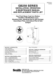
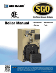
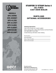
McDonnell & Miller
Installation & Maintenance
Instructions
MM-323
Series WFE Uni-Match®
Electric Water Feeder
Applications:
For use on boilers with mechanical (float type) or
electronic (probe type) LWCO's.
UAL
MAN D
FEE
D
FEETOR
ICA
The Uni-Match® water feeder is available in either 24 or
120 volt and all models feature a manual feed button.
Field selectable dwell/feed cycles allow condensate to
return to the boiler before feeding, lessening the chance
the boiler will be overfed or flood.
IND
Uni-Match
WARNING
CAU
TION
• Before using this product, read and understand instructions.
NG
WARNI
• Save these instructions for future reference.
• All work must be performed by qualified personnel trained in the proper application, installlation, and maintenance of plumbing, steam, and electrical equipment and/or systems in
accordance with all applicable codes and ordinances.
• To prevent electrical shock, turn off the electrical power before making electrical connections.
• Boiler manufacturer schematics should always be followed. In the event that the boiler
manufacturer’s schematic does not exist, or is not available from the boiler manufacturer,
refer to the schematics provided in this document.
• To prevent water damage check to make sure there is adequate floor drainage capacity.
Check all components in the system to insure that they will not leak in the event of an
overfeed condition.
• After installation, check for proper operation of all of the limit and operating controls,
before leaving the site.
Failure to follow this warning could cause property damage, personal injury or death.
SPECIFICATIONS
Maximum Water Pressure:
150 psi (10.5 kg/cm2)
Maximum Boiler Pressure:
15 psi (1 kg/cm2)
Pipe Connections:
3/8" NPT (sweat adapters included for connection
to 1/2" copper pipe)
Flow Data:
2 gpm (7.6 lpm) standard
Orifices included to change feed rate to 1 gpm
(3.8 lpm) or 4 gpm (15.1 lpm)
Electrical Ratings
Model
Voltage**
Power
Consumption*
WFE-24
WFE-120
24VAC
120VAC
15VA
20VA
* During Feed Cycle
** 50/60 Hz
Maximum Water Temperature:
175˚F (79˚C)
Maximum Ambient Temperature:
100˚F (38˚C)
Dwell/Feed Selector Switch
4
The water feeder has a DIP type switch block with
four on/off switches. Each switch has a specific
dwell/feed cycle which is activated upon receiving
a signal from the LWCO. The feeder will be deactivated when the LWCO is satisfied or if the
dwell/feed period has been exceeded.
3
2
1
F
OF 1
SW
ON
Manual Feed
Manual
Feed
Button
There is a manual feed button which when pressed
will add water to the boiler.
Multi-Color LED
A multi-color LED indicates status during operation,
incorrect switch selection and when dwell/feed
cycle has been exceeded.
Multi
Function
LED
Dwell/Feed
Selector Switch
Dwell/Feed Cycle Limit
The feeder will stop feeding water whenever the
selected dwell/feed cycle time has been exceeded
and the LWCO is still sending a signal.
STEP 1 - Installation
1 a. Control must be installed within eyesight of boiler.
b. Clearance must be provided on all sides to
service control.
c. Unit must be installed in a horizontal pipe
in an upright position.
d. Arrow on feeder must point in the
direction of flow into the boiler.
e. Install isolation valves and unions on the
inlet and outlet piping for easier trouble
shooting and repair/replacement.
f. Install manual fill valve and bypass line for
removal while the boiler is in service.
2. Water feeders are shipped from the factory equipped
for a 2 gpm feed rate. A separate kit with instruction
sheet and field installable orifices for 1 gpm and 4 gpm
feed rates is included. If the alternate feed rates are
required, refer to the instruction sheet provided with the
kit for orifice replacement.
2
WATER FEEDER
CITY
WATER SUPPLY
INLET
VALVE
CHECK
VALVE
BYPASS
VALVE
UNION
STRAINER
OUTLET
VALVE
UNION
UNION
BYPASS
CONNECT TO
RETURN HEADER
ON BOILER
1 GPM
Orifice
4 GPM
Orifice
STEP 2 - Electrical Installation
WARNING
IMPORTANT
To prevent electrical shock, turn off the
electrical power before making electrical
connections.
Failure to follow this warning could cause
property damage, personal injury or death.
Boiler manufacturer schematics should be followed. In
the event that the boiler manufacturer's schematic does
not exist, or is not available from the boiler manufacturer,
refer to the schematics provided in this document.
Terminal Connections
For all wire connections to the terminal block (M).
1. Strip about 1/3" (8.5 mm) of insulation from the wire.
2. Loosen the terminal screw (N) but DO NOT
REMOVE. Move the wire clamping plate (P) back
until the plate touches the back side of the screw head.
3. Insert the stripped end of the wire under the wire
clamping plate (P) and securely tighten the
terminal screw (N).
Unless otherwise noted, water feeder voltage should be
the same as the LWCO and burner circuit voltage.
NOTE
NOTE
Before wiring water feeder, operate boiler and check all
safety devices.
P
M
NOTE
WARNING
Do not use automatic water feeders with manual reset
LWCO's. Failure to follow this warning could cause
flooding, property damage, personal injury or death.
N
Wire must be 18 AWG (min) or as required by local code.
Wire insulation rating must be at least 167˚F (75˚C)
Wiring Diagram Selection Chart
Based on the water feeder and low water cut-off combination you are installing, select proper wiring
diagram and proceed to that page.
Feeder Model
WFE-24
WFE-24
WFE-24
WFE-24
WFE-24
WFE-120
WFE-120
WFE-120
WFE-120
WFE-120
WFE-24
WFE-24
WFE-120
WFE-120
WFE-120
WFE-24
WFE-120
WFE-24
WFE-120
LWCO Model
PS-802 with burner wiring harness
PS-802 with burner terminal connections
67 w/24 volt burner circuit
67 w/120 volt burner circuit
67G (millivolt burner circuit)
PS-801 with numbered terminals
PS-801 with lettered terminals
67 w/24 volt burner circuit
67 w/120 volt burner circuit
67G (millivolt burner circuit)
Hydrolevel 400
Hydrolevel CG400
Hydrolevel 450
Hydrolevel CG450
Hydrolevel CGT450
Honeywell LWCO (24 volt)
Honeywell LWCO (120 volt)
TACO LWCO (24 volt)
TACO LWCO (120 volt)
Diagram Number
1
1
4
6
9
2
3
7
5
8
10
11
12
13
14
15
16
18
17
Page
4
4
4
4
5
4
4
4
4
5
5
5
5
5
6
6
6
6
6
3
Diagram 5
Wiring Diagram Legends
WFE-120 / 67 with 120 volt burner circuit
1.
Bold lines indicate action to be taken
in Step shown.
2.
Grey lines indicate existing wiring.
• Connect wire from terminal 'N' of water
feeder to 'Neutral' wire of burner circuit.
• Connect wire from terminal 'H' of water
feeder to terminal '2' on LWCO.
• Connect jumper wire connecting terminals
'2' and '3' of LWCO.
• Connect wire from terminal 'W' of
BURNER
water feeder to terminal '4' on LWCO.
Diagram 1
WFE-24 / PS-802-LWCO
• Connect wire from terminal 'N' of water
feeder to terminal ''N' on LWCO.
• Connect wire from terminal 'H' of water
feeder to terminal 'H' on LWCO.
• Connect wire from terminal 'W' of water
feeder to terminal 'W' on LWCO.
PS-802-24
LWCO
SERIES 67
LOW WATER
CUT-OFF
Factory
Jumper
Bar
H N B
1
3
NEUTRAL
120 VAC
HOT
2
4
N H C W B
UNI-MATCH
WATER FEEDER
WFE-120
W N H
UNI-MATCH
WATER FEEDER
WFE-24
W N H
Diagram 6
WFE-24 / 67 with 120 volt burner circuit
Diagram 2
WFE-120 / PS-801-LWCO with numbered terminals
• Connect wire from terminal 'N' of
water feeder to terminal '2' on LWCO.
• Connect wire from terminal 'H' of
water feeder to terminal '1' on LWCO.
• Connect wire from terminal 'W' of
water feeder to terminal '4' on LWCO.
Field or
Factory
Jumper
Wire
PS-801-120
LWCO
P 1
2
UNI-MATCH
WATER FEEDER
WFE-120
3
4
5
• Install wire from burner circuit 'Neutral' wire to the trans
former input 'Neutral' terminal.
• Install wire from burner circuit 'Hot' wire to the transformer
input 'Hot' terminal.
• Install wire from transformer output 'Neutral' terminal
to terminal 'N' on the water feeder.
• Install wire from terminal 'W' on the water feeder to terminal
'4' on the low water cut-off.
• Install wire from transformer output 'Hot' terminal to terminal
'H' on water feeder and terminal '3' on low water cut-off.
NOTE: Transformer provided by others.
W N H
BURNER
120 VAC
SUPPLY
NEUTRAL
120 VAC
HOT
Diagram 3
SERIES 67
LOW WATER
CUT-OFF
WFE-120 / PS-801-LWCO with lettered terminals
• Connect wire from terminal 'N' of
water feeder to terminal 'N' on LWCO.
• Connect wire from terminal 'H' of
water feeder to terminal 'H' on LWCO.
• Connect wire from terminal 'W' of
water feeder to terminal 'W' on LWCO.
PS-801-120
LWCO
Factory
Jumper
Bar
1
3
UNI-MATCH
WATER FEEDER
WFE-24
N H C W B
2
4
24V
TRANSFORMER
W N H
Diagram 7
UNI-MATCH
WATER FEEDER
WFE-120
WFE-120 / 67 with 24 volt burner circuit
W N H
Diagram 4
WFE-24 / 67 with 24 volt burner circuit
• Connect wire from terminal 'N' of
BURNER
water feeder to 'Neutral' wire of
SERIES 67
burner circuit.
1
2
LOW WATER
3
4
• Connect wire from terminal 'H' of CUT-OFF
water feeder to terminal '2' on
LWCO.
UNI-MATCH
WATER FEEDER
• Connect jumper wire connecting
W
WFE-24
terminals '2' and '3' of LWCO.
• Connect wire from terminal 'W' of
water feeder to terminal '4' on LWCO.
4
NEUTRAL
24 VAC
HOT
• Install wire from burner circuit 'Neutral' wire to terminal 'N'
on water feeder.
• Install wire from burner circuit 'Hot' wire to terminal 'H' on
water feeder and terminal '3' on low water cut-off.
• Install wire from terminal 'W' on the water feeder
to terminal '4' on the low water cut-off.
24V
TRANSFORMER
BURNER
NEUTRAL
120V
HOT
SERIES 67
LOW WATER
CUT-OFF
1
3
2
4
N H
UNI-MATCH
WATER FEEDER
W N H
WFE-120
Diagram 8
Diagram 11
WFE-120 / 67 with millivolt burner circuit
WFE-24 / Hydrolevel CG400
• Install wire from 120 volt circuit 'Neutral' wire to terminal 'N'
on water feeder.
• Install wire from 120 volt circuit 'Hot' wire to terminal 'H' on
water feeder and terminal '3' on low water cut-off.
• Install wire from terminal 'W' on the water feeder
to terminal '4' on the low water cut-off.
• Connect wire from terminal 'N' of water feeder
to terminal '2' on LWCO.
• Connect wire from terminal 'H' of water feeder
to terminal '1' on LWCO.
• Connect wire from terminal 'W' of water feeder
to terminal 'A' on LWCO.
MILLIVOLT
BURNER
CIRCUIT
SERIES 67
LOW WATER
CUT-OFF
1
3
HYDROLEVEL CG400
2
1
P1 P2 A BURNER
Factory
Jumper
Bar
2
4
NEUTRAL
HOT
120V
UNI-MATCH
WATER FEEDER
W N H
WFE-120
UNI-MATCH
WATER FEEDER
WFE-24
Diagram 9
W N H
WFE-24 / 67 with millivolt burner circuit
Diagram 12
• Install wire from 120 volt circuit 'Neutral' wire to
the transformer input 'Neutral' terminal.
• Install wire from 120 volt circuit 'Hot' wire to the
transformer input 'Hot' terminal.
• Install wire from transformer output 'Neutral'
terminal to terminal 'N' on the water feeder.
• Install wire from transformer output 'Hot' terminal
to terminal 'H' on water feeder and terminal '3' on
low water cut-off.
• Install wire from terminal 'W' on the water feeder
to terminal '4' on the low water cut-off.
NOTE: Transformer provided by others.
WFE-120 / Hydrolevel 450
• Connect wire from terminal 'N' of water feeder
to terminal '2' on LWCO.
• Connect wire from terminal 'H' of water feeder
to terminal '1' on LWCO.
• Connect wire from terminal 'W' of water feeder
to terminal 'A' on LWCO.
HYDROLEVEL 450
2
1 P1 P2 A
Factory
Jumper
Bar
SERIES 67
LOW WATER
CUT-OFF
1
3
HOT
NEUTRAL
120V
MILLIVOLT
BURNER
CIRCUIT
24V
2
4
TRANSFORMER
UNI-MATCH
WATER FEEDER
W N H
WFE-24
UNI-MATCH
WATER FEEDER
WFE-120
W N H
Diagram 13
Diagram 10
WFE-120 / Hydrolevel CG450
WFE-24 / Hydrolevel 400
• Connect wire from terminal 'N' of water feeder to terminal
'2' on LWCO.
• Connect wire from terminal 'H' of water feeder to terminal
'1' on LWCO.
• Connect wire from terminal 'W' of water feeder to terminal
'A' on LWCO.
HYDROLEVEL 400
2
1 P1 P 2 A
UNI-MATCH
WATER FEEDER
WFE-24
Factory
Jumper
Bar
• Connect wire from terminal 'N' of water feeder
to terminal '2' on LWCO.
• Connect wire from terminal 'H' of water feeder
to terminal '1' on LWCO.
• Connect wire from terminal 'W' of water feeder
to terminal 'A' on LWCO.
HYDROLEVEL CG450
2
1
P1 P2 A BURNER
Factory
Jumper
Bar
UNI-MATCH
WATER FEEDER
WFE-120
W N H
W N H
5
Diagram 14
Diagram 17
WFE-120 / Hydrolevel CGT450
WFE-120 / TACO LWCO (120 volt)
• Connect wire from terminal 'N' of water feeder
to terminal '2' on LWCO.
• Connect wire from terminal 'H' of water feeder
to terminal '1' on LWCO.
• Connect wire from terminal 'W' of water feeder
to terminal 'A' on LWCO.
Factory
Jumper
Bar
• Connect wire from terminal 'N' of water feeder
to terminal 'N' on LWCO.
• Connect wire from terminal 'H' of water feeder
to terminal 'L' on LWCO.
• Connect wire from terminal 'W' of water feeder
to terminal 'NO' on LWCO.
Field or
Factory
Installed
Jumper
Wire
HYDROLEVEL CGT450
2
1
P1
P2
UNI-MATCH
WATER FEEDER
WFE-120
LOW
A BURNER LIMIT
THERMOSTAT
UNI-MATCH
WATER FEEDER
MODEL
WFE-120
W N H
Diagram 15
Diagram 18
WFE-24 / Honeywell LWCO (24 volt)
WFE-24 / TACO LWCO (24 volt)
Field or
Factory
Installed
Jumper
Wire
HONEYWELL LWCO
24 VOLT
A
T2
B
A
UNI-MATCH
WATER FEEDER
MODEL
WFE-24
• Connect wire from terminal 'N' of water feeder
to terminal 'L2' on LWCO.
• Connect wire from terminal 'H' of water feeder
to terminal 'L1' on LWCO.
• Connect jumper wire from terminal 'L1' to
terminal 'A' on the low water cut-off.
• Connect wire from terminal 'W' of water feeder
to terminal 'A' on LWCO.
HONEYWELL LWCO
120 VOLT
A
L2
TACO LWCO
24 VOLT
NC COM NO L
UNI-MATCH
WATER FEEDER
MODEL
WFE-24
W N H
WF2-U-120 / Honeywell LWCO (120 volt)
B
A
UNI-MATCH
WATER FEEDER
WF2-U-120
W N H
6
W N H
N GND P
B
Diagram 16
L1
N GND P
• Connect wire from terminal 'N' of water feeder
to terminal 'N' on LWCO.
• Connect wire from terminal 'H' of water feeder
to terminal 'L' on LWCO.
• Connect wire from terminal 'W' of water feeder
to terminal 'NO' on LWCO.
• Connect wire from terminal 'N' of water feeder
to terminal 'T2' on LWCO.
• Connect wire from terminal 'H' of water feeder
to terminal 'T1' on LWCO.
• Connect jumper wire from terminal 'T1' to
terminal 'A' on the low water cut-off.
• Connect wire from terminal 'W' of water feeder
to terminal 'A' on LWCO.
T1
TACO LWCO
120 VOLT
NC COM NO L
B
W N H
STEP 3 - Testing
a. Open the inlet valve (X) and the outlet
valve (Y). Check for any leakage.
If there are any leaky connections, close
the inlet and outlet valves and correct
the problem.
b. Turn the boiler’s electric power on and fill
it to the manufacturer's recommended
normal water level by depressing the red
manual feed button (Z) on the water
feeder.
B
X
Z
UA L
MAN D
FEE
D
FEETOR
ICA
IND
Y
c. Check the water feeder (B) operation by performing the following steps:
1. Slowly drain water from the boiler.
2. The burner should turn off when the water level drops below the cut-off level of the LWCO, which
will activate the water feeder's delay feed cycle.
!
WARNING
If burner does not turn off when water level falls below level of LWCO, turn
off power to boiler and check operation of LWCO.
3. Feeder should turn on to feed water to boiler after delay period has expired.
NOTE: Delay period is determined by position of selector. Unit is shipped
with switch in Position 2. Refer to chart on page 8 for alternate settings.
4. Feeder will be deactivated when water level is restored to level as determined by LWCO.
NOTE: McDonnell & Miller Series PS LWCO's have a 15 second DOM (Delay on Make) to restore
water level in boiler to an appropriate level without overfeeding. Consult other manufacturer's LWCO
installation literature for DOM times.
5. Repeat steps to ensure feeder is operating satisfactorily.
Multi-Color LED
Upon receiving a signal from LWCO (power to terminal ‘W’) the multi-color LED will indicate the status
of the feeder.
LED
Condition
Solution
Flashing Green Dwell Period -Solenoid Closed
————
Solid Green
Feed Period -Solenoid Open
————
Flashing Red
Invalid Feed Cycle Switch Setting
Only one of the switches should be in the ‘ON’ position.
Solid Red
Dwell/Feed Cycle Exceeded
Check operation of LWCO.
7
McDonnell & Miller
STEP 3 - Testing
Dwell/Feed Switches
The unit is shipped with switch 2 ‘ON’ and all other switches on the ‘OFF’ position.
O
N
1
2
3
4
Factory Setting
Position 2 - ON
Switch
Position
Initial
Dwell*
Initial
Feed*
Dwell/Feed
Cycles
1
0
300
1
2
60
60
5
3
30
270
1
4
120
180
1
*Dwell/Feed Time in Seconds
Switch Selection Guidelines
#1 – Should only be used with a float type LWCO such as the M&M Series 67.
#2 – Satisfactory for most residential steam boiler applications.
#3 – Shorter initial dwell period suggested for smaller 3 or 4 section boilers.
#4 – Longer initial dwell period suggested for a period of time immediately after initial boiler installation.
STEP 4 - Troubleshooting
If the unit fails to feed water as required, perform the following diagnostic checks:
1. Recheck all wiring to ensure proper connections, as specified in these instructions.
2. Check to insure that the integral strainer is clean and free of debris and sediment.
3. Check to ensure proper operation of low water cut-off controls connected to water feeder.
MAINTENANCE
SCHEDULE:
• Inspect the water feeder annually. Replace it if it is worn, corroded, or if components no longer operate
properly.
• Replace the water feeder every 10 years. More frequent replacement may be required when severe
conditions exist such as rapid switch cycling and surging water levels.
• Disassemble and carefully clean strainer screen once per heating season.
ITT
8200 N. Austin Ave.
Morton Grove, IL 60053
tel: 847-966-3700
fax: 847-966-9052
www.mcdonnellmiller.com
©2008 ITT Corporation
Printed in U.S.A. 10-08 211163