1
HP ProLiant DL380 Generation 4 Server
Maintenance and Service Guide
May 2006 (Eighth Edition)
Part Number 359226-008
© Copyright 2004-2006 Hewlett-Packard Development Company, L.P.
The information contained herein is subject to change without notice. The only warranties for HP products and services are set forth in the express
warranty statements accompanying such products and services. Nothing herein should be construed as constituting an additional warranty. HP
shall not be liable for technical or editorial errors or omissions contained herein.
Microsoft, Windows, and Windows NT are U.S. registered trademarks of Microsoft Corporation.
Intel and Xeon are trademarks or registered trademarks of Intel Corporation or its subsidiaries in the United States and other countries.
Linux is a U.S. registered trademark of Linus Torvalds.
May 2006 (Eighth Edition)
Part Number 359226-008
Audience assumptions
This guide is for an experienced service technician. HP assumes you are qualified in the servicing of
computer equipment and trained in recognizing hazards in products with hazardous energy levels and
are familiar with weight and stability precautions for rack installations.
Contents
Illustrated parts catalog ................................................................................................................. 6
Customer self repair................................................................................................................................... 6
Mechanical components (SCSI model) ......................................................................................................... 7
System components (SCSI model) ................................................................................................................ 8
Mechanical components (SAS model) ........................................................................................................ 12
System components (SAS model) ............................................................................................................... 13
Removal and replacement procedures ........................................................................................... 17
Introduction ............................................................................................................................................ 17
Required tools......................................................................................................................................... 17
Safety considerations ............................................................................................................................... 17
Preventing electrostatic discharge .................................................................................................... 17
Server warnings and cautions ......................................................................................................... 17
Preparation procedures ............................................................................................................................ 18
Extend the server from the rack........................................................................................................ 19
Power down the server ................................................................................................................... 20
Remove the server from the rack ...................................................................................................... 20
Access the product rear panel ......................................................................................................... 21
Non-hot-plug procedures .......................................................................................................................... 22
Access panel ................................................................................................................................ 22
DVD/CD-ROM drive ...................................................................................................................... 22
DVD/CD-ROM drive ejector assembly.............................................................................................. 23
Diskette drive option ...................................................................................................................... 24
Front bezel ................................................................................................................................... 24
Front fan bracket ........................................................................................................................... 25
Rear fan bracket............................................................................................................................ 26
Battery-backed write cache procedures............................................................................................. 26
PCI riser cage door latch ................................................................................................................ 30
PCI riser cage ............................................................................................................................... 31
Expansion board ........................................................................................................................... 31
Expansion slot cover ...................................................................................................................... 32
Expansion board ejector/divider ..................................................................................................... 33
PCI slot release lever ...................................................................................................................... 34
PCI lightpipe and cover .................................................................................................................. 35
Power converter module ................................................................................................................. 36
Power button/LED board ................................................................................................................ 37
DIMMs......................................................................................................................................... 38
PPM............................................................................................................................................. 39
Processor...................................................................................................................................... 39
Battery ......................................................................................................................................... 41
System board................................................................................................................................ 42
Re-entering the server serial number and product ID ........................................................................... 43
Hot-plug procedures ................................................................................................................................ 44
Hot-plug SCSI hard drive ................................................................................................................ 44
SCSI hard drive blank .................................................................................................................... 44
Hot-plug SAS hard drive................................................................................................................. 45
SAS hard drive blank..................................................................................................................... 46
Universal hot-plug tape drive........................................................................................................... 46
Tape drive blank ........................................................................................................................... 47
Hot-plug power supply ................................................................................................................... 47
Contents
3
Power supply blank ....................................................................................................................... 48
Hot-plug fan.................................................................................................................................. 49
PCI Hot Plug expansion board ........................................................................................................ 50
PCI Hot Plug expansion slot cover.................................................................................................... 52
Cabling ..................................................................................................................................... 54
Cabling ................................................................................................................................................. 54
SAS model cabling.................................................................................................................................. 54
SAS hard drive cabling .................................................................................................................. 54
USB cabling.................................................................................................................................. 55
DVD/CD-ROM drive cabling........................................................................................................... 56
Diskette drive cabling..................................................................................................................... 56
Power button/LED cabling .............................................................................................................. 57
Optional PCI Hot Plug backplane cabling ......................................................................................... 57
RILOE II cabling............................................................................................................................. 58
Internal power cabling ................................................................................................................... 58
SCSI model cabling ................................................................................................................................. 58
Embedded simplex SCSI cabling ..................................................................................................... 59
Embedded duplex SCSI cabling ...................................................................................................... 59
PCI simplex SCSI cabling ............................................................................................................... 60
PCI duplex SCSI cabling................................................................................................................. 61
Mixed duplex SCSI cabling ............................................................................................................ 61
Installing the SCSI terminator board ................................................................................................. 63
Removing the SCSI terminator board................................................................................................ 63
USB cabling.................................................................................................................................. 64
DVD/CD-ROM drive cabling........................................................................................................... 65
Diskette drive cabling..................................................................................................................... 65
Power button/LED cabling .............................................................................................................. 66
Optional PCI Hot Plug backplane cabling ......................................................................................... 66
RILOE II cabling............................................................................................................................. 67
Internal power cabling ................................................................................................................... 67
External storage cabling ................................................................................................................. 68
Diagnostic tools .......................................................................................................................... 69
Troubleshooting resources ........................................................................................................................ 69
Array Diagnostic Utility ............................................................................................................................ 69
Automatic Server Recovery ....................................................................................................................... 69
HP Insight Diagnostics.............................................................................................................................. 70
Integrated Management Log ..................................................................................................................... 70
Survey Utility .......................................................................................................................................... 70
HP Systems Insight Manager ..................................................................................................................... 71
Lights Out Manager technology ................................................................................................................ 71
Option ROM Configuration for Arrays ....................................................................................................... 71
HP ProLiant Essentials Rapid Deployment Pack ............................................................................................ 71
HP ROM-Based Setup Utility ..................................................................................................................... 72
SmartStart software ................................................................................................................................. 72
ROMPaq utility.............................................................................................................................. 72
System Online ROM flash component utility ...................................................................................... 73
Component identification ............................................................................................................. 74
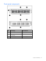
Front panel components ........................................................................................................................... 75
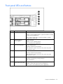
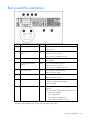
Front panel LEDs and buttons .................................................................................................................... 76
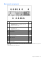
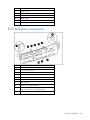
Rear panel components............................................................................................................................ 77
Rear panel LEDs and buttons..................................................................................................................... 78
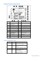
System board components........................................................................................................................ 79
Contents
4
System maintenance switch............................................................................................................. 79
NMI switch ................................................................................................................................... 80
Chassis ID switch........................................................................................................................... 80
DIMM slots ................................................................................................................................... 80
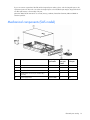
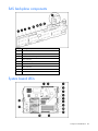
SCSI backplane components..................................................................................................................... 81
SAS backplane components ..................................................................................................................... 82
System board LEDs .................................................................................................................................. 82
System LEDs and internal health LED combinations....................................................................................... 83
SCSI backplane LEDs ............................................................................................................................... 85
Hot-plug SCSI hard drive LEDs .................................................................................................................. 85
Hot-plug SCSI hard drive LED combinations ................................................................................................ 86
Hot-plug SAS hard drive LEDs ................................................................................................................... 87
Hot-plug SAS hard drive LED combinations ................................................................................................. 87
PCI Hot Plug LED status combinations......................................................................................................... 88
PCI riser cage LED ................................................................................................................................... 89
Remote management connector................................................................................................................. 89
Internal PCI Hot Plug LEDs and button ........................................................................................................ 90
Identifying hot-plug fans ........................................................................................................................... 90
Hot-plug fan LED ..................................................................................................................................... 91
Power converter module LED..................................................................................................................... 92
Battery-backed write cache LEDs ............................................................................................................... 92
Battery-backed write cache LED statuses ..................................................................................................... 93
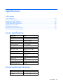
Specifications ............................................................................................................................. 94
Server specifications ................................................................................................................................ 94
Environmental specifications ..................................................................................................................... 94
Hot-plug power supply calculations............................................................................................................ 95
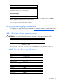
DDR2 SDRAM DIMM specifications ........................................................................................................... 95
1.44-MB diskette drive specifications ......................................................................................................... 95
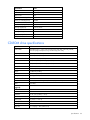
CD-ROM drive specifications .................................................................................................................... 96
DVD-ROM drive specifications .................................................................................................................. 97
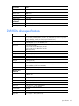
Ultra320 SCSI hard drive specifications ..................................................................................................... 98
SAS and SATA hard drive specifications .................................................................................................... 98
Acronyms and abbreviations........................................................................................................ 99
Index....................................................................................................................................... 102
Contents
5
Illustrated parts catalog
In this section
Customer self repair ................................................................................................................................. 6
Mechanical components (SCSI model) ........................................................................................................ 7
System components (SCSI model) ............................................................................................................... 8
Mechanical components (SAS model) ....................................................................................................... 12
System components (SAS model).............................................................................................................. 13
Customer self repair
What is customer self repair?
HP's customer self-repair program offers you the fastest service under either warranty or contract. It
enables HP to ship replacement parts directly to you so that you can replace them. Using this program,
you can replace parts at your own convenience.
A convenient, easy-to-use program:
•
An HP support specialist will diagnose and assess whether a replacement part is required to address
a system problem. The specialist will also determine whether you can replace the part.
•
Replacement parts are express-shipped. Most in-stock parts are shipped the very same day you
contact HP. You may be required to send the defective part back to HP, unless otherwise instructed.
•
Available for most HP products currently under warranty or contract. For information on the warranty
service, refer to the HP website
(http://h18004.www1.hp.com/products/servers/platforms/warranty/index.html).
For more information about HP's customer self-repair program, contact your local service provider. For the
North American program, refer to the HP website (http://www.hp.com/go/selfrepair).
Customer replaceable parts are identified in the following tables.
Illustrated parts catalog
6
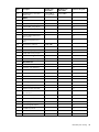
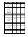
Mechanical components (SCSI model)
Item
Description
Original spare
part number
Modified
spare part
number
Customer
self repair
1
Access panel
359244-001
—
Yes
2
Front bezel
359245-001
—
Yes
3
Tape drive blank
367666-001
—
Yes
4
Hard drive blank
122759-001
—
Yes
5
Diskette drive slot cover (see "Plastics Kit,"
Item 28k)
—
—
6
Power supply blank
359246-001
—
Yes
Illustrated parts catalog
7
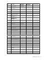
System components (SCSI model)
Item
Description
Original spare
part number
Modified spare
part number
Customer self repair
System components
7
Hot-plug fan, 60 mm
289544-001
—
Yes
8
Front fan bracket, 6 bay
371148-001
—
Yes
9
Rear fan bracket, 2 bay
289558-001
—
Yes
10
Hot-plug power supply, 400 W
338022-001‡
See requirement
406393-001
Yes
11
PCI riser cages
—
—
—
a) PCI riser cage, with non-hotplug PCI-X (standard)
359248-001‡
See requirement
411020-001
Yes
b) PCI riser cage, with non-hotplug PCI Express (optional)*
359259-001‡
See requirement
411021-001
Yes
c) PCI riser cage, with PCI-X
hot-plug (optional)*
359260-001‡
See requirement
411022-001
Yes
Processor assemblies
—
—
—
a) 3.0-GHz Intel® Xeon™
378006-001
—
Yes
374233-001
—
Yes
364757-001
—
Yes
364758-001
—
Yes
12
1-MB L2 cache* **
b) 3.2-GHz Intel® Xeon™
1-MB L2 cache* **
c) 3.4-GHz Intel® Xeon™
1-MB L2 cache* **
d) 3.6-GHz Intel® Xeon™
1-MB L2 cache* **
Illustrated parts catalog
8
Item
Description
Original spare
part number
Modified spare
part number
Customer self repair
e) 2.8-GHz Intel® Xeon™
399132-001
—
Yes
379427-001
—
Yes
399764-001
—
Yes
379428-001
—
Yes
379429-001
—
Yes
379430-001
—
Yes
399133-001
—
Yes
403934-001
—
Yes
2-MB L2 cache* **
f) 3.0-GHz Intel® Xeon™
2-MB L2 cache* **
g) 3.0-GHz Intel® Xeon™
2-MB L2 cache LV* **
h) 3.2-GHz Intel® Xeon™
2-MB L2 cache* **
i) 3.4-GHz Intel® Xeon™
2-MB L2 cache* **
j) 3.6-GHz Intel® Xeon™
2-MB L2 cache* **
k) 3.8-GHz Intel® Xeon™
2-MB L2 cache* **
l) 2.83-GHz Intel® Xeon™
dual core, 1066-MHz FSB, 4MB cache (for use with dualcore processor SCSI system
board assembly number
012863-001 only)* **
Boards
13
PPM, 12 V, 81 A
347884-001
—
Yes
14
Smart Array 6i memory module
351518-001
—
Yes
15
System board
—
—
—
a) System board, single-core
processor support, with
processor cages and system
battery
359251-001
—
Yes
b) System board, dual-core
processor support, SCSI, with
processor cages and system
battery (for use with Intel®
Xeon™ dual-core processor
only)*
404715-001‡
See requirement
411028-001
Yes
16
Power converter module
361667-001
—
Yes
17
SCSI backplane, 6 bay
359253-001‡
See requirement
411023-001
Yes
18
SCSI terminator
289563-001‡
See requirement
411025-001
Yes
19
Power button/LED board
366300-001‡ See
requirement
411026-001
Yes
Media devices
20
Diskette drive, slimline,
1.44 MB (optional)
289550-001‡
See requirement
399311-001
Yes
21
CD-ROM drive, removable
slimline, IDE, 24X
228508-001‡
See requirement
399401-001
Yes
Illustrated parts catalog
9
Item
Description
Original spare
part number
Modified spare
part number
Customer self repair
22
DVD-ROM drive, removable
slimline, 8X*
268795-001‡
See requirement
397928-001
Yes
SCSI cable kit*
289567-001
—
—
a) SCSI cable, short, 68 pin
—
—
Yes
b) SCSI cable, long, 68 pin
—
—
Yes
c) System cable, SCSI, 50 pin
—
—
Yes
Signal cable kit*
228518-001
—
—
a) Power button/LED board
cable, 14 pin
—
—
Yes
b) PCI hot-plug LED board
cable
—
—
Yes
Miscellaneous cable kit
366063-001
—
—
a) Diskette drive cable*
—
—
Yes
b) CD multibay adaptor cable*
—
—
Yes
c) USB cable and connector
—
—
Yes
359254-001
—
Yes
Hardware kit*
228527-001
—
—
a) Screws, T-15, flat-head
—
—
Yes
b) Expansion slot cover
—
—
Yes
c) Screws, 6-32
—
—
Yes
Plastics kit*
359720-001
—
—
a) PCI slot release lever
—
—
Yes
b) PCI lightpipe, rear
—
—
Yes
c) PCI lightpipe, cover
—
—
Yes
d) PCI riser cage door latch
—
—
Yes
e) Thumbscrew with molded
cap, PCI slot 1
—
—
Yes
f) Standoff
—
—
Yes
g) Plastic standoff 0.134 in
—
—
Yes
h) Battery clip
—
—
Yes
i) PCI card guide retainer
—
—
Yes
j) Thumbscrew knob
—
—
Yes
k) Diskette drive cover slot
—
—
Yes
AC power cord*
187335-001
—
Yes
Cables
23
24
25
Rack mounting hardware
26
2U Quick Deploy Rail System*
Miscellaneous
27
28
29
Illustrated parts catalog
10
Item
Description
Original spare
part number
Modified spare
part number
Customer self repair
30
DVD/CD-ROM drive ejector
assembly*
371114-001
—
Yes
31
PCI expansion board ejector*
359261-001
—
Yes
32
Battery, 3.3 V, lithium*
179322-001
—
Yes
33
Country kit*
359722-001
—
Yes
34
Return kit, pack box, and
cushions*
289545-001
—
Yes
35
T-15 Torx screwdriver*
199630-001
—
Yes
Memory
36
DIMM, 512 MB, registered
DDR2 SDRAM*
359241-001‡
See requirement
413384-001
Yes
37
DIMM, 1 GB, registered DDR2
SDRAM*
359242-001‡
See requirement
413385-001
Yes
38
DIMM, 2 GB, registered DDR2
SDRAM*
359243-001‡
See requirement
413386-001
Yes
39
DIMM, 2 GB, registered DDR2
dual-rank SDRAM*
378021-001‡
See requirement
413387-001
Yes
40
DIMM, 4 GB, registered DDR2
SDRAM*
379984-001‡
See requirement
413388-001
Yes
Options
41
Battery-Backed Write Cache
battery pack*
307132-001
—
Yes
42
Battery-Backed Write Cache
battery bracket with cable*
349989-001
—
Yes
43
SCSI Ultra320 universal hotplug hard drive
—
—
—
a) 72.8-GB, 10,000 rpm*
289042-001‡
See requirement
404709-001
Yes
b) 146.8-GB, 10,000 rpm*
289044-001‡
See requirement
404708-001
Yes
c) 300-GB, 10,000 rpm*
351126-001‡
See requirement
404701-001
Yes
d) 36.4-GB, 15,000 rpm*
289241-001‡
See requirement
404714-001
Yes
e) 72.8-GB, 15,000 rpm*
289243-001‡
See requirement
404713-001
Yes
f) 146.8-GB, 15,000 rpm*
347779-001‡
See requirement
404712-001
Yes
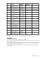
*Not shown
**Do not mix single- and dual-core processors or processors with different speeds or cache sizes.
‡REQUIREMENT:
For Customers in the EU only.
The use of the Original Spare part is regulated by RoHS legislation§.
If your unit contains a part that is labelled with the Modified Spare number, the Modified Spare must be ordered as
the replacement part in the EU.
Illustrated parts catalog
11
If your unit contains a part that is labelled with the Original Spare number, please order the Original Spare as the
replacement part in the EU. In this case either the Original Spare or the Modified Spare may be shipped which will
not affect performance or functionality of the unit.
§Directive 2002/95/EC restricts the use of lead, mercury, cadmium, hexavalent chromium, PBBs and PBDEs in
electronic products.
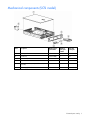
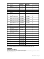
Mechanical components (SAS model)
Item
Description
Original spare
part number
Modified
spare part
number
Customer
self repair
1
Access panel
359244-001
—
Yes
2
Front bezel
392614-001
—
Yes
3
Hard drive blank
392613-001
—
Yes
4
Diskette drive slot cover (see "Plastics Kit,"
Item 25k)
—
—
5
Power supply blank
359246-001
—
Yes
Illustrated parts catalog
12
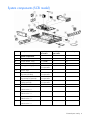
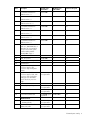
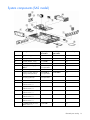
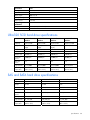
System components (SAS model)
Item
Description
Original spare
part number
Modified spare
part number
Customer self repair
System component
6
Hot-plug fan, 60 mm
289544-001
—
Yes
7
Front fan bracket, 6 bay
371148-001
—
Yes
8
Rear fan bracket, 2 bay
289558-001
—
Yes
9
Hot-plug power supply,
400 W
338022-001‡
See requirement
406393-001
Yes
10
PCI riser cages
—
—
—
a) PCI riser cage, with nonhot-plug PCI-X (standard)
359248-001‡
See requirement
411020-001
Yes
b) PCI riser cage, with PCIX hot-plug (optional)*
359260-001‡
See requirement
411022-001
Yes
Processor assemblies
—
—
—
a) 3.0-GHz Intel® Xeon™
1-MB L2 cache* **
378006-001
—
Yes
b) 3.2-GHz Intel® Xeon™
1-MB L2 cache* **
374233-001
—
Yes
c) 3.4-GHz Intel® Xeon™
1-MB L2 cache* **
364757-001
—
Yes
d) 3.6-GHz Intel® Xeon™
1-MB L2 cache* **
364758-001
—
Yes
e) 2.8-GHz Intel® Xeon™
2-MB L2 cache* **
399132-001
—
Yes
f) 3.0-GHz Intel® Xeon™ 2MB L2 cache* **
379427-001
—
Yes
11
Illustrated parts catalog
13
Item
Description
Original spare
part number
Modified spare
part number
Customer self repair
g) 3.0-GHz Intel® Xeon™
2-MB L2 cache LV* **
399764-001
—
Yes
h) 3.2-GHz Intel® Xeon™
2-MB L2 cache* **
379428-001
—
Yes
i) 3.4-GHz Intel® Xeon™ 2MB L2 cache* **
379429-001
—
Yes
j) 3.6-GHz Intel® Xeon™ 2MB L2 cache* **
379430-001
—
Yes
k) 3.8-GHz Intel® Xeon™
2-MB L2 cache* **
399133-001
—
Yes
l) 2.83-GHz Intel® Xeon™
dual-core, 1066-MHz FSB,
4-MB cache (for use with
dual-core processor SAS
system board assembly
number 012977-001
only)* **
403934-001
—
Yes
Boards
12
PPM, 12 V, 81 A
347884-001
—
Yes
13
System board
—
—
—
a) System board, with
processor cages and system
battery
392609-001
—
Yes
b) System board, dual-core
processor support, SAS,
with processor cages and
system battery (for use with
Intel® Xeon™ dual-core
processor only)*
409160-001‡
See requirement
411030-001
Yes
14
Power converter module
392611-001
—
Yes
15
SAS backplane, 8 bay
392610-001‡
See requirement
411024-001
Yes
16
Power button/LED board
366300-001‡
See requirement
411026-001
Yes
Media devices
17
Diskette drive, slimline,
1.44 MB (optional)
289550-001‡
See requirement
399311-001
Yes
18
CD-ROM drive, removable
slimline, IDE, 24X
228508-001‡
See requirement
399401-001
Yes
19
DVD-ROM drive, removable
slimline, 8X*
268795-001‡
See requirement
397928-001
Yes
SAS options cable kit*
392612-001
—
—
a) Drive cage cable
—
—
Yes
b) CD multi-bay cable
—
—
Yes
SAS option cable*
389952-001
—
Yes
Cables
20
21
Illustrated parts catalog
14
Item
Description
Original spare
part number
Modified spare
part number
Customer self repair
22
Signal cable kit*
228518-001
—
—
a) Power button/LED board
cable, 14 pin
—
—
Yes
b) PCI hot-plug LED board
cable
—
—
Yes
Miscellaneous cable kit*
366063-001
—
—
a) Diskette drive cable*
—
—
Yes
b) CD multibay adaptor
cable*
—
—
Yes
c) USB cable and
connector*
—
—
Yes
359254-001
—
Yes
Hardware kit*
228527-001
—
—
a) Screws, T-15, flat-head
—
—
Yes
b) Expansion slot cover
—
—
Yes
c) Screws, 6-32
—
—
Yes
Plastics kit*
359720-001
—
—
a) PCI slot release lever
—
—
Yes
b) PCI lightpipe, rear
—
—
Yes
c) PCI lightpipe, cover
—
—
Yes
d) PCI riser cage door latch
—
—
Yes
e) Thumbscrew with molded
cap, PCI slot 1
—
—
Yes
f) Standoff
—
—
Yes
g) Plastic standoff 0.134 in
—
—
Yes
h) Battery clip
—
—
Yes
i) PCI card guide retainer
—
—
Yes
j) Thumbscrew knob
—
—
Yes
k) Diskette drive slot cover
—
—
Yes
26
AC power cord*
187335-001
—
Yes
27
DVD/CD-ROM drive ejector
assembly*
371114-001
—
Yes
28
PCI expansion board
ejector*
359261-001
—
Yes
29
Battery, 3.3 V, lithium*
179322-001
—
Yes
30
Country kit*
359722-001
—
Yes
Rack mounting
hardware
23
2U Quick Deploy Rail
System*
Miscellaneous
24
25
Illustrated parts catalog
15
Item
Description
Original spare
part number
Modified spare
part number
Customer self repair
31
Return kit, pack box, and
cushions*
289545-001
—
Yes
32
T-15 Torx screwdriver*
199630-001
—
Yes
Memory
33
DIMM, 512 MB, registered
DDR2 SDRAM*
359241-001‡
See requirement
413384-001
Yes
34
DIMM, 1 GB, registered
DDR2 SDRAM*
359242-001‡
See requirement
413385-001
Yes
35
DIMM, 2 GB, registered
DDR2 SDRAM*
359243-001‡
See requirement
413386-001
Yes
36
DIMM, 2 GB, registered
DDR2 dual-rank SDRAM*
378021-001‡
See requirement
413387-001
Yes
37
DIMM, 4 GB, registered
DDR2 SDRAM*
379984-001‡
See requirement
413388-001
Yes
Options
38
Smart Array P600
Controller*
370855-001
—
Yes
39
SAS array cache board,
256-MB (with battery)*
309522-001
—
Yes
40
SAS array cache board,
512-MB (with battery)*
378202-001
—
Yes
41
42
SAS hot-plug hard drive
—
—
—
a) 36-GB, 10,000 rpm,
2.5 in*
376596-001
—
Yes
b) 72-GB, 10,000 rpm,
2.5 in*
376597-001
—
Yes
60-GB, 5,4000 rpm, SFF
SATA hard drive, 1 yr wty*
382264-001
—
Yes
*Not shown
**Do not mix single- and dual-core processors or processors with different speeds or cache sizes.
‡REQUIREMENT:
For Customers in the EU only.
The use of the Original Spare part is regulated by RoHS legislation§.
If your unit contains a part that is labelled with the Modified Spare number, the Modified Spare must be ordered as
the replacement part in the EU.
If your unit contains a part that is labelled with the Original Spare number, please order the Original Spare as the
replacement part in the EU. In this case either the Original Spare or the Modified Spare may be shipped which will
not affect performance or functionality of the unit.
§Directive 2002/95/EC restricts the use of lead, mercury, cadmium, hexavalent chromium, PBBs and PBDEs in
electronic products.
Illustrated parts catalog
16
Removal and replacement procedures
In this section
Introduction ........................................................................................................................................... 17
Required tools........................................................................................................................................ 17
Safety considerations.............................................................................................................................. 17
Preparation procedures........................................................................................................................... 18
Non-hot-plug procedures ......................................................................................................................... 22
Hot-plug procedures ............................................................................................................................... 44
Introduction
The SCSI model and SAS model servers look different. The procedures in this section apply to either
server model unless otherwise noted.
Required tools
You need the following items for some procedures:
•
T-15 Torx screwdriver (provided inside the server)
•
HP Insight Diagnostics software ("HP Insight Diagnostics" on page 70)
Safety considerations
Before performing service procedures, review all the safety information.
Preventing electrostatic discharge
To prevent damaging the system, be aware of the precautions you need to follow when setting up the
system or handling parts. A discharge of static electricity from a finger or other conductor may damage
system boards or other static-sensitive devices. This type of damage may reduce the life expectancy of the
device.
To prevent electrostatic damage:
•
Avoid hand contact by transporting and storing products in static-safe containers.
•
Keep electrostatic-sensitive parts in their containers until they arrive at static-free workstations.
•
Place parts on a grounded surface before removing them from their containers.
•
Avoid touching pins, leads, or circuitry.
•
Always be properly grounded when touching a static-sensitive component or assembly.
Server warnings and cautions
Before installing a server, be sure that you understand the following warnings and cautions.
Removal and replacement procedures
17
WARNING: To reduce the risk of electric shock or damage to the equipment:
• Do not disable the power cord grounding plug. The grounding plug is an important
safety feature.
• Plug the power cord into a grounded (earthed) electrical outlet that is easily
accessible at all times.
• Unplug the power cord from the power supply to disconnect power to the equipment.
• Do not route the power cord where it can be walked on or pinched by items placed
against it. Pay particular attention to the plug, electrical outlet, and the point where
the cord extends from the server.
WARNING: To reduce the risk of personal injury from hot surfaces, allow the drives and
the internal system components to cool before touching them.
CAUTION: Do not operate the server for long periods with the access panel open or removed. Operating
the server in this manner results in improper airflow and improper cooling that can lead to thermal damage.
Preparation procedures
To access some components and perform certain service procedures, you must perform one or more of the
following procedures:
•
Extend the server from the rack (on page 19).
If you are performing service procedures in an HP, Compaq branded, telco, or third-party rack
cabinet, you can use the locking feature of the rack rails to support the server and gain access to
internal components.
For more information about telco rack solutions, refer to the RackSolutions.com website
(http://www.racksolutions.com/hp).
•
Power down the server (on page 20).
If you must remove a server from a rack or a non-hot-plug component from a server, power down the
server.
•
Remove the server from the rack (on page 20).
If the rack environment, cabling configuration, or the server location in the rack creates awkward
conditions, remove the server from the rack.
Removal and replacement procedures
18
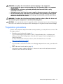
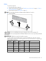
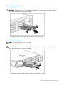
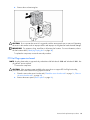
Extend the server from the rack
1.
Pull down the quick release levers on each side of the server to release the server from the rack.
2.
Extend the server on the rack rails until the server rail-release latches engage.
WARNING: To reduce the risk of personal injury or equipment damage, be sure that the
rack is adequately stabilized before extending a component from the rack.
WARNING: To reduce the risk of personal injury, be careful when pressing the server
rail-release latches and sliding the server into the rack. The sliding rails could pinch your
fingers.
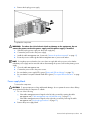
3.
After performing the installation or maintenance procedure, slide the server back into the rack:
a. Press the server rail-release latches and slide the server fully into rack.
b. Press the server firmly into the rack to secure it in place.
Removal and replacement procedures
19
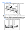
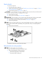
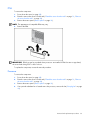
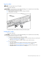
Power down the server
WARNING: To reduce the risk of personal injury, electric shock, or damage to the
equipment, remove the power cord to remove power from the server. The front panel
Power On/Standby button does not completely shut off system power. Portions of the
power supply and some internal circuitry remain active until AC power is removed.
IMPORTANT: If installing a hot-plug device, it is not necessary to power down the server.
1.
Back up the server data.
2.
Shut down the operating system as directed by the operating system documentation.
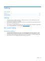
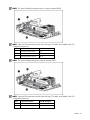
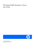
3.
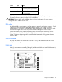
If the server is installed in a rack, press the UID LED button on the front panel (1). Blue LEDs
illuminate on the front and rear panels of the server.
4.
Press the Power On/Standby button to place the server in standby mode (2). When the server
activates standby power mode, the system power LED changes to amber.
5.
If the server is installed in a rack, locate the server by identifying the illuminated rear UID LED button.
6.
Disconnect the power cords.
The system is now without power.
Remove the server from the rack
To remove the server from an HP, Compaq branded, telco, or third-party rack:
1.
Power down the server (on page 20).
2.
Extend the server from the rack (on page 19).
3.
Disconnect the cabling and remove the server from the rack. For more information, refer to the
documentation that ships with the rack mounting option.
4.
Place the server on a sturdy, level surface.
Removal and replacement procedures
20
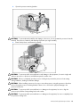
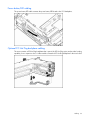
Access the product rear panel
Cable management arm with left-hand swing
To access the server rear panel, open the cable management arm.
To close the cable management arm, reverse this procedure.
Cable management arm with right-hand swing
NOTE: To access some components, you may need to remove the cable management arm.
To access the product rear panel components, open the cable management arm.
1.
Power down the server (on page 20).
2.
Swing open the cable management arm.
3.
Remove the cables from the cable trough.
4.
Remove the cable management arm.
Removal and replacement procedures
21
To close the cable management arm, reverse this procedure.
Non-hot-plug procedures
Access panel
WARNING: To reduce the risk of personal injury from hot surfaces, allow the drives and
the internal system components to cool before touching them.
CAUTION: Do not operate the server for long periods with the access panel open or removed. Operating
the server in this manner results in improper airflow and improper cooling that can lead to thermal damage.
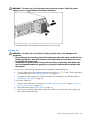
To remove the component:
1.
Power down the server if performing a non-hot-plug installation or maintenance procedure ("Power
down the server" on page 20).
2.
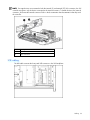
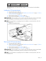
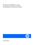
Extend the server from the rack, if applicable ("Extend the server from the rack" on page 19).
3.
Lift up on the hood latch handle and remove the access panel.
To replace the component, reverse the removal procedure.
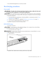
DVD/CD-ROM drive
To remove the component:
CAUTION: To prevent improper cooling and thermal damage, do not operate the server unless all bays
are populated with either a component or a blank.
1.
Power down the server (on page 20).
IMPORTANT: The ejector button is recessed to prevent accidental ejection; it may be helpful to use a pen
or similar shaped object to access the button.
2.
Remove the drive.
To replace the drive, slide the drive into the bay until the drive is fully seated.
Removal and replacement procedures
22
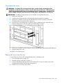
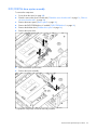
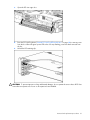
DVD/CD-ROM drive ejector assembly
To remove the component:
1.
Power down the server (on page 20).
2.
Extend or remove the server from the rack ("Extend the server from the rack" on page 19, "Remove
the server from the rack" on page 20).
3.
Remove the access panel ("Access panel" on page 22).
4.
Remove the DVD/CD-ROM drive, if installed ("DVD/CD-ROM drive" on page 22).
5.
Remove the diskette drive ("Diskette drive option" on page 24).
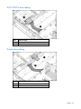
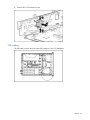
6.
Remove the ejector lever.
7.
Press and hold the ejector button.
8.
Remove the ejector assembly.
To replace the component, reverse the removal procedure.
Removal and replacement procedures
23
Diskette drive option
To remove the component:
CAUTION: To prevent improper cooling and thermal damage, do not operate the server unless all bays
are populated with either a component or a blank.
1.
Power down the server (on page 20).
2.
Extend or remove the server from the rack ("Extend the server from the rack" on page 19, "Remove
the server from the rack" on page 20).
3.
Remove the access panel ("Access panel" on page 22).
4.
Remove the diskette drive.
To replace the component, reverse the removal procedure.
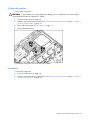
Front bezel
To remove the component:
1.
Power down the server (on page 20).
2.
Extend or remove the server from the rack ("Extend the server from the rack" on page 19, "Remove
the server from the rack" on page 20).
Removal and replacement procedures
24
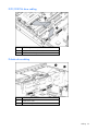
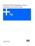
3.
Remove the two screws and detach the front bezel.
To replace the component, reverse the removal procedure.
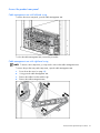
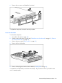
Front fan bracket
To remove the component:
1.
Power down the server (on page 20).
2.
Extend or remove the server from the rack ("Extend the server from the rack" on page 19, "Remove
the server from the rack" on page 20).
3.
Remove the access panel ("Access panel" on page 22).
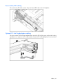
4.
Remove the front fan bracket.
5.
Remove all hot-plug fans from the front fan bracket ("Hot-plug fan" on page 49).
To replace the front fan bracket, reverse the removal steps and press down on the top of each fan to be
sure it is seated properly.
Removal and replacement procedures
25
Rear fan bracket
To remove the component:
1.
Power down the server (on page 20).
2.
Extend or remove the server from the rack ("Extend the server from the rack" on page 19, "Remove
the server from the rack" on page 20).
3.
Remove the access panel ("Access panel" on page 22).
CAUTION: To prevent damage to the server or expansion boards, power down the server and remove all
AC power cords before removing or installing the PCI riser cage.
4.
Remove the PCI riser cage.
5.
Remove the front fan bracket ("Front fan bracket" on page 25).
IMPORTANT: For this procedure, you do not need to remove the hot-plug fans from the front fan bracket.
When reinstalling the front fan bracket, press the top of each fan to be sure it seats securely.
6.
Remove the hot-plug fans from the rear fan bracket ("Hot-plug fan" on page 49).
7.
Remove the system board.
NOTE: When removing the system board, you may leave the DIMMs, the processors, the PPMs, the Smart
Array 6i memory module, and the system battery on the system board, unless you are replacing them as
failed items.
8.
Remove the rear fan bracket.
To replace the component, reverse the removal procedure.
Battery-backed write cache procedures
NOTE: This feature applies only to SCSI models.
Two types of procedures are provided for the BBWC option:
•
Removal and replacement of failed components:
•
Removing the Smart Array 6i cache module
•
Removing the BBWC battery pack
Removal and replacement procedures
26
•
Recovery of cached data from a failed server ("Recovering data from the battery-backed write
cache" on page 29)
CAUTION: Do not detach the cable that connects the battery pack to the cache module. Detaching the
cable causes any unsaved data in the cache module to be lost.
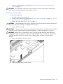
Smart Array 6i cache module
To remove the component:
1.
Power down the server (on page 20).
2.
Extend or remove the server from the rack ("Extend the server from the rack" on page 19, "Remove
the server from the rack" on page 20).
3.
Remove the access panel ("Access panel" on page 22).
CAUTION: To prevent damage to the server or expansion boards, power down the server and remove all
AC power cords before removing or installing the PCI riser cage.
4.
Remove the PCI riser cage.
CAUTION: To prevent a server malfunction or damage to the equipment, do not add or remove the battery
pack while an array capacity expansion, RAID level migration, or stripe size migration is in progress.
CAUTION: After the server is powered down, wait 15 seconds and then check the amber LED before
unplugging the cable from the cache module. If the amber LED blinks after 15 seconds, do not remove the
cable from the cache module. The cache module is backing up data, and data is lost if the cable is
detached.
5.
Remove the cable from the plastic retainer.
6.
Remove the Smart Array 6i cache module.
Removal and replacement procedures
27
7.
Disconnect the cable.
To replace the component, reverse the removal procedure.
CAUTION: To prevent damage to the cache module during installation, be sure the cache module is fully
inserted before pressing down.
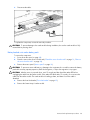
Battery-backed write cache battery pack
To remove the component:
1.
Power down the server (on page 20).
2.
Extend or remove the server from the rack ("Extend the server from the rack" on page 19, "Remove
the server from the rack" on page 20).
3.
Remove the access panel ("Access panel" on page 22).
CAUTION: To prevent a server malfunction or damage to the equipment, do not add or remove the battery
pack while an array capacity expansion, RAID level migration, or stripe size migration is in progress.
CAUTION: After the server is powered down, wait 15 seconds and then check the amber LED before
unplugging the cable from the cache module. If the amber LED blinks after 15 seconds, do not remove the
cable from the cache module. The cache module is backing up data, and data is lost if the cable is
detached.
4.
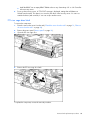
Remove the front fan bracket ("Front fan bracket" on page 25).
5.
Remove the Smart Array 6i cache module.
Removal and replacement procedures
28
6.
Remove the BBWC enabler, also known as the battery pack.
To replace the component, reverse the removal procedure.
IMPORTANT: The battery pack might have a low charge when installed. In this case, a POST error
message is displayed when the server is powered up, indicating that the battery pack is temporarily
disabled. No action is necessary on your part. The internal circuitry automatically recharges the batteries
and enables the battery pack. This process might take up to four hours. During this time, the cache module
functions properly, but without the performance advantage of the battery pack.
NOTE: The data protection and the time limit also apply if a power outage occurs. When power is restored
to the system, an initialization process writes the preserved data to the hard drives.
Recovering data from the battery-backed write cache
If the server fails, you can recover any data temporarily trapped in the BBWC by using the following
procedure.
CAUTION: Before starting this procedure, read the information about protecting against electrostatic
discharge ("Preventing electrostatic discharge" on page 17).
1.
2.
Perform one of the following:
•
Set up a recovery server station using an identical server model. Do not install any internal drives
or BBWC in this server. (This is the preferred option.)
•
Find a server that has enough empty drive bays to accommodate all the drives from the failed
server and that meets all the other requirements for drive and array migration.
Power down the failed server ("Power down the server" on page 20). If any data is trapped in the
cache module, an amber LED on the module blinks every 15 seconds.
CAUTION: Do not detach the cable that connects the battery pack to the cache module. Detaching the
cable causes any unsaved data in the cache module to be lost.
3.
Transfer the hard drives from the failed server to the recovery server station.
4.
Remove the BBWC [cache module and battery pack] from the failed server.
5.
Perform one of the following:
•
Install the BBWC into an empty BBWC DIMM socket on the system board of the recovery server.
Removal and replacement procedures
29
•
6.
Install the BBWC into an empty BBWC DIMM socket on any Smart Array 641 or 642 Controller
in the recovery server.
Power up the recovery server. A 1759 POST message is displayed, stating that valid data was
flushed from the cache. This data is now stored on the drives in the recovery server. You can now
transfer the drives (and controller, if one was used) to another server.
PCI riser cage door latch
To remove the component:
1.
Extend or remove the server from the rack ("Extend the server from the rack" on page 19, "Remove
the server from the rack" on page 20).
2.
Remove the access panel ("Access panel" on page 22).
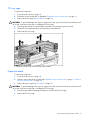
3.
Open the PCI riser cage door.
4.
Remove the PCI riser cage door latch.
To replace the component, reverse the removal procedure.
Removal and replacement procedures
30
PCI riser cage
To remove the component:
1.
Power down the server (on page 20).
2.
Extend the server from the rack, if applicable ("Extend the server from the rack" on page 19).
3.
Remove the access panel ("Access panel" on page 22).
CAUTION: To prevent damage to the server or expansion boards, power down the server and remove all
AC power cords before removing or installing the PCI riser cage.
4.
Disconnect any internal or external cables connected to any existing expansion boards.
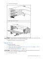
5.
Lift the PCI riser cage thumbscrews and turn them counter-clockwise.
6.
Remove the PCI riser cage.
To replace the component, reverse the removal procedure.
Expansion board
To remove the component:
1.
Power down the server (on page 20).
2.
Extend or remove the server from the rack ("Extend the server from the rack" on page 19, "Remove
the server from the rack" on page 20).
3.
Remove the access panel ("Access panel" on page 22).
CAUTION: To prevent damage to the server or expansion boards, power down the server and remove all
AC power cords before removing or installing the PCI riser cage.
4.
Disconnect any cables connecting the expansion board to the PCI riser cage.
5.
Remove the PCI riser cage.
Removal and replacement procedures
31
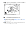
6.
Unlock the PCI retaining clip.
7.
Remove the expansion board.
CAUTION: To prevent improper cooling and thermal damage, do not operate the server unless all PCI slots
have either an expansion slot cover or an expansion board installed.
To replace the component, reverse the removal procedure.
Expansion slot cover
To remove the component:
1.
Power down the server (on page 20).
2.
Extend or remove the server from the rack ("Extend the server from the rack" on page 19, "Remove
the server from the rack" on page 20).
3.
Remove the access panel ("Access panel" on page 22).
CAUTION: To prevent damage to the server or expansion boards, power down the server and remove all
AC power cords before removing or installing the PCI riser cage.
4.
Remove the PCI riser cage.
Removal and replacement procedures
32
CAUTION: To prevent improper cooling and thermal damage, do not operate the server unless all PCI slots
have either an expansion slot cover or an expansion board installed.
5.
Remove the expansion slot cover.
To replace the component, reverse the removal procedure.
Expansion board ejector/divider
NOTE: This component is available only with the optional, hot-plug PCI riser cage.
To remove the component:
1.
Power down the server (on page 20).
2.
Extend or remove the server from the rack ("Extend the server from the rack" on page 19, "Remove
the server from the rack" on page 20).
3.
Remove the access panel ("Access panel" on page 22).
4.
Remove the PCI riser cage.
CAUTION: To prevent damage to the server or expansion boards, power down the server and remove all
AC power cords before removing or installing the PCI riser cage.
Removal and replacement procedures
33
5.
Remove the expansion board ejector/divider.
CAUTION: To prevent improper cooling and thermal damage, do not operate the server unless all PCI slots
have either an expansion slot cover or an expansion board installed.
To replace the component, reverse the removal procedure.
PCI slot release lever
To remove the component:
1.
Power down the server (on page 20).
2.
Extend or remove the server from the rack ("Extend the server from the rack" on page 19, "Remove
the server from the rack" on page 20).
3.
Remove the access panel ("Access panel" on page 22).
CAUTION: To prevent damage to the server or expansion boards, power down the server and remove all
AC power cords before removing or installing the PCI riser cage.
4.
Remove the PCI riser cage.
CAUTION: To prevent improper cooling and thermal damage, do not operate the server unless all
expansion slots have either an expansion slot cover or an expansion board installed.
5.
Remove the expansion board from the slot, if installed.
6.
Remove the expansion slot cover from the slot, if installed.
Removal and replacement procedures
34
7.
Remove the PCI slot release lever.
To replace the component, reverse the removal procedure.
PCI lightpipe and cover
NOTE: This component is available only with the optional, hot-plug PCI riser cage.
To remove the component:
1.
Power down the server (on page 20).
2.
Extend or remove the server from the rack ("Extend the server from the rack" on page 19, "Remove
the server from the rack" on page 20).
3.
Remove the access panel ("Access panel" on page 22).
4.
Remove the PCI lightpipe cover.
Removal and replacement procedures
35
5.
Slide the lightpipe out of the chassis.
To replace the component, reverse the removal procedure.
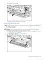
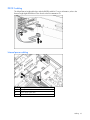
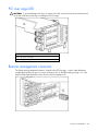
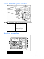
Power converter module
To remove the component:
1.
Power down the server (on page 20).
2.
Extend or remove the server from the rack ("Extend the server from the rack" on page 19, "Remove
the server from the rack" on page 20).
3.
Remove the access panel ("Access panel" on page 22).
4.
Remove the front fan bracket ("Front fan bracket" on page 25).
IMPORTANT: For this procedure, you do not need to remove the hot-plug fans from the front fan bracket.
When reinstalling the front fan bracket, press the top of each fan to be sure it seats securely.
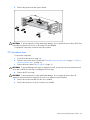
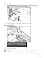
5.
Remove all hot-plug power supplies ("Hot-plug power supply" on page 47).
6.
Disconnect all power cables.
7.
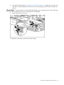
Remove the power converter module.
Removal and replacement procedures
36
NOTE: Cables are removed for clarity.
To replace the component, reverse the removal procedure.
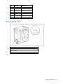
Power button/LED board
To remove the component:
1.
Power down the server (on page 20).
2.
Extend or remove the server from the rack ("Extend the server from the rack" on page 19, "Remove
the server from the rack" on page 20).
3.
Remove the front bezel.
4.
Remove the access panel ("Access panel" on page 22).
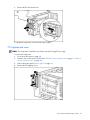
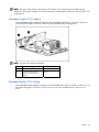
5.
Remove the BBWC battery pack.
NOTE: This feature applies only to SCSI models.
6.
Remove the power button/LED board.
To replace the component, reverse the removal procedure.
Removal and replacement procedures
37
DIMMs
To remove the component:
1.
Power down the server (on page 20).
2.
Extend or remove the server from the rack ("Extend the server from the rack" on page 19, "Remove
the server from the rack" on page 20).
3.
Remove the access panel ("Access panel" on page 22).
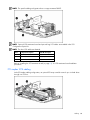
NOTE: The server ships with at least two DIMMs installed in DIMM slots 1A and 2A.
4.
Remove the DIMM.
CAUTION: Be sure to install DIMMs in the proper configuration. Refer to the Documentation CD.
CAUTION: Use only Compaq branded or HP DIMMs. DIMMs from other sources may adversely affect data
integrity.
IMPORTANT: DIMMs do not seat fully if turned the wrong way.
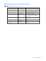
To replace a DIMM, align the DIMM with the slot and insert the DIMM firmly. When fully seated, the
DIMM slot latches lock into place. The following table lists all seven valid combinations of single-rank and
dual-rank DIMM configurations.
Configuration
Bank A
Bank B
1
Single
2
Single
Single
3
Single
Single
4
Dual
5
Dual
Single
6
Dual
Single
7
Dual
Dual
Bank C
Notes
Single
Online Spare not supported
Online Spare not supported
Single
Online Spare not supported
Online Spare not supported
Removal and replacement procedures
38
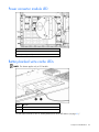
PPM
To remove the component:
1.
Power down the server (on page 20).
2.
Extend or remove the server from the rack ("Extend the server from the rack" on page 19, "Remove
the server from the rack" on page 20).
3.
Remove the access panel ("Access panel" on page 22).
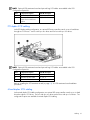
NOTE: The appearance of compatible PPMs may vary.
4.
Remove the PPM.
IMPORTANT: PPM slots must be populated when processors are installed. If PPM slots are not populated,
the server halts during POST or does not boot.
To replace the component, reverse the removal procedure.
Processor
To remove the component:
1.
Power down the server (on page 20).
2.
Extend or remove the server from the rack ("Extend the server from the rack" on page 19, "Remove
the server from the rack" on page 20).
3.
Remove the access panel ("Access panel" on page 22).
4.
If an optional redundant fan is located next to the processor, remove the fan ("Hot-plug fan" on page
49).
Removal and replacement procedures
39
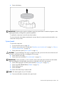
5.
Open the processor retaining bracket.
CAUTION: To prevent thermal instability and damage to the server, do not separate the processor from the
heatsink. The processor, heatsink, and retaining clip make up a single assembly.
6.
Remove the processor and heatsink assembly.
CAUTION: To prevent possible server malfunction and damage to the equipment, do not mix single- and
dual-core processors or processors with different speeds or cache sizes.
CAUTION: Failure to completely open the processor locking lever prevents the processor from seating
during installation, leading to hardware damage.
CAUTION: When installing a processor, be sure to secure the processor using the processor socket lever
before closing the processor retaining bracket. Failure to do so will result in physical damage to the
processor and server.
CAUTION: To prevent possible server malfunction or damage to the equipment, be sure to align the
processor pins with the corresponding holes in the socket.
CAUTION: To prevent possible server malfunction or damage to the equipment, be sure to completely close
the processor locking lever.
Removal and replacement procedures
40
IMPORTANT: If upgrading processor speed, update the system ROM before installing the processor.
IMPORTANT: Processor socket 1 and PPM slot 1 must be populated at all times or the server does not
function properly.
IMPORTANT: PPM slots must be populated when processors are installed. If PPM slots are not populated,
the server halts during POST or does not boot.
IMPORTANT: If you replace a failed processor or processors, clear the status log in RBSU after powering
up the server. For RBSU procedures, refer to the Documentation CD.
To replace the component, reverse the removal procedure.
Battery
If the server no longer automatically displays the correct date and time, you may need to replace the
battery that provides power to the real-time clock.
WARNING: The computer contains an internal lithium manganese dioxide, a vanadium
pentoxide, or an alkaline battery pack. A risk of fire and burns exists if the battery pack
is not properly handled. To reduce the risk of personal injury:
• Do not attempt to recharge the battery.
• Do not expose the battery to temperatures higher than 60°C (140°F).
• Do not disassemble, crush, puncture, short external contacts, or dispose of in fire or
water.
• Replace only with the spare designated for this product.
To remove the component:
1.
Power down the server (on page 20).
2.
Extend or remove the server from the rack ("Extend the server from the rack" on page 19, "Remove
the server from the rack" on page 20).
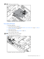
3.
Remove the access panel ("Access panel" on page 22).
4.
Remove the PCI riser cage.
CAUTION: To prevent damage to the server or expansion boards, power down the server and remove all
AC power cords before removing or installing the PCI riser cage.
Removal and replacement procedures
41
5.
Remove the battery.
IMPORTANT: Replacing the system board battery resets the system ROM to its default configuration. After
replacing the battery, reconfigure the system through RBSU.
To replace the component, reverse the removal procedure.
For more information about battery replacement or proper disposal, contact an authorized reseller or an
authorized service provider.
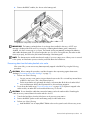
System board
To remove the component:
1.
Power down the server (on page 20).
2.
Extend or remove the server from the rack ("Extend the server from the rack" on page 19, "Remove
the server from the rack" on page 20).
3.
Remove the access panel ("Access panel" on page 22).
CAUTION: To prevent damage to the server or expansion boards, power down the server and remove all
AC power cords before removing or installing the PCI riser cage.
4.
Remove the PCI riser cage.
5.
Remove the front fan bracket ("Front fan bracket" on page 25).
IMPORTANT: For this procedure, you do not need to remove the hot-plug fans from the front fan bracket.
When reinstalling the front fan bracket, press the top of each fan to be sure it seats securely.
6.
Remove the hot-plug fans from the rear fan bracket ("Hot-plug fan" on page 49).
7.
Remove any DDR SDRAM DIMMs ("DIMMs" on page 38).
8.
Remove the processors.
9.
Remove the PPMs.
10. Remove the Smart Array 6i cache module.
NOTE: This feature applies only to SCSI models.
11. Disconnect all cables connected to the system board.
Removal and replacement procedures
42
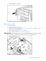
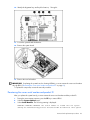
12. Identify the alignment keys and keyhole locations, 1 through 4.
13. Loosen the system board thumbscrew.
14. Remove the system board.
15. Remove the rear fan bracket.
IMPORTANT: If replacing the system board or clearing NVRAM, you must re-enter the server serial number
through RBSU ("Re-entering the server serial number and product ID" on page 43).
To replace the component, reverse the removal procedure.
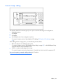
Re-entering the server serial number and product ID
After you replace the system board, you must re-enter the server serial number and the product ID.
1.
During the server startup sequence, press the F9 key to access RBSU.
2.
Select the System Options menu.
3.
Select Serial Number. The following warning is displayed:
WARNING! WARNING! WARNING! The serial number is loaded into the system
during the manufacturing process and should NOT be modified. This option
Removal and replacement procedures
43
should only be used by qualified service personnel. This value should
always match the serial number sticker located on the chassis.
4.
Press the Enter key to clear the warning.
5.
Enter the serial number and press the Enter key.
6.
Select Product ID.
7.
Enter the product ID and press the Enter key.
8.
Press the Esc key to close the menu.
9.
Press the Esc key to exit RBSU.
10. Press the F10 key to confirm exiting RBSU. The server will automatically reboot.
Hot-plug procedures
Hot-plug SCSI hard drive
To remove the component:
CAUTION: To prevent improper cooling and thermal damage, do not operate the server unless all bays
are populated with either a component or a blank.
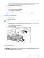
1.
Determine the status of the hard drive from the hot-plug hard drive LEDs ("Hot-plug SCSI hard drive
LEDs" on page 85).
2.
Back up all server data on the hard drive.
3.
Remove the hard drive.
To replace the component, reverse the removal procedure.
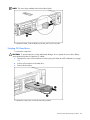
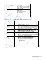
SCSI hard drive blank
To remove the component:
CAUTION: To prevent improper cooling and thermal damage, do not operate the server unless all bays
are populated with either a component or a blank.
Removal and replacement procedures
44
NOTE: The server ships standard with five hard drive blanks.
To replace the blank, slide the blank into the bay until it locks into place.
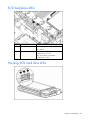
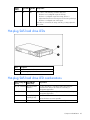
Hot-plug SAS hard drive
To remove the component:
CAUTION: To prevent improper cooling and thermal damage, do not operate the server unless all bays
are populated with either a component or a blank.
1.
Determine the status of the hard drive from the hot-plug SAS hard drive LED combinations (on page
87).
2.
Back up all server data on the hard drive.
3.
Remove the hard drive.
To replace the component, reverse the removal procedure.
Removal and replacement procedures
45
SAS hard drive blank
To remove the component:
CAUTION: To prevent improper cooling and thermal damage, do not operate the server unless all bays
are populated with either a component or a blank.
To replace the blank, slide the blank into the bay until it locks into place.
Universal hot-plug tape drive
NOTE: This feature applies only to SCSI models.
To remove the component:
CAUTION: To prevent improper cooling and thermal damage, do not operate the server unless all bays
are populated with either a component or a blank.
To replace the component, slide the drive into the bay until it locks into place.
Removal and replacement procedures
46
Tape drive blank
NOTE: This feature applies only to SCSI models.
To remove the component:
CAUTION: To prevent improper cooling and thermal damage, do not operate the server unless all bays
are populated with either a component or a blank.
1.
Reach underneath and squeeze the middle of the tape drive blank.
2.
Pull the blank out of the bay.
To replace the blank, slide the blank into the bay until it locks into place.
Hot-plug power supply
To remove the component:
CAUTION: To prevent improper cooling and thermal damage, do not operate the server unless all bays
are populated with either a component or a blank.
1.
2.
Determine how many hot-plug power supplies are installed:
•
If only one hot-plug power supply is installed, power down and remove the power cord from the
server ("Power down the server" on page 20).
•
If more than one hot-plug power supply is installed, continue with the next step.
Do one of the following:
•
If the cable management arm is hinged on the left side, proceed by opening the cable
management arm ("Cable management arm with left-hand swing" on page 21).
•
If the cable management arm is hinged on the right side, proceed by removing the cable
management arm ("Non-hot-plug procedures" on page 22).
Removal and replacement procedures
47
3.
Remove the hot-plug power supply.
To replace the component:
WARNING: To reduce the risk of electric shock or damage to the equipment, do not
connect the power cord to the power supply until the power supply is installed.
1.
Slide the hot-plug power supply into the power supply bay.
2.
Connect the power cord to the power supply.
3.
Install the cable management arm, if removed. ("Access the product rear panel" on page 21)
4.
Route the power cord through the cable management arm or power cord anchor.
NOTE: If using the power cord anchor, be sure to leave enough slack in the power cord so that the
redundant power supply can be removed without disconnecting the power cord from the primary power
supply.
5.
Close the cable management arm.
6.
Connect the power cord to the power source.
7.
Be sure that the power supply LED is green ("Rear panel LEDs and buttons" on page 78).
8.
Be sure that the front panel external health LED is green ("Front panel LEDs and buttons" on page
76).
Power supply blank
To remove the component:
CAUTION: To prevent improper cooling and thermal damage, do not operate the server unless all bays
are populated with either a component or a blank.
1.
2.
Do one of the following:
•
If the cable management arm is hinged on the left side, proceed by opening the cable
management arm ("Cable management arm with left-hand swing" on page 21).
•
If the cable management arm is hinged on the right side, proceed by removing the cable
management arm ("Non-hot-plug procedures" on page 22).
Remove the power supply blank.
Removal and replacement procedures
48
WARNING: To reduce the risk of personal injury from hot surfaces, allow the power
supply or power supply blank to cool before touching it.
To replace the blank, slide the blank into the bay until it locks into place.
Hot-plug fan
WARNING: To reduce the risk of electric shock, personal injury, and damage to the
equipment:
• Do not attempt to service any parts of the equipment other than those specified in the
following procedure. Any other activities may require that you shut down the server
and remove the power cord.
• Installation and maintenance of this product must be performed by individuals who
are knowledgeable about the procedures, precautions and hazards associated with
the product.
You must observe the following requirements when installing redundant hot-plug fans:
•
To ensure optimum cooling, populate the primary fan locations, 2, 4, 5, 6, and 7, before populating
the redundant locations ("Identifying hot-plug fans" on page 90).
•
If a primary fan fails, replace the non-functioning fan before installing fans in redundant locations
("Identifying hot-plug fans" on page 90).
To remove the component:
1.
Extend or remove the server from the rack ("Extend the server from the rack" on page 19, "Remove
the server from the rack" on page 20).
2.
Remove the access panel ("Access panel" on page 22).
3.
If the server is operating with less than seven functional fans, power down the server (on page 20),
then continue with the next step.
Removal and replacement procedures
49
4.
Remove the non-functioning fan.
CAUTION: Do not operate the server for long periods with the access panel open or removed. Operating
the server in this manner results in improper airflow and improper cooling that can lead to thermal damage.
IMPORTANT: For optimum cooling, install fans in all primary fan locations. For more information, refer to
the fan locations table ("Identifying hot-plug fans" on page 90).
To replace the component, reverse the removal procedure.
PCI Hot Plug expansion board
NOTE: Hot-plug functionality is supported only under Microsoft® Windows® 2000 and Windows® 2003. Hotplug drivers are not required.
To remove the component:
CAUTION: If the operating system installed on the server does not support PCI Hot Plug functionality,
power down the server before removing expansion boards.
1.
Extend or remove the server from the rack ("Extend the server from the rack" on page 19, "Remove
the server from the rack" on page 20).
2.
Remove the access panel ("Access panel" on page 22).
Removal and replacement procedures
50
3.
Open the PCI riser cage door.
4.
Press the PCI Hot Plug button ("Internal PCI Hot Plug LEDs and button" on page 90) to remove power
from the slot. When the green power LED on the slot stops flashing, power has been removed from
the slot.
5.
Unlock the PCI retaining clip.
CAUTION: To prevent improper cooling and thermal damage, do not operate the server unless all PCI slots
have either an expansion slot cover or an expansion board installed.
Removal and replacement procedures
51
6.
Remove the expansion board.
To replace the component, reverse the removal procedure.
PCI Hot Plug expansion slot cover
NOTE: Hot-plug functionality is supported only under Microsoft® Windows® 2000 and Windows® 2003. Hotplug drivers are not required.
To remove the component:
CAUTION: If the operating system installed on the server does not support PCI Hot Plug functionality,
power down the server (on page 20) before removing expansion boards.
1.
Extend or remove the server from the rack ("Extend the server from the rack" on page 19, "Remove
the server from the rack" on page 20).
2.
Remove the access panel ("Access panel" on page 22).
3.
Open the PCI riser cage door.
Removal and replacement procedures
52
4.
Press the PCI Hot Plug button ("Internal PCI Hot Plug LEDs and button" on page 90) to remove power
from the slot. When the green power LED on the slot stops flashing, power has been removed from
the slot.
CAUTION: To prevent improper cooling and thermal damage, do not operate the server unless all PCI slots
have either an expansion slot cover or an expansion board installed.
5.
Remove the expansion slot cover.
To replace the component, reverse the removal procedure.
Removal and replacement procedures
53
Cabling
In this section
Cabling................................................................................................................................................. 54
SAS model cabling................................................................................................................................. 54
SCSI model cabling ................................................................................................................................ 58
Cabling
This section provides guidelines that help you make informed decisions about cabling the server and
hardware options to optimize performance.
For information on cabling the optional RILOE II board, refer to the HP Remote Insight Lights-Out Edition II
User Guide on the Documentation CD.
For information on cabling peripheral components, refer to the white paper on high-density deployment in
HP or Compaq branded racks on the HP website (http://www.hp.com).
SAS model cabling
SAS hard drive cabling
The HP ProLiant DL380 Generation 4 Server Service and Maintenance Guide SAS model uses a serial
attached SCSI bus to connect SAS hard drives on a SAS backplane to a PCI SAS controller. In a SAS
environment, each hard drive has a direct connection to the SAS controller. Two cables connect the PCI
SAS controller to the SAS backplane. Each cable controls four SAS drives.
Cabling
54
NOTE: If storage devices are connected to both the internal (1I) and external (1E) SAS connectors, the SAS
controller recognizes only the devices connected to the internal connector. To attach devices to the external
connector, disconnect the internal connector. Refer to the documentation that documentation that ships with
the controller.
Item
Description
1
SAS connector 1
2
SAS connector 2
USB cabling
The USB cable connects the front panel USB connector to the SAS backplane.
Cabling
55
DVD/CD-ROM drive cabling
Item
Cable description
1
DVD/CD-ROM drive cable
2
DVD/CD-ROM drive system cable
Diskette drive cabling
Item
Cable description
1
Diskette drive cable
2
Diskette drive system cable
Cabling
56
Power button/LED cabling
The power button/LED cable connects the power button/LED board to the SAS backplane.
Optional PCI Hot Plug backplane cabling
The server contains a PCI Hot Plug backplane that is part of the PCI Hot Plug option and provides hot-plug
capability for two expansion slots. A ribbon cable connects the PCI Hot Plug backplane to the riser board.
Cabling
57
RILOE II cabling
The 30-pin Remote Insight cable ships with the RILOE II cable kit. For more information, refer to the
Remote Insight Lights-Out Edition II User Guide on the Documentation CD.
Internal power cabling
Item
Description
1
System power cable
2
Power supply signal cable
3
SAS power cable
SCSI model cabling
IMPORTANT: If a simplex or duplex cabling configuration is not cabled correctly, the SCSI configuration
error LED will illuminate. Refer to "SCSI Backplane LEDs (on page 85)" to locate the LED.
Cabling
58
NOTE: The server ships with two identical short SCSI cables. Two optional long SCSI cables may be
obtained for PCI Array Controllers. One optional terminator board may be obtained to support duplex SCSI
configurations.
Embedded simplex SCSI cabling
In the embedded simplex cabling configuration, the embedded Smart Array 6i Controller controls up to
six hard drives through one SCSI bus. The server ships standard with this configuration.
NOTE: The short SCSI cables are identical.
Item
Component description
SCSI IDs managed
1
Short SCSI cable
0, 1, 2, 3, 4, 5
2
Short SCSI cable used to
jumper the two SCSI buses
together
N/A
Embedded duplex SCSI cabling
In the embedded duplex cabling configuration, the embedded Smart Array 6i Controller controls up to six
hard drives through two SCSI buses: one bus with up to two drives and the other bus with up to four
drives.
Cabling
59
NOTE: This specific cabling configuration does not support external VHDCI.
NOTE: Optional SCSI terminator board and optional long SCSI cables are available in the SCSI
Configuration Option Kit.
NOTE: The short SCSI cables are identical.
Item
Component description
SCSI IDs managed
1
Short SCSI cable
0, 1
2
Short SCSI cable
2, 3, 4, 5
3
Optional terminator board
N/A
Refer to "Installing the SCSI terminator board (on page 63)" for SCSI terminator board installation
procedures.
PCI simplex SCSI cabling
In the PCI simplex cabling configuration, an optional PCI array controller controls up to six hard drives
through one SCSI bus.
Cabling
60
NOTE: Optional SCSI terminator board and optional long SCSI cables are available in the SCSI
Configuration Option Kit.
Item
Component description
SCSI IDs managed
1
Optional long SCSI cable
0, 1, 2, 3, 4, 5
2
Short SCSI cable used to
jumper the two SCSI buses
together
N/A
PCI duplex SCSI cabling
In the PCI duplex cabling configuration, an optional PCI array controller controls up to six hard drives
through two SCSI buses: one bus with up to two drives and one bus with up to four drives.
NOTE: Optional SCSI terminator board and optional long SCSI cables are available in the SCSI
Configuration Option Kit.
Item
Component description
SCSI IDs managed
1
Optional long SCSI cable
0, 1
2
Optional long SCSI cable
2, 3, 4, 5
3
Optional terminator board
N/A
Refer to "Installing the SCSI terminator board (on page 63)" for SCSI terminator board installation
procedures.
Mixed duplex SCSI cabling
In the mixed duplex SCSI cabling configuration, an optional PCI array controller controls up to six hard
drives through two SCSI buses: one bus with up to two drives and one bus with up to four drives. Two
configuration options are available for mixed duplex SCSI cabling.
Cabling
61
NOTE: This specific cabling configuration does not support external VHDCI.
NOTE: Optional SCSI terminator board and optional long SCSI cables are available in the SCSI
Configuration Option Kit.
Item
Component description
SCSI IDs managed
1
Optional long SCSI cable
0, 1
2
Short SCSI cable
2, 3, 4, 5
3
Optional terminator board
N/A
NOTE: This specific cabling configuration supports external VHDCI.
NOTE: Optional SCSI terminator board and optional long SCSI cables are available in the SCSI
Configuration Option Kit.
Item
Component description
SCSI IDs managed
1
Short SCSI cable
0, 1
2
Optional long SCSI cable
2, 3, 4, 5
Cabling
62
Item
Component description
SCSI IDs managed
3
Optional terminator board
N/A
Refer to "Installing the SCSI Terminator Board (on page 63)" for SCSI terminator board installation
procedures.
Installing the SCSI terminator board
1.
Power down the server (on page 20).
2.
Extend or remove the server from the rack ("Extend the server from the rack" on page 19, "Remove
the server from the rack" on page 20).
3.
Remove the access panel ("Access panel" on page 22).
4.
Remove the front fan bracket ("Front fan bracket" on page 25).
IMPORTANT: For this procedure, you do not need to remove the hot-plug fans from the front fan bracket.
When reinstalling the front fan bracket, press the top of each fan to be sure it seats securely.
NOTE: For more information on preparing the server for installation or removal procedures, refer to the
Documentation CD.
5.
Install the SCSI terminator board.
Removing the SCSI terminator board
1.
Power down the server (on page 20).
2.
Extend or remove the server from the rack ("Extend the server from the rack" on page 19, "Remove
the server from the rack" on page 20).
3.
Remove the access panel ("Access panel" on page 22).
4.
Remove the front fan bracket ("Front fan bracket" on page 25).
IMPORTANT: For this procedure, you do not need to remove the hot-plug fans from the front fan bracket.
When reinstalling the front fan bracket, press the top of each fan to be sure it seats securely.
NOTE: For more information on preparing the server for installation or removal procedures, refer to the
Documentation CD.
Cabling
63
5.
Remove the SCSI terminator board.
USB cabling
The USB cable connects the front panel USB connector to the SCSI backplane.
Cabling
64
DVD/CD-ROM drive cabling
Item
Cable description
1
DVD/CD-ROM drive cable
2
DVD/CD-ROM drive system cable
Diskette drive cabling
Item
Cable description
1
Diskette drive cable
2
Diskette drive system cable
Cabling
65
Power button/LED cabling
The power button/LED cable connects the power button/LED board to the SCSI backplane.
Optional PCI Hot Plug backplane cabling
The server contains a PCI Hot Plug backplane that is part of the PCI Hot Plug option and provides hot-plug
capability for two expansion slots. A ribbon cable connects the PCI Hot Plug backplane to the riser board.
Cabling
66
RILOE II cabling
The 30-pin Remote Insight cable ships with the RILOE II cable kit. For more information, refer to the
Remote Insight Lights-Out Edition II User Guide on the Documentation CD.
Internal power cabling
Item
Description
1
System power cable
2
Power supply signal cable
3
SCSI power cable
Cabling
67
External storage cabling
The external VHDCI SCSI connector (port 1) can only be used in the following SCSI configurations:
•
Embedded simplex
•
PCI simplex
•
PCI duplex
•
Mixed duplex (one of two configuration options)
For more information, refer to "Mixed duplex SCSI cabling ("PCI duplex SCSI cabling" on page
61)".
After cabling external storage options, use the following software utilities:
•
RBSU, to configure new hardware in the system
For more information, refer to "HP ROM-Based Setup Utility (on page 72)" or the ROM-Based Setup
Utility User Guide on the Documentation CD.
•
ORCA, to configure and manage drive arrays
For more information, refer to the Smart Array 6i Controller User Guide on the Documentation CD.
For more information on external cabling, refer to the HP website
(http://www.hp.com/products/servers/platforms).
Cabling
68
Diagnostic tools
In this section
Troubleshooting resources ....................................................................................................................... 69
Array Diagnostic Utility ........................................................................................................................... 69
Automatic Server Recovery ...................................................................................................................... 69
HP Insight Diagnostics............................................................................................................................. 70
Integrated Management Log .................................................................................................................... 70
Survey Utility.......................................................................................................................................... 70
HP Systems Insight Manager.................................................................................................................... 71
Lights Out Manager technology ............................................................................................................... 71
Option ROM Configuration for Arrays ...................................................................................................... 71
HP ProLiant Essentials Rapid Deployment Pack ........................................................................................... 71
HP ROM-Based Setup Utility .................................................................................................................... 72
SmartStart software ................................................................................................................................ 72
Troubleshooting resources
The HP ProLiant Servers Troubleshooting Guide provides simple procedures for resolving common
problems as well as a comprehensive course of action for fault isolation and identification, error message
interpretation, issue resolution, and software maintenance.
To obtain the guide, refer to any of the following sources and then select the HP ProLiant Servers
Troubleshooting Guide:
•
The server-specific Documentation CD
•
The Business Support Center on the HP website (http://www.hp.com/support). Navigate to the
server technical support page. Under self-help resources, select ProLiant Troubleshooting
Guide.
•
The Technical Documentation website (http://www.docs.hp.com). Select Enterprise Servers,
Workstations and Systems Hardware, and then the appropriate server.
Array Diagnostic Utility
ADU is a tool that collects information about array controllers and generates a list of detected problems.
ADU can be accessed from the SmartStart CD ("SmartStart software" on page 72) or downloaded from
the HP website (http://www.hp.com).
Automatic Server Recovery
ASR is a feature that causes the system to restart when a catastrophic operating system error occurs, such
as a blue screen, ABEND, or panic. A system fail-safe timer, the ASR timer, starts when the System
Management driver, also known as the Health Driver, is loaded. When the operating system is
functioning properly, the system periodically resets the timer. However, when the operating system fails,
the timer expires and restarts the server.
Diagnostic tools 69
ASR increases server availability by restarting the server within a specified time after a system hang or
shutdown. At the same time, the HP SIM console notifies you by sending a message to a designated
pager number that ASR has restarted the system. You can disable ASR from the HP SIM console or
through RBSU.
HP Insight Diagnostics
HP Insight Diagnostics is a proactive server management tool, available in both offline and online
versions, that provides diagnostics and troubleshooting capabilities to assist IT administrators who verify
server installations, troubleshoot problems, and perform repair validation.
HP Insight Diagnostics Offline Edition performs various in-depth system and component testing while the
OS is not running. To run this utility, launch the SmartStart CD.
HP Insight Diagnostics Online Edition is a web-based application that captures system configuration and
other related data needed for effective server management. Available in Microsoft® Windows® and
Linux versions, the utility helps to ensure proper system operation.
For more information or to download the utility, refer to the HP website
(http://www.hp.com/servers/diags).
Integrated Management Log
The IML records hundreds of events and stores them in an easy-to-view form. The IML timestamps each
event with 1-minute granularity.
You can view recorded events in the IML in several ways, including the following:
•
From within HP SIM ("HP Systems Insight Manager" on page 71)
•
From within Survey Utility (on page 70)
•
From within operating system-specific IML viewers
•
For NetWare: IML Viewer
•
For Windows®: IML Viewer
•
For Linux: IML Viewer Application
•
From within the RILOE user interface
•
From within HP Insight Diagnostics (on page 70)
For more information, refer to the Management CD in the HP ProLiant Essentials Foundation Pack.
Survey Utility
Survey Utility, a feature within HP Insight Diagnostics (on page 70), gathers critical hardware and
software information on ProLiant servers.
This utility supports operating systems that may not be supported by the server. For operating systems
supported by the server, refer to the HP website (http://www.hp.com/go/supportos).
If a significant change occurs between data-gathering intervals, the Survey Utility marks the previous
information and overwrites the Survey text files to reflect the latest changes in the configuration.
Survey Utility is installed with every SmartStart-assisted installation or can be installed through the HP PSP.
NOTE: SmartStart version 7.5 and later provides the memory spare part numbers for the server.
Diagnostic tools 70
HP Systems Insight Manager
HP SIM is a web-based application that allows system administrators to accomplish normal administrative
tasks from any remote location, using a web browser. HP SIM provides device management capabilities
that consolidate and integrate management data from HP and third-party devices.
IMPORTANT: You must install and use HP SIM to benefit from the Pre-Failure Warranty for processors,
SAS and SCSI hard drives, and memory modules.
For additional information, refer to the Management CD in the HP ProLiant Essentials Foundation Pack or
the HP SIM website (http://www.hp.com/go/hpsim).
Lights Out Manager technology
The RILOE subsystem is a standard component of selected ProLiant servers that provides server health and
remote server manageability. The RILOE subsystem includes an intelligent microprocessor, secure memory,
and a dedicated network interface. This design makes RILOE independent of the host server and its
operating system. The RILOE subsystem provides remote access to any authorized network client, sends
alerts, and provides other server management functions.
Using RILOE, you can:
•
Remotely power up, power down, or reboot the host server.
•
Send alerts from RILOE regardless of the state of the host server.
•
Access advanced troubleshooting features through the RILOE interface.
•
Diagnose RILOE using HP SIM through a web browser and SNMP alerting.
For more information about RILOE features, refer to the RILOE documentation on the Documentation CD or
on the HP website (http://www.hp.com/servers/lights-out).
Option ROM Configuration for Arrays
Before installing an operating system, you can use the ORCA utility to create the first logical drive, assign
RAID levels, and establish online spare configurations.
The utility also provides support for the following functions:
•
Reconfiguring one or more logical drives
•
Viewing the current logical drive configuration
•
Deleting a logical drive configuration
•
Setting the controller to be the boot controller
If you do not use the utility, ORCA will default to the standard configuration.
For more information regarding array controller configuration, refer to the controller user guide.
For more information regarding the default configurations that ORCA uses, refer to the HP ROM-Based
Setup Utility User Guide on the Documentation CD.
HP ProLiant Essentials Rapid Deployment Pack
The RDP software is the preferred method for rapid, high-volume server deployments. The RDP software
integrates two powerful products: Altiris Deployment Solution and the HP ProLiant Integration Module.
Diagnostic tools 71
The intuitive graphical user interface of the Altiris Deployment Solution console provides simplified pointand-click and drag-and-drop operations that enable you to deploy target servers, including server blades,
remotely. It enables you to perform imaging or scripting functions and maintain software images.
For more information about the RDP, refer to the HP ProLiant Essentials Rapid Deployment Pack CD or
refer to the HP website (http://www.hp.com/servers/rdp).
HP ROM-Based Setup Utility
RBSU, an embedded configuration utility, performs a wide range of configuration activities that may
include:
•
Configuring system devices and installed options
•
Displaying system information
•
Selecting the primary boot controller
•
Configuring memory options
•
Language selection
For more information on RBSU, refer to the HP ROM-Based Setup Utility User Guide on the Documentation
CD or the HP website (http://www.hp.com/servers/smartstart).
SmartStart software
SmartStart is a collection of software that optimizes single-server setup, providing a simple and consistent
way to deploy server configuration. SmartStart has been tested on many ProLiant server products,
resulting in proven, reliable configurations.
SmartStart assists the deployment process by performing a wide range of configuration activities,
including:
•
Configuring hardware using embedded configuration utilities, such as RBSU and ORCA
•
Preparing the system for installing "off-the-shelf" versions of leading operating system software
•
Installing optimized server drivers, management agents, and utilities automatically with every
assisted installation
•
Testing server hardware using the Insight Diagnostics Utility ("HP Insight Diagnostics" on page 70)
•
Installing software drivers directly from the CD. With systems that have internet connection, the
SmartStart Autorun Menu provides access to a complete list of ProLiant system software.
•
Enabling access to the Array Configuration Utility, Array Diagnostic Utility (on page 69), and Erase
Utility
SmartStart is included in the HP ProLiant Essentials Foundation Pack. For more information about
SmartStart software, refer to the HP ProLiant Essentials Foundation Pack or the HP website
(http://www.hp.com/servers/smartstart).
ROMPaq utility
Flash ROM enables you to upgrade the firmware (BIOS) with system or option ROMPaq utilities. To
upgrade the BIOS, insert a ROMPaq diskette into the diskette drive and boot the system.
The ROMPaq utility checks the system and provides a choice (if more than one exists) of available ROM
revisions. This procedure is the same for both system and option ROMPaq utilities.
For more information about the ROMPaq utility, refer to the HP website
(http://www.hp.com/servers/manage).
Diagnostic tools 72
System Online ROM flash component utility
The Online ROM Flash Component Utility enables system administrators to efficiently upgrade system or
controller ROM images across a wide range of servers and array controllers. This tool has the following
features:
•
Works offline and online
•
Supports Microsoft® Windows NT®, Windows® 2000, Windows Server™ 2003, Novell Netware,
and Linux operating systems
IMPORTANT: This utility supports operating systems that may not be supported by the server. For
operating systems supported by the server, refer to the HP website (http://www.hp.com/go/supportos).
•
Integrates with other software maintenance, deployment, and operating system tools
•
Automatically checks for hardware, firmware, and operating system dependencies, and installs only
the correct ROM upgrades required by each target server
To download the tool and for more information, refer to the HP website
(http://h18000.www1.hp.com/support/files/index.html).
Diagnostic tools 73
Component identification
In this section
Front panel components .......................................................................................................................... 75
Front panel LEDs and buttons ................................................................................................................... 76
Rear panel components........................................................................................................................... 77
Rear panel LEDs and buttons ................................................................................................................... 78
System board components....................................................................................................................... 79
SCSI backplane components ................................................................................................................... 81
SAS backplane components .................................................................................................................... 82
System board LEDs ................................................................................................................................. 82
System LEDs and internal health LED combinations ..................................................................................... 83
SCSI backplane LEDs.............................................................................................................................. 85
Hot-plug SCSI hard drive LEDs ................................................................................................................. 85
Hot-plug SCSI hard drive LED combinations............................................................................................... 86
Hot-plug SAS hard drive LEDs .................................................................................................................. 87
Hot-plug SAS hard drive LED combinations ............................................................................................... 87
PCI Hot Plug LED status combinations ....................................................................................................... 88
PCI riser cage LED.................................................................................................................................. 89
Remote management connector ............................................................................................................... 89
Internal PCI Hot Plug LEDs and button ....................................................................................................... 90
Identifying hot-plug fans .......................................................................................................................... 90
Hot-plug fan LED .................................................................................................................................... 91
Power converter module LED.................................................................................................................... 92
Battery-backed write cache LEDs .............................................................................................................. 92
Battery-backed write cache LED statuses.................................................................................................... 93
Component identification 74
Front panel components
Item
SCSI model (top)
SAS model (bottom)
1
Hard drive bays
Hard drive bays
2
USB port
USB port
3
Bay for tape drive or hard drive with
tape drive blank
—
4
Diskette drive bay
Diskette drive bay
5
DVD/CD-ROM drive
DVD/CD-ROM drive
Component identification 75
Front panel LEDs and buttons
Item
Description
Status
1
Internal health LED
Green = Normal
Amber = System degraded. Refer to system board LEDs to identify
component in degraded state.
Red = System critical. Refer to system board LEDs to identify
component in critical state.
2
External health LED
(power supply)
Green = Normal
Amber = Power redundancy failure
Red = Critical power supply failure
3
NIC 1 link/activity LED
Green = Network link
Flashing = Network link and activity
Off = No link to network. If power is off, view the rear panel
RJ-45 LEDs for status.
4
NIC 2 link/activity LED
Green = Network link
Flashing = Network link and activity
Off = No link to network. If power is off, view the rear panel
RJ-45 LEDs for status.
5
UID LED button
Blue = Activated
Flashing = System being remotely managed
Off = Deactivated
6
Power On/Standby
button/system power LED
Green = System on
Amber = System shut down, but power still applied
Off = Power cord not attached or power supply failure
Component identification 76
Rear panel components
Item
Description
Color
1
•
Hot-plug or non-hot-plug PCI-X expansion slot 3, 64
bit/100 MHz, bus B
N/A
•
PCI Express x4 slot 2, bus B*
•
Hot-plug or non-hot-plug PCI-X expansion slot 2, 64
bit/100 MHz, bus B
•
PCI Express x4 slot 1, bus A*
2
N/A
3
Non-hot-plug PCI-X expansion slot 1, 64 bit/133 MHz, bus A
N/A
4
Serial connector
Teal
5
iLO connector
N/A
6
Mouse connector
Green
7
Power cord connector
N/A
8
Keyboard connector
Purple
9
NIC 1 connector
N/A
10
NIC 2 connector
N/A
11
USB connectors
Black
12
Video connector
Blue
13
VHDCI SCSI connector (port 1)**
N/A
* x8 PCI Express cards are supported on the SCSI models and will run at x4 speeds. SAS models do not support PCI
Express cards.
**This feature applies only to SCSI models.
Component identification 77
Rear panel LEDs and buttons
Item
Description
LED Color Status
1
PCI Hot Plug fault LED (slot 3)* Amber
On = Expansion board failed
Off = Normal
2
PCI Hot Plug power LED
(slot 3)*
Green
On = Power is applied to the slot
Flashing = Power is cycling
Off = Power is not applied to the slot
3
PCI Hot Plug fault LED (slot 2)* Amber
On = Expansion board failed
Off = Normal
4
PCI Hot Plug power LED
(slot 2)*
Green
On = Power is applied to the slot
Flashing = Power is cycling
Off = Power is not applied to the slot
5
RJ-45 activity LED
Green
On or flashing = Network activity
Off = No network activity
6
RJ-45 link LED
Green
On = Linked to network
Off = Not linked to network
7
UID LED button
Blue
On = Activated
Flashing = System remotely managed
Off = Deactivated
8
Power supply LED
Green
On = Power turned on and power supply functioning
properly
Off = One or more of the following conditions exists:
•
AC power unavailable
•
Power supply failed
•
Power supply in standby mode
•
Power supply exceeded current limit
* This LED is only available when using the hot-plug expansion cage option.
Component identification 78
System board components
Item
Description
Item
Description
1
Smart Array 6i Cache
Module Option*
12
Diskette drive system connector
2
Chassis ID switch
13
DIMM slots (1-6)
3
System maintenance switch
14
Power supply signal connector
4
PPM slot 2
15
Fan 6 connector
5
PCI riser cage connector
16
System power connector
6
SCSI connector (port 2)*
17
PPM slot 1
7
Fan 3 connector
18
Processor socket 1
8
DVD/CD-ROM drive
system connector
19
Processor socket 2
9
Fan 4 connector
20
NMI switch
10
SCSI connector (port 1)*
21
Fan 2 connector
11
Fan 5 connector
22
Fan 1 connector
*This feature applies only to SCSI models.
System maintenance switch
Position
Default
Function
S1
Off
Off = iLO security is enabled.
On = iLO security is disabled.
S2
Off
Off = System configuration can be
changed.
On = System configuration is locked.
S3
Off
Reserved
S4
Off
Off = Booting from diskette is
controlled by RBSU.
On = Booting from diskette is enabled
and RBSU is overridden.
Component identification 79
Position
Default
Function
S5
Off
Off = No function
On = Clears power-on password and
administrator password.
S6
Off
Off = No function
On = Clear NVRAM.
When the system maintenance switch position 6 is set to the On position, the system is prepared to erase
all system configuration settings from both CMOS and NVRAM.
CAUTION: Clearing CMOS and/or NVRAM deletes configuration information. Be sure to properly
configure the server or data loss could occur.
NMI switch
The NMI switch allows administrators to perform a memory dump before performing a hard reset. Crash
dump analysis is an essential part of eliminating reliability problems, such as hangs or crashes in
operating systems, device drivers, and applications. Many crashes freeze a system, requiring you to do a
hard reset. Resetting the system erases any information that would support root cause analysis.
Systems running Microsoft® Windows® operating systems experience a blue screen trap when the
operating system crashes. When this happens, Microsoft® recommends that system administrators
perform an NMI event by pressing a dump switch. The NMI event enables a hung system to become
responsive again.
Chassis ID switch
The chassis ID switch on the system board is reserved for use by authorized technicians only. Do not
modify the switch setting.
DIMM slots
DIMM slots are numbered sequentially (1 through 6) and the paired banks are identified by the letters A,
B, and C.
Component identification 80
Item
Description
1
DIMM slot 1A
2
DIMM slot 2A
3
DIMM slot 3B
4
DIMM slot 4B
5
DIMM slot 5C
6
DIMM slot 6C
SCSI backplane components
Item
Description
1
Power button/LED connector
2
SCSI connector (port 2)
3
DVD/CD-ROM drive connector
4
SCSI connector (port 1)
5
Diskette drive connector
6
Power connector
7
USB connector
8
Diskette drive system connector
9
SCSI connector (used with a jumper cable in simplex
mode or terminator board in duplex mode)
10
DVD/CD-ROM drive system connector
Component identification 81
SAS backplane components
Item
Description
1
Power button/LED connector
2
DVD/CD-ROM drive connector
3
DVD/CD-ROM drive system connector
4
SAS connector
5
Diskette drive system connector
6
Diskette drive connector
7
SAS connector
8
Power connector
9
USB connector
System board LEDs
Component identification 82
Item
LED description
Status
1
PPM 2 failure
Amber = PPM failed
Off = Normal
2
Overtemperature
Amber = Cautionary or critical temperature
level detected
Off = Temperature OK
3
Riser interlock
Amber = PCI riser cage not seated
Off = PCI riser cage is seated
4
Fan failure LED
Off = Fan is not powered
Green = Normal
Amber = Failure
5
DIMM 6C failure
Amber = Memory failed*
Off = Normal
6
DIMM 5C failure
Amber = Memory failed*
Off = Normal
7
DIMM 4B failure
Amber = Memory failed*
Off = Normal
8
DIMM 3B failure
Amber = Memory failed*
Off = Normal
9
DIMM 2A failure
Amber = Memory failed*
Off = Normal
10
DIMM 1A failure
Amber = Memory failed*
Off = Normal
11
Online spare memory
Amber = Failover, online spare memory in
use
Green = Enabled, but not in use
Off = Disabled
12
PPM 1 failure
Amber = PPM failed
Off = Normal
13
iLO diagnostic LEDs
Refer to the HP Integrated Lights-Out User
Guide on the Documentation CD.
14
Processor 1 failure
Amber = Processor failed
Off = Normal
15
Processor 2 failure
Amber = Processor failed
Off = Normal
*If all DIMM failure LEDs are lit, the memory configuration is invalid. Refer to "DIMM Configuration
Requirements" for proper memory configuration.
System LEDs and internal health LED combinations
When the internal health LED on the front panel illuminates either amber or red, the server is experiencing
a health event. Combinations of illuminated system LEDs and the internal health LED indicate system
status.
Component identification 83
The front panel health LEDs indicate only the current hardware status. In some situations, HP SIM may
report server status differently than the health LEDs because the software tracks more system attributes.
System LED and color
Internal health LED
color
Status
Processor failure,
socket X (amber)
Red
One or more of the following conditions may exist:
•
Processor in socket X has failed.
•
Processor X is not installed in the socket.
•
Processor X is unsupported.
•
ROM detects a failed processor during POST.
Amber
Processor in socket X is in a pre-failure condition.
PPM failure, slot X
(amber)
Red
•
PPM in slot X has failed.
•
PPM is not installed in slot X, but the corresponding
processor is installed.
DIMM failure, slot X
(amber)
Red
•
DIMM in slot X has failed.
Amber
•
DIMM in slot X is in a pre-failure condition.
DIMM failure, all slots
in one bank (amber)
Red
No valid or usable memory is installed in the system.
Overtemperature
(amber)
Red
•
The Health Driver has detected a cautionary
temperature level.
•
The server has detected a hardware critical
temperature level.
Riser interlock (amber)
Red
PCI riser cage is not seated.
Online spare memory
(amber)
Amber
Bank X failed over to the online spare memory bank.
Power converter
module (amber)
Red
Power converter module has failed.
Fan (amber)
Amber
Redundant fan has failed.
Red
The minimum fan requirements are not being met. One or
more fans have failed or are missing.
Red
SCSI cabling or terminator configuration is incorrect for
SCSI backplane.
SCSI configuration
error (amber)*
*This feature applies only to SCSI models.
Component identification 84
SCSI backplane LEDs
Item
LED description
1
SCSI configuration
Status
On = Simplex
Off = Duplex
2
SCSI configuration error
On = SCSI cabling or terminator
configuration is incorrect
Off = SCSI cabling or terminator
configuration is correct
Hot-plug SCSI hard drive LEDs
Component identification 85
Item
LED description
Status
1
Activity status
On = Drive activity
Flashing = High activity on the drive or drive
is being configured as part of an array.
Off = No drive activity
2
On = Drive is part of an array and is
currently working.
Online status
Flashing = Drive is actively online.
Off = Drive is offline.
3
Fault status
On = Drive failure
Flashing = Fault-process activity
Off = No fault-process activity
Hot-plug SCSI hard drive LED combinations
Activity
LED (1)
Online LED Fault LED
(2)
(3)
On, off, or On or off
flashing
Flashing
On, off, or On
flashing
Off
On or
flashing
Off
Flashing
Interpretation
A predictive failure alert has been received for this drive.
Replace the drive as soon as possible.
The drive is online and is configured as part of an array.
If the array is configured for fault tolerance and all other drives in the
array are online, and a predictive failure alert is received or a drive
capacity upgrade is in progress, you may replace the drive online.
Do not remove the drive. Removing a drive may
terminate the current operation and cause data loss.
The drive is rebuilding or undergoing capacity expansion.
On
Off
Off
Do not remove the drive.
The drive is being accessed, but (1) it is not configured as part of an
array; (2) it is a replacement drive and rebuild has not yet started; or
(3) it is spinning up during the POST sequence.
Flashing
Flashing
Flashing
Do not remove the drive. Removing a drive may cause
data loss in non-fault-tolerant configurations.
One or more of the following conditions may exist:
Off
Off
On
•
The drive is part of an array being selected by an array
configuration utility
•
Drive Identification has been selected in HP SIM
•
The drive firmware is being updated
The drive has been placed offline due to hard disk drive failure or
subsystem communication failure.
You may need to replace the drive.
Component identification 86
Activity
LED (1)
Online LED Fault LED
(2)
(3)
Interpretation
Off
Off
One or more of the following conditions may exist:
Off
•
The drive is not configured as part of an array
•
The drive is configured as part of an array, but it is a
replacement drive that is not being accessed or being rebuilt yet
•
The drive is configured as an online spare
If the drive is connected to an array controller, you may replace the
drive online.
Hot-plug SAS hard drive LEDs
Item
Description
1
Fault/UID LED (amber/blue)
2
Online LED (green)
Hot-plug SAS hard drive LED combinations
Online/activity LED Fault/UID LED
(green)
(amber/blue)
Interpretation
On, off, or flashing Alternating amber
and blue
The drive has failed, or a predictive failure alert has been
received for this drive; it also has been selected by a
management application.
On, off, or flashing Steadily blue
The drive is operating normally, and it has been selected by a
management application.
On
On
Amber, flashing
regularly (1 Hz)
A predictive failure alert has been received for this drive.
Off
The drive is online, but it is not active currently.
Replace the drive as soon as possible.
Component identification 87
Online/activity LED Fault/UID LED
(green)
(amber/blue)
Interpretation
Flashing regularly
(1 Hz)
Do not remove the drive. Removing a drive may
terminate the current operation and cause data loss.
Amber, flashing
regularly (1 Hz)
The drive is part of an array that is undergoing capacity
expansion or stripe migration, but a predictive failure alert has
been received for this drive. To minimize the risk of data loss, do
not replace the drive until the expansion or migration is
complete.
Flashing regularly
(1 Hz)
Do not remove the drive. Removing a drive may
terminate the current operation and cause data loss.
Off
The drive is rebuilding, or it is part of an array that is undergoing
capacity expansion or stripe migration.
Flashing irregularly Amber, flashing
regularly (1 Hz)
The drive is active, but a predictive failure alert has been
received for this drive. Replace the drive as soon as possible.
Flashing irregularly Off
The drive is active, and it is operating normally.
Off
Steadily amber
A critical fault condition has been identified for this drive, and
the controller has placed it offline. Replace the drive as soon as
possible.
Off
Amber, flashing
regularly (1 Hz)
A predictive failure alert has been received for this drive.
Replace the drive as soon as possible.
Off
Off
The drive is offline, a spare, or not configured as part of an
array.
PCI Hot Plug LED status combinations
Power LED
(green)
Fault LED
(amber)
OK to
open?
Slot status
On
Off
No
The power to the slot is on and the slot is functioning normally.
Do NOT open the slot release lever.
On
On
No
The power to the slot is on, but the slot needs attention for a
possible problem with the slot, board, or driver. DO NOT open
the slot release lever.
Examine the logs and HP SIM. If the expansion board is faulty,
remove or replace the board.
Flashing
On or off
No
The power to the slot is being turned off or on, which may take
several seconds. DO NOT open the slot release lever.
To cancel the operation, press the PCI Hot Plug button.
Off
On
Yes
The power to the slot is off, but the slot needs attention for a
possible problem with the slot, board, or driver.
Off
Off
Yes
The power to the slot is off.
Component identification 88
PCI riser cage LED
CAUTION: To prevent damage to the server or expansion boards, power down the server and remove all
AC power cords before removing or installing the PCI riser cage.
Status
On = AC power connected
Off = AC power disconnected
Remote management connector
The 30-pin remote management connector, located on the PCI riser cage, is used to cable the Remote
Insight Lights-Out Edition II option. For more information, refer to "RILOE II cabling (on page 58)" or the
Remote Insight Lights-Out Edition II User Guide on the Documentation CD.
Component identification 89
Internal PCI Hot Plug LEDs and button
NOTE: Hot-plug LEDs are available only with the optional hot-plug PCI riser cage.
Item
Description
Status
1
Fault LED (Amber)
On = Expansion board failed.
Off = Normal
2
Power LED (Green) On = Power is applied to the slot.
Flashing = Power is cycling.
Off = Power is not applied to the slot.
3
PCI Hot Plug button N/A
Identifying hot-plug fans
Item
Description
Configuration
1
Fan 1
Redundant
Component identification 90
Item
Description
Configuration
2
Fan 2
Primary
3
Fan 3
Redundant
4
Fan 4
Primary
5
Fan 5
Primary
6
Fan 6
Primary
7
Fan 7
Primary
8
Fan 8
Redundant
Hot-plug fan LED
Status
Green = Operating normally
Amber = Failed
Off = No power
Component identification 91
Power converter module LED
Status
Amber = Failed
Off = Operating normally
Battery-backed write cache LEDs
NOTE: This feature applies only to SCSI models.
Item
LED color
1
Amber
2
Green
For LED status information, refer to "Battery-backed write cache LED statuses (on page 93)."
Component identification 92
Battery-backed write cache LED statuses
NOTE: This feature applies only to SCSI models.
Server status
LED status
Battery module status
Server is on and has normal run
time
Green = On
Fast charging
Green = Flashing
The microcontroller is waiting for
communication from the host controller.
Green = Off
The battery is fully charged.
Amber = On
A short exists in the connection of one or
more of the three button cells within the
battery module.
Amber = Flashing
An open exists in the circuit between the
positive and negative terminals of the battery
module.
Amber = Off
Normal
Server is off and is in data
retention mode
Amber = Flashing every User data held in the write cache is being
15 seconds
backed up.
Component identification 93
Specifications
In this section
Server specifications ............................................................................................................................... 94
Environmental specifications .................................................................................................................... 94
Hot-plug power supply calculations .......................................................................................................... 95
DDR2 SDRAM DIMM specifications.......................................................................................................... 95
1.44-MB diskette drive specifications........................................................................................................ 95
CD-ROM drive specifications ................................................................................................................... 96
DVD-ROM drive specifications ................................................................................................................. 97
Ultra320 SCSI hard drive specifications.................................................................................................... 98
SAS and SATA hard drive specifications................................................................................................... 98
Server specifications
Specification
Value
Dimensions
Height
8.59 cm (3.38 in)
Depth
66.07 cm (26.01 in)
Width
44.54 cm (17.54 in)
Weight (maximum)
27.22 kg (60 lb)
Weight (no drives installed)
20.41 kg (47.18 lb)
Input requirements
Rated input voltage
100 to 132 VAC, 200 to
240 VAC
Rated input frequency
50 Hz to 60 Hz
Rated input current
7.5 A (100 VAC), 3.8 A
(200 VAC)
Rated input power
735 W
BTUs per hour
2508
Power supply output
Rated steady-state power
575 W
Maximum peak power
575 W
Environmental specifications
Specification
Value
Temperature range*
Operating
10°C to 35°C (50°F to 95°F)
Specifications
94
Specification
Value
Shipping
-30°C to 50°C (-22°F to 122°F)
Storage
-40°C to 70°C (-40°F to 158°F)
Maximum wet bulb temperature 28°C (82.4°F)
Relative humidity
(noncondensing)**
Operating
10% to 90%
Non-operating
5% to 95%
* All temperature ratings shown are for sea level. An altitude derating of 1°C per 300 m (1.8°F per 1,000 ft) to
3048 m (10,000 ft) is applicable. No direct sunlight allowed.
** Storage maximum humidity of 95% is based on a maximum temperature of 45°C (113°F). Altitude maximum for
storage corresponds to a pressure minimum of 70 KPa.
Hot-plug power supply calculations
For hot-plug power supply specifications and calculators to determine electrical and heat loading for the
server, refer to the HP Enterprise Configurator website (http://h30099.www3.hp.com/configurator/).
DDR2 SDRAM DIMM specifications
CAUTION: Be sure to install DIMMs in the proper configuration. Refer to the Documentation CD.
Item
Description
Size
512 MB, 1 GB, 2 GB
Width
72 bits
Upgrade requirement *
Any combination of like-paired DDR2 DIMMs that provide
a minimum of 512 MB
*Use only 512-MB, 1-GB, or 2-GB, 72-bit wide, 1.8-V, PC2-3200 Registered ECC DDR2. Use HP DDR2 only.
1.44-MB diskette drive specifications
Specification
Value
Dimensions
Height
12.7 mm (0.5 in)
Width
96 mm (3.8 in)
Depth
130 mm (5.1 in)
LEDs (front panel)
Green = On
Read/write capacity per
diskette
High density
1.44 MB
Low density
720 KB
Drives supported
1
Drive height
One-third height
Drive rotation
300 rpm
Transfer rate
Specifications
95
Specification
Value
High
500 Kb/s
Low
250 Kb/s
Bytes/sector
512
Sectors per track (high/low)
18/9
Tracks per side (high/low)
80/80
Access times
Track-to-track (high/low)
3 ms/6 ms
Average (high/low)
169 ms/94 ms
Setting time
15 ms
Latency average
100 ms
Cylinders (high/low)
80/80
Read/write heads
2
CD-ROM drive specifications
Specification
Value
Disk formats
CD-ROM (modes 1 and 2); mixed mode (audio and data combined); CD-DA;
Photo CD (single/multiple-session), CD-XA ready; CDi ready
Capacity
550 MB (mode 1, 12 cm)
640 MB (mode 2, 12 cm)
Block size
2368, 2352 bytes (mode 0)
2352, 2340, 2336, 2048 bytes (mode 1)
2352, 2340, 2336, 2048 bytes (mode 2)
Dimensions
Height
12.7 mm (0.50 in)
Depth
132.08 mm (5.20 in)
Width
132.08 mm (5.20 in)
Weight
0.34 kg (0.75 lb)
Data transfer rate
Sustained
150 KB/s (sustained 1X), 1500/3600 KB/s (10X to 24X)
Burst
16.6 MB/s
Access times
(typical)
Full stroke
300 ms
Random
140 ms
Diameter
12 cm, 8 cm (4.70 in, 3.15 in)
Thickness
1.2 mm (0.05 in)
Track pitch
1.6 µm (6.3 × 10⁻⁷ in)
Cache/buffer
128 KB
Startup time
< 10 s
Stop time
< 5 s (single); < 30 s (multisession)
Specifications
96
Specification
Value
Laser parameters
Type
Semiconductor laser GaAs
Wave length
700 ± 25 nm
Divergence angle
53.5° ± 1.5°
Output power
0.14 mW
Operating
conditions
Temperature
5°C to 45°C (41°F to 118°F)
Humidity
5% to 90%
DVD-ROM drive specifications
Specification
Value
Disk formats
DVD (single and double layer), DVD-5, DVD-9, DVD-10, DVD-R, CD-ROM Mode
1 & 2, CD-DA, CD-XA (Mode 2, Form 1 & 2), CD-I (Mode 2, Form 1 & 2), CD-I
ready, CD-Bridge, CD-R, PhotoCD (single and multi-session)
Capacity
4.7 GB (DVD-5), 8.5 GB (DVD-9), 9.4 GB (DVD10), 550 Mb (Mode 1, 12 cm),
640 Mb (Mode 2, 12 cm), 180 Mb (8 cm)
Block size
2352 bytes (mode 0)
2352, 2340, 2336, 2048 bytes (mode 1)
2352, 2340, 2336, 2048 bytes (mode 2)
2048 bytes (DVD)
Dimensions
Height
12.7 mm (0.50 in)
Depth
132.08 mm (5.20 in)
Width
132.08 mm (5.20 in)
Weight
0.34 kg (0.75 lb)
Data transfer rate
Sustained
4463 - 10,800 KB/s (8X CAV DVD mode), 150 KB/s (sustained 1X CD-ROM),
1552 3600 KB/s (24X CAV CD-ROM)
Burst
16.6 MB/s with DMA support
Access times
(typical)
Full stroke
<200 ms CD
<300 ms DVD
Random
<110 ms CD
<180 ms DVD
Diameter
12 cm, 8 cm (4.70 in, 3.15 in)
Thickness
1.2 mm (0.05 in)
Track pitch
0.74 µm (3.15 × 10⁻⁷ in) DVD-ROM
1.6 µm (6.3 × 10⁻⁷ in) CD-ROM
Cache/buffer
128 KB
Startup time
< 10 s
Stop time
< 5 s (single); < 30 s (multisession)
Specifications
97
Specification
Value
Laser parameters
Type
Semiconductor laser GaAs
Wave length
700 ± 25 nm
Divergence angle
53.5° ± 1.5°
Output power
0.14 mW
Operating
conditions
Temperature
5°C to 45°C (41°F to 118°F)
Humidity
5% to 90%
Ultra320 SCSI hard drive specifications
Item
36.4-GB Ultra320
SCSI drive
72.8-GB Ultra320
SCSI drive
72.8-GB Ultra320
SCSI drive
146.8-GB Ultra320
SCSI drive
Capacity
36,419.6 MB
72,837.2 MB
72,837.2 MB
146,815.74 MB
Height
1.0 in (One-third
height)
1.0 in (One-third
height)
1.0 in (One-third
height)
One-third, 1.0 in
Width
4.0 in
4.0 in
4.0 in
4.0 in
Interface
Ultra320 SCSI
Ultra320 SCSI
Ultra320 SCSI
Ultra320SCSI
Transfer rate
320 MB/sec
320 MB/sec
320 MB/sec
320 MB/sec
Rotational
speed
15,000 rpm
10,000 rpm
15,000 rpm
10,000 rpm
Bytes per
sector
512
512
512
512
Logical blocks
71,132,000
142,264,000
142,264,000
286,749,488
Operating
temperature
10°C to 35°C
(50°F to 95°F)
10°C to 35°C
(50°F to 95°F)
10°C to 35°C
(50°F to 95°F)
10°C to 35°C
(50°F to 95°F)
SAS and SATA hard drive specifications
Item
36-GB SAS drive
72-GB SAS drive
60-GB SATA drive
Capacity
36,420 MB
73,408 MB
60,022 MB
Height
15 mm
15 mm
9 mm
Interface
SAS
SAS
Serial ATA
Transfer rate
3 GB/sec
3 GB/sec
1.5 GB/sec
Rotational
speed
10,000 rpm
10,000 rpm
5,400 rpm
Bytes per sector 512
512
512
Logical blocks
71,132,960
143,374,737
117,231,408
Operating
temperature
10°C to 35°C
(50°F to 95°F)
10°C to 35°C
(50°F to 95°F)
10°C to 35°C
(50°F to 95°F)
Specifications
98
Acronyms and abbreviations
ABEND
abnormal end
ASR
Automatic Server Recovery
BBWC
battery-backed write cache
BIOS
Basic Input/Output System
DDR
double data rate
DIMM
dual inline memory module
IDE
integrated device electronics
iLO
Integrated Lights-Out
IML
Integrated Management Log
LED
light-emitting diode
NMI
non-maskable interrupt
NVRAM
non-volatile memory
Acronyms and abbreviations
99
ORCA
Option ROM Configuration for Arrays
PCI
peripheral component interface
PCI Express
peripheral component interconnect express
PCI-X
peripheral component interconnect extended
POST
Power-On Self Test
PPM
processor power module
RBSU
ROM-Based Setup Utility
RDP
Remote Desktop Protocol
RILOE II
Remote Insight Lights-Out Edition II
SAS
serial attached SCSI
SATA
serial ATA
SCSI
small computer system interface
SDRAM
synchronous dynamic RAM
SNMP
Simple Network Management Protocol
Acronyms and abbreviations 100
UID
unit identification
USB
universal serial bus
VHDCI
very high density cable interconnect
Acronyms and abbreviations 101
Index
A
AC power supply 78
ADU (Array Diagnostic Utility) 69
Altiris Deployment Solution 71
Altiris eXpress Deployment Server 71
Array Diagnostic Utility (ADU) 69
ASR (Automatic Server Recovery) 69, 99
Automatic Server Recovery (ASR) 69, 99
Autorun menu 72
B
battery 41, 80
BIOS upgrade 72
blue screen event 80
buttons 74, 76, 78, 90
C
cables 54
cabling 54, 56, 57, 58, 59, 60, 61, 63, 64, 65,
66, 67
cautions 17
CD ejector assembly 23
CD-ROM drive 22, 23, 56, 96
chassis ID switch 80
component identification 74, 80, 85, 87
components 74
components, mechanical 7, 12
components, system 8, 13
connectors 74
crash dump analysis 80
creating a disk image 71
CSR (customer self repair) 6
customer self repair (CSR) 6
D
DC power supply 78
deployment software 71
diagnostic tools 69, 70, 71, 72
diagnostics utility 70
DIMM slot LEDs 82, 85
DIMM slots 80
DIMMs 38, 95
diskette drive 24, 65, 95
diskette drive connectors 82
diskette image creation 71
drive LEDs 85, 86
duplex SCSI hard drive configuration 59
DVD-ROM drive 22, 97
DVD-ROM drive connectors 82
E
electrostatic discharge 17
expansion slot covers, removing 52
expansion slot LEDs 78, 90
extending server from rack 19
external health LED 76
F
fan brackets 25
fan connectors 79
fan LED 82, 85, 91
fan zones 86
fans 90, 91
features 74
flash ROM 72
front panel buttons 76
front panel LEDs 76, 87
H
hard drive blanks 44, 46
hard drive LEDs 85, 86, 87
hard drives 44, 85, 86, 87, 98
hard drives, determining status of 85, 86
health driver 69, 85
health LEDs 76, 80, 85
HP Insight Diagnostics 17, 70
HP ProLiant Essentials Foundation Pack 71
HP ProLiant Essentials Rapid Deployment Pack 71
HP Systems Insight Manager, overview 71
I
illustrated parts catalog 6
iLO (Integrated Lights-Out) 71, 99
Index 102
iLO connector 77
IML (Integrated Management Log) 70
Insight Diagnostics 70
Integrated Lights-Out (iLO) 71, 99
Integrated Management Log (IML) 70
internal health LED 76, 83
K
keyboard connector 77
L
LEDs 74
LEDs, hard drive 85, 86, 87
M
management tools 69
mechanical components 7, 12
memory 38
memory dump 80
memory slot LEDs 82
memory slots 80
mouse connector 77
N
network connector LEDs 78
NIC connectors 77, 87
NIC LEDs 76
NMI switch 80
O
Online ROM Flash Component Utility 73
online spare memory LED 82
operating system crash 80
Option ROM Configuration for Arrays (ORCA) 71
ORCA (Option ROM Configuration for Arrays) 71
overtemperature LED 82, 86
P
part numbers 6
PCI array controllers, cabling 60, 61
PCI Hot Plug backplane cabling 57
PCI Hot Plug LEDs 78, 90
PCI riser cage 30, 89
PCI riser cage connector 79
power button cabling 66
power button/LED system connector 82
power connectors, internal 82
power converter module LED 92
power cord connector 77
power LEDs, system 76
Power On/Standby button 66, 76
power requirements 95
power supplies 78, 95
power supply blank 48
power supply LEDs 78, 92
power supply signal connector 79
PPM failure LEDs 82, 86
PPM slots 79
preparation procedures 18
processor failure LEDs 82
processors 79
R
RBSU (ROM-Based Setup Utility) 72, See ROMBased Setup Utility (RBSU)
rear components 77
rear panel buttons 78
rear panel LEDs 78
Remote Insight Lights-Out Edition board 58, 89
remote management connector 89
removal and replacement procedures 17
removing server from rack 20
required tools 17
resetting the system 80
RILOE II (Remote Insight Lights-Out Edition II) 58, 60,
89
riser interlock LED 82
RJ-45 network connector LEDs 78
ROM, updating 73
ROMPaq utility 72
S
safety considerations 17
SAS backplane 82
SAS backplane components 82
SAS connector 82
SAS hard drive LEDs 87
SCSI backplane components 81
SCSI backplane LEDs 85
SCSI cabling 58
SCSI connectors 82
SCSI terminator 63
serial connector 77
serial number 43
server, front panel LEDs 76
server, real panel LEDs 78
simplex SCSI hard drive configuration 60
SmartStart autorun menu 72
Index 103
SmartStart, overview 72
specifications 94, 95, 96, 97
specifications, environmental 94
specifications, server 94, 95, 98
static electricity 17
Survey Utility 70
system board components 77
system board LEDs 82, 83
system components 8, 13
system maintenance switch 77, 79, 80
system power LED 76
Systems Insight Manager 71
T
telco racks 18, 20
temperature, overtemperature LED 82, 86
troubleshooting 69
U
UID LEDs 74, 76, 78
USB connectors 64, 87
USB devices 64
utilities, deployment 71, 72
V
VHDCI SCSI connector 77
video connector 77
W
warnings 17
Index 104