1
parallel effects processor
R e f e r e n c e Ma n u a l
Version 2. 0
DP/4+
DP/4+ Reference Manual:
Written, designed, and illustrated by: Tom Tracy, Bill Whipple, Jon Dattorro, John Senior
Copyright © 1995, 1996
ENSONIQ® Corp
155 Great Valley Parkway
Box 3035
Malvern, PA 19355-0735
USA
Printed in U.S.A.
All Rights Reserved
Please record the following information:
Your Authorized ENSONIQ Dealer:___________________________ Phone:_______________
Your Dealer Sales Representative:_________________________________________________
Serial Number of Unit:___________________________ Date of Purchase:_________________
Your Authorized ENSONIQ Dealer is your primary source for service and support. The above information will be helpful in
communicating with your Authorized ENSONIQ Dealer, and provide necessary information should you need to contact
ENSONIQ Customer Service. If you have any questions concerning the use of this unit, please contact your Authorized
ENSONIQ Dealer first. For additional technical support, or to find the name of the nearest Authorized ENSONIQ Repair
Station, call ENSONIQ Customer Service at (610) 647-3930 Monday through Friday 9:30 AM to 12:15 PM and 1:15 PM to
6:30 PM Eastern Time. Between 1:15 PM and 5:00 PM we experience our heaviest call load. During these times, there may be
delays in answering your call.
This manual is copyrighted and all rights are reserved by ENSONIQ Corp. This document may not, in whole or in part, be copied,
photocopied, reproduced, translated, or reduced to any electronic medium or machine readable form without prior written consent
from ENSONIQ Corp. The DP/4+ software/firmware is copyrighted and all rights are reserved by ENSONIQ Corp.
Although every effort has been made to ensure the accuracy of the text and illustrations in this manual, no guarantee is made or
implied in this regard.
IMPORTANT:
“This equipment generates and uses radio frequency energy and if not installed and used properly, that is, in strict accordance
with the manufacturer's instructions, may cause interference to radio and television reception. It has been designed to comply
with the limits for a Class B computing device in accordance with the specifications in Subpart J of Part 15 of FCC rules, which
are designed to provide reasonable protection against such interference in a residential installation. However, there is no
guarantee that interference will not occur in a particular installation. If this equipment does cause interference to radio or
television reception, which can be determined by turning the equipment off and on, the user is encouraged to try to correct the
interference by one or more of the following measures.”
* reorient the receiving antenna
* relocate the instrument with respect to the receiver
* move the instrument away from the receiver
* plug the instrument into a different outlet so that the instrument and receiver are on different branch circuits
“If necessary, the user should consult the dealer or an experienced radio/television technician for additional suggestions. The
user may find the following booklet prepared by the Federal Communications Commission helpful: 'How to Identify and
Resolve Radio-TV Interference Problems.' This booklet is available from the U.S. Government Printing Office, Washington,
D.C. 20402. Stock No. 004-000-00345-4.”
CAUTION! Danger of explosion if battery is incorrectly replaced. Replace only with the same or equivalent
type recommended by the manufacturer. Discard used batteries according to manufacturer's instructions.
In order to fulfill warranty requirements, the DP/4+ should be serviced only by an Authorized ENSONIQ Repair Station. The
ENSONIQ serial number label must appear on the outside of the unit, or the ENSONIQ warranty is void.
• ENSONIQ, DP/4+, TS-10, TS-12, and ASR-10 are trademarks of ENSONIQ Corp.
Part # 9310 0177 01 - D
Model # MM-86
Table of Contents
Table of Contents
DP/4+ List of Tips
Preface
Welcome!.................................................................................................................i
The Effects..........................................................................................................i
Parallel Processing..............................................................................................i
Clean Up and Maintenance..................................................................................i
Power.......................................................................................................................ii
Polarization and Grounding.................................................................................ii
AC Line Conditioning................................................................................................iii
Guidelines for using the DP/4+..................................................................................iii
Temperature Guidelines......................................................................................iii
Rack Mounting Guidelines...................................................................................iii
Amplifying Your DP/4+ Through a Home Stereo System............................................iv
Powering Up Your DP/4+ In a MIDI Configuration......................................................iv
Reinitializing the DP/4+....................................................................................v
To reinitialize the DP/4+..............................................................................v
Battery Replacement Guidelines...............................................................................vi
Available Options for Your DP/4+.............................................................................vi
Need More Help?......................................................................................................vii
Section 1 — Controls & Basic Functions
Front Panel Controls..................................................................................................2
Rear Panel Connections..............................................................................................4
DP/4+ RULES...........................................................................................................5
Setting Levels.....................................................................................................5
Setting the Level Switch.....................................................................................5
To set the input level(s).......................................................................................5
To set the output level(s).....................................................................................5
Using Headphones with the DP/4+...........................................................................6
The Input 1 Jack — Front Panel vs. Back Panel............................................................7
A Note About the Input and Output Jacks...................................................................8
Ground Loops.............................................................................................................9
Using XLR Ins and Outs with the DP/4+...............................................................10
A Note about the Foot Switches.................................................................................11
About Mono Foot Switches...................................................................................11
Four-On-The-Floor....................................................................................................12
An Application For Using Two Stereo Foot Switches to Bypass Effects..................12
HOT MODS!.............................................................................................................13
Replace the Mono Foot Switch Plug with a Stereo Plug.........................................13
Build a Splitter Box to Merge Two Mono Foot Switches into One Stereo Jack..........14
DP/4+ Modes......................................................................................................15
Select Mode..................................................................................................15
Edit Mode.....................................................................................................15
System•MIDI Mode......................................................................................15
Button Names...........................................................................................................15
About Select Mode.........................................................................................16
About Edit Mode...........................................................................................17
Edit Buffer..........................................................................................................17
About System•MIDI Mode.............................................................................18
About Presets............................................................................................................19
ENSONIQ DP/4+ Reference Manual
1
Table of Contents
Input Configurations..................................................................................................19
One Source Input Configuration............................................................................19
Two Source Input Configuration............................................................................19
Three Source Input Configuration.........................................................................19
Four Source Input Configuration...........................................................................19
Selecting Config Presets.......................................................................................20
Selecting a Config preset will........................................................................20
To select a Config preset................................................................................20
How the Config Type Affects Selecting Presets.....................................................21
Replacing the Algorithm in a Single Unit............................................................22
Loading a 2 Unit Preset While in a 1 Source Config.....................................................22
About Signal Routing.................................................................................................23
Signal Routing Between Units..............................................................................23
Understanding Serial, Parallel and Feedback Signal Routing...............................24
Serial Routing...............................................................................................24
Parallel Routing...........................................................................................24
Feedback Routing..........................................................................................24
Bypassing Units........................................................................................................25
Quick Tips and Shortcuts.....................................................................................25
Section 2 — Algorithms
List of Algorithms.....................................................................................................28
Understanding DP/4+ Algorithms.............................................................................29
About the Algorithm Parameters...............................................................................29
To Display the Algorithm Parameters.................................................................29
Programming Algorithms..........................................................................................29
When are New Algorithms Loaded into the ESP Chips?............................................30
Algorithm Abbreviations..........................................................................................30
Algorithm Parameters..............................................................................................30
Editing Algorithm Parameters............................................................................31
To modify the parameters of the algorithm in a unit......................................31
Mix and Volume Parameters......................................................................................32
Algorithm Modulators..............................................................................................32
Modulating Effects Parameters with the CV Pedal....................................................33
Crossfading Effects....................................................................................................34
3.3 SEC DDL 2U..................................................................................................35
Using the Instant Replay Feature..................................................................36
8 VOICE CHORUS..............................................................................................37
DE-ESSER..........................................................................................................39
DIGITAL TUBE AMP..........................................................................................41
DUAL DELAY....................................................................................................43
DUCKER / GATE................................................................................................45
DYNAMIC TUBE AMP.......................................................................................47
EQ - CHORUS - DDL..........................................................................................49
EQ - COMPRESSOR............................................................................................51
EQ - DDL - WITH LFO........................................................................................53
EQ - FLANGER - DDL.........................................................................................55
EQ - PANNER - DDL..........................................................................................57
EQ-TREMOLO-DDL...........................................................................................59
EQ - VIBRATO - DDL.........................................................................................61
EXPANDER........................................................................................................63
FAST PITCH SHIFT............................................................................................65
FLANGER..........................................................................................................66
GATED REVERB.................................................................................................67
2
ENSONIQ DP/4+ Reference Manual
Table of Contents
GUITAR AMP 1, GUITAR AMP 2.........................................................................70
GUITAR AMP 3...................................................................................................72
GUITAR AMP 4...................................................................................................74
GUITAR TUNER 2U............................................................................................76
HALL REVERB...................................................................................................77
INVERSE EXPANDER........................................................................................80
KEYED EXPANDER...........................................................................................82
LARGE PLATE....................................................................................................84
LARGE ROOM REV............................................................................................86
MULTI TAP DELAY............................................................................................89
NO EFFECT (BYPASS EFFECT)..........................................................................90
NON LIN REVERB 1, 2, 3....................................................................................91
PARAMETRIC EQ...............................................................................................94
PHASER-DDL....................................................................................................95
PITCH SHIFT 2U................................................................................................97
PITCHSHIFT - DDL............................................................................................99
PITCH SHIFTER.................................................................................................101
REVERSE REVERB 1...........................................................................................103
REVERSE REVERB 2...........................................................................................105
ROTATING SPEAKER........................................................................................107
RUMBLE FILTER................................................................................................109
SINE/NOISE GEN..............................................................................................110
SMALL PLATE....................................................................................................111
SMALL ROOM REV............................................................................................113
SPEAKER CABINET...........................................................................................116
TEMPO DELAY...................................................................................................117
TUNABLE SPEAKER..........................................................................................118
TUNABLE SPEAKER 2.......................................................................................119
VAN DER POL FILTER.......................................................................................121
VCF - DISTORT 1................................................................................................122
VCF - DISTORT 2................................................................................................124
VOCAL REMOVER.............................................................................................126
How to use the Vocal Remover.......................................................................126
VOCODER.........................................................................................................128
How the Vocoder Works................................................................................128
Setting Up the Vocoder.................................................................................129
Making the Right Connections.................................................................129
Selecting the Vocoder Preset..........................................................................129
Using the Vocoder.........................................................................................129
Section 3 — Config Parameters
What is a Config?.....................................................................................................132
Config Presets...........................................................................................................132
About Signal Routing.................................................................................................132
Input Configurations..................................................................................................133
One Source Input Configuration............................................................................133
Two Source Input Configuration............................................................................133
Three Source Input Configuration.........................................................................133
Four Source Input Configuration...........................................................................133
Selecting a Config Preset...........................................................................................134
To select a Config preset......................................................................................134
Editing a Config Preset..............................................................................................134
To edit a Config Preset.........................................................................................134
1 Source Config..........................................................................................................135
ENSONIQ DP/4+ Reference Manual
3
Table of Contents
Available ABCD Routings..................................................................................137
2 Source Config..........................................................................................................140
3 Source Config..........................................................................................................142
4 Source Config..........................................................................................................144
Section 4 — System•MIDI
About System•MIDI..................................................................................................146
To set the System parameters..............................................................................146
Shortcuts for Selecting System•MIDI Parameters.................................................147
Unit Specific Parameters...........................................................................................148
How the DP/4+ Uses MIDI Channels...................................................................149
If it does not seem to be working.................................................................................150
Program Change-to-Preset Map Editor.................................................................151
List of MIDI Controller Names..................................................................................153
System Global Parameters.........................................................................................154
Source List....................................................................................................155
Song Editor.........................................................................................................156
Using the Song Editor Feature........................................................................157
Using a Foot Switch to Alternate Between Two Presets...................................158
System Exclusive Dump.............................................................................................165
System Utility Functions...........................................................................................166
Soft Reset...........................................................................................................166
Initializing the RAM Presets...............................................................................166
To initialize the RAM presets.......................................................................166
Reinitializing the DP/4+....................................................................................167
To reinitialize the DP/4+..............................................................................167
System Diagnostic Parameters...................................................................................167
Section 5 — Storage
Internal Storage........................................................................................................170
The Preset Memory Protect Switch.......................................................................170
Saving Presets...........................................................................................................171
To Name and Save a Preset..................................................................................171
List of Alpha-Numeric Characters......................................................................172
Bailing Out.........................................................................................................172
Advanced Features....................................................................................................173
Switching Preset Types when Saving...................................................................173
Saving a 2 Unit Preset While in a 1 Source Config.................................................173
Swapping 1 Unit Presets......................................................................................173
Copying a 1 Unit Preset to Another Unit...............................................................174
Loading a 2 Unit Preset While in a 1 Source Config...............................................174
Copying Presets...................................................................................................175
To Copy a Preset............................................................................................175
MIDI System Exclusive Storage.................................................................................176
Sending MIDI Sys-Ex Messages to another DP/4+ or to a Storage Device...............176
To Send DP/4+ Data Out via MIDI System Exclusive Dump..................................176
Receiving MIDI System Exclusive Dumps with the DP/4+....................................178
Problems?.....................................................................................................178
Using the Preset Parameter Worksheet......................................................................179
4
ENSONIQ DP/4+ Reference Manual
Table of Contents
Section 6 — Presets
Quick Steps to Hear Presets.......................................................................................183
To Select 1 Unit Presets........................................................................................183
To Select 2 Unit Presets........................................................................................183
To Select 4 Unit Presets........................................................................................183
To Select Config Presets.......................................................................................183
1-Unit RAM Presets...................................................................................................184
1-Unit ROM Presets...................................................................................................186
2-Unit RAM Presets...................................................................................................188
2-Unit ROM Presets...................................................................................................190
4-Unit RAM Presets...................................................................................................192
4-Unit ROM Presets...................................................................................................194
Config RAM Presets...................................................................................................196
Config ROM Presets...................................................................................................198
Appendix
DP/4+ MIDI Implementation.....................................................................................I
Glossary...................................................................................................................III
DP/4+ Algorithm Parameters....................................................................................XI
Specs........................................................................................................................XXIII
Physical.............................................................................................................XXIII
Dimensions.........................................................................................................XXIII
Index
Charts
Song Step Worksheet
MIDI Program Change Map Worksheet
DP/4+ Preset Parameter Worksheet
ENSONIQ DP/4+ Reference Manual
5
List of Tips
DP/4+ List of Tips
Using Four Mono Foot Switches with the DP/4+.........................................................14
Shortcuts for locating System•MIDI parameters........................................................18
To Get to the First Parameter.....................................................................................25
To Advance by Screens...............................................................................................25
To Quickly Advance Through the Parameters............................................................25
To Undo Your Last Parameter Edit.............................................................................25
To Restore Parameter Settings...................................................................................25
To Quickly Center a Signed Parameter.......................................................................25
A Quick Way to Edit the Program Change Map..........................................................151
Changing Modulation Sources Quickly.......................................................................155
Using Different Combinations of Bypassed/Un-bypassed in a Song.............................156
A Quick Way to get to the Preset Memory Protect display..........................................170
Using the Unit buttons to Select the Alphanumeric Characters for Naming Presets......172
Setting the Preset Memory Protect Switch to Prevent Accidently Erasing Presets.........172
6
ENSONIQ DP/4+ Reference Manual
Preface
Welcome!
Congratulations, and thank you for purchasing the ENSONIQ DP/4+ Parallel Effects Processor.
The DP/4+ creates 24-bit digital effects using four independent processors, and features four
independent inputs and outputs with full internal mixing capabilities. The DP/4+ is equally at
home in a professional recording studio, home studio, guitar rig, MIDI setup, or PA system.
The Effects
The ENSONIQ DP/4+ Parallel Effects Processor has over 50 high fidelity fully programmable
digital effect algorithms. Reverb, chorusing, flanging, delay, distortion, pitch shifting and an
assortment of other programs are provided with dynamic control over most of the settings.
There are 400 effect presets; 200 ROM (Read Only Memory) and 200 additional RAM (Random
Access Memory) presets for you to edit or store your own creations.
Parallel Processing
While other multi-effects processors only allow one input signal to be “effected,” the DP/4+’s
four-in, four-out design permits stereo processing of four parallel channels (multi-processing).
There is only one user interface, but up to four different input signals can each go to a separate
internal signal processor. Multiple inputs and outputs also allow for special types of effects, like
vocoding and ducking.
The DP/4+ can be used as one huge effects box, two stereo-in effects boxes, three effects boxes, or
four separate effects boxes. The routing between the four processing units is completely
programmable, allowing for any combination of serial and parallel effects. The DP/4+ also offers
paths to feedback the signal, and side-chain capability. The variable architecture and rich
assortment of algorithms provide for unusual effect structures not found in fixed routing
systems. The unique output mixing capability can also save you mixer effect return channels by
mixing the stereo outputs of the four effects units down to a single stereo pair (outputs 1 and 2).
The DP/4+ is equipped with an advanced digital signal processing system based on the
ENSONIQ Signal Processor (ESP) chip. The ESP chip is designed specifically for digital audio
signal processing, and in the DP/4+, four ESP chips work in conjunction with 16-bit analog-todigital and digital-to-analog converters to provide a studio-quality output signal.
The digital effects processing capability has been designed to complement any input source
(balanced/unbalanced; +4dBu to-10dBV), and all of the algorithms (except the Guitar Tuner) can
have specific parameters modulated by various MIDI and non-MIDI controllers such as a
keyboard’s pitch wheel, a CV Pedal, etc.
Clean Up and Maintenance
Clean the exterior of your DP/4+ with a soft, lint-free, dry (or slightly damp) cloth. You can use
a slightly dampened cloth (with a mild neutral detergent) to remove stubborn dirt, but make sure
that the DP/4+ is thoroughly dry before turning on the power. Never use alcohol, benzene,
volatile cleaners, solvents, abrasives, polish or rubbing compounds.
Thank you again for choosing ENSONIQ. Enjoy the music!
ENSONIQ DP/4+ Reference Manual
i
Preface
Power
Insert the line cord into the line
receptacle on the rear panel of the
DP/4+. Plug the other end of the
cable into a grounded AC outlet
(the proper voltage for your DP/4+
is listed on the Serial Number label
on the rear panel). Turn the DP/4+
power on and make sure the
display lights up. If not, check your
connections and power source.
When you turn the power on, the
display will show “ENSONIQ *
DP/4+,” and then go to Select mode
(Select LED on). If you travel,
remember the DP/4+ will only operate on the listed voltage.
Line
Thru
WARNING!
To reduce the risk of fire or
electric shock do not expose
this product to rain or moisture.
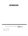
Polarization and Grounding
Like many modern electrical devices, your ENSONIQ product has a three-prong power cord with
earth ground to ensure safe operation. Some products have power cords with only two prongs
and no earth ground. To ensure safe operation, modern products with two-prong power cords
have polarized plugs which can only be inserted into an outlet the proper way.
Non-polarized
Polarized
Three-prong
with earth ground
Some products, such as older guitar amplifiers, do not have polarized plugs and can be
connected to an outlet incorrectly. This may result in dangerous high voltages on the audio
connections, which could cause you physical harm or damage any properly grounded
equipment to which they are connected, such as your ENSONIQ product.
To avoid shock hazards or equipment damage, we recommend the following precautions:
•
•
•
If you own equipment with two-pronged power cords, check to see if they are polarized or
non-polarized. You might consider having an authorized repair station change any nonpolarized plugs on your equipment to polarized plugs to avoid future problems.
Exercise caution when using extension cords or plug adapters. Proper polarization should
always be maintained from the outlet to the plug. The use of polarized extension cords and
adapters is the easiest way to maintain proper polarity.
Whenever possible, connect all products with grounded power cords to the same outlet
ground. This will ensure a common ground level to prevent equipment damage and
minimize hum in the audio output.
AC outlet testers are available from many electronic supply and hardware stores. These can be
used to check for proper polarity of outlets and cords.
ii
ENSONIQ DP/4+ Reference Manual
Preface
AC Line Conditioning
As with any computer device, the DP/4+ is sensitive to sharp peaks and drops in the AC line
voltage. Lightning strikes, power drops, or sudden and erratic surges in the AC line voltage can
scramble the internal memory, and in some cases, damage the unit’s hardware. Here are a few
suggestions to help guard against such occurrences:
•
•
A Surge/Spike Suppressor. The cheaper of the options, a surge/spike suppressor absorbs
surges and protects your gear from all but the most severe over-voltage conditions. You can
get multi-outlet power strips with built-in surge/spike suppressors for little more than the
cost of unprotected power strips, so using one is a good investment for all your electronic
equipment.
A Line Conditioner. This is the best, but by far the more expensive way to protect your gear.
In addition to protecting against surges and spikes, a line conditioner guards the equipment
against excessively high or low line voltages. If you use the DP/4+ in lots of different
locations with varying or unknown AC line conditions, you might consider investing in a line
conditioner.
Guidelines for using the DP/4+
Temperature Guidelines
The DP/4+ contains a substantial amount of computerized and electronic circuitry that can be
susceptible to damage when exposed to extreme temperature changes. When the DP/4+ is
brought inside after sitting in a cold climate (i.e. the back seat of your car), condensation builds
up on the internal circuitry in much the same way a pair of glasses fogs up when you come inside
on a cold day. If the unit is powered up as this condensation occurs, components can short out or
be damaged. Excessively high temperatures also pose a threat to the unit, stressing both the
internal circuits as well as the case. With this in mind, it is highly advisable to follow these
precautions when storing, mounting and setting up your DP/4+:
•
•
•
Avoid leaving the DP/4+ in temperatures of less than 50 degrees Fahrenheit or more than 100
degrees Fahrenheit.
When bringing the DP/4+ indoors after travel, allow the unit at least 20 minutes to reach room
temperature before powering up. In the case of excessive outdoor temperatures (below 50
degrees Fahrenheit or above 100 degrees Fahrenheit), allow an hour or more before power up.
Avoid leaving the DP/4+ inside a vehicle exposed to direct sunlight.
Rack Mounting Guidelines
Because the DP/4+ operates with an internal transformer, there is a certain amount of heat
generated by this unit. For better reliability, we recommend that you do not install this unit
beneath devices that are sensitive to heat, or above power amps, tube equipment, or other rackmount units that emit a lot of heat. We recommend leaving a space above the DP/4+, as well.
ENSONIQ DP/4+ Reference Manual
iii
Preface
Amplifying Your DP/4+ Through a Home Stereo System
If you are thinking about amplifying your DP/4+ through your home stereo, please be careful. A
home stereo is great for playing CDs, albums or tapes — the dynamic range of these media is
limited, and your speakers aren’t usually subjected to extreme volume changes and frequency
transients. While the dynamic range of CDs is significantly greater than LPs or tapes, the output
of a CD player is still conservative compared to output of a pro-level effects processor. Running
your DP/4+ (or any pro-level product) through a home stereo at high volume levels can damage
your stereo system and/or speakers. If your only means of amplification is your home stereo, set
the Level (dBu) switch to the -10 dBV position, set the Output Knobs to around the 12 o’clock
position, and try to keep your levels on the conservative side.
Powering Up Your DP/4+ In a MIDI Configuration
Just as you would power up the individual components before turning on the amplifier in your
home stereo system, you should first turn on the MIDI data transmitting source (processors,
keyboards, modules, etc.) before you power up the receiving MIDI source. For instance, if you’re
using the DP/4+ to receive MIDI information from a keyboard/sequencer, you would turn the
keyboard on before the DP/4+. This will prevent any unwanted MIDI information from being
“spit” out of the transmitting source (keyboard/sequencer) during power up, which could
confuse the MIDI receivers, thereby disabling them. If this should occur, turn off the receiving
module, and then turn it back on.
iv
ENSONIQ DP/4+ Reference Manual
Preface
Reinitializing the DP/4+
If your DP/4+ is behaving in peculiar ways (the display is showing alphanumeric characters that
shouldn’t be there or unexplainable Unexpected Event messages) and a soft reset (or turning the
DP/4+ power off and then on again) won’t cure the problem, try reinitializing the DP/4+.
WARNING!
THIS PROCESS WILL ERASE ALL RAM PRESETS!
The 200 User Presets in the internal memory (RAM) are automatically
loaded with the factory defaults after reinitialization. Good backup
habits should be an important part of your routine. Save any important
information by using the MIDI System Exclusive Dump feature of the
DP/4+, or manually write down the relevant parameters using the
provided Preset Parameter Worksheet (or a photo-copy). If you fail to
do so, you may accidentally lose the presets you’ve created.
To reinitialize the DP/4+
1. While holding down the {SYSTEM"MIDI} button,
2. Press the {B} button.
3. Press the {>} button. The display shows:
01
4.
Hit <WRITE> To
Reinitialize!!!!
Press the {CANCEL} button to quit without reinitializing the system, or
Press the {WRITE} button to reinitialize the DP/4+. Remember that by doing this you will
replace all of the RAM Preset data in the DP/4+, and all System•MIDI parameters will be
reset to their default range!
If reinitializing the DP/4+ does not correct the problem, then contact an Authorized ENSONIQ
Repair Station.
Note: If the DP/4+ is sitting in an infinite loop of system errors (the display is
continually cycling through errors), press the {SYSTEM"MIDI} button to escape this
state.
Note: In the unlikely event of a system malfunction, you can save your entire set-up
(all Preset Banks and System parameters) with a System Exclusive dump by pressing
the {WRITE} button. This will help you restore all of the user-defined parameters. For
more information about System Exclusive dumps, see Section 5 — Storage.
ENSONIQ DP/4+ Reference Manual
v
Preface
Battery Replacement Guidelines
The reason that the DP/4+ “remembers” configs, presets and system parameters, even when the
power is off, is that all of its internal RAM is “battery-backed-up.” The battery that keeps the
DP/4+ memory intact is located inside the DP/4+, and when it becomes discharged, the battery
must be replaced by an Authorized ENSONIQ Repair Station.
The battery that came in your DP/4+ is good for up to five years. You will know when it needs
replacing, because the DP/4+ will tell you so. One day you will switch the power on, and
instead of its usual wake-up message, the display will read:
00
-- WARNING -Battery is Low
This will only appear for a short time, and then you can commence with normal operation. Then,
make sure that all custom RAM configs, presets and system parameters are saved, and take the
DP/4+ to an Authorized ENSONIQ Repair Station as soon as possible to have the battery
replaced.
For more information about saving DP/4+ data, see Section 5 — Storage.
Available Options for Your DP/4+
These optional accessories are available from your Authorized ENSONIQ Dealer:
•
•
CVP-1 Pedal — A Control Voltage Foot Pedal which can be assigned as a modulator to
parameters within the DP/4+. The CVP-1 Pedal makes a great “wah wah” pedal.
SW-10 Dual Damper Foot Switch — Because the DP/4+ has two stereo Foot Switch jacks,
you can use two of these two pedal, piano-type foot switches, for ultimate control! The
pedals can be programmed independently to act as a bypass effect switch, offering two
separately programmable modulation sources or increase/decrease presets.
For a full discussion of these foot switches and how to use them, see Section 1 — Controls &
Basic Functions.
Warning!
The use of single (mono) foot switches is not recommended, and can
affect the operation and performance of the DP/4+.
If you are considering a foot switch for the DP/4+, we strongly recommend purchasing the
SW-10 Dual Foot Switch.
vi
ENSONIQ DP/4+ Reference Manual
Preface
Need More Help?
Whether you’re an aspiring programmer looking for additional information about basic effect
processing techniques and MIDI theory, or a professional sound engineer working with
advanced applications, you may want more detailed information that is beyond the scope of this
manual. The following books can help enhance your understanding of effect processing, MIDI,
and related topics. These, in addition to the numerous monthly magazines, provide a wealth of
information. While we don’t endorse any one of these publications, we offer this partial list as a
resource for you to draw on.
The Mix Bookshelf
For prices and more information call: 1-800-233-9604
MIDI
HOW MIDI WORKS, Dan Walker
MIDI FOR MUSICIANS, Craig Anderton
MIDI SYSTEMS & CONTROL, Francis Rumsey
MIDI, THE INS, OUTS AND THRUS, Jeff Rona
THE MIDI BOOK, Steve De Furia, Joe Scacciaferro
THE MIDI HOME STUDIO, Howard Massey
THE MIDI MANUAL, David Huber
THE MIDI RESOURCE BOOK, Steve De Furia, Joe Scacciaferro
THE NEXT MIDI BOOK, Rychner & Walker
USING MIDI, Helen Casabona, David Frederick
RECORDING
BUILDING A RECORDING STUDIO, Jeff Cooper
DIGITAL DELAYS (And How to Use Them), Douglas Fraser
IMPROVING YOUR SIGNAL PROCESSING SKILLS, (cassette & manual) Bill Gibson
MASTER HANDBOOK OF ACOUSTICS, F. Alton Everest
SOUND RECORDING HANDBOOK, John Woram
SOUND REINFORCEMENT HANDBOOK, Davis & Jones
SYNTHESIS
A SYNTHESIST'S GUIDE TO ACOUSTIC INSTRUMENTS, Howard Massey
MUSIC & TECHNOLOGY, H.P. Newquist
SECRETS OF ANALOG AND DIGITAL SYNTHESIS, Steve De Furia
VIDEOS
SHAPING YOUR SOUND, (video series) Tom Lubin
Alfred Publishing Company
For prices and more information call 1-818-891-5999
MIDI
ADVANCED MIDI APPLICATIONS, GPI
BASIC MIDI APPLICATIONS, GPI
WHAT IS MIDI?, GPI
Hal Leonard Publishing
For prices and more information call 1-414-774-3630
MIND OVER MIDI, GPI
ENSONIQ DP/4+ Reference Manual
vii
Preface
Monthly Magazines
The following magazines offer many specific articles and columns that can provide a plethora of
useful information.
THE TRANSONIQ HACKER
For prices and more information about this independent news magazine for ENSONIQ
Users, call 1-503-227-6848
KEYBOARD
For subscription rates and more information call 1-800-289-9919
ELECTRONIC MUSICIAN
For subscription rates and more information call 1-800-888-5139
HOME & STUDIO RECORDING
For subscription rates and more information call 1-818-407-0744
MIX
For subscription rates and more information call 1-800-888-5139
EQ
For subscription rates and more information call 1-212-213-3444
viii
ENSONIQ DP/4+ Reference Manual
Section 1 — Controls & Basic Functions
There must be
something better…
This section provides an introduction to the DP/4+’s many controls and rear panel connections; a
conceptual overview of the system; a guide to selecting DP/4+ presets; and a discussion of editing
various types of parameters. We suggest you read this section carefully — it will help you get the
most out of your DP/4+.
ENSONIQ DP/4+ Reference Manual
1
Section 1 — Controls & Basic Functions
Mute Outputs
DP/
peak
p a r a l l e
signal
inputs
phones
00.
push
outputs
MIDI
Mic Gain
input 1
inst/mic
1
rear input 1 off
2
3
1
4
2
3
4
5
6
7
Write
Cancel
Copy
Undo
8
9
Front Panel Controls
1. Phones
4. Mute Outputs — (inst/mic)
Plug headphones into this 1/4” stereo jack to listen to the
DP/4+ in stereo. The signal going to this jack is from the
sum of all four rear outputs, even if they are not
connected. The 4 rear outputs are mapped to the stereo
headphone as follows: 1 and 3 are mostly to the left; 2
and 4 are mostly to the right. Headphone volume is
controlled by the Output Knobs. Plugging headphones
into this jack does not turn off the audio in the outputs.
This button is used to mute the rear panel output jacks.
When the LED is on, the output jacks are muted, but the
headphone output remains active.
☞ Warning: The headphone output circuit is designed
to minimize the volume differences between low and
high impedance headphones. Because some
headphones are more efficient than others, set the
Output Knobs accordingly — high output volume levels
could damage your hearing.
2. Input 1 — (inst/mic)
This combination balanced XLR mic/unbalanced 1/4”
mono input jack is for connecting a guitar, microphone,
or any high or low impedance instrument. This jack is
routed to the same input circuitry as the Input 1 jack
located on the rear panel, and is electrically equivalent.
3. Mic Gain — (rear input 1 off)
This activates the XLR Mic (microphone) input and
supplies mic gain to both the Mic and Instrument inputs.
When set to Instrument (LED off):
The XLR Mic Input is disabled.
The 1/4” front panel Instrument input is enabled.
Rear panel Input 1 is overridden and disabled when
the 1/4” front panel Instrument input is connected.
When set to Mic (LED on):
The XLR Mic Input is enabled.
Mic Gain will be supplied to the XLR Mic input.
The 1/4” front panel Instrument input is enabled.
Mic Gain is not supplied to the 1/4” front panel
Instrument input.
Rear panel Input 1 is overridden and disabled.
2
5. Output Knobs
The four Output Knobs control the output level of each
channel. If separate signals are being processed in the
ENSONIQ DP/4+, these knobs will control the “mixdown” volumes. The maximum output level is +19 dBu.
6. Input Knobs
These four input knobs control the gain applied to the
input signals. The input circuitry is designed to work with
signals ranging from -34.6 dBV to +22 dBu. Use these
knobs to set each input to the optimal level for the signal
you are feeding into it.
7. Signal/Peak LEDs
The three LEDs above each knob indicate the level of
the input signal being fed into the Analog-to-Digital
Converters (ADCs).
• The Signal LED (green) will light when a low level
signal (-30dB) is present at the input. Extremely low
level input signals may not trigger this LED.
• The middle LED (yellow) will light at -12dB.
• The Peak LED (red) will light when the incoming
signal reaches -6dB below the ADC clipping point.
For optimal level, adjust the Input Knob so that the
Peak LED flashes only occasionally. Note that the Peak
LEDs indicate the levels of the input signals only and will
not reflect clipping in the digital processing stages.
8. Write•Copy Button
The {WRITE"COPY} button is used to save or copy
presets to the DP/4+’s internal RAM memory.
ENSONIQ DP/4+ Reference Manual
Section 1 — Controls & Basic Functions
/4 +
l
input configurations
e f f e c t s
p r o c e s s o r
1 source
2 source
A
.
B
1
A:Hall Reverb
C
1
2
D
Mix=25 Volume=99
1
3
A
B
1
2
C
D
3
3 source
4 source
1
A
1
1
A
1
2
B
2
2
B
2
C
D
3
3
C
3
3
4
4
D
4
4
on
MIDI
Select
Edit
bypassed
active
System
bypass
all
Compare
10
11
12
13
A
MIDI
14
B
15
C
D
Config
16
17
18
19
9 Cancel•Undo Button
14. System•MIDI Button
The Cancel•Undo button is used to cancel command
functions, return to the selected preset, or to undo your
last unit or system parameter edit.
This is used to view and modify system (or global) and
MIDI parameters.
10. Left and Right Arrow Buttons
The Left and Right Arrow buttons are used to change
parameters except in the Select mode, where they scroll
to the next preset. Also when naming presets, they are
used to change the cursor position within the name.
11. LED Numeric and LCD Display
In Select mode, the red, two-digit LED display shows
the preset number. In Edit and System•MIDI modes,
this display shows the currently active parameter
number. This will also show a “--” when the preset
number is invalid (i.e. when current settings are not
saved).
The yellow, 32-character alphanumeric LCD display
shows you information about parameters, presets and
may also ask you for additional input.
The MIDI Message Indicator (a little red dot in the LED
Display) lights when any MIDI events are received;
useful for troubleshooting MIDI connections.
15. Data Entry Knob
In Select mode, turning the Data Entry Knob will select
presets. In all other modes, the knob will change value
of the currently active parameter. Turning clockwise will
increase and counterclockwise will decrease the values.
16. Unit Buttons
The four Unit buttons (A, B, C, and D) correspond to the
four separate signal processors in the DP/4+. Use
these buttons to activate a particular Unit for selecting
presets or editing parameters. The yellow LED above
each button will light when that Unit is active. When a
Unit button is pressed a second time, it will be bypassed
(the red LED will be lit). Pressing again will reactivate
that Unit.
17. Config Button
This button allows you to select config presets and edit
config parameters. When Config is active, the yellow
LED above the button will be lit. By pressing this button
a second time, you can bypass all four Units (all red Unit
LEDs lit). Pressing this button a third time will reactivate
the Units (no red Unit LEDs lit).
12. Select Button
This is used to select presets which can load effects into
the units and set up signal routing parameters,
depending on the type of preset selected.
18. Power
13. Edit Button
19. Input Configuration LEDs
This is used to edit preset parameters, edit preset titles
and save presets.
One of LEDs above the diagram will be lit, to show the
currently selected input configuration.
ENSONIQ DP/4+ Reference Manual
The power switch turns the DP/4+ on and off.
3
Section 1 — Controls & Basic Functions
Rear Panel Connections
Line
MIDI
Thru
Out
Outputs
In
Foot
Switch 1
Foot
Switch 2
4
CV•Pedal
3
2
mono
1
Level (dBu)
mono
Inputs
4
3
2
mono
1
mono
+4
To reduce the risk of fire or
electric shock do not expose
this product to rain or
moisture.
1
Front panel
Mic Gain
button
disables
rear Input 1
TRS Bal/Unbal
Inputs & Outputs
WARNING!
R
2
3
4
5
R
L
6
7
main
-10
L
8
R
R
L
L
9
1. Line
6. CV•Pedal
The supplied line cord is connected here.
This jack is for connecting an ENSONIQ Model CVP1 Control Voltage Foot Pedal, which is assignable as
a modulator to parameters within the DP/4+.
2. MIDI Thru
“Passes on” all MIDI (Musical Instrument Digital
Interface) information received by the DP/4+ to other
devices. Information generated by the DP/4+ itself
does not go to this jack — the Thru jack merely
echoes what comes in at the MIDI In jack.
Pedal/CV Specs: 3-conductor (tip = control voltage
input, ring = 424. Ohm resistor to +4.25 volts, sleeve
= ground). 110. KOhm input impedance, DC coupled.
Input voltage range = 0 to 4. volts DC. For use with
an external control voltage, use a 2-conductor cable
with the voltage on the tip and the sleeve grounded.
3. MIDI Out
7. Output Jacks
Sends out MIDI information to other instruments and
computers when the System•MIDI parameter “63
Send MIDI PrgChg + Controllers” is set to “ON.”
The four ground compensated output jacks can be
configured in numerous ways. Because the DP/4+
offers fully programmable output control, you can
have almost any combination ranging from a single
mono output to four mixed stereo signals.
4. MIDI In
This jack receives MIDI information from other MIDI
instruments or computers.
5. Foot Switch 1 and 2 Jacks
These two independent foot switch jacks are
designed for dual (stereo) foot switches, and can be
assigned to a number of different functions, allowing a
total of four independent foot switch controllers (when
two optional SW-10 Dual Foot Switches are
connected).
Warning!
The use of single (mono) foot switches is not
recommended, and can affect the operation and
performance of the DP/4+.
See “A note About the Input and Output Jacks” later
in this section.
8. Level Switch
This switch toggles between +4 dBu and -10 dBV (this
affects the rear panel input and output jacks only).
Because this switch can accommodate a broader
range, it allows an improved signal-to-noise ratio.
9. Input Jacks
These four balanced input jacks are truly independent
inputs and can be used in a 1 source, 2 source, 3
source, or 4 source configuration.
See “A note About the Input and Output Jacks” later
in this section.
See “A note About the Foot Switches” later in this
section.
4
ENSONIQ DP/4+ Reference Manual
Section 1 — Controls & Basic Functions
DP/4+ RULES
Setting Levels
The input and output levels affect the volume of audio signal going into and coming out of the
DP/4+, and are controlled by the two rows of four knobs on the left hand side of the front panel.
The top row controls the input levels for Inputs 1 to 4, the bottom row controls the output levels
for Outputs 1 to 4.
Input Knobs
inputs
outputs
1
2
3
4
Output Knobs
Setting the Level Switch
The Level (dBu) switch (found on the rear panel of the DP/4+) toggles between +4 dBu and -10
dBV (this affects the rear panel input and output jacks only). Because this switch can
accommodate a broad range, it allows an improved signal-to-noise ratio. This switch should be
set to match the gain structure of your mixer/amplifier, or particular application. Consult your
product’s manual to determine which is appropriate.
To set the input level(s):
1. With your connections made, send a signal into the DP/4+ and slowly turn the
corresponding Input Knob(s) clockwise. The green Signal LED(s) will begin flashing as soon
as a signal is detected.
2. Turn the Input Knob(s) clockwise until the red Peak LED above the knob begins to flash.
This LED flashes when the peak level is reached, indicating that clipping is about to begin.
3. Turn the Input Knob back down (counterclockwise) just enough so that the red LED no
longer flashes. You have now attained the optimum input signal level.
4. Repeat this process for any additional inputs you have connected.
To set the output level(s):
1. With your connections made and the input level properly set, send a signal into the DP/4+
and slowly turn the corresponding Output Knob(s) clockwise. If you are using a stereo
output, use both outputs 1 and 2. You should begin to hear signal coming through the
DP/4+ into your amplifier, mixer, etc.
2. Continue turning the Output Knob clockwise as far as you can until you hear distortion in
the receiver. To optimize signal-to-noise ratio, it is best to set the output levels of the DP/4+
as high as possible without distortion, turning down the receiving channel if necessary.
3. Turn the Output Knob down (counterclockwise) just enough until there is no distortion.
4. Repeat this process for any additional outputs you have connected.
The DP/4+ circuitry is designed so that if the Input and Output Knobs are set to 12:00 (the lines
in the knobs are pointing up), and you have an input signal of +4 dBu, a +4 dBu signal will go out
of the DP/4+. With the knobs at 12:00, and an input signal of -10dBV, the output of the DP/4+
will also be -10 dBV. With these settings, any incoming signals slightly above +4 dBu or -10dBV
respectively, will result in clipping.
ENSONIQ DP/4+ Reference Manual
5
Section 1 — Controls & Basic Functions
Using Headphones with the DP/4+
Headphones can be used with the DP/4+ when connected to the front panel 1/4” stereo Phones
jack to listen to the DP/4+ in stereo. The signal going to this jack is from the sum of all four rear
outputs, even if they are not connected. The 4 rear outputs are mapped to the stereo headphone
as follows: 1 and 3 are mostly to the left; 2 and 4 are mostly to the right. The outputs are not
routed hard left and right, to provide a “mixed stereo” signal:
Left Ear Hears
Outputs 1 & 3 - mostly
Right Ear Hears
Outputs 2 & 4 - mostly
Outputs 2 & 4 - a little
Outputs 1 & 3 - a little
Headphones
Headphone volume is controlled by the Output Knobs. Plugging headphones into the Phones
jack does not turn off the audio in the outputs. Remember to turn up the Output Knobs in pairs
(1 and 2, 3 and 4) in order to preserve the stereo image. Depending on the rear panel
connections, you may need to turn up Outputs 3 and 4.
☞ Warning: The headphone output circuit is designed to minimize the volume differences
between low and high impedance headphones. Because some headphones are more efficient
than others, make sure you set the Output Knobs accordingly — high output volume levels
could damage your hearing.
6
ENSONIQ DP/4+ Reference Manual
Section 1 — Controls & Basic Functions
The Input 1 Jack — Front Panel vs. Back Panel
The following diagrams show how the front panel Input 1 jack (along with the {MIC_GAIN}
button) affects the rear panel Input 1 jack.
With a 1/4” phone plug connected to the front panel Input 1 jack, and the Mic Gain LED on:
The front panel Input 1 works — the rear panel Input 1 doesn’t work:
Mic Gain
push
Inputs
1
mono
input 1
inst/mic
rear input 1 off
With a 1/4” phone plug connected to the front panel Input 1 jack, and the Mic Gain LED off:
The front panel Input 1 works — the rear panel Input 1 doesn’t work:
Mic Gain
push
Inputs
1
mono
input 1
inst/mic
rear input 1 off
With an XLR cable connected to the front panel Input 1 jack, and the Mic Gain LED on:
The front panel Input 1 works — the rear panel Input 1 doesn’t work:
Mic Gain
push
Inputs
1
mono
input 1
inst/mic
rear input 1 off
With an XLR cable connected to the front panel Input 1 jack, and the Mic Gain LED off:
The front panel Input 1 doesn’t work — the rear panel Input 1 works:
push
Mic Gain
Inputs
1
mono
input 1
inst/mic
rear input 1 off
L
With nothing connected to the front panel Input 1 jack, and the Mic Gain LED on:
The front panel Input 1 doesn’t work (nothing’s plugged into it) — the rear panel Input 1 doesn’t work:
push
Mic Gain
Inputs
1
mono
input 1
inst/mic
rear input 1 off
L
With nothing connected to the front panel Input 1 jack, and the Mic Gain LED off:
The front panel Input 1 doesn’t work (nothing’s plugged into it) — the rear panel Input 1 works:
push
Mic Gain
Inputs
1
mono
input 1
inst/mic
ENSONIQ DP/4+ Reference Manual
rear input 1 off
L
7
Section 1 — Controls & Basic Functions
A Note About the Input and Output Jacks
Use standard balanced (TRS stereo cables) or unbalanced (TS mono cables) for these connections.
If there is a problem with hum or buzz, see the following section on ground loops.
Outputs
4
3
mono
2
1
Level (dBu)
mono
Inputs
4
3
mono
2
1
mono
+4
Front panel
Mic Gain
button
disables
rear Input 1
TRS Bal/Unbal
Inputs & Outputs
R
L
R
Output Jacks
main
-10
L
R
L
R
L
Input Jacks
As the labels on the Input and Output jacks indicate, the DP/4+ employs extensive automatic
switching on each stereo pair of inputs and outputs. That is:
•
Normally, Inputs 1 and 2, and Inputs 3 and 4 are treated as stereo inputs. However, if
nothing is plugged into 2 or 4, Inputs 1 and 3 will work as mono inputs and will also provide
signal to Inputs 2 and 4 respectively.
Note: In some cases, you may not want to have the mono signal plugged into Inputs
1 and/or 3 sent to Inputs 2 and/or 4. To send a discrete mono signal to Input 1 and/or
3, connect a “dummy” cable into the Input 2 and/or 4 jack (a dummy cable is just a
standard balanced/unbalanced cable that is not connected to any external device).
•
•
Similarly, Outputs 1 and 2, and Outputs 3 and 4 are normally stereo outputs. If nothing is
plugged into Outputs 2 or 4, however, the stereo signal will be summed to mono and sent to
Outputs 1 and 3 respectively.
If nothing is plugged into Output 3, the stereo signals from outputs 3 and 4 will be summed
with the stereo signal from outputs 1 and 2 before the automatic switching circuit described
above.
Note: In some studio applications (such as when using a patch bay), you may want to
have outputs 3 and 4 connected, and still have the stereo signals from outputs 3 and 4
summed with the stereo signal from outputs 1 and 2. There is a parameter in
System•MIDI mode that allows you to accomplish this (parameter #60, Mix Output 3/4
onto 1/2). See Section 4 — System•MIDI for more information about this parameter.
8
ENSONIQ DP/4+ Reference Manual
Section 1 — Controls & Basic Functions
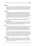
Ground Loops
Sometimes currents flowing through the ground line generate a signal seen by another part of the
circuit sharing the same ground. In other words, if there are two identical signal paths within a
circuit, they can form a loop which can result in hum and/or noise. If you are using equipment
that has 3-prong “grounded” AC power cords, you may suffer from a ground loop resulting from
the interconnection of this equipment. The following diagram shows how cascading or
“chaining” the output of one 3-prong grounded system into the input of another 3-prong
grounded system with a standard, unbalanced 2 conductor cord (like a 1/4” guitar cable) can
result in a ground loop.
Unbalanced Output to Unbalanced Input.
Single conductor shielded cable
SIGNAL PATH
3-Prong
"Grounded"
System
+
+
Unbalanced Output to Unbalanced Input.
Single conductor shielded cable
SIGNAL PATH
3-Prong
"Grounded"
System
3-Prong
"Grounded"
System
2-Prong
+
(circuit ground)
>
+"UNGrounded"
System
(circuit ground)
Ground Loop
<
Earth Ground
Earth Ground
FIG. 1
FIG. 2
Fig. 1 shows a system interconnection where a ground loop can exist. Fig. 2 shows a system
interconnection where a ground loop does NOT exist.
The DP/4+ has “ground compensated” outputs, which offer the advantages of balanced outputs
(minimized hum and interference), plus the advantage of a transformer isolated output
(eliminates ground loop problems). The output connector “grounds” are not hooked directly to
the DP/4+ ground, thus eliminating the ground loop. This ground compensating scheme works
on both balanced and unbalanced equipment with standard cables.
Ground loops are possible only on the inputs, and only in the following situations:
1. When a standard balanced cable is used from the preceeding piece of equipment (i.e., a
standard stereo cable).
Standard Balanced Cable
T
R
S
2.
Red
Black
Shield
T
R
S
When a standard unbalanced cable is used from the preceeding piece of equipment.
Standard Unbalanced Cable
Red
T
S
Shield
T
S
This does not mean there will always be an input ground loop problem, just the possibility.
ENSONIQ DP/4+ Reference Manual
9
Section 1 — Controls & Basic Functions
If it exists, input ground loops can be eliminated in the following ways:
1. In balanced applications, disconnect the shield from the connector that is plugged into the
output of the source device.
Custom Balanced Cable (to eliminate input ground loop)
Red
Black
Shield
T
R
(unconnected)
OTHER 1/4" output (balanced)
2.
T
R
S
ENSONIQ 1/4" input (balanced)
In unbalanced applications, use a special cable with the shield disconnected from the
connector that is plugged into the source device. Attach the source device’s ground to the
ring of the DP/4+ input connector. The two tips connect normally.
Custom Unbalanced Cable (to eliminate input ground loop)
Red
Black
Shield
T
S
(unconnected)
OTHER 1/4" output (unbalanced)
3.
T
R
S
ENSONIQ 1/4" input (balanced)
An audio isolation transformer will fix both balanced and unbalanced input ground loop
problems, as long as the two grounds do not connect. Many of these devices have a switch
on the unit that can either connect or disconnect the grounds ( a ground lift switch).
Using XLR Ins and Outs with the DP/4+
The DP/4+ ground compensating outputs make things very easy. Use of a standard 1/4” to XLR
cable will work fine with no ground loops.
1/4" to XLR Balanced Cable
Red
Black
Shield
T
R
S
3
1
2
Case
ENSONIQ 1/4" output
3-Pin XLR male input
(ground compensated)
(balanced)
As with the 1/4” to 1/4” input connections, the XLR to 1/4” cables can create some problems.
Ideally, the connection of the case and pin 1 of the XLR output jack would be standard.
Unfortunately, they are not. If you have an input ground loop problem with an XLR to 1/4”
cable, the solutions are as follows:
1.
Disconnect the cable shield from pin 1 and the case connection as shown below:
Custom XLR to 1/4" Balanced Cable
3
1
Case
2
(unconnected)
Red
Black
Shield
3-Pin XLR female output (balanced)
2.
T
R
S
ENSONIQ 1/4" input (balanced)
Use an audio isolation transformer.
If all audio equipment adopted this input/output scheme, ground loops would be a thing of the
past.
10
ENSONIQ DP/4+ Reference Manual
Section 1 — Controls & Basic Functions
A Note about the Foot Switches
Line
MIDI
Thru
Out
In
Foot
Switch 2
Foot
Switch 1
WARNING!
To reduce the risk of fire or
electric shock do not expose
this product to rain or
moisture.
The recommended foot switch for use with the DP/4+ is the ENSONIQ Model SW-10 Dual Foot
Switch. The SW-10 is a dual (piano-type) foot switch with two separate pedals. When the SW-10
is connected, the pedals can each be programmed independently to act as effect bypass switches,
to provide two separately programmable modulation sources or to select presets.
The SW-10 is a
stereo Foot Switch
and has a
Stereo Plug
SW-10
Warning!
The use of single (mono) foot switches is not recommended, and can
affect the operation and performance of the DP/4+.
If you are considering using a foot switch, we strongly recommend the ENSONIQ SW-10 Dual
Foot Switch.
About Mono Foot Switches
The DP/4+ is designed with two stereo foot switch jacks. When any mono foot switch is plugged
in, it functions like the right side of a stereo foot switch, and will act as a permanent shut-off
switch for the (non-existent) left side of the foot switch. Many of the quick steps for getting
around on the DP/4+ require two simultaneous button presses, and will not work properly
because the DP/4+ reads the left foot switch connection as constantly engaged (as if a button is
permanently pressed in).
If you have two mono foot switches connected, the DP/4+ will assume that two button presses
(the left sides for each foot switch) are continually engaged, and the DP/4+ will not function at all
(it will appear to be broken).
If a mono foot switch is connected to the Foot Switch 1 jack, and the DP/4+ power is switched
on, you will briefly see “Button #14” in the display. If a mono foot switch is connected to the
Foot Switch 2 jack, and the DP/4+ power is switched on, you will briefly see “Button #15” in the
display.
If you must use a mono foot switch, please consider performing one of the two modifications explained in
“HOT MODS,” found later in this section.
ENSONIQ DP/4+ Reference Manual
11
Section 1 — Controls & Basic Functions
Four-On-The-Floor
An Application For Using Two Stereo Foot Switches to Bypass Effects
The DP/4+ allows you to employ two stereo foot switches (such as the ENSONIQ SW-10) to turn
the DP/4+’s four effects processors on and off. To set up your foot pedals:
1. Connect one foot pedal to the Foot Switch 1 jack on the DP/4+’s back panel.
2. Connect the other foot pedal to the Foot Switch 2 jack.
3. Physically place the two foot pedals side-by-side, with the first to the left of the other.
Foot Switch
1-L
Foot Switch
1-R
Foot Switch
2-L
Foot Switch
2-R
4.
5.
Press the {SYSTEM"MIDI} button on the DP/4+’s front panel.
Press the {>} or {<} button until the large red number reads “06” and the top line of the
display shows “Unit A Bypass=.”
6. Turn the large silver Data Entry Knob to dial in “Ftsw 1-L Toggle.”
7. Press {>} until the red number shows “13” and the display reads “Unit B Bypass=.” Dial in
“Ftsw 1-R Toggle.”
8. Press {>} until the red number shows “20” and the display reads “Unit C Bypass=.” Dial in
“Ftsw 2-L Toggle.”
9. Press {>} until the red number shows “27” and the display reads “Unit D Bypass=.” Dial in
“Ftsw 2-R Toggle.”
Each foot switch is now assigned to its own processor:
turns Unit A
on and off
turns Unit B
on and off
turns Unit C
on and off
turns Unit D
on and off
Note: Whether it’s the effect being added to a sound (bypass/unbypass) — or the
sound itself (kill/unkill) —is determined by each Unit’s “(b)ypass and (k)ill” setting.
See the description of the Bypass/Kill parameter in Section 3—Config Parameters for
more information.
12
ENSONIQ DP/4+ Reference Manual
Section 1 — Controls & Basic Functions
HOT MODS!
Although they are not recommended, mono foot switches such as the ENSONIQ Models SW-2 or
SW-6 Foot Switches can be used successfully if you are willing to make either of the following
modifications. If you are not comfortable performing the following modifications, we
recommend asking a qualified technician for assistance:
Replace the Mono Foot Switch Plug with a Stereo Plug
The advantage of this modification is that you will eliminate the “shorted” left foot switch signal
(see “About Mono Foot Switches” earlier).
Before
After
Ring
Sleeve
Tip
Tools/supplies required:
soldering iron
solder
wire cutters
1/4” stereo plug
1.
2.
3.
4.
5.
Unscrew the mono plug cover, and slide it out of the way (down the cable).
Either with wire cutters or a soldering iron, remove the wires from the mono plug.
Replace the mono plug cover with the stereo plug cover on the mono foot switch cable.
Solder the “hot” wire (the insulated wire in the center of the cable) to the tip connector, and
the ground (shield) wire to the sleeve on the stereo plug as shown in the diagram.
Screw the stereo plug cover onto the stereo plug to complete the modification.
ENSONIQ DP/4+ Reference Manual
13
Section 1 — Controls & Basic Functions
HOT MODS!
Build a Splitter Box to Merge Two Mono Foot Switches into One Stereo Jack
The advantage of this modification is that you it will allow you to make two mono foot switches
function as one stereo foot switch.
Stereo cable needed from here to
either DP/4+ Foot Switch jack
Stereo Jack
Ring
Sleeve
Tip
Tip
Mono Jack
Left mono foot switch
Tip
Sleeve
Sleeve
Mono Jack
Right mono foot switch
Tools/supplies required:
soldering iron
solder
wire cutters
drill and drill bits
one plastic housing assembly (must be large enough to mount three jacks)
one stereo jack
two mono jacks
shielded wire
1/4” stereo-to-stereo cable
1.
2.
3.
4.
5.
6.
7.
Drill three holes in the housing assembly and mount the stereo and mono jacks.
Solder a wire from the tip of the left mono jack to the ring of the stereo jack.
Solder a wire from the tip of the right mono jack to the tip of the stereo jack.
Solder a wire(s) connecting the sleeves of all three jacks.
Connect the mono foot switch(es) to the mono jacks.
Connect the stereo-to-stereo cable between the stereo jack and either DP/4+ Foot Switch jack.
You might want to mark the housing assembly to easily identify the jacks.
Tip: By doubling the above instructions, you could build a splitter box to merge four
mono foot switches into two stereo jacks, for maximum DP/4+ control!
14
ENSONIQ DP/4+ Reference Manual
Section 1 — Controls & Basic Functions
DP/4+ Modes
The DP/4+ will always be in one of three different modes: Select, Edit, or System•MIDI. You
enter one of these modes by pressing its button on the front panel; the current mode is indicated
by which LED is lit.
Select Mode
Select
Edit
System
Compare
MIDI
Edit Mode
Select
Edit
System
Compare
MIDI
Press the {SELECT} button to enter Select mode. Its LED will light. In this mode,
you select Presets. These can be 1 Unit, 2 Unit, 4 Unit, or Config Presets,
depending on the current configuration.
In Select mode, presets can also be copied to new locations by pressing the
{WRITE} button, and is explained in detail in Section 5 — Storage.
Press the {EDIT} button to enter Edit mode. Its LED will light. In this mode, you
can edit (change the settings of) presets, the algorithm (effect) in each of the four
Units ({A}, {B}, {C}, or {D}) and its related parameters, and the config parameters
(how the signals are routed). Edit Mode is the easiest place to change the
algorithm (by selecting a 1 Unit preset) in a single unit.
In Edit mode, presets that have been edited can be saved by pressing the {WRITE}
button, and is explained in detail in Section 5 — Storage.
For specific information about the Algorithms and their related parameters, see
Section 2 — Algorithms. For more information about the Config parameters, see
Section 3 — Config Parameters.
System•MIDI Mode
Select
Edit
System
Press the {SYSTEM"MIDI} button to enter System•MIDI mode. Its LED will light.
In this mode, you can edit MIDI parameters, and parameters which are systemwide, or “global.” The System•MIDI parameters do not change when you select
different presets and configs.
For specific information about the System•MIDI parameters, see Section 4 —
System•MIDI.
Compare
MIDI
In System•MIDI mode, pressing the {WRITE} button will access the MIDI System
Exclusive (SysEx) data transfer function for storage of DP/4+ presets and system
parameters.
For information about using SysEx to store DP/4+ data, see Section 5 — Storage.
Button Names
Throughout this manual, when we refer to an actual button, it will appear as a “button” in the
text. For example, if the text read something like “press the Edit button,” it would appear as
“press the {EDIT} button.” This will help you to quickly skim through familiar sections of the
manual as you verify actual button presses.
ENSONIQ DP/4+ Reference Manual
15
Section 1 — Controls & Basic Functions
About Select Mode
In Select mode, you select Presets. These can be 1 Unit, 2 Unit, 4 Unit, or Config Presets,
depending on the current config and on which unit buttons ({A}, {B}, {C}, or {D}) have been
pressed after pressing the {SELECT} button.
Input Configuration type:
What type of presets you can select:
1 source configuration
4-Unit Presets
2 source configuration
2-Unit Presets
3 source configuration
two 1-Unit Presets and one 2-Unit Preset
4 source configuration
four 1-Unit Presets
In this mode, the display shows the selected preset’s number, name, unit algorithm(s), the
currently selected unit and the signal routing. The Data Entry Knob and the {<} and {>} buttons
select new presets.
00
i
Preset Number
•
•
•
Preset Name Here
cmp~REV+ddl⁄ddl
i
i
Algorithm and signal routing information
The red LED display (on the left) shows the preset’s location within the DP/4+ memory. If
any parameters have been edited (changed) within this preset, this display will show “- -.”
The top line of the LCD display (on the right) shows the presets name.
The bottom line shows which algorithm (effect) is in each unit as well as signal routing
information, depending on the current configuration.
In a 2 Unit, or 4 Unit preset, you will notice that one of the abbreviations in your display is
capitalized. This shows that the capitalized algorithm is located in the currently selected unit (in
the diagram above, it’s Unit B). If none of the algorithm abbreviations are capitalized, it means
that the Config is activated. Try pressing the different Unit buttons ({A}, {B}, {C}, and/or {D})
to see the abbreviations change between lower case and upper case. When you press the
{CONFIG} button, there are no capitalized algorithm abbreviations.
When a unit is selected by pressing its Unit button ({A}, {B}, {C}, or {D}):
• its algorithm abbreviation is capitalized
• that unit will be selected for editing, if you press the {EDIT} button.
• pressing its button again will bypass the unit (its red LED will light)
16
ENSONIQ DP/4+ Reference Manual
Section 1 — Controls & Basic Functions
About Edit Mode
In Edit mode, you can edit (change the settings of) presets, the algorithm (effect) in each of the
four Units ({A}, {B}, {C}, or {D}) and its related parameters, and the config parameters (how the
signals are routed). Edit Mode is the easiest place to change the algorithm (by selecting a 1 Unit
preset) in a single unit.
After pressing {EDIT}, pressing ({A}, {B}, {C}, or {D}) or {CONFIG} determines what you will
be editing. The display shows:
01
i
Parameter Number
•
•
•
•
A:Small Room Rev
Mix=48 Volume=99
i
i
Parameters which can be selected and adjusted
The red LED display (on the left) shows the number of the currently selected parameter. This
will change as you press the {<} and {>} buttons (called scrolling) to select different
parameters.
When the algorithm name is selected, the red LED display will flash to differentiate it from
the other parameter numbers. The number displayed will show the number of the 1 Unit
Preset that will next be selected when the knob is turned.
The LCD display (on the right) shows one or more parameters, which can be selected and
adjusted. The currently selected parameter will always be flashing.
The Data Entry Knob is used to change the value of the selected parameter.
Edit Buffer
As soon as you change a parameter’s value, you will notice that the Edit LED begins flashing.
This means that you are now listening to a modified version of the algorithm in the Edit Buffer.
The Edit Buffer is a section of RAM where edits are temporarily stored.
By pressing the {EDIT} button you can toggle between the original setting (LED solidly lit) and
the newly edited version (LED flashing) of that algorithm. What is visible on the display is the
parameter settings that you hear.
ENSONIQ DP/4+ Reference Manual
17
Section 1 — Controls & Basic Functions
About System•MIDI Mode
In System•MIDI mode, you can edit unit-specific MIDI parameters, and parameters which are
system-wide, or “global.” The System•MIDI parameters (such as MIDI channels, Controllers,
and program change maps) do not change when you select different presets and configs.
For specific information about the System•MIDI parameters, see Section 4 — System•MIDI.
To enter System•MIDI mode, press the {SYSTEM"MIDI} button. The display shows:
Parameter Number
m
54
Parameter Name
m
Preset Memory
Protect=Off
i
Parameter range which can be selected and adjusted
•
•
•
•
The red LED display (on the left) shows the number of the currently selected parameter.
There are 67 parameters in this mode.
The LCD display (on the right) shows one or more parameters, which can be selected and
adjusted. The currently selected parameter will always be flashing.
The {<} and {>} buttons scroll through the different parameters. Use them to select the
parameter you want to change.
The Data Entry Knob changes the value of the selected parameter.
Tip: Though you can scroll continuously through all 67 System•MIDI parameters
using the {<} and {>} buttons, this might get tedious; you can use the following
shortcuts to get close to the parameter(s) you desire:
•
•
18
After pressing {SYSTEM"MIDI}, press {A}, {B}, {C}, {D}, or {CONFIG} to go to unit-specific
MIDI parameters relating to them.
Press {SYSTEM"MIDI} repeatedly to go directly to several convenient locations within the
remaining parameter list. Then scroll to the parameter you want.
ENSONIQ DP/4+ Reference Manual
Section 1 — Controls & Basic Functions
About Presets
The DP/4+ has 400 presets in its memory, but you can’t get to all of them at any one time. This is
because:
•
•
100 of the presets are Config presets which change the input configuration and routing as
well as load new effects algorithms; and
of the remaining 300 presets, the type(s) of presets available for viewing and selecting
depends on the current config type.
Input Configurations
The diagram in the upper right corner of the DP/4+ shows the input configurations. All of the
DP/4+ input configurations are based on this diagram:
input configurations
1 source
A
1
B
1
C
2
D
2 source
1
3
A
B
1
2
C
D
3
4
3 source
4 source
1
A
1
1
A
1
2
B
2
2
B
2
C
D
3
3
C
3
3
4
4
D
4
One Source Input Configuration
In a 1 Source Config, the LED above the 1 source input configuration diagram will light. Use
Input 1 for a mono signal (such as a guitar), or Inputs 1 and 2 if your source is a stereo signal
(such as a keyboard). The choice of stereo or mono for an input is a 1 Source Config parameter,
and will be covered later. Remember, any mono signal (high or low impedance) can be plugged
into the jack on the front panel. The Input 1 jack (front panel) will always override the Input 1
jack on the rear panel.
Two Source Input Configuration
In a 2 Source Config, the LED above the 2 source input configuration diagram will light. For
your first source, use Input 1 for a mono signal, or Inputs 1 and 2 if your source is a stereo signal.
For your second source, use Input 3 for a mono signal, or Inputs 3 and 4 if your second source is a
stereo signal. You can choose a stereo or mono input selection for Inputs 1 and 2 and/or Inputs 3
and 4 using the appropriate 2 Source Config parameters.
Three Source Input Configuration
In a 3 Source Config, the LED above the 3 source input configuration diagram will light. Use
Inputs 1 and 2 for two independent mono signals. For your third source, use Input 3 for a mono
signal (such as a guitar or a microphone), or Inputs 3 and 4 if your source is a stereo signal. The
choice of stereo or mono for Inputs 3 and 4 is a 3 Source Config parameter.
Four Source Input Configuration
In a four source config, the LED above the 4 source input configuration diagram will light. Four
separate mono sources are plugged into Inputs 1, 2, 3, and 4.
ENSONIQ DP/4+ Reference Manual
19
Section 1 — Controls & Basic Functions
Selecting Config Presets
Of the four Preset types, the most powerful is the Config Preset. The Config preset lets you save,
and later recall, the current state of the DP/4+, including all algorithm, signal routing and mixing
information.
Selecting a Config preset will
• Reconfigure the DP/4+ inputs and outputs;
• Change the signal routing between units; and
• Load a new algorithm into each of the four Units.
To select a Config preset
1. Press {SELECT}.
2. If the Config LED is not already on, press {CONFIG}.
3. Move the large silver Data Entry Knob, or press the {<} and {>} buttons. The Select LED
flashes, indicating that you are previewing presets. The display shows the available Config
presets.
4. When the display is showing the preset you want to load, press {SELECT} again. This selects
the preset, and the Select LED stops flashing.
Note: The first 10 ROM Config locations (presets #50 to 60) can be used as “starting
places” for creating your own configurations, and cover common signal routing set-ups.
20
ENSONIQ DP/4+ Reference Manual
Section 1 — Controls & Basic Functions
How the Config Type Affects Selecting Presets
The four different config types effectively turn the DP/4+ into 1, 2, 3, or 4 independent effects
processors, with a varying number of DP/4+ effects units per “processor”:
Configuration type:
A
B
C
Preset Example (s):
D
A 1 source config turns the DP/4+ into one
giant multi-effects processor, with four
effects units all processing the same input
signal. These are called 4-Unit Presets.
A
B
C
D
A 2 source config turns the DP/4+ into
two multi-effects processors, with two
effects units applied to each input signal.
These are called 2-Unit Presets.
A
B
C
D
A 3 source config turns the DP/4+ into
three effects processors; two with one
effects unit a piece (A and B), and one
with two effects units (C and D). Units A
and B select 1-Unit Presets, and Units C
and D select 2-Unit Presets.
A
B
C
D
A 4 source config turns the DP/4+ into four
independent effects processors; each of
the four Units processes a different input
signal and is treated as a separate device.
Crystal Cave CMP~fla+pit⁄rev
In a 4-Unit Preset, the lower line of the
display shows the 3-letter abbreviations for
the algorithms in all 4 units. A 4-Unit Preset
will load new algorithms into all four units.
Airplane Hangar A:REV ~ B:rev
In a 2-Unit Preset, the lower line shows the 3letter abbreviations for the algorithms in both
units, and indicates which 2 units the preset
will be loaded into (A&B or C&D).
Vocal Plate 1 A:Large Plate
Airplane Hangar A:REV ~ B:rev
In a 1-Unit Preset, the
lower line of the display
shows the full name of the
algorithm in the preset,
and indicates which unit
the preset will be loaded
into (A or B).
In a 2-Unit Preset, the
lower line shows the 3letter abbreviations for the
algorithms in both units,
and indicates which 2 units
the preset will be loaded
into (A&B or C&D).
Vocal Plate 1 A:Large Plate
In a 1-Unit Preset, the lower line of the display
shows the full name of the algorithm in the
preset, and indicates which unit the preset will
be loaded into (A, B, C, or D).
If you think of the outer grey boxes shown above as different “processors,” you’ll notice that each
of these configs creates a number of “processors” that are either 1, 2, or 4 Units combined. This
determines what presets you can select at any given time. The DP/4+ has 1 Unit, 2 Unit, and 4
Unit presets, and you can only select presets of the type(s) allowed by the current config.
There are two ways that the DP/4+ shows you which type of preset you are selecting:
1.
2.
In Select mode, when you press any of the Unit buttons ({A}, {B}, {C}, or {D}), either 1, 2, or
4 of the yellow Unit LEDs will light. The number of lighted LEDs corresponds to the type of
preset you will be selecting if you move the Data Entry Knob. The yellow Unit LEDs also tell
you which unit(s) will be loaded with a new algorithm if you select a new preset.
The display gives you constant feedback. For all preset types, the upper line of the display
shows the preset name. The lower line shows how many units are in the preset you are
selecting.
ENSONIQ DP/4+ Reference Manual
21
Section 1 — Controls & Basic Functions
Replacing the Algorithm in a Single Unit
You can use Edit mode to easily replace the algorithm in one of the four units without changing
the current config or affecting what is in the other units.
To replace the algorithm in a unit:
1. Press {EDIT}.
2. Press Unit {A}, {B}, {C}, or {D} to select that unit for editing. The active unit’s yellow LED
should be lit. The display shows:
Unit Preset Number flashing
m
50
3.
Selected Unit
m
Algorithm Select (flashing)
m
A:Algorithm Name
Mix=48 Volume=99
The red LED display should flash, indicating the number of the unit preset last selected. The
algorithm name should be flashing in the upper line of the LCD display. If neither is
flashing, press the {<} button until this is the case.
Move the Data Entry Knob to select among the algorithms in memory. The display will
change, showing the algorithm name on the top line, and the name of the 1 Unit preset that
uses the algorithm on the bottom line. When you stop moving the knob, the algorithm that is
showing on the display will be loaded into the Unit, and the display will change back to the
one shown above.
Note: When you select algorithms in Edit mode, you are actually picking from the list
of 100 1-Unit presets. As you are moving the knob, the red LED display shows the
preset numbers of the 1 Unit presets you are loading into the unit. One second after
you’ve stopped moving the knob, the algorithm is loaded into the unit and the red LED
display will flash the preset number selected.
4.
To change the algorithm in another unit, simply press its unit button and repeat the above
steps. Note that selecting a unit which is already active causes it to become bypassed. The
red bypass LED for that unit will light. Further presses toggle out of and into bypass.
Note: If you accidentally edit the algorithm in a unit, you will lose all of the
parameter settings for the old algorithm unless you press {UNDO} to recall the original
algorithm and its parameters. You must press {UNDO} before scrolling to another
parameter or leaving Edit mode.
Loading a 2 Unit Preset While in a 1 Source Config
When you are using the DP/4+ in a 1 Source Config (where you can only select 4 Unit Presets) it
is possible to load the effects combination from a 2 Unit preset (or a 2 Unit algorithm) into A & B
or C & D. Here’s how:
1.
2.
3.
22
Press {EDIT} (if you are not already in edit mode).
Press either the {A} and {B}, or {C} and {D} buttons at the same time. Both LEDs will light
up.
Move the Data Entry Knob to display the 2 Unit preset you desire, wait a moment and it will
load automatically.
ENSONIQ DP/4+ Reference Manual
Section 1 — Controls & Basic Functions
About Signal Routing
The four audio inputs are analog signals which are fed to four analog-to-digital converters. The
four units are digital audio signal processors which have digital inputs and outputs. Routing
between the units is digital. The output of a unit is converted back to analog audio for the output
jack.
Inputs
Analog-toDigital
Converters
1
A/D
2
Units
Digital-toAnalog
Converters
Outputs
A
D/A
1
A/D
B
D/A
2
3
A/D
C
D/A
3
4
A/D
D
D/A
4
= Analog
= Digital
(Not all of the possible signal routings are shown.)
All of the above elements are under complete software control.
Signal Routing Between Units
Depending of the current Config, the four units can be connected to each other in one of five
different ways, which are depicted with five different symbols. The routing symbols (shown
between each algorithm in Select mode) are:
00
Preset Name Here
01
Two Cool Effects
cmp~REV+ddl⁄fla
pit*pit cho~pan
~
Indicates a serial connection from the unit on the left into the unit on the right. The top
example shows a serial connection from Unit A into Unit B.
+
Indicates a parallel connection between the unit on the left and the unit on the right. The
top example shows this between Unit B and Unit C.
⁄
Indicates a feedback 1 connection from the unit on the right back into the unit on the left.
The top example shows a feedback 1 connection from Unit D back into Unit C.
Indicates a feedback 2 connection from the unit on the right back into the unit on the left.
*
(blank space)
Indicates that the two units are “ganged together” using an algorithm that requires more
than one unit of processing power (for instance the PitchShift 2U algorithm). The
routing between units cannot be modified as long as such a “ganged” 2 Unit algorithm is
active. The bottom example shows this between Units A and B.
Indicates that there is no connection between units, and that they are routed separately
(the blank space will not appear in a 1 Source Config, because all four units are always
connected together). The bottom example shows that there is no connection between
Unit B and Unit C; signifying that this is a 2 source configuration.
ENSONIQ DP/4+ Reference Manual
23
Section 1 — Controls & Basic Functions
Understanding Serial, Parallel and Feedback Signal Routing
When we speak of connecting units together, we are usually referring to one of three types of
signal routing, serial, parallel, or feedback. It is very important to understand the difference
between these concepts.
Serial Routing
Serial routing means the input signal is routed through the first unit before being sent to the input
of the second unit.
This is a serial signal routing between two units:
Input
Signal
1st
Unit
2nd
Unit
Output
Signal
If, for example, the first unit is a chorus, and the second a reverb, you have the signal first going
through the chorus, then into the reverb. As a result, you would hear the chorused sound with
reverb applied to it.
Parallel Routing
Parallel routing means the same input signal is routed separately to inputs of both units, and then
their outputs are mixed together.
This is a parallel signal routing between two units:
1st
Unit
Input
Signal
+
2nd
Unit
Output
Signal
In this example, if the first unit is a chorus, and the second a reverb, you would hear the chorused
sound and a sound with reverb, but the chorused sound would not have reverb on it, and the
sound coming out of the reverb would not have chorusing.
Feedback Routing
Feedback routing (shown by a ⁄ symbol) is similar to serial routing, with the addition of a
feedback signal. See Section 3 — Config Parameters for more on feedback routing.
This is a feedback signal routing between two units:
Input
Signal
1st
Unit
2nd
Unit
Output
Signal
In this example, if the first unit is a chorus, and the second a reverb, you have the signal first
going through the chorus, then into the reverb. There is then an additional tap that sends the
processed signal back into the beginning of the first unit (the chorus).
24
ENSONIQ DP/4+ Reference Manual
Section 1 — Controls & Basic Functions
Bypassing Units
At some point while you’re selecting various 4 Unit Presets, you may want to listen to how an
individual unit’s effect is processing the incoming audio signal. In this case, you would need to
bypass the other three units.
To bypass a single unit’s algorithm:
1. Press the unit button ({A}, {B}, {C}, or {D}) that you want to bypass.
2. Press the same unit button again. The red LED above the unit button will be lit, and the unit
will be bypassed.
3. Further presses of the unit button will toggle out of and into bypass.
To completely bypass all of the unit algorithms:
1. Press the {CONFIG} button.
2. Press the {CONFIG} button again. All of the red LEDs above the units will be lit, and the
units will be bypassed.
3. Further presses of the {CONFIG} button will toggle all four units out of and into bypass.
Refer to the description of the Bypass/Kill parameter in Section 3 — Config Parameters for more
information.
Note: Units can also be bypassed, un-bypassed, and killed remotely with MIDI
Program Changes by enabling the unit’s MIDI Program Change Map. See Section 4 —
System•MIDI for more information.
Quick Tips and Shortcuts
Here are a few quick tips to find your way around the DP/4+.
Tip: To get to the Algorithm Select parameter in Edit mode without having to scroll
through lots of parameters, while holding down either the {<} or {>} button, press
{CANCEL}.
Tip: When there are several parameters on the screen at one time, and you want to get
to the next screen without having to cursor through each parameter, while holding
down either the {<} or {>} button, press the other arrow button.
Tip: While holding down either the {<} or {>} button, turn the Data Entry Knob.
This lets you move much more quickly through a long list of parameters that by
repeatedly pressing the arrow buttons.
Tip: To return the last parameter you edited to its original value, press the {CANCEL}
button. This will only work as long as you still have that parameter selected. If you have
scrolled to another parameter, this undo function will no longer work.
Tip: If you accidentally change the algorithm in a unit, you will lose all of the
parameter settings for the old algorithm unless you press {CANCEL} to recall the
original algorithm and its parameters. You must press {CANCEL} before scrolling to
another parameter or leaving Edit mode.
Tip: If you double-click on the {CANCEL} button, a signed parameter (one that has a
range of -99 to +99) will put the level to +00 (the center position).
ENSONIQ DP/4+ Reference Manual
25
Section 1 — Controls & Basic Functions
26
ENSONIQ DP/4+ Reference Manual
Section 2 — Algorithms
09 — Comp Noise Gate Off Below
Range: -96 to +00 dB
Sets the lower threshold level at which the noise gate shuts off the audio.
10 — Comp Noise Gate On Above
Range: -96 to +00 dB
Sets the upper threshold level at which the noise gate passes audio. This higher second threshold
prevents false “turn ons.”
11 — Gate Release Time
Range:
1ms to 10.0s
Determines how long it takes for the gate to be fully released after the input signal drops below
the threshold level. Lower settings yield a quick gate.
12 — Bass Fc
Range:
0 to 1000 Hz
Sets the cutoff frequency of the lower frequency band shelving filter.
13 — Bass EQ Gain
Range:
-48 to +24 dB
Sets the amount of boost or cut applied to the low shelving filter.
14 — Treble Fc
Range:
01KHz to 16KHz
Sets the cutoff frequency of the upper frequency band high shelving filter.
15 — Treble EQ Gain
Range:
-48 to +24 dB
Sets the amount of boost or cut applied to the high shelving filter.
16 — EQ Input Level Trim
Range:
-24 to +00 dB
Adjusts the input volume of the EQs, to eliminate the possibility of clipping boosted signals.
17 — Mod1 Source
21 — Mod2 Source
18 — Mod1 Destination
22 — Mod2 Destination
19 — Mod1 Param Range Min 23 — Mod2 Param Range Min
20 — Mod1 Param Range Max24 — Mod2 Param Range Max
See the descriptions under the Algorithm Modulators earlier in this section.
ENSONIQ DP/4+ Reference Manual
27
Section 2 — Algorithms
EQ - DDL - WITH LFO
EQ-DDL-withLFO features a parametric EQ and a stereo digital delay (similar to Dual Delay)
that provides LFO modulation of a wide range of delays. This algorithm sounds great with an
electric piano, but try it with any source!
EQ-DDL-withLFO Signal Routing
Regen
Damping
(LPF)
Left
Left
Delay
EQ
Input Level Trim
Cross
Regen
L
Main
Outputs
LFO
Output Level
EQ
Right
Delay
Right
Delay
Input
(On/Off)
Damping
(LPF)
Right
R
Regen
01 — Mix
02 — Volume
See the descriptions under the Mix and Volume Parameters, in the beginning of this section.
03 — DDL+LFO Left Delay Time
Range: 0 to 845 ms
Determines the amount of time between the input signal and the left delay output.
04 — DDL+LFO Right Delay Time
Range: 0 to 845 ms
Determines the amount of time between the input signal and the right delay output. Set this
differently from parameter 03 to achieve syncopated repeats.
05 — DDL+LFO LFO Rate
Range: 00 to 99
Controls the rate of pitch modulation which is the LFO. To achieve a chorusing effect, this rate
must be very slow.
06 — DDL+LFO LFO Width
Range: 00 to 99
Controls the excursion of pitch modulation. Since the rate is usually very slow, then the width is
usually large.
07 — Left/Right LFO
Range: Out-of-Phase or In-Phase
When this parameter is In-Phase, the left and right choruses will modulate their detunes together.
When set to Out-of-Phase, the detune on the left channel will go up while the detune on the right
will go down.
28
ENSONIQ DP/4+ Reference Manual
Section 2 — Algorithms
08 — DDL+LFO Delay Regen
Range: -99 to +99
Controls the amount of regeneration applied to the delay time taps. The sign of the value
determines the polarity of the regen.
09 — DDL+LFO Delay Cross Regen
Range: -99 to +99
Allows you to feedback the delayed signals to their opposite sides; the left voice crosses to the
right voice, and the right voice crosses to the left voice. A setting of +99 or -99 will cause infinite
repeats. Be careful, if the delay regen is set too high, it may cause this parameter to “blow up.”
Also, too high of a setting in parameters 08 and 09 will cause a DC offset, which will make this
algorithm shut down.
10 — DDL+LFO Regen Damping
Range: 00 to 99
Adjusts the cut off of a low pass filter on the feedback signal, which controls the amount of
damping to the feedback signals. The higher the number, the more the signals are damped.
11 — DDL+LFO Right Delay Input
Range: Off or On
Disables the input into the right side delay line. The right delay line will still get input from the
Cross Regen. This allows a ping-pong delay effect.
12 — DDL+LFO Right Output Level
Range: 00 to 99
This parameter controls the right output signal level.
13 — Bass Fc
Range:
0 to 1000 Hz
Sets the cutoff frequency of the lower frequency band shelving filter.
14 — Bass EQ Gain
Range:
-48 to +24 dB
This parameter sets the amount of boost or cut applied to the low shelving filter.
15 — Treble Fc
Range:
01KHz to 16KHz
This parameter sets the cutoff frequency of the high shelving filter.
16 — Treble EQ Gain
Range:
-48 to +24 dB
This parameter sets the amount of boost or cut applied to the high shelving filter.
17 — EQ Input Level Trim
Range:
-24 to +00 dB
Allows you to adjust the input volume of the EQs to avoid clipping signals.
18 — Mod1 Source
22 — Mod2 Source
19 — Mod1 Destination
23 — Mod2 Destination
20 — Mod1 Param Range Min 24 — Mod2 Param Range Min
21 — Mod1 Param Range Max25 — Mod2 Param Range Max
See the descriptions under the Algorithm Modulators, found in the beginning of this section.
ENSONIQ DP/4+ Reference Manual
29
Section 2 — Algorithms
EQ - FLANGER - DDL
EQ-Flanger-DDL combines an EQ with a flanger and a digital delay. Use flanging to get that “jet
aircraft woosh” effect.
EQ - Flanger - DDL Signal Routing
Flanger
EQ
Delay
L
Echo
Left
Input Level Trim
EQ
Delay
Feedback
Echo
Level
Flanger
Main
Outputs
R
Right
The signal enters an input level trim (parameter 20) followed by a programmable EQ, and then is
routed to the flanger. The flanger is routed directly to the output. The left channel signal passes
through the delay and is routed back into the flanger. Another signal from the delay is routed to
the output on the right side. One feedback parameter (12) controls both delay levels. There are two
discrete echoes that are sent to the left and right outputs respectively. The signal from both echoes
has one level control (parameter 15). There is also an external dry signal (not shown) that goes
directly from the input to the output and is controlled with the mix parameter (01).
01 — Mix
02 — Volume
See the descriptions under the Mix and Volume Parameters, in the beginning of this section. We
recommend a Mix setting of 99.
03 — Flanger LFO Rate
Range:
00 to 99
Controls the rate of modulation of the flanger effect.
04 — Flanger LFO Width
Range:
00 to 99
Controls the range of the high to low frequency sweep in the flanger effect.
05 — Flanger Center
Range:
00 to 99
Controls the sweep center of the flanger effect. The larger the flanger center, the wider will be the
available width.
06 — Flanger Feedback
Range:
-99 to +99
Controls the amount of feedback applied from the output to the flanger input. The sign of the
value determines the polarity of the feedback.
07 — Flanger Notch Depth
Range:
-99 to +99
Controls the depth of the notches created by the flanging effect. A setting of +00 will disable the
flanging effect, and also provide a doppler effect for wide, moderately slow LFO rates.
30
ENSONIQ DP/4+ Reference Manual
Section 2 — Algorithms
08 — Left/Right LFO
Range:
Out-of-Phase or In-Phase
Determines whether the flanger on the left and right channels is modulating in or out-of phase.
09 — Flanger Sample & Hold Rate
Range: Off, 001 to 100
Controls the sample rate of a sample and hold network. This is applied to the LFO within the
flanger. When in hold, the effect will be to create momentarily fixed notches within the
frequency spectrum (if the notch depth is not 00). A setting of 001 will have the largest space
between samples. Higher values will increase the number of holds per second, making the
flanging flow more smoothly. The sample and hold function can be turned off.
10 — Flanger Left Delay Time Range: 0 to 1500 ms
Controls the time delay for the left channel regen delay. This is the “ping.”
11 — Flanger Right Delay Time
Range: 0 to 1500 ms
Controls the time delay for the right channel regen delay. This is the “pong.”
12 — Flanger Delay Feedback Range: -99 to +99
Controls the level of the delay time taps. The sign of the value determines the polarity of the
feedback.
13 — Flanger Left Echo Time
Range: 0 to 1500 ms
Controls the flanger echo time for the left side. Higher values yield a deeper echo.
14 — Flanger Right Echo Time
Range: 0 to 1500 ms
This parameter controls the flanger echo time for the right side.
15 — Flanger Echo Level
Range:
00 to 99
Controls the volume of the discrete echoes. A setting of 00 would eliminate any audible echo.
16 — Bass Fc
Range:
0 to 1000 Hz
Sets the cutoff frequency of the lower frequency band shelving filter.
17 — EQ Gain
Range:
-48 to +24 dB
Sets the amount of boost or cut applied to the low shelving filter.
18 — Treble Fc
Range:
01KHz to 16KHz
Selects the cutoff of the upper frequency band high shelving filter.
19 — EQ Gain
Range:
-48 to +24 dB
Sets the amount of boost or cut applied to the high shelving filter.
20 — EQ Input Level Trim
Range:
-24 to +00 dB
Adjusts the input volume of the EQs to eliminate the possibility of clipping boosted signals.
21 — Mod1 Source
25 — Mod2 Source
22 — Mod1 Destination
26 — Mod2 Destination
23 — Mod1 Param Range Min 27 — Mod2 Param Range Min
24 — Mod1 Param Range Max28 — Mod2 Param Range Max
See the descriptions under the Algorithm Modulators in the beginning of this section.
ENSONIQ DP/4+ Reference Manual
31
Section 2 — Algorithms
EQ - PANNER - DDL
EQ-Panner-DDL combines an EQ with a panning effect and a digital delay. If this algorithm
doesn’t sound like it’s panning, check parameter 05 to see if it’s in-phase or out-of-phase; a mono
signal will only work “in-phase.”
EQ - Panner - DDL Signal Routing
EQ
Panner
Delay
L
Echo
Left
Input Level Trim
EQ
Regen
Echo
Level
Panner
Main
Outputs
R
Right
The signal enters an input level trim (parameter 17) followed by a programmable EQ, and is then
routed to the panner. The panner is routed directly to the output. The left channel signal passes
through the digital delay and is routed back into the delay. There is another signal from the
delay that is routed to the output on the right side. One regen parameter (09) between the delay
sends controls both delay levels. There are two discrete echoes that are sent to the left and right
outputs respectively. The signal from both echoes has one level control. This configuration of
delays and echoes provides the “ping-pong”effect. There is also an external dry signal (not
shown) that goes directly from the input to the output and is controlled with the mix parameter
(01).
01 — Mix
02 — Volume
See the descriptions under the Mix and Volume Parameters, in the beginning of this section.
03 — Panner Rate
Range:
00 to 99
This parameter sets the rate of panning from left to right. Higher values create a faster
movement. High values of this parameter used in conjunction with the Sample & Hold rate yield
interesting staccato effects.
04 — Panner Width
Range:
00 to 99
Sets the width of the excursion from left to right. Because this algorithm features a multi-shaped
LFO, optimal settings are around 50. Higher values create a wider separation of the LFO curve.
05 — Left/Right LFO
Range:
Out-of-Phase or In-Phase
This parameter selects an in-phase (like windshield wipers) or an out-of-phase (opposing wipers)
LFO. In-Phase pans both left and right to left, then right. Out-Of-Phase pans left to left and right
to right, and then left to right and right to left; at the halfway point, both channels are in the
center, and a stereo signal becomes mono. Switch between the two settings until it sounds right
for your routing config.
32
ENSONIQ DP/4+ Reference Manual
Section 2 — Algorithms
06 — Panner Sample & Hold Rate
Range: Off, 001 to 100
Controls the sample rate of a sample and hold network applied to the LFO within the panner.
When in hold, the stereo image will be momentarily fixed (if the width is not 00). A setting of 001
will have the largest space between holds. Higher values will increase the number of holds per
second, making the panning flow more smoothly. This parameter can also be turned off.
07 — Panner Left Delay Time
Range: 0 to 1500 ms
Controls the time delay for the left channel regen delay, independent of the pan effect.
08 — Panner Right Delay Time
Range: 0 to 1500 ms
Controls the time delay for the right channel regen delay, independent of the pan effect.
09 — Panner Delay Regen
Range:
-99 to +99
Controls the amount of regen applied to the delay time taps. The sign of the value determines
the polarity of the regen. A value of +00 will eliminate any audible delay.
10 — Panner Left Echo Time Range:
0 to 1500 ms
This parameter controls the echo time for the left side. Higher settings yield a slower echo. There
are two discrete echoes, one to the left and one to the right.
11 — Panner Right Echo Time
Range: 0 to 1500 ms
This parameter controls the echo time for the right side.
12 — Panner Echo Level
Range:
00 to 99
Controls the volume of the discrete echo for both the left and right sides. Higher values offer
louder echo, while a value of 00 will eliminate the echo.
13 — Bass Fc
Range:
0 to 1000 Hz
Selects the cutoff frequency of the low EQ.
14 — Bass EQ Gain
Range:
-48 to +24 dB
Sets the amount of boost or cut applied to the low EQ.
15 — Treble Fc
Range:
01KHz to 16KHz
Selects the cutoff frequency of the high EQ.
16 — Treble EQ Gain
Range:
-48 to +24 dB
Sets the amount of boost or cut applied to the high EQ.
17 — EQ Input Level Trim
Range:
-24 to +00 dB
Adjusts the input volume to the EQs to eliminate clipping signals.
18 — Mod1 Source
22 — Mod2 Source
19 — Mod1 Destination
23 — Mod2 Destination
20 — Mod1 Param Range Min 24 — Mod2 Param Range Min
21 — Mod1 Param Range Max25 — Mod2 Param Range Max
See the descriptions under the Algorithm Modulators in the beginning of this section.
ENSONIQ DP/4+ Reference Manual
33
Section 2 — Algorithms
EQ-TREMOLO-DDL
EQ-Tremolo-DDL combines an EQ and a tremolo effect, which is a pulsating change in volume,
with a digital delay.
EQ-Tremolo-DDL Signal Routing
EQ
Tremolo
Delay
L
Echo
Left
Input Level Trim
EQ
Regen
Echo
Level
Tremolo
Main
Outputs
R
Right
The signal enters an input level trim (parameter 17) followed by a programmable EQ, and is then
routed to the tremolo. The tremolo is routed directly to the output. The left channel signal
passes through the digital delay and is routed back into the delay. There is another signal from
the delay that is routed to the output on the right side. One Regen parameter (09) between the
delay sends controls the left and right delay level. This constitutes the “ping-pong” effect. There
are two echoes that are sent to the left and right outputs respectively. The signal from the two
discrete echoes has one level control. There is also an external dry signal (not shown) that goes
directly from the input to the output and is controlled with the mix parameter (01).
01 — Mix
02 — Volume
See the descriptions under the Mix and Volume Parameters, in the beginning of this section.
03 — Tremolo Rate
Range:
000 to 200
Sets the rate of modulation. Mid values create a faster wavering sound. High values will raise
the level up into the audio range, creating a ring modulation (amplitude modulation) effect. This
parameter, when used in conjunction with the Sample & Hold Rate parameter, can create some
interesting staccato effects.
04 — Tremolo Depth
Range:
00 to 99
This parameter sets the depth of amplitude modulation. Because this algorithm features a multishaped LFO, optimal settings are around 50. Higher values create a wider separation of the LFO
curve.
05 — Left/Right LFO
Range:
Out-of-Phase or In-Phase
Controls whether the left and right channels of the stereo tremolo will modulate in or out-of-phase.
34
ENSONIQ DP/4+ Reference Manual
Section 2 — Algorithms
06 — Tremolo Sample & Hold Rate
Range: Off, 001 to 100
Controls the sample rate of a sample and hold network applied to the LFO within the tremolo.
When in “Hold,” the effect will be to fix the instantaneous amplitude (if the depth is not 00). A
setting of 001 will have the largest space between holds. Lower settings create a staccato effect,
whereas higher values will increase the amount of samples, making the tremolo flow more
smoothly. This parameter can also be turned off.
07 — Tremolo Left Delay Time
Range: 0 to 1500 ms
This parameter controls the time delay for the left channel regen delay, independent of the
tremolo effect.
08 — Tremolo Right Delay Time
Range: 0 to 1500 ms
This parameter controls the time delay for the right channel regen delay.
09 — Tremolo Delay Regen
Range:
-99 to +99
Controls the amount of regen applied to the delay time taps. The sign of the value determines
the polarity of the regen. A value of +00 will eliminate the audible delay.
10 — Tremolo Left Echo Time Range: 0 to 1500 ms
Controls the tremolo echo time for the left side. Higher settings yield a slower echo.
11 — Tremolo Right Echo Time
Range: 0 to 1500 ms
This parameter controls the tremolo echo time for the right side.
12 — Tremolo Echo Level
Range:
00 to 99
Controls the volume of the discrete echo for both the left and right sides.
13 — Bass Fc
Range:
0 to 1000 Hz
Selects the cutoff frequency of the low EQ.
14 — Bass EQ Gain
Range:
-48 to +24 dB
Sets the amount of boost or cut applied to the low EQ.
15 — Treble Fc
Range:
01KHz to 16KHz
Selects the cutoff frequency of the high EQ.
16 — Treble EQ Gain
Range:
-48 to +24 dB
Sets the amount of boost or cut applied to the high EQ.
17 — EQ Input Level Trim
Range:
-24 to +00 dB
Adjusts the input volume to the EQs to prevent clipping boosted signals.
18 — Mod1 Source
22 — Mod2 Source
19 — Mod1 Destination
23 — Mod2 Destination
20 — Mod1 Param Range Min 24 — Mod2 Param Range Min
21 — Mod1 Param Range Max25 — Mod2 Param Range Max
See the descriptions under the Algorithm Modulators in the beginning of this section.
ENSONIQ DP/4+ Reference Manual
35
Section 2 — Algorithms
EQ - VIBRATO - DDL
EQ-Vibrato-DDL combines an EQ and a vibrato effect (a pitch shifter modulating over a very
small range), with a digital delay. Many vintage guitar amplifiers offered a vibrato control, but
don’t feel that this algorithm is limited to guitars; try this with other sources as well. There is a
sample & hold parameter that doesn’t hold the instantaneous pitch shift, but if set properly will
provide a “chirping” effect when acting on the input signal.
EQ - Vibrato - DDL Signal Routing
EQ
Vibrato
Delay
L
Echo
Left
Input Level Trim
EQ
Echo
Level
Regen
Vibrato
Main
Outputs
R
Right
The signal enters a programmable EQ, which is preceded by an input level trim (parameter 17).
The signal is then routed to the vibrato. The vibrato is routed directly to the output. The vibrato
also passes through the delay which is then regenerated back into the delay. A different delay
signal is routed to the output on the right side. This constitutes a “ping-pong” delay effect. The
Regen parameter between the delay sends controls the delay feedback amount. There are also
two echoes that are sent to the left and right outputs respectively. The signal from the two echoes
has one level control. There is also an external dry signal (not shown) that goes directly from the
input to the output and is controlled with the mix parameter (01).
01 — Mix
02 — Volume
See the descriptions under the Mix and Volume Parameters, in the beginning of this section. This
algorithm sounds best when set to 100% wet (Mix=99).
03 — Vibrato Rate
Range:
00 to 99
Sets the rate of modulation. Higher values create a faster vibrating rate.
04 — Vibrato Width
Range:
00 to 99
This parameter adjusts the amount of the modulation.
05 — Left/Right LFO
Range:
Out-of-Phase or In-Phase
Controls the vibrato pitch direction of the left and right channels. When Out-of-Phase, the
(quadrature) pitch change on the left channel will lag 90˚ from the right. When In-Phase, both
channels will change pitch together.
36
ENSONIQ DP/4+ Reference Manual
Section 2 — Algorithms
06 — Vibrato Sample & Hold Rate
Range: Off, 001 to 100
Controls the sample rate of a sample and hold network. This is applied to the LFO within the
vibrato. When in hold (low values), it causes rhythmic chirps in the pitch of the audio signal.
Higher values will increase the number of holds per second, making the vibrato flow more
smoothly. The sample and hold function can also be turned Off.
07 — Vibrato Left Delay Time
Range: 0 to 1500 ms
Controls the time delay on the left regenerated delay.
08 — Vibrato Right Delay Time
Range: 0 to 1500 ms
Controls the time delay on the right non-regenerated delay.
09 — Vibrato Delay Regen
Range:
-99 to +99
Controls the amount of positive or negative feedback applied to the regenerated delay. The sign
of the value determines the polarity of the feedback. A value of +00 will eliminate any feedback.
This parameter controls both left and right levels.
10 — Vibrato Left Echo Time Range:
0 to 1500 ms
Controls the echo time for the left side. Higher settings yield a deeper echo. There are two
discrete echoes, one to the left and one to the right.
11 — Vibrato Right Echo Time
Range: 0 to 1500 ms
Controls the echo time for the right side.
12 — Vibrato Echo Level
Range:
00 to 99
Controls the volume of the discrete echo for both the left and right sides. A setting of 00 will
eliminate any audible echo.
13 — Bass Fc
Range:
0 to 1000 Hz
Selects the cutoff frequency of the low shelving filter.
14 — Bass EQ Gain
Range:
-48 to +24 dB
Sets the amount of boost or cut applied to the low shelving filter.
15 — Treble Fc
Range:
01KHz to 16KHz
Selects the cutoff of the upper frequency band high shelving filter.
16 — Treble EQ Gain
Range:
-48 to +24 dB
Sets the amount of boost or cut applied to the high shelving filter.
17 — EQ Input Level Trim
Range:
-24 to +00 dB
Adjusts the input volume before the EQs to eliminate the possibility of clipping boosted signals.
18 — Mod1 Source
22 — Mod2 Source
19 — Mod1 Destination
23 — Mod2 Destination
20 — Mod1 Param Range Min 24 — Mod2 Param Range Min
21 — Mod1 Param Range Max25 — Mod2 Param Range Max
See the descriptions under the Algorithm Modulators in the beginning of this section.
ENSONIQ DP/4+ Reference Manual
37
Section 2 — Algorithms
EXPANDER
Expander performs downward expansion of an input signal’s dynamic range. For high
expansion ratios this algorithm functions as a gate. This algorithm operates by reducing the level
of signals below the threshold and passing the signals above the threshold. The Threshold is a
definable parameter. This algorithm can be used to eliminate noise. There is no EQ in the audio
path; high and low pass filtering are provided on the side chain only. This algorithm possesses
two special features:
1.
2.
The ADSR (envelope generator) in this algorithm has Attack, Sustain, and Release (the
sustain is new and is called the Hold Time).
This algorithm contains a trigger mask function. This function is used primarily to extract a
click track from drum tracks. Once triggered, this function inserts a zero signal level into the
side chain detector for an amount of time determined by the user. This function becomes
triggered if Trigger Mask is enabled and if side chain signal falls below the Trigger Mask
Threshold.
Signal Level
Pass
Threshold
Attenuate
Time
01 — Mix
02 — Volume
See the descriptions under the Mix and Volume Parameters, in the beginning of this section. We
recommend a setting of 99.
03 — Exp Ratio
Range:
1:1 to 1:40, infinity
Sets the amount of expansion. The range is based on decibels (dB) below the threshold. If this is
set to 1:4 for example, it will expand changes in signals below the threshold by a factor of four.
When this is set to infinity, it acts as a gate. A setting of 1:1 offers no expansion.
04 — Exp Threshold
Range:
-96 to +00 dB
This parameter sets the threshold level. Signals that exceed this level will be unaffected, while
signals that are below will be expanded. To turn off the expander, set the level to -96 dB.
05 — Gain Change
Range:
N/A
This read-only parameter displays the amount of gain reduction in real time.
06 — Exp Attack
Range:
50µs to 100ms
Determines the attack rate after the initial signal has been detected and before the expansion
takes affect.
07 — Exp Release
Range:
1ms to 10.0s
Determines the release rate after the signal has been detected below the threshold level. This is
generally chosen longer than the attack time (parameter 06).
38
ENSONIQ DP/4+ Reference Manual
Section 2 — Algorithms
08 — Expander Gate Hold Time
Range: 1ms to 10.0s
This is the detection sustain time in the ADSR which constitutes attack, sustain, and release.
09 — Sidechain EQ Gain
Range:
-48 to +48 dB
Controls the amount of boost applied to the output signal of the high/low pass filter. This
accounts for insertion loss through those filters.
10 — HighPass Fc
Range:
4 to 8000 Hz
This sets the cutoff frequency of the lower frequency band high pass shelving filter.
11 — LowPass Fc
Range:
100 Hz to 16 KHz
Sets the amount of boost or cut applied to the low pass filter.
12 — Trigger Mask
Range:
Off or On
This parameter enables the trigger mask function. Once triggered, the side chain detector will see
no input signal for a duration specified by parameter 13.
13 — Time
Range:
1ms to 10.0s
Sets the duration over which the side chain detector will be blacked out. This parameter is useful
for isolating the first beat of a drum track.
14 — Trig Mask Lower Threshold
Range: -96 to +00 dB
This sets the trigger mask threshold level. Signals that fall below this level will trigger the mask
function. The trigger mask function uses the Expander Threshold (04) as upward hysteresis.
Therefore, the Trigger Mask Threshold should always be set lower than the Expander Threshold.
15 — Expander Output Gain Range:
-48 to +48 dB
Sets the amount of loss (negative values) or gain (positive values) applied to the expander on the
output volume. We recommend a starting application of +00 dB.
16 — Mod1 Source
20 — Mod2 Source
17 — Mod1 Destination
21 — Mod2 Destination
18 — Mod1 Param Range Min 22 — Mod2 Param Range Min
19 — Mod1 Param Range Max23 — Mod2 Param Range Max
See the descriptions under the Algorithm Modulators earlier in this section.
ENSONIQ DP/4+ Reference Manual
39
Section 2 — Algorithms
FAST PITCH SHIFT
FastPitchShift has a transport delay of only 10 msec and a maximum detune ratio of one
semitone. Try shifting the voices slightly in both positive and negative values (parameters 03 and
06) to create a fat sound. This algorithm can be used for pitch correction (for instance, try
hooking up a mod wheel for MIDI).
01 — Mix
02 — Volume
See the descriptions under the Mix and Volume Parameters, in the beginning of this section. This
algorithm sounds best with a Mix of wet and dry. Try using a modulation controller for the Mix
parameter to bring in or fade out the pitch shifted signal.
03 — PitchShifter Vc 1 Fine
Range:
-99 to +99
This parameter allows you to fine tune the pitch of Voice 1.
04 — PitchShifter Vc 1 Level Range:
00 to 99
Adjusts the volume of Voice 1. A setting of 00 would eliminate any audible pitch shift.
05 — PitchShifter Vc 1 Pan
Range:
-99 to +99
Allows you to assign the location of Voice 1 in the stereo field. A value of -99 would be far left,
and +99 would be far right.
06 — PitchShifter Vc 2 Fine
Range:
-99 to +99
This parameter allows you to fine tune the pitch of Voice 2.
07 — PitchShifter Vc 2 Level Range:
00 to 99
Adjusts the volume of Voice 2. A setting of 00 would eliminate any audible pitch shift.
08 — PitchShifter Vc 2 Pan
Range:
-99 to +99
This parameter allows you to assign the location of Voice 2 in the stereo field. A value of -99
would be far left, and +99 would be far right.
09 — PitchShifter LFO Rate
Range:
00 to 99
Controls the rate of pitch modulation which creates a chorusing effect. To achieve chorusing, this
rate must be very low.
10 — PitchShifter LFO Width Range:
00 to 99
Controls the excursion (amount) of pitch modulation. Since the rate is usually very low, then the
width is usually very large.
11 — Mod1 Source
15 — Mod2 Source
12 — Mod1 Destination
16 — Mod2 Destination
13 — Mod1 Param Range Min 17 — Mod2 Param Range Min
14 — Mod1 Param Range Max18 — Mod2 Param Range Max
See the descriptions under the Algorithm Modulators in the beginning of this section.
40
ENSONIQ DP/4+ Reference Manual
Section 2 — Algorithms
FLANGER
Flanger is a fat digital flanger. The DP/4+ offers two different flanger algorithms. This flanger
has deeper notches and requires less feedback than the EQ-Flanger-DDL algorithm.
01 — Mix
02 — Volume
See the descriptions under the Mix and Volume Parameters, in the beginning of this section. The
flange depth can be changed somewhat by changing the Mix level.
03 — Flanger LFO Rate
Range:
00 to 99
This parameter controls the rate of modulation of the flanger notches.
04 — Flanger LFO Width
Range:
00 to 99
Controls the range of the high to low frequency sweep about the flanger center in the flanger
effect.
05 — Flanger Center
Range:
00 to 99
This parameter controls the sweep center of the flanger effect.
06 — Flanger Regen
Range:
-99 to +99
Controls the amount of feedback applied from the output to the input of the flanger. The sign of
the value determines the polarity of the feedback.
07 — Mod1 Source
11 — Mod2 Source
08 — Mod1 Destination
12 — Mod2 Destination
09 — Mod1 Param Range Min 13 — Mod2 Param Range Min
10 — Mod1 Param Range Max14 — Mod2 Param Range Max
See the descriptions under the Algorithm Modulators in the beginning of this section.
ENSONIQ DP/4+ Reference Manual
41
Section 2 — Algorithms
GATED REVERB
Gated Reverb provides an excellent gated reverb. When the output of a reverb is muted partway
through it’s decay, it creates a gated sound. To achieve this gated effect, both the Gated and
Reverse reverbs must gate a number of internal parameters, not just the output amplitude
envelope. It is however, the output amplitude over which the user has control. The DP/4+ offers
a highly controllable gated reverb, optimized for percussive instruments, but useful for any
signal. The gate is first opened when the input signal passes the trigger threshold. This trigger
threshold should be set as low as possible, so that none of the input signal is missed. The gated
reverb is distinguished from the reverse reverb by retriggering whenever the input signal passes
a retrigger (user programmable) threshold (see diagrams). The gate will stay open as long as the
input signal remains above the retrigger threshold, and all the input signals will be accumulated
under this gate until the total input signal level falls below the retrigger threshold. When this
happens, the Hold Time will begin (as shown in the diagram below). The reason for two
thresholds is to eliminate false retriggering and to ensure precise hold time durations. If you
desire a separate gate on each and every note, use the Non Lin reverbs. The topology for the
Gated Reverb is derived from the Plate Reverb.
Gated Reverb with a High Retrigger Threshold
Hold Time
Release
Attack Time
Retrigger
Level
Trigger
Signal
Time
Gated Reverb with a Low Retrigger Threshold
Level
Hold Time
Hold Time
Hold Time
Hold Time
Hold Time
Hold Time
Hold Time
Hold Time
Hold Time
Retrigger
Trigger
Signal
Time
01 — Mix
02 — Volume
See the descriptions under the Mix and Volume Parameters, in the beginning of this section.
42
ENSONIQ DP/4+ Reference Manual
Section 2 — Algorithms
03 — Attack
Range:
1ms to 10.0s
Sets the attack time of the gated reverb once the incoming signal has reached the trigger level.
Generally the attack should be short and not set longer than the Hold Time. This parameter
should not be used to achieve a reverse reverb envelope, because here the attack volume
increases whereas in the Reverse reverb the attack volume accelerates.
04 — Hold Time
Range:
1ms to 10.0s
Sets the amount of time that the reverb will hold after the retrigger and before the release. The
Hold Time will begin again if retriggered (see diagrams).
05 — Decay
Range:
0.20 to 100.0 sec.
Sets the decay rate much like in the Reverse Reverb algorithm. In general, the decay rate is set
very high. Decay rate is not offered as a controllable parameter in the Reverse Reverb, but the
DP/4+ brings it out here for special effect when low values are used.
06 — Release Time
Range:
1ms to 10.0s
Sets the amount of time after the Hold Time has elapsed for the gated reverb to shut down.
Generally these times are very short.
07 — Trigger Threshold
Range:
-96 to +00 dB
Sets the signal level that triggers the gated reverb. When the incoming signal reaches this value,
it triggers (starts) the gated reverb. Higher values would require a stronger incoming signal. Set
this parameter as low as possible to work with your particular source, but not too low so as to
cause false triggering.
08 — Retrigger Threshold
Range:
-96 to +00 dB
This parameter sets the level at which the gated reverb will retrigger. For precise Hold Time that
begins at the onset of the incoming source, this parameter should be set higher than the incoming
signal to prevent retriggering (as shown in the diagrams). After the incoming signal reaches the
trigger threshold, the gated reverb is activated. Every time the signal reaches the retrigger
threshold, the gated reverb will retrigger causing the Hold Time to restart.
If the level of this parameter is set lower than the incoming signal, the gated reverb will continue
to retrigger as shown in the diagrams. With a high Decay Rate (parameter 05), this adds a
cavernous quality to percussion instruments.
09 — HF Damping
Range:
00 to 99
Controls the rate of attenuation of high frequencies in the decay of the reverb. Increasing the
value of this parameter will gradually filter out increasing amounts of high frequency energy.
We recommend a setting of 00.
10 — Diffusion 1
Range:
00 to 99
Smears the transients, so as to diffuse and smooth the sound. Lower values will cause impulsive
sounds to appear as a series of discrete echoes, while higher values tend to increase the smear
(smoother sounding). Recommended setting is approximately 50.
ENSONIQ DP/4+ Reference Manual
43
Section 2 — Algorithms
11 — Diffusion 2
Range:
00 to 99
This parameter, similar to and in series with Diffusion 1, performs the same way but controls
lower frequency ranges. Recommended setting is approximately 50.
12 — Decay Definition
Range:
00 to 99
Controls the rate of echo density build up in the reverb decay. If set too high, the echo density
will build at a rate that exceeds the decay rate. A general rule of thumb: Definition should not
exceed the Decay Rate. We recommend settings between 25 and 50.
13 — Slapback
Range:
0 to 500 ms
Controls the delay time of an internal dry stereo signal to create a slapback. In general, the
slapback is greater or equal to the Hold Time (parameter 04) to achieve a reverse effect.
14 — Slapback Level
Range:
00 to 99
Adjusts the volume of the slapback (internal dry) signal. A value of 00 would eliminate any
audible slapback.
15 — Early Reflections 1
16 — Early Reflections 2
17 — Early Reflections 3
18 — Early Reflections 4
Ranges: -99 to +99
These parameters control four early reflection levels. Setting these levels to lower values will
produce a wetter sound.
19 — Left/Right Balance
Range:
-99 to +99
Controls the left/right stereo balance of the gated reverb signal. A setting of -99 would offer hard
left, whereas a setting of +99 would offer hard right. A setting of +00 would place the reverb in
the center of the stereo spectrum.
20 — Mod1 Source
24 — Mod2 Source
21 — Mod1 Destination
25 — Mod2 Destination
22 — Mod1 Param Range Min 26 — Mod2 Param Range Min
23 — Mod1 Param Range Max27 — Mod2 Param Range Max
See the descriptions under the Algorithm Modulators, in the beginning of this section.
44
ENSONIQ DP/4+ Reference Manual
Section 2 — Algorithms
GUITAR AMP 1, GUITAR AMP 2
These algorithms recreate the warm sound of a tube guitar amplifier. They do this by emulating
tube distortion characteristics. These algorithms are good for all stringed instruments. Guitar
Amp 1 offers more distortion than Guitar Amp 2.
Guitar Amp 1 is designed for Hard Rock sounds.
Guitar Amp 2 is optimized for “bluesy” type sounds.
01 — Mix
02 — Volume
See the descriptions under the Mix and Volume Parameters, in the beginning of this section.
03 — Amp Preamp Gain
Range:
-48 to +48 dB
Adjusts the amount of boost or cut applied to the incoming signal. We recommend a setting of 00
dB, since these emulations were optimized for distortion there. Lower preamp gains will result
in less distortion, while higher preamp gains will yield clipping distortion. For low preamp gain,
it may be desirable to use low tube bias values.
04 — Output Level
Range:
00 to 99
This parameter controls the output level of the main amp before the output EQ.
05 — Amp Tube Bias
Range:
00 to 99
For preamp gains approximately 00 dB, this parameter controls the emphasis of even to odd
harmonics which determines the tone of the amp; mid values emphasize even harmonics and
offer a warmer (“glowing tube”) sound, while the highest values may sound like tubes going
bad. Tube bias and preamp gain are independent parameters. For low preamp gain, it may be
desirable to use low tube bias values, because this more closely imitates the operation of a real
amplifier.
06 — Pre-EQ Input Level Trim Range: -24 to +00 dB
Controls the input level to the pre-amp EQ to eliminate the possibility of clipping boosted
signals.
07 — Pre-EQ High Pass Cutoff
Range: 4 to 1000 Hz
Filters out the low frequencies before the preamp. The higher the value, the less low frequencies
pass through.
08 — Pre-EQ Fc
Range:
100 to 9999 Hz
This parameter determines the center frequency of the parametric filter before the preamp.
Higher values have a brighter sound.
09 — Pre-EQ Gain
Range:
-48 to +24 dB
Adjusts the amount of boost or cut applied to the parametric filter in front of the preamp.
10 — Pre-EQ Q
Range:
01 to 18
Determines the width of the resonant peak at the parametric filter center frequency. While the
Filter center parameter determines where (at what frequency) this peak will occur, the Q setting
controls the presence of the peak.
ENSONIQ DP/4+ Reference Manual
45
Section 2 — Algorithms
11 — Noise Gate Off Below
Range:
-96 to +00 dB
Sets the lower threshold level at which the noise gate shuts off the audio.
12 — Noise Gate On Above
Range:
-96 to +00 dB
Sets the upper threshold level at which the noise gate passes the audio. The higher second
threshold prevents false “turn ons.”
13 — Gate Release Time
Range:
1ms to 10.0s
This parameter sets the amount of time after the signal has elapsed for the noise gate to shut
down. For a longer sustain, set this parameter higher.
14 — Speaker High Pass Cutoff
Range: 4 to 1000 Hz
This parameter filters out the low frequencies of the main amp prior to the speaker. The higher
the value, the less low frequencies pass through.
15 — OutEQ1 Fc
Range:
100 to 9999 Hz
This parameter determines the filter center frequency of the parametric in the main amp stage.
Higher values have a brighter sound.
16 — OutEQ1 Gain
Range:
-48 to +24 dB
This parameter adjusts the amount of boost or cut applied to the main amp parametric.
17 — OutEQ1 Q
Range:
01 to 18
Determines the width of the resonant peak of the filter center. While the Filter center parameter
determines where (at what frequency) this peak will occur, the Q setting controls the presence of
the peak.
18 — OutEQ2 Fc
Range:
100 to 9999 Hz
This parameter determines the filter center frequency of the second parametric in the main amp
stage. Higher values have a brighter sound.
19 — OutEQ2 Gain
Range:
-48 to +24 dB
This parameter adjusts the amount of boost or cut applied to the second main amp parametric.
20 — OutEQ2 Q
Range:
01 to 18
This parameter determines the width of the resonant peak of the second filter center.
21 — Speaker Low Pass Cutoff
Range: 2.0 to 16.0 KHz
Filters out the high frequencies of the speaker. The lower the value, the less high frequencies
pass through. This speaker filter is less selective than the speaker cabinet emulation algorithms.
22 — Mod1 Source
26 — Mod2 Source
23 — Mod1 Destination
27 — Mod2 Destination
24 — Mod1 Param Range Min 28 — Mod2 Param Range Min
25 — Mod1 Param Range Max29 — Mod2 Param Range Max
See the descriptions under the Algorithm Modulators earlier in this section.
46
ENSONIQ DP/4+ Reference Manual
Section 2 — Algorithms
GUITAR AMP 3
Guitar Amp 3 combines an inverse expander with a bright distortion for amp lead sounds. The
inverse expander may be thought of as a compressor that amplifies all signals below the
threshold. This algorithm is good for heavy metal and hard rock guitar solos.
01 — Mix
02 — Volume
See the descriptions under the Mix and Volume Parameters, in the beginning of this section.
03 — Preamp Gain
Range:
-48 to +48 dB
Adjusts the amount of boost or cut applied to the EQ’d incoming signal. Lead sounds are
obtained using high gain.
04 — Output Level
Range:
00 to 99
This parameter controls the output level before the output EQ.
05 — PreEQ Input Level Trim Range:
-24 to +00 dB
Controls the input level to the preamp EQ to eliminate the possibility of clipping boosted signals.
06 — Pre-EQ Fc
Range:
100 to 9999 Hz
Determines the filter center frequency of the parametric in the preamp stage. Higher values have
a brighter sound.
07 — Pre-EQ Gain
Range:
-48 to +24 dB
This parameter adjusts the amount of boost or cut applied to the preamp parametric.
08 — Pre-EQ Q
Range:
01 to 18
Determines the width of the resonant peak at the filter center. While the Filter center parameter
determines where (at what frequency) this peak will occur, the Q setting controls the presence of
the peak.
09 — ExpndRatio
Range:
1:1 to 40:1, infinity
Sets the amount of inverse expansion. Expansion occurs below the threshold. If this is set to 3:1
for example, it will expand the change in signals below the threshold by three times in an attempt
to make the signal amplitude approach the threshold level.
10 — Threshold
Range:
-96 to +00 dB
Sets the inverse expander threshold level. Signals beneath this level will be expanded, while
signals that are above will be unaffected. As the input signal dies away below the threshold, the
expander will increase the gain of the signal.
11 — Gain Change
Range:
N/A
This read only parameter shows the level of the signal.
12 — Noise Gate Off Below
Range:
-96 to +00 dB
Sets the lower threshold level at which the noise gate shuts off the audio.
ENSONIQ DP/4+ Reference Manual
47
Section 2 — Algorithms
13 — Noise Gate On Above
Range:
-96 to +00 dB
Sets the upper threshold level at which the noise gate passes audio. This higher second threshold
prevents false “turn ons.”
14 — Gate Release Time
Range:
1ms to 10.0s
Sets the amount of time after the signal has elapsed for the noise gate to shut down. For a longer
sustain, set this parameter higher.
15 — Speaker High Pass Cutoff
Range: 4 to 1000 Hz
Filters out the low frequencies of the main amp prior to the speaker. The higher the value, the
less low frequencies pass through.
16 — OutEQ1 Fc
Range:
100 to 9999 Hz
Determines the filter center frequency of the parametric in the main amp stage. Higher values
have a brighter sound.
17 — OutEQ1 Gain
Range:
-48 to +24 dB
This parameter adjusts the amount of boost or cut applied to the main amp parametric.
18 — OutEQ1 Q
Range:
01 to 18
Determines the width of the resonant peak at the filter center. While the Filter center parameter
determines where (at what frequency) this peak will occur, the Q setting controls the presence of
the peak. This parameter is equal to the cutoff frequency divided by the bandwidth.
19 — OutEQ2 Fc
Range:
100 to 9999 Hz
Determines the filter center frequency of the second parametric in the main amp stage. Higher
values have a brighter sound.
20 — OutEQ2 Gain
Range:
-48 to +24 dB
Adjusts the amount of boost or cut applied to the second main amp parametric.
21 — OutEQ2 Q
Range:
01 to 18
Determines the width of the resonant peak of the second filter center.
22 — Speaker Low Pass Cutoff
Range: 2.0 to 16.0 KHz
This parameter filters out the high frequencies of the speaker. The lower the value, the less high
frequencies pass through. True speaker emulations are provided as separate algorithms.
23 — Mod1 Source
27 — Mod2 Source
24 — Mod1 Destination
28 — Mod2 Destination
25 — Mod1 Param Range Min 29 — Mod2 Param Range Min
26 — Mod1 Param Range Max30 — Mod2 Param Range Max
See the descriptions under the Algorithm Modulators in the beginning of this section.
48
ENSONIQ DP/4+ Reference Manual
Section 2 — Algorithms
GUITAR AMP 4
Guitar Amp 4 is designed to recreate the warm sound and “touch” of vintage class “A” tube
guitar amplifiers. This is done by carefully emulating their distortion characteristics. The
waveshaping table used in creating this guitar amp simulation is a symmetrical table. A
symmetrical table produces odd harmonics (no even harmonics). The Amp Tube Bias parameter
is very important to this algorithm as it is used to dynamically alter the symmetry, thus
producing even harmonics.
We recommend following this algorithm with any of the speaker algorithms.
01 — Mix
02 — Volume
See the descriptions under the Mix and Volume Parameters, in the beginning of this section.
03 — Amp Preamp Gain
Range: -48 to +48 dB
Adjusts the amount of boost or cut applied to the incoming signal. We recommend a gain of 20
dB, since these emulations were optimized for distortion there. Lower preamp gains will result
in less distortion, while higher preamp gains will yield more distortion. For low preamp gain, it
may be desirable to use low tube bias values.
04 — Output Level
Range: 00 to 99
This parameter controls the output level of the main amp before the output EQ.
05 — Amp Level Detect Attack
Range: 50µs to 100ms
Controls the time it takes for the incoming signal to get to the Amp Tube Bias. Generally the
attack should be short.
06 — Amp Level Detect Release
Range: 1ms to 10.0s
Sets the amount of time after the incoming signal has ceased for the amp level to shut down.
Generally these times are longer than the attack times.
07 — Amp Tube Bias
Range: 00 to 99
For preamp gains approximately 00 dB, this dynamic parameter controls the emphasis of even to
odd harmonics which determines the tone of the amp; mid values emphasize even harmonics
and offer a warmer (“glowing tube”) sound, while the highest values may sound like tubes going
bad. Tube bias and preamp gain are independent parameters. For low preamp gain, it may be
desirable to use low tube bias values, because this more closely imitates the operation of a real
amplifier.
08 — Pre-EQ InputLevel Trim
Range: -18 to +06 dB
Controls the input level to the pre-amp EQ to eliminate the possibility of clipping boosted
signals.
09 — Pre-EQHighPass Cutoff
Range: 4 to 1000 Hz
Filters out the low frequencies before the preamp. The higher the value, the less low frequencies
pass through.
10 — Pre-EQ Fc
Range: 5 to 9999 Hz
This parameter determines the center frequency of the parametric filter before the preamp.
Higher values have a brighter sound.
ENSONIQ DP/4+ Reference Manual
49
Section 2 — Algorithms
11 — Pre-EQ Gain
Range: -48 to +24 dB
Adjusts the amount of boost or cut applied to the parametric filter in front of the preamp.
12 — Pre-EQ Q
Range: 01 to 18
Determines the width of the resonant peak at the parametric filter center frequency. While the
Filter center parameter determines where (at what frequency) this peak will occur, the Q setting
controls the presence of the peak.
13 — Noise Gate Off Below
Range: -96 to +00 dB
Sets the lower threshold level at which the noise gate shuts off the audio. This parameter also
automatically sets the noise gate to turn back on at 6 dB higher than the defined range, thus
preventing hysteresis.
14 — Gate Release Time
Range: 1ms to 10.0s
This parameter sets the amount of time after the signal has elapsed for the noise gate to shut
down. For a longer sustain, set this parameter higher.
15 — Speaker HighPass Cutoff
Range: 4 to 1000 Hz
This parameter filters out the low frequencies of the main amp prior to the speaker. The higher
the value, the less low frequencies pass through.
16 — OutEQ1 Fc
Range: 5 to 9999 Hz
This parameter determines the filter center frequency of the parametric in the main amp stage.
Higher values have a brighter sound.
17 — OutEQ1 Gain
Range: -48 to +24 dB
This parameter adjusts the amount of boost or cut applied to the main amp parametric.
18 — OutEQ1 Q
Range: 01 to 18
Determines the width of the resonant peak of the filter center. While the Filter center parameter
determines where (at what frequency) this peak will occur, the Q setting controls the presence of
the peak.
19 — OutEQ2 Fc
Range: 5 to 9999 Hz
This parameter determines the filter center frequency of the second parametric in the main amp
stage. Higher values have a brighter sound.
20 — OutEQ2 Gain
Range: -48 to +24 dB
This parameter adjusts the amount of boost or cut applied to the second main amp parametric.
21 — OutEQ2 Q
Range: 01 to 18
This parameter determines the width of the resonant peak of the second filter center.
22 — Speaker Low Pass Cutoff
Range: 2.0 to 16.0 KHz
The parameter acts like a speaker, and filters out the high frequencies of the guitar signal. The
lower the value, the less high frequencies pass through. This speaker filter is less selective than
the speaker cabinet emulation algorithms.
23 — Mod1 Source
27 — Mod2 Source
24 — Mod1 Destination
28 — Mod2 Destination
25 — Mod1 Param Range Min 29 — Mod2 Param Range Min
26 — Mod1 Param Range Max30 — Mod2 Param Range Max
See the descriptions under the Algorithm Modulators earlier in this section.
50
ENSONIQ DP/4+ Reference Manual
Section 2 — Algorithms
GUITAR TUNER 2U
GuitarTuner2U is a utility algorithm specifically optimized to tune a guitar, or a bass guitar. In
Select mode, when a preset that uses this algorithm is selected, it automatically takes you to
parameter 03, for instant tuning ability.
Guitar Tuner Signal Routing
Unhappy
Guitarist
01 — Mix
Guitar Tuner 2U
Range:
Happy
Guitarist
00 to 99
This parameter could be thought of as a reversed volume control. When this parameter is set to
99, the signal is muted. If it is desired that the algorithm pass signal, set the Mix to 00 (or bypass
the unit).
02 — Volume
Range:
00 to 99
Adjusts the volume of the dry external signal — 00 is silent and 99 is full volume.
03 — Note
Range:
A to G#
This parameter automatically detects the note being played, and interprets if the signal is sharp
or flat. When the meter rests on the center line, you are tuned to the displayed note.
04 — Range
Range:
Bass or Guitar
This parameter optimizes the frequency-detection range for bass (low signals) and guitar (high
signals).
06 — Reference
Range:
A438 to A445
Determines the reference pitch based on A=440 (the default setting). Different countries use
different reference points, and this parameter allows the fine adjustment of that point.
ENSONIQ DP/4+ Reference Manual
51
Section 2 — Algorithms
HALL REVERB
Hall Reverb is a large acoustic space, and provides a high density reverb.
Hall Reverb Signal Routing
Echo Time
LPF
Echo Time
Definition
(Decay Diffuser)
Diffuser
L
Left
Main
Outputs
LPF
Echo Time
LPF
Diffuser
Echo Time
Definition
(Decay Diffuser)
Right
R
LPF
The signal enters a low pass filter, and goes directly through the diffusers which smear the signal.
The signal is then routed to a larger decay diffuser, known as Definition, and is diffused over a
period of time (creating a decay). There are taps from both the left and right Definition that are
routed to the output to create a synthesized stereo output. A signal from the Definition goes
through a low pass filter followed by a low frequency decay parameter, which controls the rate of
decay of the low frequencies. There is also a parameter at this stage that controls the decay time
of both the left and right signals. The left and right signals are routed back into the Definition.
There are two echo times between the diffuser and the definition that can be routed directly to
the output, or sent back through the definition. There is also an external dry signal (not shown)
that goes directly from the input to the output and is controlled with the mix parameter (01).
01 — Mix
02 — Volume
These parameters are explained in detail under the Mix and Volume Parameters description,
found in the beginning of this section. Reverbs sound best with a Mix of wet and dry.
52
ENSONIQ DP/4+ Reference Manual
Section 2 — Algorithms
03 — Decay
Range:
0.70 to 250.0 sec.
Controls the amount of time it takes for the reverberation to decay away to a very low level after
the input signal stops. Higher values are recommended for the hall reverb.
04 — Predelay Time
Range:
0 to 450 ms
Controls the amount of time it takes for the original signal to be presented to the reverb. Higher
values denote a longer delay.
05 — LF DecayTime
Range:
-99 to +99
Functions as a tone control and boosts (when set to a positive value) or cuts (when set to a
negative value) the rate at which low frequencies will decay.
06 — HF Damping
Range:
00 to 99
Controls the rate of attenuation of high frequencies in the decay of the reverberation. As natural
reverb decays, some high frequencies tend to get absorbed by the environment. Increasing the
value of this parameter will gradually filter out (dampen) more and more high frequency energy.
07 — HF Bandwidth
Range:
01 to 99
The high frequency bandwidth acts as a low pass filter on the signal going into the reverb,
controlling the amount of high frequencies that will pass into the effect. The higher the setting,
the more high frequencies are allowed to pass. This functions like a tone control on a guitar.
08 — Diffusion1
Range:
00 to 99
This parameter smears the input signal transients, to diffuse and smooth the sound. Lower
values will cause impulse sounds to appear as a series of discrete echoes, while higher values
tend to increase the smear (smoother sounding with fewer discrete echoes). We recommend
settings of 50 for starters.
09 — Diffusion2
Range:
00 to 99
This parameter, similar to and in series with Diffusion1, performs the same way but controls
lower frequency ranges. Experiment with different levels between the diffusion parameters to
find the settings that are right for your source.
10 — Decay Definition
Range:
00 to 99
Controls the rate at which echo density is increased with time. Setting this parameter too high
can cause the echo density to build at a rate which exceeds the decay rate. A general rule of
thumb is this: Definition should not exceed the LF Decay Time added to the Decay Time.
11 — Detune Rate
Range:
00 to 99
Controls the LFO rate of detuning introduced into the reverberation decay. Detuning creates a
slight oscillating pitch shift into the decay, giving it a more natural sound by breaking up
resonant modes.
ENSONIQ DP/4+ Reference Manual
53
Section 2 — Algorithms
12 — Detune Depth
Range:
00 to 99
Controls the depth of the detuning, that is, how much the pitch will change. Low values yield a
metallic sound. Some sounds may require very low values, while others sound more natural
with higher values.
13 — Primary Send
Range:
-99 to +99
Controls the level of the diffused input signal into the reverb definition.
14 — Ref 1 Time
Range:
0 to 120 milliseconds
Controls the delay time for the first pre-echo. Pre-echoes are the first sounds which have been
reflected back from the walls or reflective “live” surfaces. Higher values delay the diffused signal
more.
15 — Ref 1 Level
Range:
00 to 99
Controls the level of the first pre-echo. This pre-level controls the echo send to the Definition.
16 — Ref 1 Send
Range:
00 to 99
Controls the level of the first pre-echo, with the echo routed directly to the output.
17 — Ref 2 Time
Range:
0 to 120 milliseconds
Controls the delay time for the second pre-echo.
18 — Ref 2 Level
Range:
00 to 99
Controls the level of the second pre-echo. As a signal continues to bounce off the different
reflective surfaces (walls), it decreases in volume. Set this parameter to a lower value than Ref 1
Level, in order to create a natural sounding echo.
19 — Ref 2 Send
Range:
00 to 99
Controls the level of the second pre-echo, with the echo routed directly to the output.
20 — Position Balance (1)
21 — Position Balance (2)
22 — Position Balance (3)
Ranges: -99 to +99
These parameters simulate the depth of the hall. Think of these parameters as three different
microphones placing at various distances within the hall (parameter 20 is closest to the front, and
parameter 22 is farthest from the front). When the range (volume) is higher for parameter 20, the
sound appears closer to the front, whereas a higher setting for parameter 22 appears farther from
the front, suggesting a deeper (wetter) hall.
23 — Mod1 Source
27 — Mod2 Source
24 — Mod1 Destination
28 — Mod2 Destination
25 — Mod1 Param Range Min 29 — Mod2 Param Range Min
26 — Mod1 Param Range Max30 — Mod2 Param Range Max
These modulation control parameters are identical for all of the algorithms and are explained in
detail under the Algorithm Modulators description, found in the beginning of this section.
54
ENSONIQ DP/4+ Reference Manual
Section 2 — Algorithms
INVERSE EXPANDER
InversExpander creates sustain by expanding the signal so that the signal levels above threshold
are passed and levels below threshold are boosted to create a more even sound. A traditional
expander would have the opposite effect: that is a signal level below threshold would be
attenuated. An inverse expander is much like a compressor in so far as they both can be used to
create sustained sounds, and de-emphasize transient signals. EQ exists in both signal and side
chain paths, in contrast to the Expander which has filtering in only the side chain path.
Signal Level
Pass
Threshold
Boost
Time
01 — Mix
02 — Volume
See the descriptions under the Mix and Volume Parameters, in the beginning of this section. We
recommend a Mix setting of 99.
03 — Expnd Ratio
Range:
1:1 to 40:1, Infinity
This parameter sets the amount of expansion. The range is based on decibels (dB) below the
threshold. If this is set to 3:1 for example, it will expand the changes in signals that are below the
threshold level 3 dB for each 1 dB change in the output. We recommend starting with settings
near 1:1 (a setting of exactly 1:1 disables expansion).
04 — Threshold
Range:
-96 to +00 dB
This sets the threshold level. Signals below this level will be boosted, while signals that are above
will be unaffected. As the input signal dies away below the threshold, the expander will increase
the signal gain. To turn off the inverse expander set the threshold to -96dB.
05 — Gain Change
Range:
N/A
This read-only parameter displays a gain increase meter.
06 — Exp Attack
Range:
50µs to 100ms
Determines the time after the initial signal amplitude has been detected for the expansion to
occur.
ENSONIQ DP/4+ Reference Manual
55
Section 2 — Algorithms
07 — Exp Release
Range:
1ms to 10.0s
Determines how long it takes for the expansion to be fully deactivated after the input signal rises
above the threshold level. This is generally longer than the attack time.
08 — Exp Noise Gate Off Below
Range: -96 to +00 dB
This parameter sets the lower threshold level at which the noise gate shuts off the audio.
09 — Comp Noise Gate On Above
Range: -96 to +00 dB
Sets the upper threshold level at which the noise gate passes audio. This second parameter
provides hysteresis.
10 — Bass Fc
Range:
0 to 1000 Hz
Sets the cutoff frequency of the lower frequency band shelving filter.
11 — Bass EQ Gain
Range:
-48 to +24 dB
Sets the amount of boost or cut applied to the low shelving filter.
12 — Treble Fc
Range:
01KHz to 16KHz
Sets the cutoff frequency of the upper frequency band high shelving filter.
13 — Treble EQ Gain
Range:
-48 to +24 dB
This parameter sets the amount of boost or cut applied to the high shelving filter.
14 — EQ Input Level Trim
Range:
-24 to +00 dB
Adjusts the input volume of the EQs, to eliminate the possibility of clipping boosted signals.
15 — Mod1 Source
19 — Mod2 Source
16 — Mod1 Destination
20 — Mod2 Destination
17 — Mod1 Param Range Min 21 — Mod2 Param Range Min
18 — Mod1 Param Range Max22 — Mod2 Param Range Max
See the descriptions under the Algorithm Modulators at the beginning of this section.
56
ENSONIQ DP/4+ Reference Manual
Section 2 — Algorithms
KEYED EXPANDER
Keyed Expander operation is identical to the Expander. The only difference is that the left signal
(Input 1) is expanded as determined by the key. The key is the right channel signal (Input 2). This
effect is often used in studios to “tighten” rhythm tracks (e.g., a rhythm guitar in Input 1 is tightened
by a different signal, like a drum machine connected to Input 2).
☞ Important: This special algorithm is only made available in the DP/4+ as a 2-Unit ROM
Preset (location #86), because it requires special input signal routing.
Keyed Expander Signal Routing
L
Expander
Left
Keyed
Expander
Output
Mixer
Side Trim
Main
Output
Filtering
(side chain)
R
Right
01 — Mix
02 — Volume
See the descriptions under the Mix and Volume Parameters, in the beginning of this section. The
Mixer works as in all the other algorithms, and is distinct from the output mixer shown in the
diagram above.
03 — Exp Ratio
Range:
1:1 to 1:40, infinity
Sets the amount of expansion. The range is based on decibels (dB) below the threshold. If this is
set to 1:4 for example, it will expand changes in signals below the threshold by a factor of four.
When this is set to infinity, it acts as a gate. A setting of 1:1 offers no expansion.
04 — Exp Threshold
Range:
-96 to +00 dB
Sets the threshold level. Signals that exceed this level will be unaffected, while signals that are
below will be expanded. To turn off the expander, set the level to -96 dB.
05 — Gain Change
Range:
N/A
This read-only parameter displays the amount of gain reduction in real time.
06 — Exp Attack
Range:
50µs to 100ms
Determines the attack rate after the initial signal has been detected and before the expansion
takes affect.
07 — Exp Release
Range:
1ms to 10.0s
Determines the release rate after the signal has been detected below the threshold level. This is
generally chosen longer than the attack time (parameter 06).
08 — Expander Gate Hold Time
Range: 1ms to 10.0s
This is the detection sustain time in the ADSR which constitutes attack, sustain, and release.
ENSONIQ DP/4+ Reference Manual
57
Section 2 — Algorithms
09 — Sidechain EQ Gain
Range:
-48 to +48 dB
Controls the amount of boost applied to the output signal of the high/low pass filter. This
accounts for insertion loss through those filters.
10 — HighPass Fc
Range:
4 to 8000 Hz
Sets the cutoff frequency of the lower frequency band high pass shelving filter.
11 — LowPass Fc
Range:
100 Hz to 16 KHz
Sets the amount of boost or cut applied to the low pass filter.
12 — Trigger Mask
Range:
Off or On
Enables the trigger mask function. Once triggered, the side chain detector will see no input
signal for a duration specified by parameter 13.
13 — Trigger Time
Range:
1ms to 10.0s
This parameter sets the duration over which the side chain detector will be blacked out. This
parameter is useful for isolating the first bar of a drum track.
14 — Trigger Mask Threshold Range: -96 to +00 dB
Sets the trigger mask threshold level. Signals that fall below this level will trigger the mask
function. The trigger mask function uses the Expander Threshold (04) as upward hysteresis.
Therefore, the Trigger Mask Threshold should always be set lower than the Expander Threshold.
15 — Expander Output Mix
Range:
00 to 99
Mixes the output of the left signal (Input 1) with the output of the right signal (Input 2). This is
the output mixer which is shown in the diagram.
16 — Expander Output Gain Range:
-48 to +48 dB
Sets the amount of cut (negative values) or boost (positive values) applied to the expander on the
output volume. We recommend a starting application of +00 dB.
17 — Mod1 Source
21 — Mod2 Source
18 — Mod1 Destination
22 — Mod2 Destination
19 — Mod1 Param Range Min 23 — Mod2 Param Range Min
20 — Mod1 Param Range Max24 — Mod2 Param Range Max
See the descriptions under the Algorithm Modulators in the beginning of this section.
58
ENSONIQ DP/4+ Reference Manual
Section 2 — Algorithms
LARGE PLATE
A plate reverb takes the vibrations from a metal plate and uses them to create a metallic sounding
reverb. Large plate reverbs are often used to enhance a vocalist’s performance.
Large Plate simulates a larger plate reverb.
Large Plate Reverb Signal Routing
Diffuser
Definition
(Decay Diffuser)
L
LPF
Left
Main
Outputs
Diffuser
Definition
(Decay Diffuser)
LPF
R
Right
The two plate reverb algorithms share exactly the same signal routing topology. The internal
values of the components (not user programmable) differentiate the large and small plate
reverbs. The signal goes directly through the diffusers which smear the signal. The signal is then
routed to a larger decay diffuser, known as Definition, and is diffused over a period of time
(creating a decay). The signal is then routed to the output, and then goes through a low pass
filter. There is a parameter that controls the decay time of both the left and right signals (shown
as triangles above). This signal is then routed back into the definition. There is also an external
dry signal (not shown) that goes directly from the input to the output and is controlled with the
mix parameter (01).
01 — Mix
02 — Volume
See the descriptions under the Mix and Volume Parameters, found earlier in this section.
03 — Decay
Range:
0.40 to 140.0 sec.
Controls the amount of time it takes for the reverberation to decay. High values of decay sound
good on these algorithms.
04 — Predelay Time
Range:
0 to 430 ms
Controls the amount of time it takes for the input signal to be presented to the plate reverb. A
value of 0 would offer no delay.
05 — HF Damping
Range:
00 to 99
Increasing the value of this parameter will gradually filter out increasing amounts of high
frequency energy. Higher values yield an abrupt decay. This parameter controls the cut off of a
low pass filter in series with the decay within the definition.
06 — HF Bandwidth
Range:
01 to 99
This parameter acts as a low pass filter on the output of the plate reverbs, controlling the amount
of high frequencies present. The higher the setting, the more high frequencies are allowed to pass
through, offering a brighter ringing sound. Some interesting effects can be created by using a
mod controller over a large range.
ENSONIQ DP/4+ Reference Manual
59
Section 2 — Algorithms
07 — Diffusion 1
Range:
00 to 99
Smears the input signal to create a smoother sound. Lower values will cause impulse sounds to
appear as a series of discrete echoes, while higher values tend to increase the smear, making the
echoes less apparent.
08 — Diffusion 2
Range:
00 to 99
This Diffuser, similar to and in series with the previous one, offers control over lower frequency
ranges. Plate reverbs tend to sound metallic, and the diffusers help to smear the signal,
eliminating the metallic sound.
09 — Decay Definition
Range:
00 to 99
Controls the rate at which echo density increases with time. Higher values can cause the echo
density to build at a rate that exceeds the decay rate. For the best results, try to select the highest
value that works with your sound source.
10 — Early Ref Level 1
11 — Early Ref Level 2
12 — Early Ref Level 3
13 — Early Ref Level 4
Ranges: -99 to +99
Control four early reflection levels. Setting these levels to lower values will produce a wetter
sound. These four reflection levels are close to the input of the Decay Definition.
14 — Left/Right Balance
Range:
-99 to +99
Controls the left/right stereo balance of the plate reverb signal. A setting of -99 would offer hard
left, whereas a setting of +99 would offer hard right. A setting of +00 would place the reverb in
the center of the stereo spectrum.
15 — Mod1 Source
19 — Mod2 Source
16 — Mod1 Destination
20 — Mod2 Destination
17 — Mod1 Param Range Min 21 — Mod2 Param Range Min
18 — Mod1 Param Range Max22 — Mod2 Param Range Max
See the descriptions under the Algorithm Modulators, found in the beginning of this section.
60
ENSONIQ DP/4+ Reference Manual
Section 2 — Algorithms
LARGE ROOM REV
Large Room Rev, larger than Small Room Rev, provides ambience.
Large Room Rev Signal Routing
Echo Time
LPF
Echo Time
Definition
(Decay Diffuser)
Diffuser
L
Left
LPF
Echo Time
LPF
Main
Outputs
Echo Time
Definition
(Decay Diffuser)
Diffuser
Right
R
LPF
The signal enters a low pass filter, and goes directly through the diffusers which smear the signal.
The signal is then routed to a larger decay diffuser, known as Definition, and is diffused over a
period of time (creating a decay). There are taps from both the left and right Definition that are
routed to the output to create a synthesized stereo output. A signal from the Definition goes
through a low pass filter followed by a low frequency decay parameter, which controls the rate of
decay of the low frequencies. There is also a parameter at this stage that controls the decay time
of both the left and right signals. The left and right signals are routed back into the Definition.
There are two echo times between the diffuser and the definition that can be routed directly to
the output, or sent back through the definition. There is also an external dry signal (not shown)
that goes directly from the input to the output and is controlled with the Mix parameter (01).
01 — Mix
02 — Volume
These parameters are explained in detail under the Mix and Volume Parameters description,
found in the beginning of this section. Reverbs sound best with a Mix of wet and dry.
03 — Decay
Range:
0.20 to 150.0 sec.
Controls the amount of time it takes for the reverberation to decay away to a very low level after
the input signal stops. In room reverbs, we don’t recommend higher settings, which tend to
create an infinite and unnatural sustain. Since most ambient room reverbs don’t naturally have a
large decay, set this low for the best sound.
04 — Predelay Time
Range:
0 to 450 ms
Controls the amount of time it takes for the original signal to be presented to the reverb. Higher
values denote a longer delay.
ENSONIQ DP/4+ Reference Manual
61
Section 2 — Algorithms
05 — LF DecayTime
Range:
-99 to +99
Functions as a tone control and boosts (when set to a positive value) or cuts (when set to a
negative value) the rate at which low frequencies will decay.
06 — HF Damping
Range:
00 to 99
Controls the rate of attenuation of high frequencies in the decay of the reverberation. As natural
reverb decays, some high frequencies tend to get absorbed by the environment. Increasing the
value of this parameter will gradually filter out (dampen) more and more high frequency energy.
07 — HF Bandwidth
Range:
01 to 99
The high frequency bandwidth acts as a low pass filter on the signal going into the reverb,
controlling the amount of high frequencies that will pass into the effect. The higher the setting,
the more high frequencies are allowed to pass. This functions like a tone control on a guitar.
08 — Diffusion1
Range:
00 to 99
This parameter smears the input signal transients, to diffuse and smooth the sound. Lower
values will cause impulse sounds to appear as a series of discrete echoes, while higher values
tend to increase the smear (smoother sounding with fewer discrete echoes). We recommend
settings of 50 for starters.
09 — Diffusion2
Range:
00 to 99
This parameter, similar to and in series with Diffusion1, performs the same way but controls
lower frequency ranges. Experiment with different levels between the diffusion parameters to
find the settings that are right for your source.
10 — Decay Definition
Range:
00 to 99
Controls the rate at which echo density is increased with time. Setting this parameter too high
can cause the echo density to build at a rate which exceeds the decay rate. A general rule of
thumb is this: Definition should not exceed the LF Decay Time added to the Decay Time.
11 — Detune Rate
Range:
00 to 99
Controls the LFO rate of detuning introduced into the reverberation decay. Detuning creates a
slight oscillating pitch shift into the decay, giving it a more natural sound by breaking up
resonant modes.
62
ENSONIQ DP/4+ Reference Manual
Section 2 — Algorithms
12 — Detune Depth
Range:
00 to 99
Controls the depth of the detuning, that is, how much the pitch will change. Low values yield a
metallic sound. Some sounds may require very low values, while others sound more natural
with higher values.
13 — Primary Send
Range:
-99 to +99
Controls the level of the diffused input signal into the reverb definition.
14 — Ref 1 Time
Range:
0 to 120 milliseconds
Controls the delay time for the first pre-echo. Pre-echoes are the first sounds which have been
reflected back from the walls or reflective “live” surfaces. Higher values delay the diffused signal
more.
15 — Ref 1 Level
Range:
00 to 99
Controls the level of the first pre-echo. This pre-level controls the echo send to the Definition.
16 — Ref 1 Send
Range:
00 to 99
Controls the level of the first pre-echo, with the echo routed directly to the output.
17 — Ref 2 Time
Range:
0 to 120 milliseconds
Controls the delay time for the second pre-echo.
18 — Ref 2 Level
Range:
00 to 99
Controls the level of the second pre-echo. As a signal continues to bounce off the different
reflective surfaces (walls), it decreases in volume. Set this parameter to a lower value than Ref 1
Level, in order to create a natural sounding echo.
19 — Ref 2 Send
Range:
00 to 99
Controls the level of the second pre-echo, with the echo routed directly to the output.
20 — Position Balance (1)
21 — Position Balance (2)
22 — Position Balance (3)
Ranges: -99 to +99
These parameters simulate the depth of the room. Think of these parameters as three different
microphones placing at various distances within the room (parameter 20 is closest to the front,
and parameter 22 is farthest from the front). When the range (volume) is higher for parameter 20,
the sound appears closer to the front, whereas a higher setting for parameter 22 appears farther
from the front, suggesting a deeper (wetter) room.
23 — Mod1 Source
27 — Mod2 Source
24 — Mod1 Destination
28 — Mod2 Destination
25 — Mod1 Param Range Min 29 — Mod2 Param Range Min
26 — Mod1 Param Range Max30 — Mod2 Param Range Max
These modulation control parameters are identical for all of the algorithms and are explained in
detail under the Algorithm Modulators description, found in the beginning of this section.
ENSONIQ DP/4+ Reference Manual
63
Section 2 — Algorithms
MULTI TAP DELAY
MultiTap Delay produces four independent controllable delays. This algorithm requires only
one unit, allowing the other three units to be free for other algorithms.
01 — Mix
02 — Volume
See the descriptions under the Mix and Volume Parameters, in the beginning of this section. This
algorithm sounds best with a Mix of wet and dry.
03 — MultiTap 1 Time
07 — MultiTap 2 Time
11 — MultiTap 3 Time
15 — MultiTap 4 Time
Ranges: 0 to 1834 ms
These four parameters set the amount of delay time for the independent delays. Experiment with
the different settings to find the right mix for your sound source and application. Some
interesting effects can be created by using a real time modulation controller for these parameters.
04 — MultiTap 1 Level
08 — MultiTap 2 Level
12 — MultiTap 3 Level
16 — MultiTap 4 Level
Ranges: 00 to 99
These four parameters adjust the volume of the delayed signals against the original dry signal.
Levels of 00 will offer no audible delay.
05 — MultiTap 1 Regen
09 — MultiTap 2 Regen
13 — MultiTap 3 Regen
17 — MultiTap 4 Regen
Ranges: 00 to 99
These parameters determine the amount of signal that will be fed from the output back into the
input, increasing the number of repeats in the delays. A setting of 99 would offer an infinite delay.
06 — MultiTap 1 Pan
10 — MultiTap 2 Pan
14 — MultiTap 3 Pan
18 — MultiTap 4 Pan
Ranges: -99 to +99
These parameters determine the location of the four controllable delays in the stereo spectrum. A
value of -99 is panned far left, and +99 is far right.
19 — Regen Damping
Ranges: 00 to 99
Controls the cutoff of a low pass filter on the feedback signal, which adjusts the amount of
damping to the feedback signals. The higher the number, the more the signals are damped.
20 — Mod1 Source
24 — Mod2 Source
21 — Mod1 Destination
25 — Mod2 Destination
22 — Mod1 Param Range Min 26 — Mod2 Param Range Min
23 — Mod1 Param Range Max27 — Mod2 Param Range Max
See the descriptions under the Algorithm Modulators, in the beginning of this section.
NO EFFECT (BYPASS EFFECT)
64
ENSONIQ DP/4+ Reference Manual
Section 2 — Algorithms
No Effect will bypass the unit, providing no effect. Whether or not this utility algorithm passes
audio (bypass) or squelches it (kill) is controlled in the Edit/Config parameters and is explained
in more detail in Section 3 — Config Parameters.
01 — Mix
Range:
00 to 99
Controls the mix of silence with a dry audio signal. In other words, this algorithm has two
signals, one that is silent, and a signal that is not. When this parameter is set to 00, you select the
audible signal. When set to 99, you select the silent signal. This parameter could be thought of as
a reversed volume control.
02 — Volume
Range:
00 to 99
Adjusts the volume of the dry external signal — 00 is silent and 99 is full volume.
03 — Mod1 Source
07 — Mod2 Source
04 — Mod1 Destination
08 — Mod2 Destination
05 — Mod1 Param Range Min 09 — Mod2 Param Range Min
06 — Mod1 Param Range Max10 — Mod2 Param Range Max
See the descriptions under the Algorithm Modulators in the beginning of this section.
ENSONIQ DP/4+ Reference Manual
65
Section 2 — Algorithms
NON LIN REVERB 1, 2, 3
Non Linear reverbs can be used to obtain blooming reverb, gated reverb, reverse reverb and early
reflections. In general, they do not produce an exponentially decaying reverb. Unlike the hall,
room and plate reverbs, Non Lin 1, 2, and 3 pass the input signal through the reverb diffusers
only once. For this reason the reverb diffusers are called Density, to distinguish them from the
other reverb diffusers (called Definition). Density controls the amount of echo density, as
opposed to the rate of increase of echo density. Other reverbs give limited control of early
reflections. For more control, try using these algorithms in serial or parallel with other reverbs to
emphasize the early reflections. The Non Lin reverbs purposely impose a coloration on the
resulting sound.
Non Lin 1 is optimized for shorter duration effects (approx. 0.5 sec.).
Non Lin 2 offers approx. a 1.5 sec. duration.
Non Lin 3 is sonically similar to Non Lin 1, but there is less stereo movement, making it better
suited for drum tracks.
Non Lin Reverb Signal Routing
Echo Time
Echo Time
L
Density
Diffuser
LPF
Left
Main
Outputs
Density
Diffuser
LPF
R
Right
Echo Time
Echo Time
The signal goes directly through a diffuser which smears the signal. The signal is then routed to
a decay diffuser (Density), and is diffused over a period of time. Within the density the signal
goes through a high frequency damper. The signal is then routed to the output. After the
density, the signal passes through a low pass filter. There are two echo times between the
diffuser and the density. There is also an external dry signal (not shown) that goes directly from
the input to the output and is controlled with the mix parameter (01).
01 — Mix
02 — Volume
See the descriptions under the Mix and Volume Parameters, in the beginning of this section.
66
ENSONIQ DP/4+ Reference Manual
Section 2 — Algorithms
ENVELOPE LEVEL 1
ENVELOPE LEVEL 2
ENVELOPE LEVEL 9
LEVEL
SIGNAL
TIME
03 — Envelope Level 1
04 — Envelope Level 2
05 — Envelope Level 3
09 — Envelope Level 4
07 — Envelope Level 5
08 — Envelope Level 6
09 — Envelope Level 7
10 — Envelope Level 8
11 — Envelope Level 9
Ranges: 00 to 99
These parameters control the output tap levels sequenced in time across the density from input to
output. Envelope Level 1 is tapped right after the diffusers and before the echoes (see the
topology). If this is undesirable, set Envelope Level 1 to 00. Envelope Levels 8 and 9 are
positioned at the very end of the Density; setting these too high can cause excessive ringing.
Envelope Levels 8 and 9 are also very dry. Set all nine tap levels to find the envelope for your
application. We recommend the average Envelope Level not to exceed a value of 45 to prevent
overdriving these three reverbs.
12 — NonLin HF Damping
Range:
00 to 99
The HF Damping is located within the density. This parameter selects the amount of high
frequency energy to be filtered out.
13 — NonLin HF Bandwidth
Range:
01 to 99
The high frequency bandwidth parameter acts as a low pass filter on the output signal,
controlling the amount of high frequencies that will be heard. The higher the setting, the more
high frequencies are heard. This works the same way that a tone control would work on a guitar.
14 — NonLin Diffusion1
Range:
00 to 99
This parameter smears the input signal transients of higher frequency ranges. Higher values are
recommended for smoother percussion. Very low values will give a highly repetitive echo-like
sound. Diffusion1 and 2 exist within each diffuser block (see diagram).
15 — NonLin Diffusion2
Range:
00 to 99
Diffusion2 is similar to Diffusion1, but offers control of lower frequencies. In general a setting of
50 can be considered an equal mix of dry/diffused sound; this setting is a good starting point.
ENSONIQ DP/4+ Reference Manual
67
Section 2 — Algorithms
16 — NonLin Density 1
Range:
00 to 99
Density 1 controls the number of echoes.
17 — NonLin Density 2
Range:
00 to 99
Density 2 controls the number of echoes in a lower frequency range. In general, to get the
smoothest sound, Density 2 is usually less than the value of Density 1.
18 — NonLin Primary Send
Range:
-99 to +99
Controls the level of the diffused input signal which is nearly instantaneous with respect to the
input. This signal is injected directly into the Density at the specified level.
19 — Reflection 1 Time
Non Lin 1, 3 Range: 0 to 600 ms
Non Lin 2 Range: 0 to 85 ms
Controls the amount of time it takes for the first pre-echo to be injected into the Density. Preechoes are the sounds which have been reflected back from the walls or other reflective surfaces.
20 — Reflection 1 Send
Range:
-99 to +99
This parameter controls the level of the first pre-echo.
21 — Reflection 2 Time
Non Lin 1, 3 Range: 0 to 600 ms
Non Lin 2 Range: 0 to 85 ms
This controls the amount of time it takes for the second pre-echo to be injected into the Density.
22 — Reflection 2 Send
Range:
-99 to +99
This parameter controls the level of the second pre-echo. Experiment with both positive and
negative on all echoes to change the tonal character of the results.
23 — Left/Right Balance
Range:
-99 to +99
Controls the left/right stereo balance of the reverb signal. A setting of -99 would offer hard left,
whereas a setting of +99 would offer hard right. A setting of +00 would place the reverb in the
center of the stereo spectrum.
24 — Mod1 Source
28 — Mod2 Source
25 — Mod1 Destination
29 — Mod2 Destination
26 — Mod1 Param Range Min 30 — Mod2 Param Range Min
27 — Mod1 Param Range Max31 — Mod2 Param Range Max
See the descriptions under the Algorithm Modulators earlier in this section.
68
ENSONIQ DP/4+ Reference Manual
Section 2 — Algorithms
PARAMETRIC EQ
Parametric EQ offers a minimum phase four band parametric EQ.
01 — Mix
02 — Volume
See the descriptions under the Mix and Volume Parameters, in the beginning of this section. For
this algorithm, we recommend a setting of 99.
03 — Bass Fc
Range:
0 to 1000 Hz
Sets the center of the low frequency EQ.
04 — Bass Gain (loShv)
Range:
-48 to +24 dB
Sets the amount of boost or cut applied to this low frequency parametric.
05 — Mid1 Fc
Range:
100 to 9999 Hz
Sets the center of the mid frequency parametric.
06 — Mid1 Gain
Range:
-48 to +24 dB
Sets the amount of boost or cut applied to this mid frequency parametric.
07 — Mid1 Q
Range:
01 to 18
This parameter is a bandwidth control that determines the width of the resonant peak at the
center frequency band. This parameter is equal to the cutoff frequency divided by the
bandwidth. By raising the value, you can produce a narrower bandwidth.
08 — Mid2 Fc
09 — Mid2 Gain
10 — Mid2 Q
These three parameters are identical to the previous three parameters, and are used to control
different bandwidths within the mid range.
11 — Treble Fc
Range:
01 to 16 KHz
Sets the center frequency of the high frequency parametric.
12 — Treble Gain (HiShv)
Range:
-48 to +24 dB
Sets the amount of boost or cut applied to this high frequency parametric.
13 — EQ Input Level Attenuation
Range: -24 to +00 dB
Adjusts the input level trim to the EQs to eliminate the possibility of clipping boosted signals.
14 — Mod1 Source
18 — Mod2 Source
15 — Mod1 Destination
19 — Mod2 Destination
16 — Mod1 Param Range Min 20 — Mod2 Param Range Min
17 — Mod1 Param Range Max21 — Mod2 Param Range Max
See the descriptions under the Algorithm Modulators in the beginning of this section.
ENSONIQ DP/4+ Reference Manual
69
Section 2 — Algorithms
PHASER-DDL
Phaser-DDL combines a phaser with a digital delay. The phaser creates non-harmonically
spaced moving notches in the signal spectrum, whereas a flanger creates harmonic spacing. This
phaser implements a stereo twelve pole phasing network to achieve time delay which is a
function of frequency (i.e., phase delay); this is what differentiates the phaser from the flanger.
The phasing effect is achieved within the phaser topology, so it does not depend upon the
external mix. A delay is included at the left output of the phaser which feeds back into the
phaser (see the diagram). Setting the phaser delay feedback parameter (shown at the knobs) to 00
will disable this delay function. The delay feedback also controls the delay feed forward level of
another tap sent to the right channel. This delay topology achieves a 1.5 second ping-pong effect,
and is very effective as a “poor man’s reverb.”
Phaser - DDL Signal Routing
Delay Feedback
Control
L
Phaser
(LFO)
Left
Delay
Main
Outputs
Phaser Feedback
Control
Delay Feedback
Control
Phaser
(LFO)
R
Right
01 — Mix
02 — Volume
See the descriptions under the Mix and Volume Parameters, in the beginning of this section. For
this algorithm we recommend a Mix setting of 99.
03 — Phaser LFO Rate
Range:
00 to 99
The LFO is within the phaser network. This parameter controls the rate of modulation of the
phaser poles. The higher the value, the faster the rate. Lower values work best with sustained
signals.
04 — Phaser LFO Width
Range:
00 to 99
Controls the width of the notch excursion. For large excursions set this parameter to 99. Doing so
can give a very high “woosh” and a very low “woosh.”
05 — Phaser Center
Range:
-99 to +99
Controls the phaser pole center. High values raise the nominal spectral location of the “woosh”
sound, while low values lower the “woosh.” The range from high to low is controlled with the
phaser width.
70
ENSONIQ DP/4+ Reference Manual
Section 2 — Algorithms
06 — Phaser Feedback
Range:
-99 to +99
Controls the amount of feedback applied to the left and right channel phaser. The sign of the
value determines the polarity of the feedback.
07 — Phaser Notch Depth
Range:
-99 to +99
Controls the depth of the notches created by the phasing. Deep notches occur in the phased
spectrum when the parameter is set to 99. When this parameter is set to +00, there exists no
phasing (i.e. notches), but there is a doppler effect with higher LFO rates.
08 — Left/Right LFO
Range:
Out-of-Phase or In-Phase
Determines whether the phaser on the left and right channels is modulating in or out-of phase.
09 — Phaser Sample & Hold Rate
Range: Off, 001 to 100
Controls the sample rate of a sample and hold network applied to the LFO within the phaser.
When in hold, the effect will be to create momentarily fixed notches within the frequency
spectrum (if the notch depth is not +00). A setting of 001 will have the largest space between
samples. Higher values will increase the number of holds per second, making the phasing flow
more smoothly. The sample and hold function can be turned off.
10 — Phaser Left Delay Time
Range: 0 to 1600 ms
This parameter sets the delay time for the left side. This is the “ping.”
11 — Phaser Right Delay Time
Range: 0 to 1600 ms
Controls the feed forward delay time for the right side. This is the “pong.”
12 — Phaser Delay Feedback
Range: -99 to +99
Controls the feedback amount for the delay effect. The sign of the value determines the polarity
of the feedback. A value of +00 will eliminate the delay effect. This parameter also controls the
feed forward level (see diagram).
13 — Mod1 Source
17 — Mod2 Source
14 — Mod1 Destination
18 — Mod2 Destination
15 — Mod1 Param Range Min 19 — Mod2 Param Range Min
16 — Mod1 Param Range Max20 — Mod2 Param Range Max
See the descriptions under the Algorithm Modulators, found earlier in this section.
ENSONIQ DP/4+ Reference Manual
71
Section 2 — Algorithms
PITCH SHIFT 2U
Pitch Shifters allow you to change the pitch of a signal to any pitch desired within a range of one
octave in either direction. Pitch Shift 2U is a splicer-type incorporating zero crossing detection.
Pitch Shift 2U has incorporated one ESP chip for zero crossing (pitch) detection for splice
synchronization, having an optimal detection range of 55 to 555Hz. Splicer type pitch shifters are
popular because for low pitch shift ratios, splicing is infrequent. These pitch shifters can create
very interesting stereo fields — by panning each of two pitch shifted voices selectively, and because
of the inherent time delay modulation of the algorithm. Pitch Shift 2U takes the left channel input
as Voice 1, and the right channel input as voice 2.
Pitch Shift 2U Signal Routing
Pan
L
Vc 1 Pitch Shifter
Main
Outputs
Vc 2 Pitch Shifter
Main
Outputs
Left
Right
Pan
R
01 — Mix
02 — Volume
See the descriptions under the Mix and Volume Parameters, in the beginning of this section.
These algorithms sound best with a Mix of wet and dry. Try using a modulation controller for
the Mix parameter to bring in or fade out the pitch shifted signal.
03 — PitchShifter Vc 1 Semi Range:
-12 to +12
Allows you to adjust the pitch of Voice 1 up to an octave above or below the original pitch in
semi-tones (half steps).
04 — PitchShifter Vc 1 Fine
Range:
-99 to +99
This parameter allows you to fine tune the pitch of Voice 1.
05 — PitchShifter Vc 1 Level Range:
00 to 99
Adjusts the volume of Voice 1. A setting of 00 would eliminate any audible pitch shift.
72
ENSONIQ DP/4+ Reference Manual
Section 2 — Algorithms
06 — PitchShifter Vc 1 Pan
Range:
-99 to +99
Allows you to assign the location of output Voice 1 in the stereo field. A value of -99 would be
far left, and +99 would be far right.
07 — PitchShifter Vc 2 Semi Range:
-12 to +12
Adjusts the pitch of Voice 2 up to an octave above or below the original pitch in semi-tones.
08 — PitchShifter Vc 2 Fine
Range:
-99 to +99
This parameter allows you to fine tune the pitch of Voice 2.
09 — PitchShifter Vc 2 Level Range:
00 to 99
Adjusts the volume of Voice 2. A setting of 00 would eliminate any audible pitch shift.
10 — PitchShifter Vc 2 Pan
Range:
-99 to +99
Allows you to assign the location of output Voice 2 in the stereo field. A value of -99 would be
far left, and +99 would be far right.
11 — PitchShifter LFO Rate
Range:
00 to 99
This parameter controls the rate of pitch modulation which creates a chorusing effect. To achieve
chorusing, this rate must be very low.
12 — PitchShifter LFO Width Range:
00 to 99
This parameter controls the excursion of pitch modulation. Since the rate is usually very low,
then the width is usually very large.
Mod1 Source
Mod1 Destination
Mod1 Param Range Min
Mod1 Param Range Max
Mod2 Source
Mod2 Destination
Mod2 Param Range Min
Mod2 Param Range Max
See the descriptions under the Algorithm Modulators earlier in this section.
ENSONIQ DP/4+ Reference Manual
73
Section 2 — Algorithms
PITCHSHIFT - DDL
PitchShift-DDL combines a pitch shifter with a digital delay. PitchShift-DDL uses a continual
crossfading technique of pitch shifting. This technique maintains the stereo field exactly. Of the
one unit pitch shifters, this one works best for large pitch shift ratios, in some circumstances.
Another feature of this algorithm is a digital delay that feeds back into the pitch shift. This
feature allows spiraling upward or downward pitch shifts.
PitchShift-DDL Signal Routing
Regen
Left
Dry to DDL
Right
Pan
Vc 1
Stereo
Shifter
L
Main
Outputs
Delay
Delay
Mix
Vc 2
Stereo
Shifter
Pan
R
Main
Outputs
Regen
01 — Mix
02 — Volume
See the descriptions under the Mix and Volume Parameters earlier in this section. This algorithm
sounds best with a Mix of wet and dry. Try using a modulation controller for the Mix parameter
to fade in or fade out the pitch shifted signal.
03 — PitchShift Vc 1 Semi
Range:
-12 to +12
Adjusts the pitch of Voice 1 up to an octave above or below the original pitch in semi-tones.
04 — PitchShift Vc 1 Fine
Range:
-99 to +99
This parameter allows you to fine tune the pitch of Voice 1.
05 — PitchShift Vc 1 Level
Range:
00 to 99
This parameter adjusts the volume of Voice 1.
06 — PitchShifter Vc 1 Pan
Range:
-99 to +99
Allows you to assign the location of Voice 1 in the stereo field. A value of -99 would be far left,
and +99 would be far right. This is actually a balance control which determines how much of the
left and right inputs will be fed to Vc1.
07 — PitchShift Vc 2 Semi
Range:
-12 to +12
Allows you to adjust the pitch of Voice 2 up to an octave above or below the original pitch in
semi-tones.
74
ENSONIQ DP/4+ Reference Manual
Section 2 — Algorithms
08 — PitchShift Vc 2 Fine
Range:
-99 to +99
Allows you to fine tune the pitch of Voice 2. Slight shifts create something like a chorused effect.
09 — PitchShift Vc 2 Level
Range:
00 to 99
This parameter adjusts the volume of Voice 2.
10 — PitchShifter Vc 2 Pan
Range:
-99 to +99
Allows you to assign the location of Voice 2 in the stereo field. A value of -99 would be far left,
and +99 would be far right. This is actually a balance control which determines how much of the
left and right inputs will be fed to Vc2.
11 — PitchShift Dry Level to DDL
Range: 00 to 99
Lets you bypass the pitch shifter with an internal dry signal, and send it through the digital
delay. Higher values would send more of the dry signal to the delay. The purpose of this
parameter is to mix the dry signal appropriately with the pitch shifted delay signals.
12 — PitchShift Left Delay Time
Range: 0 to 1500 ms
Controls the amount of time for the pitch shifted signal to delay from the left input.
13 — PitchShift Right Delay Time
Range: 0 to 1500 ms
Controls the amount of time for the pitch shifted signal to delay from the right input.
14 — PitchShift Delay Mix
Range:
00 to 99
Controls the mix between the delay signal and the pitch shifted signal. A setting of 00 would be
all pitch shifter, and no delay. A setting of 99 will be all delay and no direct pitch shift.
15 — PitchShift Delay Regen Range:
-99 to +99
Controls the amount of feedback from the output of the delay back into the input of the pitch
shifter. This allows you to create special effects with ascending/descending delays.
16 — Mod1 Source
20 — Mod2 Source
17 — Mod1 Destination
21 — Mod2 Destination
18 — Mod1 Param Range Min 22 — Mod2 Param Range Min
19 — Mod1 Param Range Max23 — Mod2 Param Range Max
See the descriptions under the Algorithm Modulators earlier in this section.
ENSONIQ DP/4+ Reference Manual
75
Section 2 — Algorithms
PITCH SHIFTER
A pitch shifter allows you to change the pitch of a signal to any pitch desired within a range of
one octave in either direction. Pitch Shifter offers a 1 unit splicer type pitch shifter.
Try the different pitch shifters until you find the one that works best with your sound source, and
for your application. A “splicer type” of pitch shifter will drop or add small sections of the original
signal to the effect. Pitch Shifter uses only one unit, but does not incorporate zero crossing
detection. This pitch shifter is best used for a doubling effect. Splicer type pitch shifters are
popular because for low pitch shift ratios, splicing is infrequent. These pitch shifters can create
very interesting stereo fields by panning each of two pitch shifted voices selectively, and because of
the inherent time delay modulation of the algorithm. This pitch shifters takes the left channel input
as Voice 1, and the right channel input as voice 2.
Pitch Shifter Signal Routing
Pan
L
Vc 1 Pitch Shifter
Main
Outputs
Vc 2 Pitch Shifter
Main
Outputs
Left
Right
Pan
R
01 — Mix
02 — Volume
See the descriptions under the Mix and Volume Parameters, in the beginning of this section.
These algorithms sound best with a Mix of wet and dry. Try using a modulation controller for
the Mix parameter to bring in or fade out the pitch shifted signal.
03 — PitchShifter Vc 1 Semi Range:
-12 to +12
Allows you to adjust the pitch of Voice 1 up to an octave above or below the original pitch in
semi-tones (half steps).
04 — PitchShifter Vc 1 Fine
Range:
-99 to +99
This parameter allows you to fine tune the pitch of Voice 1.
05 — PitchShifter Vc 1 Level Range:
00 to 99
Adjusts the volume of Voice 1. A setting of 00 would eliminate any audible pitch shift.
76
ENSONIQ DP/4+ Reference Manual
Section 2 — Algorithms
06 — PitchShifter Vc 1 Pan
Range:
-99 to +99
Allows you to assign the location of output Voice 1 in the stereo field. A value of -99 would be
far left, and +99 would be far right.
07 — PitchShifter Vc 2 Semi Range:
-12 to +12
Adjusts the pitch of Voice 2 up to an octave above or below the original pitch in semi-tones.
08 — PitchShifter Vc 2 Fine
Range:
-99 to +99
This parameter allows you to fine tune the pitch of Voice 2.
09 — PitchShifter Vc 2 Level Range:
00 to 99
Adjusts the volume of Voice 2. A setting of 00 would eliminate any audible pitch shift.
10 — PitchShifter Vc 2 Pan
Range:
-99 to +99
Allows you to assign the location of output Voice 2 in the stereo field. A value of -99 would be
far left, and +99 would be far right.
11 — Delay vs Quality
Range:
Long/Smoother or Short/Coarser
Allows you to choose between a long/smoother setting, or a short/coarser setting. A smooth
setting would sound best with slower sustaining chords, whereas a coarse setting would enhance
a rapidly played musical passage. Depending on your sound source and musical needs, set this
parameter accordingly. This parameter actually controls the effect transport delay; smooth yields
a long transport delay, coarse yields a short transport delay.
PitchShifter LFO Rate
Range:
00 to 99
This parameter controls the rate of pitch modulation which creates a chorusing effect. To achieve
chorusing, this rate must be very low.
PitchShifter LFO Width
Range:
00 to 99
This parameter controls the excursion of pitch modulation. Since the rate is usually very low,
then the width is usually very large.
Mod1 Source
Mod1 Destination
Mod1 Param Range Min
Mod1 Param Range Max
Mod2 Source
Mod2 Destination
Mod2 Param Range Min
Mod2 Param Range Max
See the descriptions under the Algorithm Modulators earlier in this section.
ENSONIQ DP/4+ Reference Manual
77
Section 2 — Algorithms
REVERSEREVERB1
ReverseReverb1 produces a reverberation that gradually increases, simulating a backwards
sound with a maximum duration of several seconds. When a signal enters this algorithm, the
plate reverb (from which this algorithm is derived) is almost instantaneously turned on, and then
the output volume is ramped up. This algorithm will only trigger one time. ReverseReverb1 is
triggered by an input signal level (threshold) determined by the user. Once triggered, the reverse
envelope will proceed to completion, and ignore subsequent trigger levels. If you are looking for
a reverse effect that will retrigger, try using Reverse Reverb 2. The topology of the Reverse
Reverb is similar to the Plate Reverb.
01 — Mix
02 — Volume
See the descriptions under the Mix and Volume Parameters, found earlier in this section.
HOLD TIME
RELEASE
TIME
ATTACK TIME
LEVEL
SIGNAL
TIME
03 — Envelope Hold Time
Range:
1ms to 10.0s
Controls the amount of time that the reverse will sound after it has been triggered. Rule of
thumb: Don’t set the hold time much longer than the attack time (see diagram above).
04 — Envelope Attack
Range:
1ms to 10.0s
Sets the duration over which the reverb builds. It is recommended that you set this value less
than the hold time (parameter 03).
05 — Envelope Release
Range:
1ms to 10.0s
Determines the release time after the hold time has elapsed. Generally this time is very short.
Lower values offer an abrupt cutoff.
78
ENSONIQ DP/4+ Reference Manual
Section 2 — Algorithms
06 — Trigger Threshold
Range:
-96 to +00 dB
Set this parameter as low as possible to work with your particular sound source. To eliminate
false triggering, it should not be set too low. When the input signal rises above this threshold, the
reverse envelope will begin.
07 — HF Damping
Range:
00 to 99
This parameter sounds best when it’s set to low values. It has the same function as in the Plate
Reverb, which is to filter out more and more high frequency energy. For the most natural
sounding reverse effect, we recommend a setting of 00.
08 — Diffusion 1
Range:
00 to 99
Diffusion 1 smears the input signal making a smoother sounding reverb. This parameter controls
the high frequency ranges. For percussion sounds, high values are recommended.
09 — Diffusion 2
Range:
00 to 99
Similar to and in series with Diffusion 1, this parameter controls lower frequency ranges.
10 — Decay Definition
Range:
00 to 99
Controls the rate at which echo density is increased with time. If set too high, the echo density
will build at a rate that exceeds the decay rate. This can be used for a special effect.
11 — Slapback
Range:
0 to 530ms
Controls the delay time of an internal dry signal to create a slapback. This effect helps to simulate
a backwards reverb, since now the dry signal appears at the end. In general, we recommend the
Mix (parameter 01) be set all wet (99) for this effect. Rule of thumb: Set this parameter at about
the same value as the Envelope Hold Time (parameter 03).
12 — Slapback Level
Range:
00 to 99
Adjusts the volume of the slapback (internal dry) signal. A value of 00 would eliminate audible
slapback.
13 — Mod1 Source
17 — Mod2 Source
14 — Mod1 Destination
18 — Mod2 Destination
15 — Mod1 Param Range Min 19 — Mod2 Param Range Min
16 — Mod1 Param Range Max20 — Mod2 Param Range Max
See the descriptions under the Algorithm Modulators, in the beginning of this section.
ENSONIQ DP/4+ Reference Manual
79
Section 2 — Algorithms
REVERSE REVERB 2
Reverse Reverb 2 is identical to Reverse Reverb, except this algorithm will retrigger by an
assigned input signal level (threshold) determined by the user. Once triggered, the reverse
envelope will proceed to completion, unless retriggered by subsequent input signals. If you are
looking for a reverse effect that will not retrigger, try using the previous Reverse Reverb
algorithm.
01 — Mix
02 — Volume
See the descriptions under the Mix and Volume Parameters, found earlier in this section.
03 — Envelope Hold Time
Range:
1ms to 10.0s
Controls the amount of time that the reverse will sound after it has been triggered. Rule of
thumb: Don’t set the hold time much longer than the attack time.
04 — Attack
Range:
1ms to 10.0s
This sets the duration over which the reverb builds. It is recommended that you set this value
less than the hold time (parameter 03).
05 — Release
Range:
1ms to 10.0s
Determines the release time after the hold time has elapsed. Generally this time is very short.
Lower values offer an abrupt cutoff.
06 — Trigger Threshold
Range:
-96 to +00 dB
Set this parameter as low as possible to work with your particular sound source. To eliminate
false triggering, it should not be set too low. When the input signal rises above this threshold, the
reverse envelope will begin.
07 — Pre-Trigger Memory
Range:
0 to 530 ms
Used to capture transients which occur before the trigger. This parameter is critical to the sound
quality. You can determine how much pretrigger sound will be injected into the reverse reverb
tank.
08 — HF Damping
Range:
00 to 99
This parameter sounds best when set to low values. Its function is to filter out more and more
high frequency energy. For the most natural sounding reverse effect, we recommend a setting of
00.
09 — Diffusion 1
Range:
00 to 99
Smears the input signal making a smoother sounding reverb. This parameter controls the high
frequency ranges. For percussion sounds, high values are recommended.
80
ENSONIQ DP/4+ Reference Manual
Section 2 — Algorithms
10 — Diffusion 2
Range:
00 to 99
Similar to and in series with Diffusion 1, this parameter controls lower frequency ranges.
11 — Decay Definition
Range:
00 to 99
Controls the rate at which echo density is increased with time. If set too high, the echo density
will build at a rate that exceeds the decay rate. This can be used for a special effect.
12 — Mod1 Source
16 — Mod2 Source
13 — Mod1 Destination
17 — Mod2 Destination
14 — Mod1 Param Range Min 18 — Mod2 Param Range Min
15 — Mod1 Param Range Max19 — Mod2 Param Range Max
See the descriptions under the Algorithm Modulators, in the beginning of this section.
ENSONIQ DP/4+ Reference Manual
81
Section 2 — Algorithms
ROTATING SPEAKER
Rotating Spkr adds the famous classic rotating speaker sound to any instrument. A tunable
distortion is added to the input signal and is also passed through the rotors.
01 — Mix
02 — Volume
See the descriptions under the Mix and Volume Parameters, in the beginning of this section. For
this algorithm we recommend higher Mix settings.
03 — Rotating Speaker Slow Speed
Range: 01 to 55
Determines the rate of the rotary speaker when in the “Slow” setting (parameter 05). This
parameter determines the manual level for the rotary speaker rate when Speed=Slow, or when
the selected modulator is at zero output level. The higher the value, the faster the rate. By
assigning a modulation controller to this parameter, you can change the slow speed in real time.
04 — Rotating Speaker Fast Speed
Range: 01 to 55
Determines the rate of the rotary speaker when in the “Fast” setting (parameter 05). The higher
the value, the faster the rate. By assigning a modulation controller to this parameter, you can
change the fast speed in real time.
05 — Rotating Speaker Speed Range: Slow or Fast
Determines how the rotating speaker will switch between slow and fast speeds. The behavior of
this switch accurately reflects an actual rotary speaker, taking time to speed up or slow down,
based on the value of the Inertia parameter (06). By assigning a modulation controller to this
parameter, you can change between the slow and fast speeds in real time.
06 — Rotating Speaker Inertia Range: 00 to 99
Determines how long it will take for the rotor effect to speed up or slow down after switching
from slow to fast or vice versa. Adjust this parameter to simulate the effect of the rotary speaker
gradually picking up speed.
07 — Distortion Level In
Range:
-48 to +48 dB
Determines the input signal gain into the amplifier simulation, creating a tube-like overdrive.
Higher settings yield more distortion.
08 — Distortion Level Out
Range:
00 to 99
Controls the output of the amplifier distortion. There is a (fixed) clean path in parallel with the
distortion). Therefore, to eliminate distortion, set this parameter to 00.
82
ENSONIQ DP/4+ Reference Manual
Section 2 — Algorithms
09 — Rotating Speaker Distortion Tone Range: 000 to 127
This parameter is the distortion tone control. High settings will yield a more raspy distortion
tone, whereas mid settings will give that “amp growl.” When this parameter is set to 000, there is
no distortion.
10 — Rotating Speaker Stereo Spread
Range: 00 to 99
Controls the apparent width of the stereo image created by the rotating speaker effect. A setting
of 99 yields a right to left synthetic stereo spread, a setting of 00 yields a left to right synthetic
stereo spread, and a setting of 50 yields a mono signal.
11 — Mod1 Source
15 — Mod2 Source
12 — Mod1 Destination
16 — Mod2 Destination
13 — Mod1 Param Range Min 17 — Mod2 Param Range Min
14 — Mod1 Param Range Max18 — Mod2 Param Range Max
See the descriptions under the Algorithm Modulators in the beginning of this section.
ENSONIQ DP/4+ Reference Manual
83
Section 2 — Algorithms
RUMBLE FILTER
Rumble Filter is a high pass filter in cascade with a low pass filter, fourth order (24dB per
octave). The high pass filter is good for eliminating turntable rumble. The low pass filter is good
for eliminating hiss. Alternatively, these filters can be used in a feedback routing with any other
effect.
01 — Mix
02 — Volume
See the descriptions under the Mix and Volume Parameters, in the beginning of this section. For
this algorithm, we recommend mid values of the Mix.
03 — HighPass Fc
Range:
4 to 8000 Hz
Controls the boost or cut of the high pass filter frequency applied to the input signal.
04 — LowPass Fc
Range:
100 Hz to 16 KHz
Controls the boost or cut of the low pass filter frequency applied to the input signal.
05 — Filter Gain
Range:
-48 to +48 dB
Because the cascade of high pass with low pass causes an insertion loss, this parameter allows
you to boost the filtered output signal.
06 — Mod1 Source
10 — Mod2 Source
07 — Mod1 Destination
11 — Mod2 Destination
08 — Mod1 Param Range Min 12 — Mod2 Param Range Min
09 — Mod1 Param Range Max13 — Mod2 Param Range Max
See the descriptions under the Algorithm Modulators in the beginning of this section.
84
ENSONIQ DP/4+ Reference Manual
Section 2 — Algorithms
SINE/NOISE GEN
Sine/Noise Gen is a utility algorithm, but when used with a real time modulator/controller, can
provide some interesting musical effects. Filters are provided for the noise, but no filters are
provided for the sinusoid.
01 — Mix
02 — Volume
See the descriptions under the Mix and Volume Parameters, in the beginning of this section. We
recommend lower Mix settings.
03 — Sine Frequency
Range:
0 to 9999 Hz
This parameter controls the sine wave frequency.
04 — Sine/Noise Gen Balance Range: 00 to 99
Controls the mix between the sine wave and white noise. A setting of 00 would yield all sine
wave; a setting of 99 would yield all white noise.
05 — Noise Filter Low Pass Fc
Range: 100 Hz to 16 KHz
Cuts out the high frequencies and can be used to create pink noise.
06 — Bass Fc
Range:
0 to 1000 Hz
Selects the cutoff frequency of the low shelving filter applied to the noise.
07 — Bass EQ Gain
Range:
-48 to +48 dB
Sets the amount of boost or cut applied to the low shelving filter applied to the noise.
08 — Treble Fc
Range:
01 KHz to 16 KHz
Selects the cutoff of the upper frequency band high shelving filter applied to the noise.
09 — Treble EQ Gain
Range:
-48 to +24 dB
Sets the amount of boost or cut applied to the high shelving filter applied to the noise.
10 — EQ Input Level Trim
Range:
-24 to +00 dB
Adjusts the input volume before the EQs to eliminate the possibility of clipping boosted signals.
11 — Mod1 Source
15 — Mod2 Source
12 — Mod1 Destination
16 — Mod2 Destination
13 — Mod1 Param Range Min 17 — Mod2 Param Range Min
14 — Mod1 Param Range Max18 — Mod2 Param Range Max
See the descriptions under the Algorithm Modulators earlier in this section.
ENSONIQ DP/4+ Reference Manual
85
Section 2 — Algorithms
SMALL PLATE
A plate reverb takes the vibrations from a metal plate and uses them to create a metallic sounding
reverb. Small plate reverbs are most often used in the studio for drums and percussion. Small
Plate is a tight sounding plate reverb
Small Plate Signal Routing
Diffuser
Definition
(Decay Diffuser)
L
LPF
Left
Main
Outputs
Diffuser
Definition
(Decay Diffuser)
LPF
R
Right
The internal values of the components (not user programmable) differentiate the large and small
plate reverbs. The signal goes directly through the diffusers which smear the signal. The signal
is then routed to a larger decay diffuser, known as Definition, and is diffused over a period of
time (creating a decay). The signal is then routed to the output, and then goes through a low pass
filter. There is a parameter that controls the decay time of both the left and right signals (shown
as triangles above). This signal is then routed back into the definition. There is also an external
dry signal (not shown) that goes directly from the input to the output and is controlled with the
mix parameter (01).
01 — Mix
02 — Volume
See the descriptions under the Mix and Volume Parameters, found earlier in this section.
03 — Decay
Range:
0.20 to 100.0 sec.
Controls the amount of time it takes for the reverberation to decay. Percussion sounds best using
the Small Plate. High values of decay sound good on these algorithms.
04 — Predelay Time
Range:
0 to 500 ms
Controls the amount of time it takes for the input signal to be presented to the plate reverb. A
value of 0 would offer no delay.
86
ENSONIQ DP/4+ Reference Manual
Section 2 — Algorithms
05 — HF Damping
Range:
00 to 99
Increasing the value of this parameter will gradually filter out increasing amounts of high
frequency energy. Higher values yield an abrupt decay. This parameter controls the cut off of a
low pass filter in series with the decay within the definition.
06 — HF Bandwidth
Range:
01 to 99
This parameter acts as a low pass filter on the output of the plate reverbs, controlling the amount
of high frequencies present. The higher the setting, the more high frequencies are allowed to pass
through, offering a brighter ringing sound. Some interesting effects can be created by using a
mod controller over a large range.
07 — Diffusion 1
Range:
00 to 99
Smears the input signal to create a smoother sound. Lower values will cause impulse sounds to
appear as a series of discrete echoes, while higher values tend to increase the smear, making the
echoes less apparent.
08 — Diffusion 2
Range:
00 to 99
This Diffuser, similar to and in series with the previous one, offers control over lower frequency
ranges. Plate reverbs tend to sound metallic, and the diffusers help to smear the signal,
eliminating the metallic sound.
09 — Decay Definition
Range:
00 to 99
Controls the rate at which echo density increases with time. Higher values can cause the echo
density to build at a rate that exceeds the decay rate. For the best results, try to select the highest
value that works with your sound source.
10 — Early Ref Level 1
11 — Early Ref Level 2
12 — Early Ref Level 3
13 — Early Ref Level 4
Ranges: -99 to +99
Control four early reflection levels. Setting these levels to lower values will produce a wetter
sound. These four reflection levels are close to the input of the Decay Definition.
14 — Left/Right Balance
Range:
-99 to +99
Controls the left/right stereo balance of the plate reverb signal. A setting of -99 would offer hard
left, whereas a setting of +99 would offer hard right. A setting of +00 would place the reverb in
the center of the stereo spectrum.
15 — Mod1 Source
19 — Mod2 Source
16 — Mod1 Destination
20 — Mod2 Destination
17 — Mod1 Param Range Min 21 — Mod2 Param Range Min
18 — Mod1 Param Range Max22 — Mod2 Param Range Max
See the descriptions under the Algorithm Modulators, found in the beginning of this section.
ENSONIQ DP/4+ Reference Manual
87
Section 2 — Algorithms
SMALL ROOM REV
Small Room Rev provides the ambience of a small room.
Small Room Rev Signal Routing
Echo Time
LPF
Echo Time
Definition
(Decay Diffuser)
Diffuser
L
Left
Main
Outputs
LPF
Echo Time
LPF
Diffuser
Echo Time
Definition
(Decay Diffuser)
Right
R
LPF
The signal enters a low pass filter, and goes directly through the diffusers which smear the signal.
The signal is then routed to a larger decay diffuser, known as Definition, and is diffused over a
period of time (creating a decay). There are taps from both the left and right Definition that are
routed to the output to create a synthesized stereo output. A signal from the Definition goes
through a low pass filter followed by a low frequency decay parameter, which controls the rate of
decay of the low frequencies. There is also a parameter at this stage that controls the decay time
of both the left and right signals. The left and right signals are routed back into the Definition.
There are two echo times between the diffuser and the definition that can be routed directly to
the output, or sent back through the definition. There is also an external dry signal (not shown)
that goes directly from the input to the output and is controlled with the mix parameter (01).
01 — Mix
02 — Volume
These parameters are explained in detail under the Mix and Volume Parameters description,
found in the beginning of this section. Reverbs sound best with a Mix of wet and dry.
88
ENSONIQ DP/4+ Reference Manual
Section 2 — Algorithms
03 — Decay
Range:
0.20 to 100.0 sec.
Controls the amount of time it takes for the reverberation to decay away to a very low level after
the input signal stops. In room reverbs we don’t recommend higher settings, which tend to
create an infinite and unnatural sustain. Since most ambient room reverbs don’t naturally have a
large decay, set this low for the best sound.
04 — Predelay Time
Range:
0 to 450 ms
Controls the amount of time it takes for the original signal to be presented to the reverb. Higher
values denote a longer delay.
05 — LF DecayTime
Range:
-99 to +99
Functions as a tone control and boosts (when set to a positive value) or cuts (when set to a
negative value) the rate at which low frequencies will decay.
06 — HF Damping
Range:
00 to 99
Controls the rate of attenuation of high frequencies in the decay of the reverberation. As natural
reverb decays, some high frequencies tend to get absorbed by the environment. Increasing the
value of this parameter will gradually filter out (damped) more and more high frequency energy.
07 — HF Bandwidth
Range:
01 to 99
The high frequency bandwidth acts as a low pass filter on the signal going into the reverb,
controlling the amount of high frequencies that will pass into the effect. The higher the setting,
the more high frequencies are allowed to pass. This functions like a tone control on a guitar.
08 — Diffusion1
Range:
00 to 99
This parameter smears the input signal transients, to diffuse and smooth the sound. Lower
values will cause impulse sounds to appear as a series of discrete echoes, while higher values
tend to increase the smear (smoother sounding with fewer discrete echoes). We recommend
settings of 50 for starters.
09 — Diffusion2
Range:
00 to 99
This parameter, similar to and in series with Diffusion1, performs the same way but controls
lower frequency ranges. Experiment with different levels between the diffusion parameters to
find the settings that are right for your source.
10 — Decay Definition
Range:
00 to 99
Controls the rate at which echo density is increased with time. Setting this parameter too high
can cause the echo density to build at a rate which exceeds the decay rate. A general rule of
thumb is this: Definition should not exceed the LF Decay Time added to the Decay Time.
11 — Detune Rate
Range:
00 to 99
Controls the LFO rate of detuning introduced into the reverberation decay. Detuning creates a
slight oscillating pitch shift into the decay, giving it a more natural sound by breaking up
resonant modes.
ENSONIQ DP/4+ Reference Manual
89
Section 2 — Algorithms
12 — Detune Depth
Range:
00 to 99
Controls the depth of the detuning, that is, how much the pitch will change. Low values yield a
metallic sound. Some sounds may require very low values, while others sound more natural
with higher values.
13 — Primary Send
Range:
-99 to +99
Controls the level of the diffused input signal into the reverb definition.
14 — Ref 1 Time
Range:
0 to 120 milliseconds
Controls the delay time for the first pre-echo. Pre-echoes are the first sounds which have been
reflected back from the walls or reflective “live” surfaces. Higher values delay the diffused signal
more.
15 — Ref 1 Level
Range:
00 to 99
Controls the level of the first pre-echo. This pre-level controls the echo send to the Definition.
16 — Ref 1 Send
Range:
00 to 99
Controls the level of the first pre-echo, with the echo routed directly to the output.
17 — Ref 2 Time
Range:
0 to 120 milliseconds
Controls the delay time for the second pre-echo.
18 — Ref 2 Level
Range:
00 to 99
Controls the level of the second pre-echo. As a signal continues to bounce off the different
reflective surfaces (walls), it decreases in volume. Set this parameter to a lower value than Ref 1
Level, in order to create a natural sounding echo.
19 — Ref 2 Send
Range:
00 to 99
Controls the level of the second pre-echo, with the echo routed directly to the output.
20 — Position Balance (1)
21 — Position Balance (2)
22 — Position Balance (3)
Ranges: -99 to +99
These parameters simulate the depth of the room. Think of these parameters as three different
microphones placing at various distances within the room (parameter 20 is closest to the front,
and parameter 22 is farthest from the front). When the range (volume) is higher for parameter 20,
the sound appears closer to the front, whereas a higher setting for parameter 22 appears farther
from the front, suggesting a deeper (wetter) room.
23 — Mod1 Source
27 — Mod2 Source
24 — Mod1 Destination
28 — Mod2 Destination
25 — Mod1 Param Range Min 29 — Mod2 Param Range Min
26 — Mod1 Param Range Max30 — Mod2 Param Range Max
These modulation control parameters are identical for all of the algorithms and are explained in
detail under the Algorithm Modulators description, found in the beginning of this section.
90
ENSONIQ DP/4+ Reference Manual
Section 2 — Algorithms
SPEAKER CABINET
Speaker Cabinet simulates the warm sound of an open-back speaker cabinet. Speaker Cabinet is
fabulous for a guitar, bass or any other stringed instrument, and will find much use in the studio
when recording directly to the console. This algorithm contains the resonances and the
nonlinearity of a real musical instrument speaker. Be careful not to overdrive this speaker
cabinet by feeding too hot of a signal from the preceding effect; turn down the volume there and
make up for it with the output gain here.
For a brighter speaker emulation, try using Tunable Speaker.
01 — Mix
02 — Volume
See the descriptions under the Mix and Volume Parameters, in the beginning of this section.
03 — Speaker Output Gain
Range:
-48 to +24 dB
Since speaker cabinets are “lossy,” output gain is required to compensate losses in perceived
volume. Setting this gain too high will cause clipping of the output signal.
04 — Mod1 Source
08 — Mod2 Source
05 — Mod1 Destination
09 — Mod2 Destination
06 — Mod1 Param Range Min 10 — Mod2 Param Range Min
07 — Mod1 Param Range Max11 — Mod2 Param Range Max
See the descriptions under the Algorithm Modulators earlier in this section.
ENSONIQ DP/4+ Reference Manual
91
Section 2 — Algorithms
TEMPO DELAY
Tempo Delay features a stereo digital delay (similar to MultiTap) where the tempo is controlled
by an assignable modulation source, like a foot switch.
01 — Mix
02 — Volume
See the descriptions under the Mix and Volume Parameters, in the beginning of this section.
03 — Tempo Delay Time
Range:
various
This parameter selects one of twelve different settings to determine the delay rate: 1/32 note,
1/16 triplet, 1/16 note, 1/16 dotted, 1/8 triplet, 1/8 note, 1/8 dotted, 1/4 triplet, 1/4 note, 1/4
dotted, 1/2 triplet and 1/2 note.
04 — Internal Clock Tempo
Range:
050 to 250 bpm
This parameter determines the number of beats per minute (bpm) for the tempo when controlled
by the internal clock. If MIDI Clocks or Footswitch1 Tapping is assigned (parameter 06), this
parameter does nothing.
05 — TempoDelay Fine Tune Range:
-99 to +99
This parameter allows you to fine tune the delay time. Lower values have a faster speed.
06 — Tempo Control
Range:
Internal Clock, MIDI clocks, FtSw1L Tapping
Determines how the tempo will be controlled. In order for Foot Switch 1-L to work as a
controller, it must be assigned as a DP/4+ Controller in System•MIDI mode (parameter 45). The
foot switch is then pressed twice (tapping quarter notes) to set the tempo. Continued tapping on
the foot switch will cause the tempo to change, because the DP/4+ always reads the sum of the
last two presses. This could be a useful technique for songs or arrangements where the tempo is
constantly changing.
07 — Tempo Delay Regen
Range:
00 to 99
Determines the amount of signal that will be fed from the output back into the input, increasing
the number of repeats in the delay.
08 — Tempo Delay Pan
Range:
-99 to +99
Sets the location within the stereo spectrum for the delayed signal.
09 — Tempo Delay Smoothing
Range: 50µs to 10.0 s
Controls the average period of incoming MIDI clocks. Longer smoothing times provide more
stable results and less clicking; shorter smooth times have less doppler, and track tempo changes
faster. We recommend a setting of 200 ms for starters.
10 — Tempo Delay Pan
Range:
-99 to +99
Sets the location within the stereo spectrum for the delayed signal.
11 — Mod1 Source
15 — Mod2 Source
12 — Mod1 Destination
16 — Mod2 Destination
13 — Mod1 Param Range Min 17 — Mod2 Param Range Min
14 — Mod1 Param Range Max18 — Mod2 Param Range Max
See the descriptions under the Algorithm Modulators earlier in this section.
92
ENSONIQ DP/4+ Reference Manual
Section 2 — Algorithms
TUNABLE SPKR 1
Tunable Spkr 1 offers an EQ controllable speaker sound which is brighter than Speaker Cabinet.
By tuning three parametric filters, you can simulate many different speaker cabinet sounds that
are used in all styles of music.
01 — Mix
02 — Volume
See the descriptions under the Mix and Volume Parameters, in the beginning of this section.
03 — Mid1 Fc
Range:
100 to 9999 Hz
Sets the center of the mid-frequency parametric. Higher values have a brighter sound.
04 — Mid1 Gain
Range:
-48 to +24 dB
Sets the amount of cut (negative values) or boost (positive values) applied to this mid-frequency
parametric.
05 — Mid1 Q
Range:
01 to 18
This parameter is a bandwidth control that determines the width of the resonant peak at the
center of the frequency band. By raising the value, you can produce a narrower bandwidth.
06 — Mid2 Fc
07 — Mid2 Gain
08 — Mid2 Q
09 — Mid3 Fc
10 — Mid3 Gain
11 — Mid3 Q
These parameters are identical to the previous ones, but can be assigned to control different
bandwidths within the mid-range.
12 — Speaker Input Attenuation
Range: -24 to +00 dB
This parameter allows you to adjust the input level before the EQs to eliminate the possibility of
clipping boosted signals.
13 — Speaker Output Gain
Range:
-48 to +24 dB
Since speaker cabinets are “lossy,” output gain is required to compensate losses in perceived
volume. Setting this gain too high will cause clipping of the output signal.
14 — Mod1 Source
18 — Mod2 Source
15 — Mod1 Destination
19 — Mod2 Destination
16 — Mod1 Param Range Min 20 — Mod2 Param Range Min
17 — Mod1 Param Range Max21 — Mod2 Param Range Max
See the descriptions under the Algorithm Modulators in the beginning of this section.
ENSONIQ DP/4+ Reference Manual
93
Section 2 — Algorithms
TUNABLE SPKR 2
Tunable Spkr 2 is similar to Tunable Spkr 1, offering an EQ controllable speaker sound, but with
a warmer, “analog” sound. By tuning three parametric filters, you can simulate many different
speaker cabinet sounds that are used in all styles of music.
Tunable Spkr 2 Signal Routing
Left
Pre-EQ
Input Level Trim
Speaker
Output Gain
L
Main
Outputs
EQ
Right
R
Pre-EQ High
Pass Cutoff
01 — Mix
02 — Volume
See the descriptions under the Mix and Volume Parameters, in the beginning of this section.
03 — Mid1 Fc
Range:
100 to 9999 Hz
Sets the center of the mid-frequency parametric. Higher values have a brighter sound.
04 — Mid1 Gain
Range:
-48 to +24 dB
Sets the amount of cut (negative values) or boost (positive values) applied to this mid-frequency
parametric.
05 — Mid1 Q
Range:
01 to 18
This parameter is a bandwidth control that determines the width of the resonant peak at the
center of the frequency band. By raising the value, you can produce a narrower bandwidth.
06 — Mid2 Fc
07 — Mid2 Gain
08 — Mid2 Q
09 — Mid3 Fc
10 — Mid3 Gain
11 — Mid3 Q
These parameters are identical to the previous ones, but can be assigned to control different
bandwidths within the mid-range.
12 — PreEQ InputLevel Trim Range: -18 to +06 dB
This parameter allows you to adjust the input level before the EQs to eliminate the possibility of
clipping boosted signals.
13 — Speaker Output Gain
Range:
-48 to +24 dB
Since speaker cabinets are “lossy,” output gain is required to compensate losses in perceived
volume. Setting this gain too high will cause clipping of the output signal.
14 — Noise Gate Off Below
Range: -96 to +00 dB
This parameter sets the threshold level at which the noise gate shuts off the audio.
94
ENSONIQ DP/4+ Reference Manual
Section 2 — Algorithms
15 — Gate Release Time
Range:
1ms to 10.0s
Determines how long it takes for the gate to be fully released after the input signal drops below
the threshold level. Lower settings yield a quick gate.
16 — Pre-EQHighPass Cutoff Range:
4 to 1000 Hz
Filters out the low frequencies. The higher the value, the less low frequencies pass through. This
parameter is used to increase brightness.
17 — Mod1 Source
21 — Mod2 Source
18 — Mod1 Destination
22 — Mod2 Destination
19 — Mod1 Param Range Min 23 — Mod2 Param Range Min
20 — Mod1 Param Range Max24 — Mod2 Param Range Max
See the descriptions under the Algorithm Modulators in the beginning of this section.
ENSONIQ DP/4+ Reference Manual
95
Section 2 — Algorithms
VAN DER POL FILTER
VandrPol Filter adds synthetic high harmonics to the input signal, brightening the overall sound.
This algorithm is most often used in the studio for vocalists, but feel free to experiment with this
algorithm using your favorite instrument as well. This algorithm features prominent transient
enhancement which makes it ideal for “plucked” sounds. The filter in this algorithm operates on
the signal prior to enhancement. Set the filter to enhance the frequency region that you desire.
Then mix the enhanced signal with the dry signal.
01 — Mix
02 — Volume
See the descriptions under the Mix and Volume Parameters, in the beginning of this section. For
this algorithm, we recommend mid values of the Mix.
03 — HighPass Fc
Range:
4 to 8000 Hz
Controls the boost or cut of the high pass filter frequency applied to the input signal.
04 — LowPass Fc
Range:
100 Hz to 16 KHz
Controls the boost or cut of the low pass filter frequency applied to the input signal.
05 — Filter Gain
Range:
-48 to +48 dB
Because the cascade of high pass with low pass causes an insertion loss, this parameter allows
you to boost the filtered output signal.
06 — Mod1 Source
10 — Mod2 Source
07 — Mod1 Destination
11 — Mod2 Destination
08 — Mod1 Param Range Min 12 — Mod2 Param Range Min
09 — Mod1 Param Range Max13 — Mod2 Param Range Max
See the descriptions under the Algorithm Modulators in the beginning of this section.
96
ENSONIQ DP/4+ Reference Manual
Section 2 — Algorithms
VCF - DISTORT 1
VCF - Distort 1 combines a voltage control filter and a raspy distortion, and a second voltage
control filter. Three effects can be obtained: Distortion, Wah-wah, and Auto-wah. The last two
functions use the same VCF. These filters can be disabled or used as EQ if desired. When used
for distortion, any speaker cabinet emulation (such as Tunable Speaker) in cascade with this
effect is recommended. There is a second VCF that exists after the distortion that can be set to act
like a simple speaker simulator, or it can be modulated in parallel with the pre-distortion VCF.
Left
Variable
HiPass
Filter
Right
Pre-Dist
VCF
Env Fol
Clip
Distortion
Gain In
Distortion Distortion
Level Out Bypass
Post-Dist
VCF
L
Env Fol
R
Main
Outputs
01 — Mix
02 — Volume
See the descriptions under the Mix and Volume Parameters earlier in this section. For this
algorithm, Volume controls the distortion output level. For high distortion input gains, use lower
volumes.
03 — Distortion Level In
Range:
00 to 99
Controls the gain going into the distortion effect. Distortion Level In will boost the signal level
up to 48 dB. For more distortion, use a high input level gain and turn the Distortion Level Out
(04) down to keep the volume under control. For less distortion, use a low gain input level and a
higher output volume.
04 — Distortion Level Out
Range:
00 to 99
Controls the gain coming out of the distortion effect. Generally, if the Distortion Level In (03) is
set high, set this parameter lower to control the volume.
05 — Pre-Distortion VCF Fc
Range:
01 to 99
Determines the filter cut off frequency before the distortion. Higher values have a brighter
sound. This parameter can be modulated, using a CV Pedal for a wah wah pedal effect. To
disable the distortion filter, set this parameter to 99. To use as an EQ, set the desired value and
make sure envelope follower (parameter 07) is 00. To use as the auto-wah, set this parameter
close to 01 (lower values) and turn on parameter 07.
06 — Pre-Distortion VCF Q
Range:
01 to 25
Determines the level and width of the resonant peak at the filter cutoff point. While the Fc (filter
cutoff) parameter determines where (at what frequency) this peak will occur, the Q setting
controls the presence of the peak. This setting is important for the auto-wah effect.
ENSONIQ DP/4+ Reference Manual
97
Section 2 — Algorithms
07 — Envelope Follower to Pre VCF
Range: -99 to +99
Determines how much the amplitude of the incoming signal will modify the distortion filter
cutoff frequency. When set to +00, no modification will occur. When set to mid positive values,
the Pre-Distortion VCF Fc will go high, but then come down to its nominal setting. When set to
negative mid values, the Pre-Distortion VCF Fc will go low, and then go back up to its nominal
setting. How quickly it does so is determined by parameters 11 and 12. This sound is the autowah; positive values will boost the high frequencies, offering an “oww-oww” sound, and
negative values will cut the high frequencies, producing a “dweep-dweep” sound.
08 — Post-Distortion VCF Fc
09 — Post-Distortion VCF Q
10 — Envelope Follower to Post VCF
These three parameters are identical to the previous parameters, and are used to control the
second VCF that exists after the distortion.
11 — Envelope Follower Attack
Range: 50µs to 10.0s
Sets the attack of the envelope follower (i.e. determines how closely the attack is followed) once
the incoming signal has been detected. Generally the attack should be short.
12 — Envelope Follower Release
Range: 1ms to 10.0s
Sets the amount of time after the incoming signal has ceased for the envelope follower to shut
down. Generally these times are longer than the attack times.
13 — Distortion Bypass
Range:
Off or On
This parameter allows you to bypass the distortion (as shown on the signal routing diagram).
14 — Pre-EQ High Pass Cutoff
Range: 0 to 1000 Hz
Filters out the low frequencies before the EQ. The higher the value, the less low frequencies will
pass through.
15 — Mod1 Source
19 — Mod2 Source
16 — Mod1 Destination
20 — Mod2 Destination
17 — Mod1 Param Range Min 21 — Mod2 Param Range Min
18 — Mod1 Param Range Max22 — Mod2 Param Range Max
See the descriptions under the Algorithm Modulators, found in the beginning of this section.
98
ENSONIQ DP/4+ Reference Manual
Section 2 — Algorithms
VCF - DISTORT 2
VCF - Distort 2 combines a voltage control filter and a raspy distortion, and a second voltage
control filter. This algorithm is identical to the VCF - Distort 1 algorithm, with the addition of a
“tunable” feedback signal.
Damping Filter
Left
Right
Pre-Dist
Variable
VCF
HiPass
Filter
Env Fol
"Tuneable" Feedback signal
Post-Dist
VCF
Clip
Distortion Distortion Env Fol
Level Out Bypass
Distortion
Gain In
L
Main
Outputs
R
01 — Mix
02 — Volume
See the descriptions under the Mix and Volume Parameters earlier in this section. For this
algorithm, Volume controls the distortion output level. For high distortion input gains, use lower
volumes.
03 — Distortion Level In
Range:
00 to 99
Controls the gain going into the distortion effect. Distortion Level In will boost the signal level
up to 48 dB. For more distortion, use a high input level gain and turn the Distortion Level Out
(04) down to keep the volume under control. For less distortion, use a low gain input level and a
higher output volume.
04 — Distortion Level Out
Range:
00 to 99
Controls the gain coming out of the distortion effect. Generally, if the Distortion Level In (03) is
set high, set this parameter lower to control the volume.
05 — Pre-Distortion VCF Fc
Range:
01 to 99
Determines the filter cut off frequency before the distortion. Higher values have a brighter
sound. This parameter can be modulated, using a CV Pedal for a wah wah pedal effect. To
disable the distortion filter, set this parameter to 99. To use as an EQ, set the desired value and
make sure envelope follower (parameter 07) is 00. To use as the auto-wah, set this parameter
close to 01 (lower values) and turn on parameter 07.
06 — Pre-Distortion VCF Q
Range:
01 to 25
Determines the level and width of the resonant peak at the filter cutoff point. While the Fc (filter
cutoff) parameter determines where (at what frequency) this peak will occur, the Q setting
controls the presence of the peak. This setting is important for the auto-wah effect.
07 — Envelope Follower to Pre VCF
Range: -99 to +99
Determines how much the amplitude of the incoming signal will modify the distortion filter
cutoff frequency. When set to +00, no modification will occur. When set to mid positive values,
the Pre-Distortion VCF Fc will go high, but then come down to its nominal setting. When set to
negative mid values, the Pre-Distortion VCF Fc will go low, and then go back up to its nominal
setting. How quickly it does so is determined by parameters 11 and 12. This sound is the autowah; positive values will boost the high frequencies, offering an “oww-oww” sound, and
negative values will cut the high frequencies, producing a “dweep-dweep” sound.
ENSONIQ DP/4+ Reference Manual
99
Section 2 — Algorithms
08 — Post-Distortion VCF Fc
09 — Post-Distortion VCF Q
10 — Envelope Follower to Post VCF
These three parameters are identical to the previous parameters, and are used to control the
second VCF that exists after the distortion.
11 — Envelope Follower Attack
Range: 50µs to 10.0s
Sets the attack of the envelope follower (i.e. determines how closely the attack is followed) once
the incoming signal has been detected. Generally the attack should be short.
12 — Envelope Follower Release
Range: 1ms to 10.0s
Sets the amount of time after the incoming signal has ceased for the envelope follower to shut
down. Generally these times are longer than the attack times.
13 — Distortion Bypass
Range: Off or On
This parameter allows you to bypass the distortion (as shown on the signal routing diagram).
14 — Pre-EQ High Pass Cutoff
Range: 0 to 1000 Hz
Filters out the low frequencies before the EQ. The higher the value, the less low frequencies will
pass through.
15 — Speaker HighPass Cutoff
Range: 4 to 1000 Hz
This parameter filters out the low frequencies of the main amp prior to the speaker. The higher
the value, the less low frequencies pass through.
16 — Amp Feedback Amount
Range -99 to +99
Controls the amount of feedback allowed to pass from the post-distortion VCF Envelope
follower to in front of the pre-EQ high-pass cutoff filter. The sign of the value determines the
polarity of the regen.
17 — Amp Feedback HF Damping
Range: 00 to 99
This filter controls the rate of attenuation of high frequencies in the feedback signal. Increasing
the value of this parameter will gradually filter out increasing amounts of high frequency energy.
18 — Amp Feedback Delay
Range: 000 to 127
This is a very fast delay and is used to “tune” the feedback signal.
Mod1 Source
Mod1 Destination
Mod1 Param Range Min
Mod1 Param Range Max
Mod2 Source
Mod2 Destination
Mod2 Param Range Min
Mod2 Param Range Max
See the descriptions under the Algorithm Modulators, found in the beginning of this section.
100
ENSONIQ DP/4+ Reference Manual
Section 2 — Algorithms
VOCAL REMOVER
Vocal Remover is the “instant karaoke” algorithm; it removes from a stereo source any signal
that is present in both the left and the right channels. The vocal track is usually common to both
channels of a stereo recording, and thus can be removed by subtracting one channel from the
other.
This algorithm uses a Vocal Position control to compensate for panning. There is also an L/R
Delay control to make up for any slight delay that may exist between the left and right channels
due to idiosyncrasies of the recording or playback process.
Bandpass (Mid) filters extract the vocal range from the stereo source for further processing by the
cancellation circuit. Lowpass and highpass (Bass and Treble) filters restore the high and low end
after processing.
☞ Important: This special algorithm is only made available in the DP/4+ as a ROM Config
Preset (location #99), because it requires special input signal routing. In this preset, Units A
and B are used to process a new vocal, and Units C and D are used to remove the original
vocal from the recording.
How to use the Vocal Remover:
1. Feed a stereo program source into Inputs 3 and 4, and set the Bass and Treble Level to 00.
2. Set the Mid Level to 99.
3. Set the Mid Fc to about 2000 Hz.
4. Set the Mid BW to about 4000 Hz or higher.
5. Start with a Vocal Position setting of +000, and an L/R Delay setting of +000.
6. Adjust these two parameters until the vocal level has been reduced satisfactorily (note that
vocals that have been treated with reverb or other effects usually cannot be removed
completely).
7. Set the Bass Fc to about 100 Hz.
8. Set the Treble Fc to about 10000 Hz.
9. Gradually adjust the Bass level, Bass Fc, Treble level, and Treble Fc to achieve a pleasing sound.
Note: If the Bass Fc is set too high, or if the Treble Fc is set too low, some vocal
components may begin to leak into the output of the effect.
10. The Mid Level, Mid Fc, and Mid BW may be adjusted.
Experiment with steps 9 and 10 for the best result.
Vocal Remover Signal Routing
Bass
L
Treble
Left
Cancellation Circuit
Mid
Mid
Delay
Delay
L/R Delay
Right
Treble
Main
Outputs
Vocal Pos
R
Bass
ENSONIQ DP/4+ Reference Manual
101
Section 2 — Algorithms
01 — Mix
02 — Volume
See the descriptions under the Mix and Volume Parameters, in the beginning of this section. For
this algorithm, we recommend a mix setting of 99.
03 — Vocal Pos
Range:
-127 to +127
This is used to compensate for panning in the original recorded vocal.
04 — L/R Delay
Range:
-127 to +127
This makes up for any slight delay that may exist between the left and right channels due to
idiosyncrasies of the recording or playback process.
05 — Bass Level
Range:
00 to 99
Controls the output level of the lowpass filters. This signal goes directly to the main outputs.
06 — Treble Level
Range:
00 to 99
Controls the output level of the highpass filters. This signal goes directly to the main outputs.
07 — Mid Level
Range:
00 to 99
Controls the output level of the bandpass filters. As shown in the diagram, the output of the
bandpass filters goes to the cancellation circuit.
08 — Bass Fc
Range:
80 to 1000 Hz
Determines the cutoff frequency of the lowpass filters. If this parameter is set too high, some
vocal components may begin to leak into the output of the effect.
09 — Trebl Fc
Range:
1000 to 16000 Hz
Determines the cutoff frequency of the highpass filters. If this parameter is set too low, some
vocal components may begin to leak into the output of the effect.
10 — Mid Fc
Range:
80 to 16000 Hz
Determines the cutoff frequency of the bandpass filters.
11 — BW
Range:
80 to 16000 Hz
This determines the bandwidth of the bandpass filters.
12 — Mod1 Source
16 — Mod2 Source
13 — Mod1 Destination
17 — Mod2 Destination
14 — Mod1 Param Range Min 18 — Mod2 Param Range Min
15 — Mod1 Param Range Max19 — Mod2 Param Range Max
See the descriptions under the Algorithm Modulators earlier in this section.
102
ENSONIQ DP/4+ Reference Manual
Section 2 — Algorithms
VOCODER
The DP/4+ features a vocoder. A vocoder analyzes the frequency spectrum from an incoming
source (most commonly speech from a microphone) and applies that analysis to the pitched
sounds from the output of another source (like a synthesizer).
DP/4+ sees
Input 1 (vox)
and applies it
to the carrier
Audio Out
DP/4+ Output
Input 2 (carrier)
☞ Important: The vocoder, though made up of four 1-Unit algorithms, is only made available
in the DP/4+ as a Config Preset . There are two different vocoder config presets in the
DP/4+ (Config ROM Presets #61 and 62). Don’t go looking for the four 1-Unit algorithms
that make up the vocoder in the list of 1-Unit Presets -- they are not there. If you accidentally
change 1-Unit presets when editing the vocoder, press {CANCEL"NO} to abort the edit.
How the Vocoder Works
In the DP/4+, the vocoder uses all four units to perform one function. The four algorithms that
make up the vocoder each cover a different frequency band. They are connected in parallel so
that they all receive the same two inputs. The vocoder algorithms analyze the incoming signal
(Input 1) and apply it to another source (Input 2). The vocoder config preset joins the four
different algorithms (Vocoder Low, Vocoder Mid1, Vocoder Mid2, and Vocoder High) which
work together to create the vocoder effect.
Input 1
(vox)
Spectrum
Analyzer
Input 2
(carrier)
Real Time Dynamic
Multi-band EQ
Sibilance
Extractor
Vocoded
Output
The incoming voice signal (vox), connected to Input 1, is sent to the Spectrum Analyzer. The
bandpass filters within the Analyzer divide the voice signal into separate frequency bands. The
Analyzer then measures the signal level in each of these bands and supplies this information to
the Real Time Dynamic Multi-band EQ. This EQ section divides the carrier signal (Input 2) into
separate frequency bands. The output level of each of these bands is controlled by the signal
level measured in the corresponding band of the analyzer. The result is that the frequency
spectrum of the Carrier signal is forced to match the spectrum of the Vox signal. There is also an
internal signal from the Vox input that bypasses the spectrum analyzer and sends the highfrequency sibilance sounds (t’s, p’s, clicks, pops, etc.) directly to the output for improved
articulation.
ENSONIQ DP/4+ Reference Manual
103
Section 2 — Algorithms
Setting Up the Vocoder
MIcrophone
(Vox)
Synthesizer, sampler, electric piano or tone generator
(Carrier)
Input 1
Input 2
DP/4+
Outputs 1 and 2
Amp
Left Speaker
Right Speaker
Making the Right Connections
The vocoder will not function if the connections are not right. Plug the incoming signal (vox) into
Input 1 (front or back of the DP/4+). Connect the synthesis signal (carrier) to Input 2 on the back
panel. This signal should be harmonically rich and have a wide bandwidth for optimal
performance. Connect Outputs 1 and 2 to your audio system as shown in the diagram.
Selecting the Vocoder Preset
1.
2.
Press {SELECT}, then the {CONFIG} button.
Turn the Data Entry Knob, or use the {<} and {>} buttons to select preset #61 Vocoder
Preset. The display looks like this:
61
3.
Vocoder Preset
voc+voc+voc+voc
Press {SELECT} again to confirm the selection.
Using the Vocoder
As you speak into the mic, play appropriate notes on the keyboard (or other controller sources) at
the same time and listen to the results. Using a vocoder may require a little practice, but can
provide some rewarding musical effects. Some common effects are to produce “robot-speech” by
talking into the mic while playing a single note, or to create choir sounds by singing “aah” or
“ooh” into the mic while playing chords on the keyboard.
Note that the pitch of the output signal is entirely determined by the pitch of the carrier input,
and is not affected by the pitch you sing into the microphone. The characteristics of the carrier
input signal also affect the vocoder quality. The carrier signal must not only contain sufficient
harmonics to cover the frequency range of the vocoder, it must be played in a pitch range that
104
ENSONIQ DP/4+ Reference Manual
Section 2 — Algorithms
roughly corresponds to the pitch of the microphone (vox) input. For example, it would be hard
to get good results if you are talking in a low pitched voice, but are playing high notes on the
keyboard.
Although the Input 1 (vox) is optimized for speech, any signal source can be used. The vocoder
will apply the spectrum of any Input 1 signal to the carrier signal, which can produce some
interesting timbres.
Vocoder Low
Vocoder Mid 1
Vocoder Mid 2
Vocoder High
Mix
Range:
00 to 99
Controls the mix between the dry signal and the wet signal. Setting this parameter to 00 will
allow only the unprocessed signal to be heard, while a setting of 99 will eliminate the dry signal
completely, with only the wet (vocoded) portion remaining. We recommend high settings for
this parameter.
Volume
Range:
00 to 99
Adjusts the output volume. Setting this to 00 will eliminate the signal, producing no sound.
Speech Gain
Range:
-48 to +48 dB
Adjusts the boost or cut applied to the Input 1 (vox) source, after the pre-emphasis. Higher levels
of pre-emphasis require higher speech gains, in general. Experiment with this level until it
sounds right.
Vocoder Sibilance Level
Range:
00 to 99
Controls the level of high frequency sibilance sounds passed to the output. This filter will add all
vox frequencies above approximately 3500 Hz (see earlier diagram) directly to the synthesized
output. In general, higher values offer improved articulation. We recommend a setting of
approximately 20 on one unit (A, B, C, or D), or a setting of 5 on each of the four units.
Vocoder Response Time
Range:
Slow, Normal or Fast
Selects the rate at which the carrier will track the vox signal. A fast response time will analyze
and synthesize the signal quickly. A slow response time will analyze and synthesize the signal
more accurately. This parameter defaults to Normal.
Vocoder Pre-emphasis
Range:
00 to 99
This parameter emphasizes the high frequencies of the vox signal (Input 1), and de-emphasizes
low frequencies. A setting of 99 gives the most emphasis, whereas a setting of 00 offers no
emphasis.
Mod1 Source
Mod1 Destination
Mod1 Param Range Min
Mod1 Param Range Max
Mod2 Source
Mod2 Destination
Mod2 Param Range Min
Mod2 Param Range Max
See the descriptions under the Algorithm Modulators, found in the beginning of this section.
ENSONIQ DP/4+ Reference Manual
105
Section 3 — Config Parameters
This section will teach you about configs, how the effects (called algorithms) are routed in the
DP/4+, and define all of the parameters relating to these configurations.
ENSONIQ DP/4+ Reference Manual
1
Section 3 — Config Parameters
Section 3 — Config Parameters
What is a Config?
The Config (short for CONFIGuration) determines the number of input sources that are to be
processed by the DP/4+, and how the units and their inputs and outputs are connected. A “1
source config” means that one signal source (stereo or mono) is going into the DP/4+. Two, three,
and four source configs are also available.
Config Presets
Of the four DP/4+ preset types, the most powerful is the Config Preset. The Config preset lets you
save, and later recall the current state of the DP/4+, including all algorithms, signal routing, and
mixing information. There are 100 Config Presets within the DP/4+ (50 ROM and 50 RAM). You
can create/write your own presets in RAM; the ROM presets cannot be changed.
About Signal Routing
The four audio inputs are analog signals which are fed to four analog-to-digital converters. The
four units are digital audio signal processors which have digital inputs and outputs. Routing
between the units is digital. The output of a unit is converted back to analog audio for the output
jack.
Analog-toDigital
Converters
Units
Digital-toAnalog
Converters
1
A/D
A
D/A
1
2
A/D
B
D/A
2
3
A/D
C
D/A
3
4
A/D
D
D/A
4
Inputs
= Analog
Outputs
= Digital
(Not all of the possible signal routings are shown.)
All of the above elements are under complete software control.
2
ENSONIQ DP/4+ Reference Manual
Section 3 — Config Parameters
Input Configurations
The diagram in the upper right corner of the DP/4+ shows the input configurations. All of the
DP/4+ input configurations are based on this diagram:
input configurations
1 source
A
1
B
1
C
2
D
2 source
1
3
A
B
1
C
3
D
4
2
3 source
4 source
1
A
1
1
A
1
2
B
2
2
B
2
3
3
C
3
C
D
4
4
D
3
4
One Source Input Configuration
In a 1 Source Config, the LED above the 1 source input configuration diagram will light. Use
Input 1 for a mono signal (such as a guitar), or Inputs 1 and 2 if your source is a stereo signal
(such as a keyboard). The choice of stereo or mono for an input is a 1 Source Config parameter,
and will be covered later in this section. Remember, any mono signal (high or low impedance)
can be plugged into the jack on the front panel. The Input 1 jack (front panel) will always
override the Input 1 jack on the rear panel.
Two Source Input Configuration
In a 2 Source Config, the LED above the 2 source input configuration diagram will light. For
your first source, use Input 1 for a mono signal, or Inputs 1 and 2 if your source is a stereo signal.
For your second source, use Input 3 for a mono signal, or Inputs 3 and 4 if your second source is a
stereo signal. You can choose a stereo or mono input selection for Inputs 1 and 2 and/or Inputs 3
and 4 using the appropriate 2 Source Config parameters, covered later in this section.
Three Source Input Configuration
In a 3 Source Config, the LED above the 3 source input configuration diagram will light. Use
Inputs 1 and 2 for two independent mono signals. For your third source, use Input 3 for a mono
signal (such as a guitar or a microphone), or Inputs 3 and 4 if your source is a stereo signal. The
choice of stereo or mono for Inputs 3 and 4 is a 3 Source Config parameter, and will be covered
later in this section.
Four Source Input Configuration
In a 4 Source Config, the LED above the 4 source input configuration diagram will light. Four
separate mono sources are plugged into Inputs 1, 2, 3, and 4. Even though the input signals to
the units must be mono, the effect processing can generate four stereo output signals.
ENSONIQ DP/4+ Reference Manual
3
Section 3 — Config Parameters
Selecting a Config Preset
In Select mode, you can select Config presets which will:
• Reconfigure the DP/4+ inputs and outputs;
• Change the signal routing between units; and
• Load a new algorithm (and its saved parameters) into each of the four Units.
To select a Config preset:
1. Press {SELECT}, then {CONFIG}.
2. Move the Data Entry Knob. The Select LED flashes, indicating that you are previewing
presets. The display shows the available Config presets.
3. When the display is showing the preset you want to load, press {SELECT} again. This selects
the preset, and the Select LED stops flashing (solidly lit).
Editing a Config Preset
In Edit mode, you can select between the input configurations and edit their related parameters
(which contain other signal routing information) using the {<} and {>} buttons to select
parameters, and the Data Entry Knob to change the value of the active (flashing) parameter.
To edit a Config Preset:
1. Press the {EDIT} button.
2. If the yellow Config LED is not already on, press {CONFIG}. The display shows:
Parameter Number
Input Config Select (flashing)
m
oo
3.
m
1 Source Config
1,2 > ABCD
The red LED display should indicate parameter 00, which is the Input Config Select parameter,
and the current config type should be flashing in the upper line of the LCD display (if not,
press {<} until this is the case).
If you move the Data Entry Knob now, you will select among the config types. There are
four different types of configs that can be edited:
1 source Config
2 source Config
3 source Config
4 source Config
When you stop moving the knob, the display momentarily shows:
oo
4.
Updating
Config
The DP/4+ is now updated into the config showing on the display.
To edit the remaining config parameters, press the {>} button to scroll to other parameters,
and move the Data Entry Knob to change their values.
Note: Changing the config type, or editing some config parameters may cause a brief
interruption in the audio output. This will happen if you change the number of
sources, or if the mono/stereo output routing is different. This interruption is normal
and is required for the system to reconfigure its signal routing.
4
ENSONIQ DP/4+ Reference Manual
Section 3 — Config Parameters
1 Source Config
1 Source Config
oo
1,2 > ABCD
00 — 1 Source Config
The 1 Source Config arranges the DP/4+ as one giant multi-effects processor, using all four units
to process the same input signal. 1 Source Configs have two input select options, mono or stereo
(refer to parameter 01).
AB Input Select=
o1
(1,2) Stereo
01 — AB Input Select
Range:
(1,2) Stereo or (1) Mono
Selects either a mono (Input 1) or stereo (Inputs 1 and 2) signal.
AB Unit Routing=
o2
[A+B] parallel
02 — AB Unit Routing
Range:
serial, parallel, feedback1 or feedback2
Units A and B can be routed together in one of four different ways:
1
2
A
A
1
2
B
1
2
1
2
B
Serial
Parallel
Dry
Dry
1
2
A
Dry
Wet
B
Feedback
Feedback 1
1
2
1
2
Dry
A
Wet
B
1
2
Feedback
Feedback 2
The feedback routings are similar to the serial routing, with the addition of a feedback signal.
The difference between Feedback 1 and Feedback 2 is how the dry signal is mixed into the wet
signal (as shown above). Note that the feedback signal is all wet, and that it is tapped before the
dry signal.
ENSONIQ DP/4+ Reference Manual
5
Section 3 — Config Parameters
CD Unit Routing=
o3
[C®D] feedback1
03 — CD Unit Routing
Range:
serial, parallel, feedback1 or feedback2
Units C and D can also be routed together in one of four ways.
AB - CD Routing=
o4
AB ~ CD serial
04 — AB - CD Routing
Range:
serial or parallel
Units A and B can be routed to Units C and D in one of two different ways:
Serial routing between AB and CD
Parallel routing between AB and CD
A
Input
Signal
A
C
B
D
Output
Signal
Input
Signal
B
+
C
Output
Signal
D
By combining parameters 02, 03, and 04, there are 32 different ABCD routing possibilities.
Note: The difference between Feedback 1 and Feedback 2 is in the dry path only (as
shown earlier). Because we are not showing the dry path variations, there are only 18
different ABCD routing possibilities shown on the next page.
6
ENSONIQ DP/4+ Reference Manual
Section 3 — Config Parameters
Available ABCD Routings
1
2
A
B
C
AB Serial
C
B
AB Parallel
1
2
A
A
CD Serial
A
1
2
1
2
1
2
D
1
2
CD Serial
B
C
AB Feedback
D
CD Serial
1
2
A
C
B
D
A
AB Feedback
1
2
B
C
1
2
D
1
2
B
C
A
C
B
D
CD Feedback
B
C
AB Feedback
1
2
D
CD Feedback
1
2
1
2
A
B
C
D
1
2
AB Serial + CD Feedback
A
A
B
1
2
C
D
B
1
2
C
1
2
D
D
AB Parallel + CD Serial
1
2
A
1
2
D
AB Serial + CD Parallel
1
2
1
2
C
B
C
A
1
2
CD Parallel
1
2
1
2
D
CD Feedback
B
D
AB Serial + CD Serial
C
AB Parallel
1
2
D
B
A
1
2
1
2
C
B
A
AB Serial
CD Parallel
A
A
1
2
CD Parallel
AB Parallel
1
2
1
2
D
AB Serial
1
2
D
C
B
AB Parallel + CD Parallel
A
1
2
AB Feedback + CD Serial
ENSONIQ DP/4+ Reference Manual
1
2
AB Parallel + CD Feedback
B
C
1
2
1
2
A
B
C
D
1
2
D
AB Feedback + CD Parallel
AB Feedback + CD Feedback
7
Section 3 — Config Parameters
05 — (Config Dependent)
This parameter is dependent on how Units A and B are routed (determined by parameter 02). If
parameter 02 is serial, this screen shows:
o5
Dry Path Around
AB Amt =00
This screen allows you to control an external dry signal around Units A and B. A setting of 00
would not allow a dry signal around the units, whereas a setting of 99 would permit a full signal
around the units.
Dry
A
Wet
B
This parameter controls this amount.
If parameter 02 is feedback 1 or 2, this screen shows:
o5
Feedback B to A
Amount =00
This screen allows you to control a feedback signal from Units B to the front of Unit A. A setting
of 00 would not allow the feedback signal back into the units, whereas a setting of 99 would
permit a full feedback signal.
A
Wet
B
Feedback
This parameter controls this amount.
If parameter 02 is parallel, this screen shows:
o5
AB Feedback not
available
This parameter does nothing because of the nature of a parallel connection, there is no dry path
(or feedback) around the units.
8
ENSONIQ DP/4+ Reference Manual
Section 3 — Config Parameters
o6
Feedback D to C
Amount =00
06 — (Config Dependent)
This parameter, similar to parameter 05, is dependent on how Units C and D are routed together
(determined by parameter 03).
o7
07 — Bypass Kill (Unit) A
08 — Bypass Kill (Unit) B
(b)ypass (k)ill
A=b B=b C=b D=b
09 — Bypass Kill (Unit) C
10 — Bypass Kill (Unit) D
These parameters determine what happens when you bypass a unit (red LED lit). When set to
bypass (b), the red LED is solidly lit, and only the dry signal passes through the unit. When set to
kill (k), the red LED is flashing, and no signal passes through the unit.
When the units are set to bypass (b), it’s like setting the Mix to 00. When the units are set to kill
(k), it’s like setting the Volume to 00, although your preset values are not affected.
In order to use a foot switch to bypass a unit, it must be set to function as a DP/4+ controller (see
the description of System•MIDI parameters 45 to 48 in Section 4 — System•MIDI).
Notes
When using Kill in a configuration involving unit feedback pairs (for example, AB Unit
Routing=feedback):
• Killing Unit B in a feedback pair mutes the signal.
• Killing Unit A does NOT mute the signal. Unit B can still pass dry signal.
ENSONIQ DP/4+ Reference Manual
9
Section 3 — Config Parameters
2 Source Config
o0
2 Source Config
1,2 >AB 3,4 >CD
00 — 2 Source Config
The 2 Source Config divides the DP/4+ into 2 multi-effects processors, each containing 2 units of
processing power.
o1
01 — AB Input Select
AB Input Select=
(1,2) Stereo
Range:
(1,2) Stereo or (1) Mono
This parameter selects either a mono or stereo input for Units A and B.
o2
02 — CD Input Select
CD Input Select=
(3,4) Stereo
Range:
(3,4) Stereo or (3) Mono
This parameter selects either a mono or stereo input for Units C and D.
o3
03 — AB Unit Routing
AB Unit Routing=
[A+B] parallel
Range:
serial, parallel, feedback1, or feedback2
Units A and B can be routed together in either serial, parallel, or two different kinds of feedback
(explained in the 1 Source Config description).
10
ENSONIQ DP/4+ Reference Manual
Section 3 — Config Parameters
o4
CD Unit Routing=
[C+D] parallel
04 — CD Unit Routing
Range:
serial, parallel, feedback1, or feedback2
Units A and B can be routed together in either serial, parallel, or two different kinds of feedback
(explained in the 1 Source Config description).
o5
Dry Path Around
AB Amt =00
05 — AB (Config Dependent)
06 — CD (Config Dependent)
For a complete discussion of config dependent parameters, please refer to 1 Source Config
parameters 05 and 06 earlier in this section.
o7
07 — Bypass Kill (Unit) A
08 — Bypass Kill (Unit) B
(b)ypass (k)ill
A=b B=b C=b D=b
09 — Bypass Kill (Unit) C
10 — Bypass Kill (Unit) D
These parameters determine what happens when you bypass a unit (the red LED is lit). When set
to bypass (b), only the dry signal passes through the unit. When set to kill (k), no signal passes
through the unit.
Note: In order to use a foot switch to bypass a unit, it must be set to function as a
DP/4+ controller (see the description of System•MIDI parameters 45 to 48 in Section 4
— System•MIDI).
ENSONIQ DP/4+ Reference Manual
11
Section 3 — Config Parameters
3 Source Config
o0
3 Source Config
1>A 2>B 3,4 >CD
00 — 3 Source Config
The 3 Source Config divides the DP/4+ into 3 effects processors. Units A and B function
independently as 1 Unit processors, while C and D are grouped together as a single 2 Unit effects
processor.
o1
01 — CD Input Select
CD Input Select
(3,4) Stereo
Range:
(3,4) Stereo or (4) Mono
This parameter selects either a mono (Input 3) or stereo (Inputs 3 and 4) signal for Units C and D.
o2
02 — CD Unit Routing
CD Unit Routing=
[C®D] feedback1
Range:
serial, parallel, feedback1, or feedback2
Units C and D can be routed together in one of four different ways, as explained earlier in the 1
Source Config parameters.
o3
Dry Path Around
CD Amt =00
03 — (Config Dependent)
This parameter is dependent on how Units C and D are routed. See the description about config
dependent parameters under 1 Source Config (parameters 05 and 06) for more information.
12
ENSONIQ DP/4+ Reference Manual
Section 3 — Config Parameters
o4
04 — AB Output Select
AB Output Select
A>1 B>2 DualMono
Range:
Dual Mono or Mixed Stereo
This parameter allows you to assign Units A and B as two independent mono signals to Outputs
1 and 2 respectively, or mix Units A and B into a stereo output.
o5
05 — Bypass Kill (Unit) A
06 — Bypass Kill (Unit) B
(b)ypass (k)ill
A=b B=b C=b D=b
07 — Bypass Kill (Unit) C
08 — Bypass Kill (Unit) D
These parameters determine what happens when you bypass a unit (the red LED is lit). When set
to bypass (b), only the dry signal passes through the unit. When set to kill (k), no signal passes
through the unit.
Note: In order to use a foot switch to bypass a unit, it must be set to function as a
DP/4+ controller (see the description of System•MIDI parameters 45 to 48 in Section 4
— System•MIDI).
ENSONIQ DP/4+ Reference Manual
13
Section 3 — Config Parameters
4 Source Config
o0
4 Source Config
1>A 2>B 3>C 4>D
00 — 4 Source Config
In a 4 Source Config, each unit functions as an independent 1 Unit effects processor.
o1
01 — AB Output Select
AB Output Select
A>1 B>2 DualMono
Range:
Dual Mono or Mixed Stereo
This parameter allows you to assign Units A and B as two independent mono signals to Outputs
1 and 2 respectively, or mix Units A and B into a stereo configuration.
o2
02 — CD Output Select
CD Output Select
3,4 Mixed Stereo
Range:
Dual Mono or Mixed Stereo
This parameter allows you to assign Units C and D as two independent mono signals to Outputs
3 and 4 respectively, or mix Units C and D into a stereo configuration.
o3
03 — Bypass Kill (Unit) A
04 — Bypass Kill (Unit) B
(b)ypass (k)ill
A=b B=b C=b D=b
05 — Bypass Kill (Unit) C
06 — Bypass Kill (Unit) D
These parameters determine what happens when you bypass a unit (the red LED is lit). When set
to bypass (b), only the dry signal passes through the unit. When set to kill (k), no signal passes
through the unit.
Note: In order to use a foot switch to bypass a unit, it must be set to function as a
DP/4+ controller (see the description of System•MIDI parameters 45 to 48 in Section 4
— System•MIDI).
14
ENSONIQ DP/4+ Reference Manual
Section 5 — Storage
This section covers the storage functions on the DP/4+, which enable you to copy 1U, 2U, 4U, or
Config Presets internally to other locations, write (save) edited preset information, and transmit
dumps via MIDI system exclusive messages.
Presets may also be manually transcribed using the Preset Parameter Worksheet preset found at
the end of this section, and also at the end of this manual.
ENSONIQ DP/4+ Reference Manual
1
Section 5 — Storage
Section 5 — Storage
The storage functions on the DP/4+ enable you to:
• copy 1U, 2U, 4U, or Config Presets internally to other locations,
• write (save) edited preset information, and
• transmit dumps via MIDI system exclusive messages.
Presets may also be manually transcribed using the Preset Parameter Worksheet preset found at
the end of this chapter, and also at the end of this manual.
Internal Storage
The Preset Memory Protect Switch
Before you can copy or write presets, the Preset Memory Protect switch must be set to the “Off”
position. If it is not set to “Off” before trying to write or copy a preset, the display will read
“MEMORY PROTECTED.”
To set the Preset Memory Protect Switch:
1. Press the {SYSTEM"MIDI} button.
2. Use the {<} and {>} buttons to scroll until the display shows:
54
Preset Memory
Protect=On
Tip: There is a quick way to get to this display. The System•MIDI parameters are
divided into sub-groups. By pressing the {SYSTEM"MIDI} button several times, you
can quickly scroll through the sub-groups. Parameter 54 is the first page of one of these
sub-groups.
3.
4.
2
If the word “On” is flashing, move the Data Entry Knob counterclockwise to the “Off”
position. If the word “Off” is flashing, RAM preset data can be changed.
Once this switch has been set to the “Off” position, you can save your preset. Press the
{EDIT} button to return to Edit mode. Your newly edited preset should still be intact and
ready to save.
ENSONIQ DP/4+ Reference Manual
Section 5 — Storage
Saving Presets
Presets can be named and saved into any RAM location (preset numbers 00 through 49) using the
following procedure:
To Name and Save a Preset
1.
2.
Press the {EDIT} button (the Edit LED should be on).
Press the {WRITE} button. The top line of the display will show one of four different screens:
Write to 1U Pset
Write to 4U Pset
This shows that you are saving a 1 Unit Preset.
Write to 2U Pset
Write to Config
This shows that you are saving a 2 Unit Preset.
3.
4.
This shows that you are saving a 4 Unit Preset.
This shows that you are saving a Config Preset .
The screen that appears and the type of preset that can be written is determined by the
current config and the unit that is active when you press {WRITE}. The rules which govern
this are the same as in Select mode. You can write to the type of preset that you can select in
the current config.
Using the Data Entry Knob, choose a RAM location (preset numbers 00 through 49) for your
new preset. Notice that the LED numeric display shows the destination number where your
preset will be saved. The old preset in that location will be lost when it is replaced by the
new preset. The first 50 storage locations for each type of preset are user-programmable
(battery backed up). Presets 50 to 99 are ROM (Read Only Memory) factory presets and
cannot be replaced.
Once you have selected the internal location into which the preset will be written (or saved),
you can then edit (change) the name of the new preset.
Press the {WRITE} button again. The top line of the display will show one of four different
screens, depending on what type of preset you’re saving:
Edit 1U PsetName
Edit 4U PsetName
This shows that you are naming a 1 Unit Preset.
This shows that you are naming a 4 Unit Preset.
Edit 2U PsetName
Edit Config Name
This shows that you are naming a 2 Unit Preset.
This shows that you are naming a Config Preset.
The name that appears on the bottom line of the display is usually the name of the last
selected preset. At this point, you should change the name to better describe the preset that
you are saving. The bottom line of the display has 16 spaces to create your own name. The
display looks something like this:
Edit 4U PsetName
10
Old Preset Name
i
Cursor (underline) beneath first alpha-numeric character
5.
Use the {<} and {>} buttons to move the cursor left and right, and the Data Entry Knob to
change the alpha-numeric characters at the current cursor position.
ENSONIQ DP/4+ Reference Manual
3
Section 5 — Storage
List of Alpha-Numeric Characters
The following alpha-numeric characters are available in the DP/4+ for editing preset names, and
appear (in columns) as they would if you were to turn the Data Entry Knob clockwise:
)
*
+
2
3
4
;
<
=
D
E
F
M
N
O
V
W
X
_
`
a
h
i
j
q
r
s
z
{
|
#
$
%
,
.
5
6
7
>
?
@
G
H
I
P
Q
R
Y
Z
[
b
c
d
k
l
m
t
u
v
}
~
&
/
0
8
9
A
B
J
K
S
T
\
]
e
f
n
o
w
x
(
1
:
C
L
U
^
g
p
y
(blank)
!
"
'
Ÿ
Tip: There is a quick way to select and scroll through the alpha-numeric characters.
While on this page, the Unit buttons ({A}, {B}, {C}, and {D}) will act as shortcuts:
To Get:
Press:
Upper case characters A – Z
{A}
Lower case characters a – z
{B}
Numbers 0 – 9
{C}
Special Characters I (the first one is a blank space)
{D}
Special Characters II
6.
•
•
{CONFIG
}
Once you have named your preset, you can either:
Press {CANCEL} to return to the Write Preset Location page to confirm that the name and the
destination you have chosen are correct, or quit from the writing procedure, or
Press {WRITE} a third time to save your preset. The display will momentarily read:
00
*** WRITE ***
*** OK ****
The new preset location will automatically be selected after this message disappears.
Tip: After you’ve saved your preset, you may want to reset the Preset Memory
Protect switch (System•MIDI parameter 54) back to the “On” position to eliminate any
risk of accidentally erasing or changing your new preset.
Bailing Out
At any point in the saving process, you can press {CANCEL} twice to exit from the writing
procedure and return to Edit mode. This may be necessary if the preset type is not what you
expected to save. Make sure that the Config LED is not on unless you want to save a config
preset.
4
ENSONIQ DP/4+ Reference Manual
Section 5 — Storage
Advanced Features
Switching Preset Types when Saving
Before selecting a location for your preset, you may press one of the unit buttons ({A}, {B}, {C},
or {D}) to force the type of preset being written to be a 1 Unit preset. The Data Entry Knob will
now select 1 Unit preset locations, and when you press {WRITE} a third time to confirm the save,
the unit data from the indicated unit will be saved as a 1 Unit preset with the name you choose
(the default name is the last name of the algorithm). This is useful for saving single units from
within a 2U, 4U, or Config Preset where 1 Unit presets are not usually available. Note that
ganged 2 Unit algorithms (“3.3 sec DDL 2U” or “Pitch Shift 2U”) or the vocoder algorithm cannot
be saved this way.
Similarly, pressing {CONFIG} will force the type of preset being written to be a Config preset.
The Data Entry Knob will now select config preset locations.
Saving a 2 Unit Preset While in a 1 Source Config
In a 1 Source config, only 4 or 1 Unit presets can be saved. However, if you have edited the
algorithm parameters in two of the four units to create a sound you really like, it is possible to
save that as a 2 Unit preset. Temporarily change the config type to 2 Source, save the 2 Unit
preset, then change back to a 1 Source config:
1.
2.
3.
4.
5.
6.
Press {EDIT}, then {CONFIG}.
Use the {<} button to scroll to the config type page (parameter 00).
Use the Data Entry Knob to change the config type to “2 Source Config.” The display will
momentarily show “Updating Config,” then change to a 2 source config.
Press Unit {A} or {C}, depending on which pair you want to save.
Press {WRITE}, and save the 2 Unit preset to one of the RAM locations as described earlier.
When the 2 Unit preset has been saved, press {EDIT}, then {CONFIG}, and change the config
type back to what it was originally.
You can use a variation on this procedure any time you want to save a preset that is of a type not
allowed by the current config.
Swapping 1 Unit Presets
1 Unit algorithms can be swapped around between units, when loaded into either Units A, B, C,
or D by using the following procedure:
1.
2.
3.
Press {EDIT}, then {WRITE}.
Press a Unit button ({A}, {B}, {C}, or {D}) that you want to swap. The top line of the display
shows “Write to 1U Pset.”
While pressing and holding the same Unit button, press a Unit button that you want to swap
with the first one. The display looks like this:
00
Hit <WRITE> To
Swap Units A & B
i
Swap is flashing
4.
i
First Unit Selected
i
Second Unit Selected
Press {WRITE} to swap the two selected units. The display says “Units Swapped!”
You can use this procedure any time you want to swap a 1 Unit Preset with another.
ENSONIQ DP/4+ Reference Manual
5
Section 5 — Storage
Copying a 1 Unit Preset to Another Unit
A 1 Unit preset can be copied from one unit to another, by using the following procedure:
1.
2.
3.
Press {EDIT}, then {WRITE}.
Press the Unit button ({A}, {B}, {C}, or {D}) that you want to copy. The top line of the
display shows “Write to 1U Pset.”
While pressing and holding the same Unit button, press another Unit button that you want to
copy the first preset into. The display looks like this:
00
Hit <WRITE> To
Swap Units A & B
i
Swap is flashing
3.
i
First Unit Selected
Second Unit Selected
Turn the Data Entry Knob clockwise. The display looks like this:
00
Hit <WRITE> To
Copy Unit A to B
i
Copy is flashing
4.
i
i
i
First Unit Selected
Second Unit Selected
Press {WRITE} to copy the first preset to the second location. The display says “Unit
Copied!”
You can use this procedure any time you want to copy a 1 Unit Preset to another.
Loading a 2 Unit Preset While in a 1 Source Config
When you are in a 1 Source Config (where you can only select 4 Unit Presets), it is possible to
load the effects combination from a 2 Unit preset (or a 2 Unit algorithm) into A & B or C & D:
1.
2.
3.
6
Press {EDIT} (if you are not already in Edit mode).
Press either the {A} and {B}, or {C} and {D} buttons at the same time. Both LEDs will light
up.
Move the Data Entry Knob to display the 2 Unit preset you desire, wait a moment and it will
load automatically.
ENSONIQ DP/4+ Reference Manual
Section 5 — Storage
Copying Presets
The DP/4+ can also copy presets to other RAM locations.
To Copy a Preset
1. Press {SELECT} (the Select LED should be on).
2. Press the {COPY} button. The top line of the display shows one of four possible screens:
Copy to 1U Pset
This shows that you are copying a 1 Unit Preset.
Copy to 2U Pset
This shows that you are copying a 2 Unit Preset.
3.
4.
5.
6.
Copy to 4U Pset
This shows that you are copying a 4 Unit Preset.
Copy to Config
This shows that you are copying a Config Preset .
The screen that appears and the type of preset that will be copied is determined by the
current config and the unit that is active when you press {COPY}. The rules which govern
this are the same as in Select mode. You can copy what you have most recently selected in
the current config.
Press {CANCEL} if you wish to exit from the copy procedure and return to Select mode. This
may be necessary if the preset type is not what you expected to copy. Make sure that the
Config LED is not on unless you wish to copy a config preset.
Use the Data Entry Knob to choose a new location (preset numbers 00 through 49) to copy
your preset. The LED numeric display shows the destination number for your preset.
Press the {COPY} button a second time to copy your preset. The display will momentarily
show the same “*WRITE OK*” message that appears when saving a preset from Edit mode
(see earlier).
You have just successfully copied your preset.
ENSONIQ DP/4+ Reference Manual
7
Section 5 — Storage
MIDI System Exclusive Storage
Sending MIDI Sys-Ex Messages to another DP/4+ or to a Storage Device
The DP/4+ is able to send System Exclusive (Sys-Ex) dumps of presets, either singly or in banks,
as well as dumps containing all of the system parameters. These dumps can be directly
transmitted to another DP/4+, or can be recorded by an external device which has MIDI Sys-Ex
Recorder capabilities (such as the ENSONIQ TS-10, TS-12 or ASR-10) to be stored and later
retransmitted to the DP/4+.
If you need more specific details on the messages, please refer to the DP/4+ MIDI System Exclusive
Specification available from ENSONIQ (see the Appendix for information on how to obtain this
document).
To Send DP/4+ Data Out via MIDI System Exclusive Dump
1. Press {SYSTEM"MIDI}.
2. Press the {WRITE} button at any time while in System•MIDI mode to engage the system
exclusive dump utility. The display looks something like this:
SysExDump 4 Unit
00
Preset Number01
This two-parameter page allows you to select and send various kinds of MIDI System Exclusive
dump messages from the DP/4+. When you first enter this page, the dump type defaults to the
single preset belonging to the currently active unit, whose preset type and number are displayed.
The first parameter allows you to select which type of dump you wish to send.
The second parameter on this screen is only available when the first parameter is set to 1 Unit, 2
Unit, 4 Unit, or Config. It allows you to use the Data Entry Knob to select an individual preset
(numbers 00 through 49) to transmit. If you rotate past 49, you can set the parameter to “Bank”
which will dump the entire bank of the indicated preset type.
The Available System Exclusive Dumps in the DP/4+ are:
Dump Types:
Display shows:
What’s included:
Single 1-Unit Preset
SysExDump 1 Unit
Single 1-Unit RAM preset
Preset Number<00>
<00 to 49>
SysExDump 1 Unit
50 1-Unit RAM presets
1-Unit Preset Bank
Preset Bank
Single 2-Unit Preset
2-Unit Preset Bank
SysExDump 2 Unit
Single 2-Unit RAM preset
Preset Number<00>
<00 to 49>
SysExDump 2 Unit
50 2-Unit RAM presets
Preset Bank
Single 4-Unit Preset
4-Unit Preset Bank
SysExDump 4 Unit
Single 4-Unit RAM preset
Preset Number<00>
<00 to 49>
SysExDump 4 Unit
50 4-Unit RAM presets
Preset Bank
8
ENSONIQ DP/4+ Reference Manual
Section 5 — Storage
Single Config Preset
ConfigPreset Bank
SysExDump Config
Single Config RAM preset
Preset Number<00>
<00 to 49>
SysExDump Config
50 Config RAM presets
Preset Bank
System
SysExDump System
All system parameters
Parameters only
All Preset Banks
SysExDump All
200 RAM presets
Preset Banks
All Preset Banks with
System Parameters
SysExDump All
PsetBanks+System
200 RAM presets and all
system params
Preset data is always transmitted from and received into the internal RAM. The System
Parameters dump includes all system and MIDI parameters found in System•MIDI mode (such
as program change-to-preset maps and user preference switch settings). It is best to use the
smallest single dump type which contains all of the data you wish to reload at one time.
You can press {CANCEL} to exit this page without sending any data.
Once the screen shows you what you want to send, make sure that the receiving device is ready
to accept data, and then press {WRITE} once more to start transmission of MIDI data. The
display will show the following message for a brief time, which depends on the amount of
information being transmitted:
00
MIDI Data Xfer
Please Wait!
When the dump is complete, the following message will appear for a moment to indicate that the
transmission occurred without errors:
00
*** WRITE ***
*** OK ****
Note: ROM presets and ROM preset banks may not be dumped from the front panel.
System Exclusive Dump Request commands are provided for external devices which
need to extract those banks. Refer to the DP/4+ MIDI System Exclusive Specification for
more details (see the Appendix).
Remember!
The System Exclusive ID number (system parameter 52) is embedded in
every message, so it must be set correctly on the transmitting and receiving units if dumps
are to be recognized.
ENSONIQ DP/4+ Reference Manual
9
Section 5 — Storage
Receiving MIDI System Exclusive Dumps with the DP/4+
System Exclusive message reception is “automatic” and does not have to be enabled by any
actions other than making sure that System Exclusive reception is enabled and that the ID
number setting matches the ID embedded in the dump to be received (System•MIDI parameters
52 and 53). The MIDI message indicator will light while the dump is being received. A
confirmation message is displayed when the dump reception is complete to indicate what type of
dump has been received and where the new data has been stored.
All Preset Banks
00.
Dump Received
i
MIDI Message indicator lights when any events are received.
The top line of this message will describe the type of dump received. The preset type and
number are shown for single preset dumps. Only the type is shown for preset bank dumps.
Dumps containing system parameters will have an additional message which follows the
confirmation message to indicate that the previous settings of the system parameters have been
replaced by new data.
Problems?
An error message will be displayed instead of the confirmation message if there was a problem
with the incoming data. If no message appears after the MIDI LED goes off, then the dump was
ignored. Make sure the Receive enable is set to “On” and the ID number is set correctly.
It is possible that some computer interfaces can transmit Sysex dumps faster than the DP/4+ can
recieve it. On many Macintosh™ applications, however, the sysex transfer rate can be reduced.
You could also try reducing the speed of the interface (e.g., from 2x to 1x).
For more information about error messages, refer to the DP/4+ MIDI System Exclusive Specification
(see the Appendix).
10
ENSONIQ DP/4+ Reference Manual
Section 5 — Storage
Using the Preset Parameter Worksheet
There is another method for saving presets. You can manually record all the parameters of your
created preset by using the Preset Parameter Worksheet (or a photo copy) located at the end of
this section and at the end of the manual. Although this method is time-consuming and
laborious, it is still an accurate method for saving presets if you do not have access to a System
Exclusive data recorder, or if you want to use one of your own custom effect creations at another
studio without bringing your own DP/4+.
Presets consist of a combination of algorithm parameters and config parameters. Although each
type of config and algorithm has a different set of parameters, you can still use the worksheet
because it is based on the parameter number. You can find the parameter numbers by looking at
the LED numeric display in Edit mode on your DP/4+. For example, in the Hall Reverb
algorithm, the LF Decay Time is parameter 05:
05
Hall
LF DecayTime=+06
In our example, the value for the LF Decay Time (parameter 05) is set at +06. This would be
written on the Worksheet like this:
07 Unit A Algorithm:
01 - Mix
02 - Volume
03 04 05 06 -
To find the parameter numbers for your config, press the {EDIT} button, then the {CONFIG}
button. Use the {<} and {>} buttons to scroll through and record the edited parameters.
To find the parameter numbers for your algorithms, press {EDIT}, then each Unit button ({A},
{B}, {C}, and/or {D}) that relates to your preset (a 2 Unit preset only uses two algorithms and
only requires two columns). Use the {<} and {>} buttons to scroll through and record the edited
parameters.
Note: Many of the algorithms and configs do not require all of the spaces provided
on the Preset Parameter Worksheet. You should leave these spaces blank.
ENSONIQ DP/4+ Reference Manual
11
Section 5 — Storage
DP/4+ Preset Parameter Worksheet
Preset Name:
Config Parameters:
1 2 3 4 Source Config
01-
02-
03-
04-
05-
06-
07-
08-
09-
10-
Unit A Algorithm:
Unit B Algorithm:
Unit C Algorithm:
Unit D Algorithm:
01- Mix
01- Mix
01- Mix
01- Mix
02- Volume
02- Volume
02- Volume
02- Volume
03-
03-
03-
03-
04-
04-
04-
04-
05-
05-
05-
05-
06-
06-
06-
06-
07-
07-
07-
07-
08-
08-
08-
08-
09-
09-
09-
09-
10-
10-
10-
10-
11-
11-
11-
11-
12-
12-
12-
12-
13-
13-
13-
13-
14-
14-
14-
14-
15-
15-
15-
15-
16-
16-
16-
16-
17-
17-
17-
17-
18-
18-
18-
18-
19-
19-
19-
19-
20-
20-
20-
20-
21-
21-
21-
21-
22-
22-
22-
22-
23-
23-
23-
23-
24-
24-
24-
24-
25-
25-
25-
25-
26-
26-
26-
26-
27-
27-
27-
27-
28-
28-
28-
28-
29-
29-
29-
29-
30-
30-
30-
30-
31-
31-
31-
31-
32-
32-
32-
32-
33-
33-
33-
33-
34-
34-
34-
34-
Notes:
12
ENSONIQ DP/4+ Reference Manual
Section 6 — Presets
WOW!!!
This section shows how to select the RAM and ROM presets found in the DP/4+, and shows the
names, algorithms, and routing configurations within the 1 Unit, 2 Unit, 4 Unit and Config Presets.
ENSONIQ DP/4+ Reference Manual
181
182
ENSONIQ DP/4+ Reference Manual
Section 6 — Presets
Quick Steps to Hear Presets
Plug your mono sound source into the front panel Input 1 jack, or for stereo into Inputs 1 and 2 on
the back of the DP/4+. Connect Output 1 (and Output 2 for stereo) to an audio source (amplifier,
mixing board, etc), or plug headphones into the front panel Phones jack. If you don’t hear any
sound, set all Input and Output Knobs to a 12 o’clock position, and adjust the Input Knob levels
as needed.
To Select 1 Unit Presets:
1.
2.
3.
4.
5.
6.
Press the {SELECT} button, then the {CONFIG} button.
Turn the Data Entry Knob until the screen shows “52 Select 1U Psets.”
Press the {SELECT} button, then the unit {A} button.
Turn the Data Entry Knob to display the names of the different 1 Unit presets.
Press the {SELECT} button to hear the preset on the display.
To select other 1 Unit Presets, turn the Data Entry Knob and press {SELECT} whenever you
see a Preset you’d like to hear.
To Select 2 Unit Presets:
1.
2.
3.
4.
5.
6.
Press the {SELECT} button, then the {CONFIG} button.
Turn the Data Entry Knob until the screen shows “51 Select 2U Psets.”
Press the {SELECT} button, then the unit {A} button.
Turn the Data Entry Knob to display the names of the different 2 Unit Presets.
Press the {SELECT} button to hear the preset on the display.
To select other 2 Unit Presets, turn the Data Entry Knob and press {SELECT} whenever you
see a preset you’d like to hear.
To Select 4 Unit Presets:
1.
2.
3.
4.
5.
6.
Press the {SELECT} button, then the {CONFIG} button.
Turn the large silver Data Entry Knob until the screen shows “50 Select 4U Psets.”
Press the {SELECT} button, then the unit {A} button.
Turn the Data Entry Knob to display the names of the different 4 Unit Presets.
Press the {SELECT} button to hear the preset on the display.
To select other 4 Unit Presets, turn the Data Entry Knob and press {SELECT} whenever you
see a preset you’d like to hear.
To Select Config Presets:
1.
2.
3.
4.
Press the {SELECT} button, then the {CONFIG} button.
Turn the Data Entry Knob to display the names of the different Config Presets.
Press the {SELECT} button to hear the preset on the display. Remember that Config Presets
dictate how the inputs, outputs, and units are routed together. You may have to rearrange
your cables/routings in order to hear certain presets correctly.
To select other Config Presets, turn the Data Entry Knob and press {SELECT} whenever you
see a preset you’d like to hear.
ENSONIQ DP/4+ Reference Manual
183
Section 6 — Presets
1-Unit RAM Presets
00
Vocal Plate 1
Large Plate
01
Synth Plate
Large Plate
02
Vocal Plate 2
Large Plate
03
Zobie Plate
Large Plate
04
Slam Plate
Large Plate
05
Multi Plate
Large Plate
06
Short Plate
Small Plate
07
Ballad Reverb
Large Plate
08
Bright Hall
Hall Reverb
09
Vocal Hall
Hall Reverb
10
14
Small Hall
Hall Reverb
15
Room 224
Large Room Rev
16
Medium Room
Small Room Rev
17
Dark Room
Small Room Rev
18
Early Reflections
NonLin Reverb1
19
Smooth Non Lin
NonLin Reverb1
20
Gated Verb
Gated Reverb
21
Dark Drum Room
Small Room Rev
22
Digital Drm Room
Large Room Rev
23
Boom Room
NonLin Reverb2
24
Kickdrum Nonlin
NonLin Reverb3
Concert Hall 1
Large Plate
11
Concert Hall 2
Large Plate
12
Summer Hall
Hall Reverb
13
Famous Hall
Hall Reverb
184
ENSONIQ DP/4+ Reference Manual
Section 6 — Presets
25
70's Drum Booth
38
Small Room Rev
26
Tiled Room
Phaser - DDL
39
Small Room Rev
27
Gymnasium
Backstage
40
String Verb
41
French Horn Verb
42
Country Keys
43
Lush Keys
44
Echo Clav
45
Medium Flange
46
Tight Flange
47
Wet Chorus
8 Voice Chorus
37
Analog Flanger
EQ-Vibrato-DDL
48
Wild Panner
EQ-Panner-DDL
Flanger
36
'66 Car Radio
Tunable Spkr 1
Flanger
35
Vocal Spreader
FastPitchShift
Dual Delay
34
Slap Vocal
Dual Delay
EQ-Chorus-DDL
33
Vocal Spice
MultiTap Delay
Phaser - DDL
32
Snare Compressor
EQ-Compressor
Large Plate
31
Clean Guitar Amp
Guitar Amp 2
Large Plate
30
Fusion Bass
8 Voice Chorus
Small Room Rev
29
Dist. RotarySpkr
Rotating Spkr
Hall Reverb
28
Key Funk Phaze
49
Tape Stop Effect
PitchShift-DDL
Key Funk Flange
EQ-Flanger-DDL
ENSONIQ DP/4+ Reference Manual
185
Section 6 — Presets
1-Unit ROM Presets
50
Small Room Rev
Small Room Rev
51
Large Room Rev
Large Room Rev
52
Hall Reverb
Hall Reverb
53
Small Plate Rev
Small Plate
54
Large Plate Rev
Large Plate
55
Reverse Reverb
Reverse Reverb
56
RetrigReverseRev
ReverseReverb2
57
Gated Reverb
Gated Reverb
58
Non Lin Reverb 1
NonLin Reverb1
59
Non Lin Reverb 2
NonLin Reverb2
60
64
EQ-DDL-with LFO
EQ-DDL-withLFO
65
VCF-Distortion 1
VCF-Distort 1
66
VCF-Distortion 2
VCF-Distort 2
67
Guitar Amp 1
Guitar Amp 1
68
Guitar Amp 2
Guitar Amp 2
69
Guitar Amp 3
Guitar Amp 3
70
Guitar Amp 4
Guitar Amp 4
71
Digital Tube Amp
DigitalTubeAmp
72
Dynamic Tube Amp
DynamicTubeAmp
73
Speaker Cabinet
SpeakerCabinet
74
TunableSpeaker 1
Tunable Spkr 1
Non Lin Reverb 3
NonLin Reverb3
61
Multi Tap Delay
MultiTap Delay
62
Dual Delay
Dual Delay
63
Tempo Delay
Tempo Delay
186
ENSONIQ DP/4+ Reference Manual
Section 6 — Presets
75
TunableSpeaker 2
88
Tunable Spkr 2
76
Rotating Speaker
EQ-Compressor
89
Rotating Spkr
77
EQ-Chorus-DDL
EQ-Vibrato-DDL
90
EQ-Panner-DDL
91
EQ-Flanger-DDL
92
EQ-Tremolo-DDL
93
Phaser-DDL
94
8 Voice Chorus
95
Flanger
96
Pitch Shifter
97
Pitch Shift-DDL
PitchShift-DDL
87
Noise Gate
EQ-Compressor
98
PitchShifter
86
FS Tap-Tempo DDL
Tempo Delay
Flanger
85
Signal Generator
Sine/Noise Gen
8 Voice Chorus
84
VanderPol Filter
VandrPolFilter
Phaser - DDL
83
Parametric EQ
Parametric EQ
EQ-Tremolo-DDL
82
Rumble Filter
Rumble Filter
EQ-Flanger-DDL
81
De-esser
De-esser
EQ-Panner-DDL
80
Inverse Expander
InversExpander
EQ-Vibrato-DDL
79
Expander
Expander
EQ-Chorus-DDL
78
EQ-Compressor
Vocal Compressor
EQ-Compressor
99
No Effect/Silent
No Effect
Fast Pitch Shift
FastPitchShift
ENSONIQ DP/4+ Reference Manual
187
Section 6 — Presets
2-Unit RAM Presets
00
Trumpet Plate
Large Plate~8 Voice Chorus
01
Oldtime Plate
Rotating Spkr~Large Plate
02
Tube Plate
SpeakerCabinet~Large Plate
03
Gated Plate
Small Plate~Expander
04
Compressed Plate
Small Plate~EQ-Compressor
05
Horn Verb
Small Plate~Large Plate
06
Twisting Hall
Hall Reverb~Flanger
07
Phased Hall
Hall Reverb~Phaser - DDL
08
Gated Room 1
Small Room Rev+EQ-Compressor
09
Spring Reverb
Rotating Spkr~Large Plate
10
14
Drum Verb
NonLin Reverb1+Large Plate
15
Drums X
NonLin Reverb1⁄Large Room Rev
16
Drums Y
Large Room Rev~Large Plate
17
Drums Z
Small Room Rev~Large Plate
18
Kick Non Lin
NonLin Reverb1~PitchShift-DDL
19
Mega Non Lin
NonLin Reverb1+NonLin Reverb1
20
Wet Non Lin
NonLin Reverb1~Gated Reverb
21
Best Small Space
Small Room Rev+Small Room Rev
22
Echoing Verbs
NonLin Reverb1+NonLin Reverb1
23
Flanged Reverb 1
Large Plate~Flanger
24
Flanged Reverb 2
Large Plate~Flanger
Bloom Canyon
NonLin Reverb3~Large Plate
11
Dark Verb
Tunable Spkr 1⁄Large Plate
12
Airplane Hangar
NonLin Reverb1~Large Plate
13
Snare Intro
Large Plate~EQ-Compressor
188
ENSONIQ DP/4+ Reference Manual
Section 6 — Presets
25
Feedback Verb
38
Large Plate⁄Hall Reverb
26
Sample&Phaz Verb
PitchShifter~Flanger
39
Large Plate~Phaser - DDL
27
Panning Delays
MultiTap&Flange
40
Ascending Delays
41
Harmoni-Echo
42
Major Triad Echo
43
Pan-Tapstic
44
Special Taps
45
Country Guitar
46
Super Mute-ron
47
Vocal EQ & Comp
Parametric EQ~EQ-Compressor
37
Feedback Phaser
Phaser - DDL⁄PitchShifter
48
VCF-Distort 1~Guitar Amp 3
36
Get Rappified
Tunable Spkr 1⁄Tunable Spkr 1
EQ-Tremolo-DDL~Large Plate
35
Regenerate
PitchShift-DDL⁄Phaser - DDL
Small Room Rev~MultiTap Delay
34
Swirling Notch
Phaser - DDL~PitchShifter
8 Voice Chorus~EQ-Panner-DDL
33
Coordinates
NonLin Reverb2~EQ-Flanger-DDL
PitchShifter⁄MultiTap Delay
32
Vibrates & Pans
EQ-Vibrato-DDL~EQ-Panner-DDL
PitchShifter⁄MultiTap Delay
31
Detune & Spread
8 Voice Chorus~Dual Delay
PitchShift-DDL⁄Phaser - DDL
30
Serial Florus
EQ-Flanger-DDL~8 Voice Chorus
MultiTap Delay~Flanger
29
4 Voice Detune
PitchShifter+PitchShift-DDL
Tempo Delay~EQ-Panner-DDL
28
Darth
Big Non Lin 1
NonLin Reverb3~PitchShifter
49
Big Non Lin 2
NonLin Reverb1+NonLin Reverb1
Vocal Magic
PitchShift-DDL~Large Plate
ENSONIQ DP/4+ Reference Manual
189
Section 6 — Presets
2-Unit ROM Presets
50
3.6 sec Delay 2U
3.6 sec DDL 2U*N/A
51
Pitch Shift 2U
PitchShift 2U*N/A
52
Guitar Tuner 2U
GuitarTuner 2U*N/A
53
Luscious Plate
Large Plate~8 Voice Chorus
54
Versatile Hall
Hall Reverb+Small Plate
55
Warm Room
Large Room Rev+Large Room Rev
56
Small Space Amb
Small Room Rev+Small Room Rev
57
Gated Room 2
Large Room Rev~EQ-Compressor
58
Smooth Bloom
NonLin Reverb1~Large Plate
59
Jet Reverb
Hall Reverb⁄Flanger
60
64
Bend Up Reverb
PitchShifter⁄Large Room Rev
65
Bend Down Reverb
PitchShifter⁄Large Room Rev
66
Laser Flange
Flanger~EQ-Flanger-DDL
67
Blazing Phaser
Phaser - DDL~Phaser - DDL
68
Compresd&Chorusd
EQ-Compressor~8 Voice Chorus
69
Chorus & Room
EQ-Chorus-DDL~Large Room Rev
70
Chorus & Plate
EQ-Chorus-DDL~Large Plate
71
Phaser & Room
Phaser - DDL~Large Room Rev
72
Phaser & Plate
Large Plate~Phaser - DDL
73
Flanger & Room
EQ-Flanger-DDL~Large Room Rev
74
Flanger & Plate
Large Plate~EQ-Flanger-DDL
30th St. Station
Parametric EQ~Hall Reverb
61
Early & Plate
NonLin Reverb1+Large Plate
62
Parking Garage
Large Plate+Large Room Rev
63
Classic 80s Verb
Large Plate~8 Voice Chorus
190
ENSONIQ DP/4+ Reference Manual
Section 6 — Presets
75
Delay & Reverb 1
88
MultiTap Delay~Large Plate
76
Delay & Reverb 2
EQ-Compressor~De-esser
89
EQ-DDL-withLFO~Large Plate
77
TempoDly & Plate
TempoDly & Hall
90
RotSpkr & Plate
91
RotSpkr & Hall
92
Chorus-DDL-Pan
93
Sparkles & Verbs
94
Backing Vox-Lush
95
Backing Vox-Rock
96
Ducker & EQ
97
KeyedExpander&EQ
Keyed Expander~Parametric EQ
87
Owed to Acadia
Large Plate~EQ-Panner-DDL
98
Ducker / Gate~Parametric EQ
86
FtSwitchLoop DDL
3.6 sec DDL 2U*N/A
PitchShifter+NonLin Reverb1
85
Amp Thru RotSpkr
Guitar Amp 3~Rotating Spkr
Dual Delay~8 Voice Chorus
84
Touch Wa Guitar
VCF-Distort 1~Dual Delay
EQ-Chorus-DDL~Small Plate
83
Screamin' Amp
Guitar Amp 3~TunableSpkr 1
EQ-Chorus-DDL~EQ-Panner-DDL
82
Digable Guitar
DigitalTubeAmp~Tunable Spkr 2
Rotating Spkr~Hall Reverb
81
Drum Squasher
Large Plate~EQ-Compressor
Rotating Spkr~Large Plate
80
Live Vocal Chain
EQ-Compressor~PitchShift-DDL
Tempo Delay~Hall Reverb
79
Wolf EQ & Gate
Parametric EQ~Gated Reverb
Tempo Delay~Large Plate
78
Compress&De-ess
Rhythmic Panner
Tempo Delay~EQ-Panner-DDL
99
Science Lab
Sine/Noise Gen~Phaser - DDL
Exciter & DDL
VandrPolFilter~EQ-DDL-withLFO
ENSONIQ DP/4+ Reference Manual
191
Section 6 — Presets
4-Unit RAM Presets
00
Crystal Cave
EQ-Compressor~Flanger+PitchShift-DDL⁄NonLin Reverb1
01
Canyon Echo
Small Plate~Small Plate ~PitchShifter~Dual Delay
02
Underwater Verb
Small Plate~NonLin Reverb1~Hall Rev~EQ-Vibrato-DDL
03
PhaseFlange Verb
Large Plate~Flanger~EQ-Panner-DDL~Phaser - DDL
04
MassiveVerb 1
Large Plate+Hall Reverb+Large Plate+Hall Reverb
05
MassiveVerb 2
Small Plate+Small Plate +Hall Reverb~Small Room Rev
06
Rhythm Verb
Small Plate+NonLin Reverb1+MultiTap Delay~Large Plate
07
Hugh Bright Verb
Hall Reverb+Hall Reverb+Hall Reverb+Large Plate
08
Hugh Warm Verb
Parametric EQ~Hall Reverb+Parametric EQ~Large Plate
09
Resonant Reverb
EQ-Compressor~Parametric EQ~Hall Reverb~Flanger
10
14
BrightVocalChain
EQ-Compressor~PitchShifter~Large Plate+MultiTap Delay
15
Warm Vocal Chain
EQ-Compressor~PitchShifter~Large Plate+MultiTap Delay
16
Super Spreader
PitchShift 2U*N/A+PitchShift 2U*N/A
17
Time Machine
EQ-Compressor~Dual Delay~8 Voice Chorus~Large Plate
18
Phased Vocals 1
EQ-Compressor~Phaser - DDL~Large Plate+Tempo Delay
19
Jazz Vocal 1
EQ-Compressor~PitchShift-DDL~Large Plate~Dual Delay
20
Rockin' Lead Gtr
GuitarAmp3~TunableSpkr1~FastPitchShift~MultiTap Delay
21
Room Mic Gtr Amp
Guitar Amp 3~TunableSpkr 1~PitchShifter+Large Plate
22
UltraWide Guitar
Guitar Amp 3~Tunable Spkr 1~MultiTap Delay~Hall Rev
23
TuffButNice Gtr
GuitarAmp3~TunableSpkr 1~VandrPolFilter~Dual Delay
24
Vintage Tube Amp
EQ-Vibrato-DDL~GuitarAmp 2~SpeakerCabinet ~LrgPlate
Studio Vocal 1
EQ-Compressor~PitchShift-DDL~Dual Delay~Large Plate
11
Studio Vocal 2
EQ-Compressor~PitchShift-DDL~Dual Delay~Large Plate
12
Crisp VocalChain
Parametric EQ~EQ-Compresr~Pitch Shifter~VandrPolFilter
13
Up Front Vocal
EQ-Compresr~PitchShifter~NonLin Rev1+Tempo Delay
192
ENSONIQ DP/4+ Reference Manual
Section 6 — Presets
25
Rockabilly Gtr 1
Guitar Amp 3~Tunable Spkr 1~Dual Delay~EQ-Chor-DDL
26
Fast Tremolo Amp
EQ-Compressr~Guitar Amp1~EQ-Tremolo-DDL~DualDelay
27
Metal Rhythm Gtr
Guitar Amp 1~PitchShift-DDL~Small Plate~Dual Delay
28
Wah Lead Guitar
VCF-Distort 1~Guitar Amp1~SpkrCabinet +LrgRoomRev
29
SuperFunk Guitar
VCF-Distort 1~Dual Delay~Tunable Spkr 1~PitchShifter
30
Big Acoustic Gtr
EQ-Compresr~EQ-Chor-DDL+RotatingSpkr~LrgRoomRev
31
NY Studio Gtr
38
EQ-Compressor~Phaser - DDL~Dual Delay~Large Plate
39
LA Studio Gtr
Rockabilly Gtr 2
EQ-Compresr~GuitarAmp1~EQ-DDL-wLFO~SmlRoomRev
40
Slammin' Bass
EQ-Compressr~EQ-Compressr~8Vc Chorus~VandrPolFilter
41
Super Chorus
Param EQ~8 Voice Chorus+Large Plate~8 Voice Chorus
42
Super Phase-DDL
Parametric EQ~Phaser - DDL+Large Plate~8 Voice Chorus
43
Parallelograms
PitchShifter~MultiTap Delay~Phaser - DDL+EQ-Panner-DDL
44
EQ-Compressor~Flanger~Hall Reverb+Dual Delay
32
Weird Phase Gtr
16-Band EQ
Param EQ~Param EQ+Param EQ~Param EQ
45
Modulation Mania
EQ-Compressor~8 Voice Chorus~PitchShifter~Dual Delay
8 Voice Chorus~Flanger ~Phaser - DDL~EQ-Chorus-DDL
33
46
Studio Tremolo
EQ-Compresr~EQ-Tremolo-DDL~SmlRoomRev+DualDelay
34
Rock Bass & Lead
Guitar Amp 3~Tunable Spkr 1~PitchShifter~Param EQ
35
Mellow Jazz Gtr
EQ-Compressor~PitchShift-DDL~Large Plate~Dual Delay
36
Rhythm-DDL Gtr
EQ-Compressr~EQ-Chor-DDL~PitchShifter+MultiTapDelay
37
32 Voice Chorus
8 VoiceChorus+8 Vc Chorus+8 Vc Chorus+8 Vc Chorus
47
Chorus-Phaser
8 Voice Chorus~Phaser - DDL +PitchShifter⁄Phaser - DDL
48
Twilight Tone
PitchShift-DDL⁄Phaser - DDL~Gated Rev~Phaser - DDL
49
CV-Wet Thunder!
Sine/NoiseGen~Phaser- DDL~EQ-DDL-withLFO~LrgPlate
Comp-DDL Guitar
EQ-Compressor~8 Voice Chorus~Dual Delay~Large Plate
ENSONIQ DP/4+ Reference Manual
193
Section 6 — Presets
4-Unit ROM Presets
50
String Section
Parametric EQ~Hall Reverb~MultiTap Delay~8 Vce Chorus
51
Quartet Chamber
Parametric EQ~Large Room Rev~Dual Delay+PitchShifter
52
MassiveVerb 3
Hall Reverb+Lrg Plate+Lrg Room Rev+Sml Room Rev
53
MassiveVerb 4
Large Plate+Hall Reverb+Small Plate+NonLin Reverb1
54
Mega-Kick Verb
EQ-Compressor~ParamEQ~NonLinRev1 ~EQ-Compressor
55
Mega-Snare Verb
EQ-Compressor~ParamEQ~LargePlate~EQ-Compressor
56
Mega-Toms Verb
EQ-Compressor~ParamEQ~NonLinRev1 ~SmallRoomRev
57
Backwards Verb
EQ-Compressor~NonLin Rev1+Sml Plate+MultiTap Delay
58
Wet Vocal Chain
EQ-Compressor~PitchShifter~Large Plate+MultiTap Delay
59
TightVocalChain
EQ-Compressor~Tempo Delay~PitchShifter~Large Plate
60
64
'57 Vocal Rap
Parametric EQ~EQ-Compressor~Large Plate+PitchShifter
65
Excited Vocals
ParamEQ~EQ-Compressr~Small Plate +VandrPolFilter
66
Pop Vocal Chain
Parametric EQ~EQ-Compressor~PitchShifter~Dual Delay
67
Phased Vocals
EQ-Compressor~Phaser-DDL~NonLin Rev1+Tempo Delay
68
MetalMaster Gtr
Guitar Amp 3~Tunable Spkr 1~PitchShifter~Large Plate
69
MonsterLead Gtr
Guitar Amp 3~Tunable Spkr 1~PitchShifter~MultiTap Delay
70
CloseMic Gtr Amp
Guitar Amp 3~Tunable Spkr 1~PitchShifter~MultiTap Delay
71
Arena Rock Gtr
Guitar Amp 3~Tunable Spkr 1~PitchShifter~Large Plate
72
Blues Lead Gtr
Guitar Amp 1~Tunable Spkr 1~Dual Delay~Small Room Rev
73
Practice Amp
EQ-Tremolo-DDL~VCF-Distort 1~SpkrCabnt~SmlRoomRev
74
Rhythm Guitar
EQ-Compressor~Guitar Amp 2~MultiTap Delay~Hall Reverb
De-esVocalChain
EQ-Compressor~De-esser~MultiTap Delay~Large Plate
61
Wide Vocal Chain
EQ-Compress~PitchShift-DDL~MultiTapDelay~LargePlate
62
Jazz Vocal Chain
EQ-Compress~PitchShift-DDL~LargePlate~MultiTapDelay
63
'57 Vocal Smooth
Param EQ~EQ-Compressor~LargePlate+PitchShift-DDL
194
ENSONIQ DP/4+ Reference Manual
Section 6 — Presets
75
Jimi's Wawa
88
Vibes FX Chain
VCF-Distort 1~TunableSpkr 1~Dual Delay~EQ-Chor-DDL
Param EQ~EQ-Tremolo-DDL+Hall Reverb~8 Voice Chorus
76
89
Ballad Lead Gtr
EQ-Compressor~Guitar Amp 1~Dual Delay~Hall Reverb
77
Jazzy Rhythm Gtr
Choir FX Chain
Parametric EQ~8 Voice Chorus~Dual Delay+Hall Reverb
90
Crystal Tines
Parametric EQ~EQ-Compressor~PitchShifter~Small Plate
Parametric EQ~8 Voice Chorus~MultiTapDelay+Hall Rev
78
91
Crystal Guitar
Param EQ~EQ-Compressor~8VoiceChorus~LargePlate
79
Super Clean Gtr
EQ-Compressor~8 Vc Chorus~PitchShifter+MultiTap Delay
80
Studio Chords
Dirty Organ
Param EQ~EQ-Compressor~Rotating Spkr~Small Plate
92
Sunday Organ
Param EQ~EQ-Compress~Rotating Spkr~Lrg Room Reverb
93
Nasty Harmony
EQ-Compressor~8 Voice Chorus~Hall Reverb+Dual Delay
PtchShft-DDL+PtchShft-DDL+PtchShft-DDL+PtchShft-DDL
81
94
Studio Tube Amp
Sweet Harmony
DigitalTubeAmp~TunableSpkr2~DualDelay~SmllRoomRev
PtchShft-DDL+PtchShft-DDL+PtchShft-DDL+PtchShft-DDL
82
95
Super Bass
Mega Flanger
EQ-Compressor~ParamEQ~8VoiceChorus ~VandrPolFilter
83
Brass FX Chain
Flanger~EQ-Flanger-DDL+EQ-Flanger-DDL+Flanger
96
Mega Phaser
ParamEQ~EQ-Compressor~NonLin Reverb1~Small Plate
Rotating Spkr~Phaser - DDL +Phaser - DDL+Phaser - DDL
84
97
Piano FX Chain
Mega Chorus
Param EQ~Large Room Rev+Hall Reverb~8 Voice Chorus
8 Voice Chorus~8 Vc Chorus +8 Vc Chorus+8 Vc Chorus
85
98
Winds FX Chain
Param EQ~Large Room Rev+Hall Reverb~8 Voice Chorus
86
Clean EP Chain
Param EQ~8 Voice Chorus+Hall Reverb~8 Voice Chorus
87
Dense Mist
Large Plate~Phaser - DDL+8 Voice Chorus⁄Large Plate
99
Guitar Tuner 4U
GuitarTuner 2U*N/A~No Effect~No Effect
BurningSax Chain
Hall Reverb~InversExpander~PitchShifter~MultiTap Delay
ENSONIQ DP/4+ Reference Manual
195
Section 6 — Presets
Config RAM Presets
00
MonoInVocalSetup
EQ-Compressor~PitchShifter~Large Plate+MultiTap Delay
01
StereoVocalSetup
EQ-Compressor~PitchShift-DDL~Dual Delay~Large Plate
02
Rock Gtr Setup
GuitarAmp1~TunableSpkr1~DualDelay~Small Room Rev
03
Stereo In Keybds
Param EQ~8 Voice Chorus+LargePlate~8 Voice Chorus
04
PitchSwept Chain
PitchShifter⁄Hall Reverb~EQ-Vibrato-DDL~Phaser - DDL
05
Lead Vox BG Vox
PitchShift-DDL~Large Plate PitchShifter+NonLin Reverb1
06
Drums
Vocals
NonLin Rev1+NonLin Rev1 EQ-Compressor~FastPitchShift
07
Kik&Snr Toms
NonLin Rev1⁄PitchShift-DDL NonLinRev1~Phaser-DDL
08
Drums
Keys
Sml Room Rev+Sml Room Rev Lrg Plate~8 Voice Chorus
09
Horns
Vocals
Small Plate~Large Plate 8VoiceChorus~EQ-Panner-DDL
10
14
Bloom
Room
NonLin Reverb3~LargePlate Lrg RoomRev+Lrg RoomRev
15
Kik Snr Toms
Small Plate Small Plate NonLin Reverb1+Large Plate
16
Kik Snr Cymbals
NonLin Reverb1 Large Plate Small Plate~Phaser - DDL
17
Kik Snr Vocals
Small Plate Small Plate PitchShift-DDL~Large Plate
18
Drms Bs Keybds
SmlRoomRev 8VoiceChorus EQ-Chorus-DDL~LrgPlate
19
Bas Voc Keybds
8 Voice Chorus MultiTap Delay Phaser - DDL~Large Plate
20
Bas Kys Guitar
EQ-Flangr-DDL EQ-Chor-DDL EQ-Tremolo-DDL~Lrg Plate
21
Rm1 Rm2 Hall
Small Room Rev Small Room Rev Hall Reverb+Small Plate
22
DDL Plt VoxVerb
MultiTap Delay Large Plate Large Plate⁄Dual Delay
23
Cho Taps LushVox
8 Voice Chorus Dual Delay Large Plate~8 Voice Chorus
24
Pan Phs Harmoniz
EQ-Panner-DDL Phaser-DDL Pitch Shift 2U*N/A
Keybds Vocals
EQ-Chorus-DDL~Large Plate MultiTap Delay~Large Plate
11
Strings Brass
Large Plate~8 Voice Chorus Small Plate~Large Plate
12
Guitar Bass
Guitar Amp 2~Rotating Spkr Phaser - DDL~Phaser - DDL
13
Drums
Bass
NonLin Reverb1+Large Plate Phaser - DDL~PitchShifter
196
ENSONIQ DP/4+ Reference Manual
Section 6 — Presets
25
LeadGtr Vocals
Guitar Amp 1~Small Plate Large Plate~PitchShifter
26
CleanGtr Vocals
38
Phase Hrmo Vrb
Phaser-DDL PitchShifter SmallRoomRev+SmallRoomRev
39
Comp EQ VocalFX
Parametric EQ~8 Voice Chorus Large Plate~PitchShifter
EQ-Compressor Parametric EQ PitchShifter+PitchShifter
27
40
E.Piano VocalFX
Large Plate~Phaser - DDL Large Plate+PitchShifter
28
Fretles SoftPad
DDL Plt Flanger
MultiTapDelay LrgPlate MultiTapDelay⁄EQ-Flanger-DDL
41
Box Room LongDDL
Large Plate~8 Voice Chorus Large Plate~8 Voice Chorus
Small Room Rev Small Room Rev 3.3 sec DDL 2U*N/A
29
42
HornRev Vocals
Small Plate~Large Plate Large Plate +PitchShifter
30
Inverse NonLin
NonLin Rev2~Large Plate NonLin Rev1+NonLin Rev1
31
Ducker Harmoniz
Ducker / Gate~Parametric EQ Pitch Shift 2U*N/A
32
De-essed DDL&Rev
De-esser~Large Plate De-esser~Dual Delay
33
Kik Snr RevDDL
VandrPolFilter VandrPolFilter VandrPolFilter VandrPolFilter
43
Kik Snr Percus
4 Mono Reverbs
Small Room Rev Large Room Rev Small Plate Hall Reverb
44
The Jitters
Reverse Rev+FastPitchShift+Phaser-DDL⁄NonLin Reverb2
45
The Pad Maker
EQ-DDLwLFO⁄MultiTapDelay~EQ-VibratoDDL+RotatSpkr
46
Small Plate Gated Reverb Large Plate+MultiTap Delay
34
Albumizer EQs
Arpeggios
PitchShift-DDL~PitchShift-DDL~PitchShift 2U*N/A
47
Final Frontier
Small Room Rev Large Plate Small Plate~8 Voice Chorus
PitchShifter⁄Hall Reverb~EQ-Tremolo-DDL~Phaser - DDL
35
48
Brs Bels VocalFX
Large Plate EQ-Chorus-DDL PitchShift-DDL~Large Plate
36
DDL Plt Guitar
MultiTap Delay Large Plate VCF-Distort 1~Guitar Amp 3
37
Outness
PitchShifter⁄Hall Reverb~EQ-Vibrato-DDL~Phaser - DDL
49
Lunar Self-Gen
PitchShifter⁄Large Room Rev Sine/Noise Gen~Phaser - DDL
Flg Slap Phaser
EQ-Flanger-DDL Dual Delay Phaser - DDL~Phaser - DDL
ENSONIQ DP/4+ Reference Manual
197
Section 6 — Presets
Config ROM Presets
50
64
Select 4U Psets
EQ-Compressor~PitchShifter~Large Plate+MultiTap Delay
51
Select 2U Psets
EQ-DDL-withLFO~Large Plate
52
No Effect+No Effect
Select 1U Psets
Small Room Rev No Effect
53
No Effect
No Effect
1 Src: Mono In
No Effect~No Effect~No Effect~No Effect
54
1 Src: Stereo In
No Effect~No Effect~No Effect~No Effect
55
2 Src: Stereo In
No Effect~No Effect
56
No Effect~No Effect
2 Src: Mono In
No Effect~No Effect
57
No Effect~No Effect
3 Src:Stereo Out
No Effect No Effect No Effect~No Effect
58
3 Src:M+M+S Out
No Effect No Effect No Effect~No Effect
59
4 Src:Stereo Out
No Effect No Effect No Effect No Effect
60
Rock Mixdown
Small Plate NonLin Reverb1 Large Plate Dual Delay
65
Modern Mixdown
Large Plate Gated Reverb PitchShifter Dual Delay
66
Dance Mixdown
Small Plate NonLin Reverb1 PitchShifter Dual Delay
67
Rockabily Mixdwn
Small Plate Small Plate Large Plate Dual Delay
68
R & B Mixdown
8 Voice Chorus PitchShifter Large Plate Dual Delay
69
BigBallad Mixdwn
Large Plate Gated Reverb PitchShifter Dual Delay
70
Jingle Mixdown
Large Plate Large Plate Large Plate MultiTap Delay
71
Jazz Mixdown
Large Plate Hall Reverb Large Room Rev Dual Delay
72
4 Vocal Effects
Sml RoomRev MultiTap Delay Dual Delay EQ-Compressor
73
4 Vocal Compres
EQ-Compresr EQ-Compresr EQ-Compresr EQ-Compresr
74
2 EQs 2 Limiters
Parametric EQ Parametric EQ EQ-Compresr EQ-Compresr
4 Src:4 Mono Out
No Effect No Effect No Effect No Effect
61
Vocoder Preset
Vocoder Low+Vocoder Mid1 +Vocoder Mid2+Vocoder High
62
Vocoder Preset 2
Vocoder Low+Vocoder Mid1 +Vocoder Mid2+Vocoder High
63
All Purp Mixdown
Large Plate PitchShifter NonLin Reverb1 Dual Delay
198
ENSONIQ DP/4+ Reference Manual
Section 6 — Presets
75
4 In-line FX
88
Tempo Delay Phaser-DDL Large Plate EQ-Flanger-DDL
76
4 Regenerators
8 Voice Chorus Flanger Phaser - DDL PitchShift-DDL
77
4 Fast Gates
EQ-Compresr EQ-Compresr EQ-Compresr EQ-Compresr
78
4 Loudness EQ's
Parametric EQ Parametric EQ Parametric EQ Parametric EQ
79
4 Mono DDLs
Tempo Delay MultiTap Delay Tempo Delay Dual Delay
80
Large Halls
Large Plate Large Plate Large Plate Large Plate
81
Oil Drums
Wood Rooms
Small Plate Small Plate Small Plate Small Plate
89
Elec Drum Rooms
NonLin Rev 1 NonLin Rev 1 NonLin Rev 1 NonLin Rev 1
90
Concrete Rooms
NonLin Rev 2 NonLin Rev 2 NonLin Rev 2 NonLin Rev 2
91
Large Plate
92
Hall Reverb
93
Medium Amb 2
Large Plate
Large Plate
Large Plate
Travel Ambiences
Hall Reverb
Hall Reverb
Hall Reverb
Tiled Ambiences
SmlR oomR ev SmlR oomR ev SmlR oomR ev SmlR oomR ev
94
Big Amp in Room
Lrg RoomRev Lrg RoomRev Lrg RoomRev Lrg RoomRev
DigitalTubeAmp~TunablSpkr2~EQ-Comprssr~SmllRmRev
82
95
Small Ambiences
SmlRoomRev SmlRoomRev SmlRoomRev SmlRoomRev
83
Medium Amb 1
Hall Reverb Hall Reverb Hall Reverb Hall Reverb
84
Gated Verbs D/B
Gated Reverb Gated Reverb Gated Reverb Gated Reverb
85
Non Lin Colors
Domino’s Strat
DigitalTubeAmp~Tunable Spkr2~Param EQ~Large Plate
96
Pedal-Wah Guitar
VCF-Distort 1~Guitar Amp 4~EQ-Comprssr~SmllRoomRev
97
2 Big Ster.Verbs
EQ-Vibrato-DDL⁄Large PLate Hall Reverb⁄8 Vce Chorus
98
EchoPlx FlngVerb
NonLin Rev 3 NonLin Rev 3 NonLin Rev 3 NonLin Rev 3
VCF-Distort1⁄EQ-DDL-w/LFO LrgRoomRev+LrgRoomRev
86
99
My College Dorm
Small Plate Small Plate Small Plate Small Plate
87
Vocal Remover
EQ-Compressor~Large Plate Vocal Remover~No Effect
Rectangle Halls
Lrg RoomRev Lrg RoomRev Lrg RoomRev Lrg RoomRev
ENSONIQ DP/4+ Reference Manual
199
Section 6 — Presets
200
ENSONIQ DP/4+ Reference Manual
Appendix
Appendix
DP/4+ MIDI Implementation
The DP/4+ features extensive MIDI (Musical Instrument Digital Interface) implementation. For
normal applications, you will find all the information you need regarding the DP/4+’s MIDI
functions in this manual. You can also refer to the MIDI Implementation Chart on the next page
for a summary of the DP/4+ MIDI implementation.
If you are writing a computer program to communicate with the DP/4+ via MIDI, or otherwise
require a copy of the full DP/4+ MIDI System Exclusive Specification, it is available free of
charge by writing to:
ENSONIQ Corp
MIDI Specification Desk
Box 3035
155 Great Valley Parkway
Malvern, PA 19355-0735
USA
Include in your written request your name and address, and indicate that you would like a copy
of the “DP/4+ MIDI System Exclusive Specification.” Please allow 2 to 3 weeks for delivery.
ENSONIQ DP/4+ Reference Manual
I
Appendix
MODEL: DP/4+
Function…
MIDI Implementation Chart
Version: 1.0
Transmitted
Recognized
1, 2, 3, 4, 5, 6 *
1, 2, 3, 4, 5, 6 *
1-16
1-16
Default
3
3
Messages
Altered
X
X
X
X
True Voice
X
0-127
Modulation Source
Note ON
X
O
Modulation Source
Note OFF
X
X
After
Key
X
O
Touch
Channel
X
O
X
O
Modulation Source
0-127
If Control-7 is received
on Control channel=
Modulation Source.
If Control-7 is recieved
on Unit channel=
algorithm volume
control.
O
0-99
Program changes sent &
received on Unit channels
O
O
: Song Pos
X
O
: Song Sel
X
O
: Tune
X
X
System
: Clocks
X
O
Real Time
: Commands
X
X
Aux.
: Local On/Off
X
X
Messages
: All Notes Off
: Active Sense
X
X
X
X
: Reset
X
X
Basic
Channel
Default
Channels
Mode
Note
Remarks
Number
Velocity
Pitch Bender
Control
Change
Program
True Number
4 (CV Pedal)
70 (Foot Switch 1-L)
71 (Foot Switch 1-R)
72 (Foot Switch 2-L)
73 (Foot Switch 2-R)
Change
System Exclusive
System
Common
Modulation Source
For tempo sync delays
Notes: * The DP/4+ can receive on up to 6 MIDI channels for units A,B, C, D, or Config and controllers. They
may overlap in any way, except units and configs have to be different. All modulation sources are received on the
control channel.
Mode 1= OMNI ON, POLY
Mode 2= OMNI ON, MONO
O= YES
Mode 3= OMNI OFF, POLY
Mode 4= OMNI OFF, MONO
X = NO
II
ENSONIQ DP/4+ Reference Manual
Glossary
?
There are a few terms that you may be unfamiliar with, and need to be understood before you can
unlock the DP/4+’s full potential as a programmable effects processor. This section defines these
terms.
ENSONIQ DP/4+ Reference Manual
I
Glossary
Algorithm
A control program for the digital signal processor (the basic signal processing building
block in the DP/4+). The word “effect” could be used instead of algorithm, but some
algorithms can produce several sonic effects simultaneously. Each algorithm has a set of
parameters that control the effect(s) it produces. The values of these parameters are
saved with the algorithm in presets. Each DP/4+ algorithm has a three letter abbreviation
which helps to identify it in Select mode. The DP/4+ algorithms are:
Algorithm:
abbreviation:
Algorithm:
abbreviation:
Algorithm:
abbreviation:
No Effect (Bypass Preset) dry
DigitalTubeAmp
amp
EQ-Compressor
cmp
Small Room Rev
rev
DynamicTubeAmp
amp
Expander
exp
Large Room Rev
rev
Speaker Cabinet
spk
InversExpander
exp
Hall Reverb
rev
Tunable Spkr 1, 2
spk
De-esser
ess
Small Plate
rev
Rotating Spkr
rot
Rumble Filter
flt
Large Plate
rev
EQ-Chorus-DDL
cho
Parametric EQ
equ
Reverse Reverb
rev
EQ-Vibrato-DDL
vib
VandrPolFilter
flt
ReverseReverb2
rev
EQ-Panner-DDL
pan
Sine/Noise Gen
gen
Gated Reverb
rev
EQ-Flanger-DDL
fla
3.3 sec Delay 2U
ddl
NonLin Reverb 1, 2, 3
rev
EQ-Tremolo-DDL
trm
Pitch Shift 2U
pit
MultiTap Delay
ddl
Phaser - DDL
pha
GuitarTuner2U
tun
Dual Delay
ddl
8 Voice Chorus
cho
Ducker / Gate
gat
Tempo Delay
ddl
Flanger
fla
Keyed Expander
key
EQ-DDL-withLFO
ddl
Pitch Shifter
pit
Vocoder (4)
voc
VCF-Distort 1, 2
dst
Pitch Shift-DDL
pit
Vocal Remover
flt
Guitar Amp 1, 2, 3, 4
amp
FastPitchShift
pit
Amplify
To increase the level or loudness of a signal.
Amplitude
The level or loudness of a signal.
Attenuate
The process of lowering the level or loudness of a signal.
Balanced-Line Three-conductor balanced lines are used to connect various pieces of equipment
Input
together, and are often used in professional studios. These balanced-line inputs tend to
reject hum and/or radio frequency interference. The DP/4+ offers balanced-line inputs
and outputs, for connecting with professional studio equipment.
Bandwidth
Bandwidth refers to the frequency range of signals that are passed.
Bypass
In the DP/4+, bypass means that the signal will “go around” that particular unit, and the
signal will not be affected by that unit’s algorithm.
Bypass Units
The last parameter(s) of each Config Preset gives you two choices of how to mute effects.
When set to “bypass,” pressing two times on a Unit button (red LED lit) will cause the
effect processing to be temporarily silenced for that Unit, so all you hear is the dry source
signal. It bypasses the algorithm/preset. “Kill” is the other choice (see Kill).
II
ENSONIQ DP/4+ Reference Manual
Glossary
Chorusing
An audio effect that takes place when a source signal is pitch modulated and mixed with
the original source signal. These modulations create phasing characteristics that make
the source signal sound wider/bigger. Usually delays of 10-30 milliseconds will create
pleasant choruses.
Compression
Ratio
The amount by which a signal is compressed. For example, a 4 to 1 compression ratio
means that signals above the threshold will cause an increase of 1dB in output level for
every 4dB increase in input level. At high ratios (like 20:1 and above), the compressor
acts as a limiter.
Compressor
A signal conditioning process that reduces a source signal’s dynamic range. Loud signals
get softer and softer signals get louder.
Config
A Config (short for CONFIGuration) controls how the DP/4+ handles signals by
determining the number of input sources to be processed, how they are to be
interconnected, and where the outputs will appear.
There are several uses of the term Config and it is important to understand the
distinctions between them. Some terms used in these definitions may not yet be familiar,
but they are described later in this glossary.
Config(uration) — This general term refers to the current signal routing arrangement that
the system is using. It includes all routing parameters.
Config Parameter — Any one of the parameters which appear in Edit mode when the
Config LED is on.
Input Config — The Config parameter which controls how many input signals are to be
processed by the DP/4+ (equivalent to Source Config).
Config Preset — This the largest type of preset in the DP/4+. It contains all the signal
routing information, such as which inputs are routed to which outputs, whether the
individual units (A, B, C and/or D) are run in serial, parallel, or feedback, and which
units are bypassed. Additionally, a Config Preset loads each of the units with an effect
and its associated parameters.
☞ Important: Setting up the correct Config is the most important action when
using the DP/4+. The Config controls how the system operates in many important
ways. It is very important to understand this concept clearly in order to avoid later
confusion. Please refer to Section 3 — Config Parameters for more details on this
essential concept.
Damping
A parameter in the DP/4+ that allows control of high frequency decay in reverb
algorithms. You can use damping to customize the perceived size and ambience of an
environment (making it wetter/drier or brighter/darker).
The term “damping” is derived from the German word “damphen,” which means
deaden, muffle, mute.
A bit of trivia: In the early film-making days, when actors needed to read newspapers
(or any paper-based document), the turning of pages caused so much noise in the film,
that a solution was required to eliminate the noise. Soundmen discovered that if the
paper was wet (with water), the crinkling noise of the pages was gone. Although this
process is not required in today’s film-making standards, it is another example of early
“damping” techniques.
De-esser
A specialized algorithm that reduces the level of sibilance in a source signal through
selective high frequency compression. This sibilance is usually heard as an “s” sound in
speech, hence the name De-esser.
ENSONIQ DP/4+ Reference Manual
III
Glossary
Digital Delay
Line (DDL)
An algorithm that causes source signals to be moved later in time relative to the original
signal. These “delayed” signals are used to create a myriad of audio effects, such as echo
and reverb.
Dual Mono
A term used in the DP/4+ to describe one signal routing option. Two inputs are treated
as separate mono signals rather than as a stereo pair. This option processes the two input
sources as two discrete mono outputs. A useful option when more individual effects are
needed.
Early
Reflections
Early reflections are delayed signals that determine how we localize and perceive size of
ambient spaces. In the case of a room, where the signal is bounced off all surfaces
(walls/ceiling/floor), the perception of the summation of these delayed signals creates
what we term ambience. In the DP/4+, you can control these delays to create various
environments.
Echo
A delay that is perceived as a discrete repeat of the original sound. A classic example of
an echo is the effect of shouting into a canyon. You will hear your voice delayed and
repeated throughout the canyon. Generally, echoes are created by long delay times.
Expander
An algorithm that increases the dynamic range of a source signal by making loud signals
louder and soft signals softer. Expansion can be used to lower noise on poorly recorded
tracks, or to help control leakage while recording. Signals below threshold are
attenuated, signals above threshold are passed with a controllable fixed gain.
Equalization
The process of altering the frequency response (tone) of a signal (also called “EQ”).
Feedback
A signal routing in which the output of an effect is mixed back into the input. Feedback
of a delay line is also called regeneration.
Feedback 1
A two-unit signal routing option in the DP/4+ as shown below. The A and B units are in
series; the output of the B unit is mixed back into the input of the A unit:
Dry
Dry
+
A
+
Wet
B
+
Feedback
Feedback 1
The feedback amount is available among the config parameters. For example, if A were a
delay and B were an EQ, the feedback path would cause the delay to regenerate with the
EQ in the regeneration path. In Feedback 1, the wet/dry mix of the B unit combines the
dry input to A with the output of B. When set to full dry (0) only the dry input signal is
heard.
IV
ENSONIQ DP/4+ Reference Manual
Glossary
Feedback 2
A two-unit signal routing option in the DP/4+ as shown below. The A and B units are in
series; the output of the B unit is mixed back into the input of the A unit:
Dry
+
A
Dry
+
Wet
B
+
Feedback
Feedback
2
The feedback amount is available among the config parameters. In Feedback 2, the
wet/dry mix of the B unit combines the output of A with the output of B. When B is set
to full dry (0), the output mix of A is heard.
Filter
A device that attenuates selected frequencies. For example, a high-pass filter passes all
signals higher than a selected frequency, attenuating all those frequencies below it. A
low-pass filter passes all signals below a selected frequency, attenuating all those
frequencies above it.
Flanger
A processor that simulates the effect of two synchronized tape machines in playback of
the same signal, where one machine’s speed is varied by pressing on the “flange” of the
tape reel. The small delay causes a phasing cancellation that produces a comb filter.
Changing the delay time causes the “flange” effect. In the DP/4+, flanging is achieved
using interpolated digital delay lines.
Gate
(Noise Gate)
A device that completely attenuates a source signal that falls below a pre-determined
threshold. A useful tool in eliminating noise, as well as controlling effected signals.
Global
Means that it affects all things involved. For example, a global parameter would function
on a system-wide basis.
Hysteresis
The property of a system whose behaviour is determined by the level, direction, and
history of a controlling signal. Used in the DP/4+ to provide greater control over gating,
triggering, and compression algorithms.
Input Source
The signal that is fed into the DP/4+ via a balanced/unbalanced cable. It is the signal
that gets processed or which controls a side-chain/key.
Inverse
Expander
An algorithm that forces signals below a control threshold to be raised to that threshold,
while signals above that threshold are passed with a controllable fixed gain. This helps
create a more even signal. This is more accurately termed upward expansion.
Keyed
Expander
An expander whose effect is determined by a control signal, as opposed to the input
signal. This control signal goes through an EQ side-chain. When the EQed control signal
meets the requirements for expansion, the expander becomes active. This effect is often
used to improve rhythm guitar or drum tracks.
Kill
The last parameter of a Config Preset gives you two choices of how to mute effects.
When set to “kill,” pressing two times on a Unit button (red LED lit) will cause the effect
processing and dry signal for that unit to be temporarily silenced so that you hear
nothing. “Bypass” is the other choice (see Bypass).
LED
LEDs (Light Emitting Diodes) are little lamps that are solid-state devices, and are not like
conventional light bulbs. Under normal conditions, they will not burn out, and have a
virtually unlimited lifetime.
ENSONIQ DP/4+ Reference Manual
V
Glossary
LFO
An LFO (Low Frequency Oscillator) generates very low frequency waves, below the
audio spectrum, which can be used to control vibrato, tremolo, and many other effects.
Limiter
A device that will prevent a source signal from going above a pre-set level (threshold). A
limiter can be thought of as a compressor with an infinite compression ratio.
MIDI
Musical Instrument Digital Interface. A communication protocol for musical
instruments. MIDI has expanded the ability of the electronic musician by allowing
control, editing, and manipulation of products from different manufacturers through a
single communication protocol/network.
Mixed Stereo
An output routing option of the DP/4+ that allows two separate stereo output signals to
be digitally combined into a single stereo output. The levels of the two signals are
controllable in the DP/4+.
Modulation
The term used to described a real-time change to a source signal or algorithm parameter.
Modulation can be introduced within an algorithm, via MIDI events, or by using external
input devices such as the CVP-1 pedal. An important feature in creating new and
evocative sounds.
Multi-Effect
Algorithm
An algorithm that contains more than one effect type.
For example, EQ-Chorus-DDL.
Oscillator
An oscillator is a device that emits a continuous signal of some kind. The frequency of
this signal is measured by the number of cycles that occur in a single second (cycles per
second is the same as “Hz,” or “Hertz”).
Parallel
Processing
A system with multiple processors working simultaneously
to achieve greater speed, efficiency, and reliability. In the DP/4+, four units are
available to work in parallel, possibly running different algorithms, and perhaps
different input sources.
Parameter
Any setting of the DP/4+ which can be changed or modified is called a parameter. The
DP/4+ uses a multi-function panel through which parameters of many different types
can be selected and controlled. There are four basic types of parameters:
Algorithm parameters
System and MIDI parameters for each unit
Config parameters
System (Global) parameters
Parameters are available to be edited in Edit mode (for Algorithm and Config
parameters) and System•MIDI mode (for System and MIDI parameters).
In these two modes, you use the {<} and {>} buttons to scroll to the parameter you want
to modify, then use the Data Entry Knob to change the parameter’s value.
Parametric EQ An algorithm that raises or lowers specified frequency regions in program material. A
parametric EQ has variable center frequency, gain, and “Q” - the ratio of center
frequency to bandwidth.
Phaser
VI
Originally conceived as an approximation to the flange effect. Allpass filters are used in
place of the delay lines. Allpass filters introduce delay by modifying signal phase, hence
the name.
ENSONIQ DP/4+ Reference Manual
Glossary
Pre-emphasis
This is a noise reduction technique commonly used to control noise in tape recorders.
Hiss is most objectionable in the higher frequencies of a signal. Pre-emphasis boosts the
treble going into the effect, and a de-emphasis circuit cuts the treble (by an equal
negative amount) to its original signal — while at the same time removing hiss from the
frequencies where it is most objectionable.
Preset
A preset is a combination of an algorithm (or algorithms) and the associated parameter
settings. You select a preset to put different effects into the Units. Selecting a preset may
load effects into Units A, B, C, and/or D. Presets affecting more than one unit also
contain signal routing information.
There are four types of presets in the DP/4+. They differ in how many units are affected,
and how many routing parameters are remembered. The type(s) of presets available for
selecting depends on the current Config. The four preset types are:
Preset Type:
Affects:
Routing Parameters remembered:
(1U)
1 Unit Preset
One Unit
None
(2U)
2 Unit Preset
Two Units
Connections between 2 units
(4U)
4 Unit Preset
Four Units
Connections between all 4 units
(Config)
Config Preset
Four Units
All routing and configuration params
As the number of Units in a preset increases
there are more routing parameters included.
Preset
Type:
1 Unit
2 Unit
4 Unit
Config
Unit data
Unit data
Unit data
Unit data
Unit data
Unit data
Unit data
2U Routing
parameters
Unit data
Unit data
Unit data
Unit data
4U Routing
parameters
4U Routing
parameters
Unit data
Algorithm & Parameters
The Unit data portion of a
preset contains the algorithm
and all of its parameters
Config
parameters
There are 400 presets in the DP/4+; 100 presets (storage locations) for each type of preset.
The first 50 presets (00 to 49) are user programmable (battery backed up RAM). Presets
50 to 99 are ROM factory presets:
1 Unit
99
Preset
50
Number 49
00
Preset Type
2 Unit
4 Unit
Config
50 1 Unit
ROM presets
50 2 Unit
ROM presets
50 4 Unit
ROM presets
50 Config
ROM presets
50 1 Unit
RAM presets
50 2 Unit
RAM presets
50 4 Unit
RAM presets
50 Config
RAM presets
The RAM presets are loaded with factory defaults when the unit is shipped and
whenever it is reinitialized. These default presets may be recalled into RAM at any time
using a special command described in the System•MIDI section.
ENSONIQ DP/4+ Reference Manual
VII
Glossary
Q
Another term for resonance. In the DP/4+, this is a bandwidth control that determines
the width of the resonant peak at the center of the frequency band. This is equal to the
cutoff frequency divided by the bandwidth. By raising the Q, you can produce a
narrower bandwidth.
Regeneration
A signal routing in which some of the output is mixed back into the input. The feedback
of a delay line is also called regeneration.
Reverb
Multiple echoes and reflections that combine to create an ambient effect. Different
devices have been used to simulate these ambiences: springs, plates, tubes, and
chambers. The DP/4+ uses digital algorithms to create new environments and simulate
these classic ambiences.
Rumble Filter An algorithm that attenuates very low frequencies. In the DP/4+, the Rumble Filter is
created by cascading four first order high pass filters. Originally conceived to eliminate
noise in turntables.
Sample and
Hold
A device that captures a signal and stores it for brief periods of time. In the DP/4+,
Sample and Hold is often available on the output of the LFO in modulation-type effects,
allowing smoothly-swept effects to sweep in a random, chaotic manner, creating
interesting sonic effects.
Source Config In Edit mode, this is the Config parameter which controls how many input signals are to
be processed by the DP/4+ (equivalent to Input Config).
Transient
A signal that is very short, like the attack of a pick on a guitar string, or the sound of a
drumstick hitting a rim. These “transients” are difficult to reproduce, and the ability of a
device to respond to these sounds is called the “transient response.”
Unbalanced
Jack
An input jack that has two wires. One carries the positive (+) signal, the other the
negative (-) signal and is attached to the ground.
Unit
The four independent effects processors in the DP/4+ are called Units, and are referred
to as A, B, C, and D. Normally, each of the four Units is loaded with a different
algorithm, but in some cases multiple units are combined to create one complex multiunit effect, such as the vocoder.
Van Der Pol
Filter
An algorithm that adds synthetic high harmonics to the input signal, usually brightening
the sound. Van Der Pol originally developed the theory for this mathematical model in
his study of oscillations caused by the non-linearities in vacuum tube circuits.
VCF-Distortion Voltage Controlled Filter and distortion. Useful for creating Distortion, Wah Wah, and
Envelope (Auto) Wah effects.
Vocoder
A device or algorithm that analyzes the frequency spectrum from an incoming source
(e.g. speech) and applies that analysis to the sounds of another source, like a
sampler/keyboard. Typical examples include: robot voice, talking orchestra, vocal
electronic percussion.
XLR
Connector
A type of connector that has three pins. Pin 1 is the ground reference, pin 2 carries the
“hot” signal, and pin 3 carries the anti-phase “cold” signal. It is designed to mate with
balanced inputs and outputs.
VIII
ENSONIQ DP/4+ Reference Manual
Parameter Reference
VanderPolFilter
The parameters available for this algorithm are:
01 — Mix
02 — Volume
03 — VanderPol Filter HighPass Fc
04 — VanderPol Filter LowPass Fc
05 — Filter Gain
06 — Mod1 Source
07 — Mod1 Destination Parameter
08 — Mod1 Param Range Min
09 — Mod1 Param Range Max
10 — Mod2 Source
11 — Mod2 Destination Parameter
12 — Mod2 Param Range Min
13 — Mod2 Param Range Max
VCF-Distort 1
The parameters available for this algorithm are:
01 — Mix
02 — Volume
03 — Distortion Level In
04 — Distortion Level Out
05 — Pre-Distortion VCF Fc
06 — Pre-Distortion VCF Q
07 — Envelope Follower to Pre VCF
08 — Post-Distortion VCF Fc
09 — Post-Distortion VCF Q
10 — Envelope Follower to Post VCF
11 — Envelope Follower Attack
12 — Envelope Follower Release
13 — Distortion Bypass
14 — Pre-EQ High Pass Cutoff
15 — Mod1 Source
16 — Mod1 Destination Parameter
17 — Mod1 Param Range Min
18 — Mod1 Param Range Max
19 — Mod2 Source
20 — Mod2 Destination Parameter
21 — Mod2 Param Range Min
22 — Mod2 Param Range Max
VCF - Distort 2
The parameters available for this algorithm are:
01 — Mix
02 — Volume
03 — Distortion Level In
04 — Distortion Level Out
05 — Pre-Distortion VCF Fc
06 — Pre-Distortion VCF Q
07 — Envelope Follower to Pre VCF
08 — Post-Distortion VCF Fc
09 — Post-Distortion VCF Q
10 — Envelope Follower to Post VCF
11 — Envelope Follower Attack
12 — Envelope Follower Release
13 — Distortion Bypass
14 — Pre-EQ High Pass Cutoff
15 — Speaker HighPass Cutoff
16 — Amp Feedback Amount
17 — Amp Feedback HF Damping
18 — Amp Feedback Delay
19 — Mod1 Source
20 — Mod1 Destination Parameter
21 — Mod1 Param Range Min
ENSONIQ DP/4+ Reference Manual
22
23
24
25
26
—
—
—
—
—
Mod1 Param Range Max
Mod2 Source
Mod2 Destination Parameter
Mod2 Param Range Min
Mod2 Param Range Max
Vocal Remover
The parameters available for this algorithm are:
01 — Mix
02 — Volume
03 — Vocal Pos
04 — L/R Delay
05 — Bass Level
06 — Treble Level
07 — Mid Level
08 — Bass Fc
09 — Trebl Fc
10 — Mid Fc
11 — BW
12 — Mod1 Source
13 — Mod1 Destination Parameter
14 — Mod1 Param Range Min
15 — Mod1 Param Range Max
16 — Mod2 Source
17 — Mod2 Destination Parameter
18 — Mod2 Param Range Min
19 — Mod2 Param Range Max
Vocoder
Vocoder
Vocoder
Vocoder
Low
Mid 1
Mid 2
High
The parameters available for this algorithm are:
01 — Mix
02 — Volume
03 — Vocoder Speech Gain
04 — Vocoder Sibilance Lev
05 — Vocoder Response Time
06 — Vocoder Pre-emphasis
07 — Mod1 Source
08 — Mod1 Destination Parameter
09 — Mod1 Param Range Min
10 — Mod1 Param Range Max
11 — Mod1 Source
12 — Mod1 Destination Parameter
13 — Mod1 Param Range Min
14 — Mod1 Param Range Max
XI
Parameter Reference
Edit Config Parameters
System•MIDI Parameters
1 Source Config
00
01
02
03
04
05
06
•
00
01
02
03
04
05
06
07
08
09
10
—
—
—
—
—
—
—
—
—
—
—
1 Source Config
AB Input Select
AB Unit Routing
CD Unit Routing
AB - CD Routing
AB (Config Dependent)
CD (Config Dependent)
Bypass Kill (Unit) A
Bypass Kill (Unit) B
Bypass Kill (Unit) C
Bypass Kill (Unit) D
2 Source Config
00
01
02
03
04
05
06
07
08
09
10
—
—
—
—
—
—
—
—
—
—
—
2 Source Config
AB Input Select
CD Input Select
AB Unit Routing
CD Unit Routing
AB (Config Dependent)
CD (Config Dependent)
Bypass Kill (Unit) A
Bypass Kill (Unit) B
Bypass Kill (Unit) C
Bypass Kill (Unit) D
3 Source Config
00
01
02
03
04
05
06
07
08
—
—
—
—
—
—
—
—
—
3 Source Config
CD Input Select
CD Unit Routing
CD (Config Dependent)
AB Output Select
Bypass Kill (Unit) A
Bypass Kill (Unit) B
Bypass Kill (Unit) C
Bypass Kill (Unit) D
4 Source Config
00
01
02
03
04
05
06
—
—
—
—
—
—
—
4 Source Config
AB Output Select
CD Output Select
Bypass Kill (Unit) A
Bypass Kill (Unit) B
Bypass Kill (Unit) C
Bypass Kill (Unit) D
— MIDI Channel
— MIDI Enable
— Program Change
— Program Change Map
— Program Change-to-Preset Map Editor
— Selects Preset
— Unit Bypass
07 through 34 are identical to these parameters and
control units B, C, D, and Config respectively.
35 —
36 —
MIDI Control Channel
MIDI Reception
37
38
39
40
41
42
43
44
—
—
—
—
—
—
—
—
DP/4+ Controller 1
DP/4+ Controller 2
DP/4+ Controller 3
DP/4+ Controller 4
DP/4+ Controller 5
DP/4+ Controller 6
DP/4+ Controller 7
DP/4+ Controller 8
45
46
47
48
49
50
51
—
—
—
—
—
—
—
DP/4+ Foot Switch 1-L
DP/4+ Foot Switch 1-R
DP/4+ Foot Switch 2-L
DP/4+ Foot Switch 2-R
Define Song
Define Step
Define Preset
52 —
53 —
MIDI System Exclusive ID
MIDI Sys Ex Reception
54
55
56
57
58
59
60
61
62
63
64
65
66
Preset Memory Protect
MIDI Prog Change Master Switch
Unit Channel Program Changes Get 1U Psets
Parameter Wrap Feature
Auto-load Preset (Select Mode)
Remain in Select Config Mode
Mix Outputs 3/4 into 1/2
Set All 1U Preset Mixes To Wet
Receive Control 7 On Unit Chan
Send MIDI PrgChg & Controllers
Data Entry Knob Response
Modulation Response Rate
Use Alternate ROM Presets
—
—
—
—
—
—
—
—
—
—
—
—
—
67 —
Operating System Version
System Exclusive Parameters
Soft Reset (without erasing the internal memory)
•
While holding down {SYSTEM"MIDI},
press the {A} button.
Initializing the RAM Presets
•
While holding down {SYSTEM"MIDI},
press the {B} button.
•
Press {WRITE} to initialize all of the RAM presets.
Reinitializing the DP/4+
•
While holding down {SYSTEM"MIDI},
press the {B} button.
•
Press the {>} button once.
•
Press {WRITE} to reinitialize the DP/4+.
XII
ENSONIQ DP/4+ Reference Manual
Specifications
Specs
Frequency response (wet and dry) = 2 Hz–18 KHz
Signal-to-noise (“A” weighted) = at +4 dBu
in to out = -90 dB
output only = -100 dB
at -10 dBV
in to out = -90 dB
output only = -95 dB
THD + Noise (“A” weighted) = better than .0032% (-90 dB)
at input levels of -12 dB and below
Dynamic range = 96 dB
IM distortion (SMPTE) = 0.05%
Crosstalk between channels better than -80 dB (1 KHz)
Input impedance =
Rear Input = 18.6 KΩ
Front Input (1/4”)= 910. KΩ
Front Input (XLR)= 1. KΩ
Output impedance = 300 Ω
Maximum output level into > 10. KΩ = +19.2 dBu
Maximum output level into 600. Ω = +15.7 dBu
(4) 24/48 bit DSP chips yield 40 MIPS processing power
Digital to Analog conversion = 16 Bit
Analog to Digital conversion = 16 Bit
256K words of delay memory (512 Kbytes)
Max delay time per unit = 1.6 sec.
Max single delay time possible (no regeneration) = 6.4 sec.
Preset Memory = 400, divided between 200 ROM, 200 RAM (user)
Headphone output = 37.mW/channel into 600 Ω , 14. mW/channel into 30 Ω
Physical
4 audio inputs, 4 audio outputs (phone jacks)
“ground compensated” outputs
rear panel +4 dBu/-10 dBV switch for pro and semi-pro equipment
separate input and output level controls for 4 channels; accommodate -34.6 dBV to +22 dBu
three level indicator LEDs per channel (-30 dB, -12 dB, -6 dB)
32 character back-lit LCD display
digital 32 step parameter knob
MIDI in/out and thru
analog control voltage pedal input
2 dual foot switch inputs
internal power supply, detachable power cord, internal fuse
Dimensions
19” (48.26cm) wide x 3 1/2” (8.87cm) high x 13” (33.02cm) deep
19” rack mount standard, 2U high
9.5 lbs. (4.30 kilograms)
ENSONIQ DP/4+ Reference Manual
I
Specifications
II
ENSONIQ DP/4+ Reference Manual
Index
DP/4+ Index
-10 dBV iv
1 Source Config 135, 174
1 Unit Preset 174
1-Unit RAM Presets 184
1-Unit ROM Presets 186
1/4” phone plug 7
2 conductor cord 9
2 Source Config 140
2 Unit preset 174
2-Unit RAM Presets 188
2-Unit ROM Presets 190
3 Source Config 142
3-prong grounded system 9
3.6 sec DDL 2U 35
+4 dBu and -10 dBV 4, 5
+4dBu to-10dBV i
4 Source Config 144
4-Unit RAM Presets 192
4-Unit ROM Presets 194
8 Voice Chorus 37
Signal Routing 37
14 bit resolution 153
16-bit analog-to-digital i
A
AB (Config Dependent) 141
AB - CD Routing 136
AB Input Select 135, 140
AB Output Select 143, 144
AB Unit Routing 135, 140
Abbreviations 30
ABCD Routings 137
About Edit Mode 17
About Select Mode 16
About Signal Routing 132
About System•MIDI Mode 18
Abrasives i
AC line voltage iii
AC outlet ii
AC outlet testers ii
AC power cords 9
Accessories vi
Acoustic space 77
ADSR 63, 64, 82
Advanced Features 173
Alcohol i
Algorithm 16, 25
ENSONIQ DP/4+ Reference Manual
Abbreviations 30
Defined IV
Editing Parameters 31
Modulators 32
Parameters 30
Replacing in a single unit 22
Algorithm Select (flashing) 22
Algorithms
Defined 29
List of 28
Parameter list XI
Parameters
About 29
Displaying 29
Programming 29
Understanding i
Alpha-numeric characters v, 167
Complete list of 172
Shortcut for selecting 172
Ambience 86, VI
Ambient room reverbs 114
Amp
Drive Gain 42, 48
Feedback Amount 125
Feedback Delay 125
Feedback HF Damping 125
Growl 108
Lead sounds 72
Level Detect Attack 42, 48, 74
Level Detect Release 42, 48, 74
Output Level 42, 48
Preamp Gain 70, 74
Tube Bias 42, 48, 70, 74
Waveshaper First Table 42, 48
Waveshaper Last Table 42, 48
Waveshaper Onset Level 42, 48
Waveshaper Table Slope 42, 48
Amplifier 48, 70, 74
Distortion 107
Simulation 107
Amplifiers ii
Amplify
Defined IV
Amplitude 123
Defined IV
Amplitude modulation 59
Amps
class “A” 74
Analog 119
Analog audio 23, 132
Analog signals 23, 132
Analog-to-digital converters 23, 132, 168
Analysis 128
Analyze 130
Analyzer 128
1
Index
Arrow Buttons 3
Articulation 128, 130
Ascending/descending delays 100
Attack 63, 68, 82, 105
Attack time 42, 48, 163
Attenuate
Defined IV
Attenuating 51
Attenuation 114, 125
Audible signal 90
Audio equipment 10
Audio inputs 23, 132
Audio isolation transformer 10
Audio signal 29
Audio signal processors 23, 132
Authorized ENSONIQ Dealer vi
Authorized ENSONIQ Repair Station v, vi, 167
Auto-Load Preset 160
Auto-wah 122, 123, 124
Automatic 178
Automatic switching 8
B
Backwards reverb 104
Backwards sound 103
Bailing Out 172
Balanced 9, 10
Balanced applications 10
Balanced Cable 9
Balanced input jacks 4
Balanced-Line Input
Defined IV
Balanced/unbalanced i
Bandpass Filters 126, 128
Bandwidth 46, 94, 127
Defined IV
Bandwidth control 40, 118, 119
Bass 116
Bass EQ Gain 50, 52, 54, 58, 60, 62, 81, 110
Bass Fc 40, 46, 50, 52, 54, 56, 58, 60, 62, 81, 94,
110, 127
Bass Gain (loShv) 40, 46, 94
Bass Level 127
Battery vi
About the vi
When to replace vi
Battery is Low vi
Benzene i
Blooming reverb 91
Blow up 54
Bluesy 70
Books vii
Building block 29
Bulk Data Dumps 176
2
Button 15
Button Names 15
Buzz 8
BW 127
Bypass 16, 90, 139, 141, 143, 144
Defined IV
Bypass controller sources 152
Bypass controllers 154
Bypass Effect 90
Bypass effect switch vi
Bypass Units
Defined IV
Bypass/Kill
Program Changes 151
Bypass/Kill Parameters 12, 139
Bypass/unbypass 12
C
Cable shield 10
Cables 9, 10
Cancellation circuit 126, 127
Cancel•Undo 3
Car
Back seat of iii
Carrier 128
Cascade 109, 122
Cascading 9
Cavernous 68
CD (Config Dependent) 141
CD Input Select 140, 142
CD Output Select 144
CD Unit Routing 136, 141, 142
Center position 25
Chaining 9
Chirping 61
Choir sounds 129
Chorus
Center 49
Delay Regen 38, 50
Echo Level 50
Left Delay Time 50
Left Echo Time 50
LFO Rate 37, 49
LFO Width 37, 49
Regen 37
Regen time
Left 38
Right 38
Right Delay Time 50
Right Echo Time 50
Stereo Spread 37
Chorused effect 100
Chorusing 98
Defined V
ENSONIQ DP/4+ Reference Manual
Index
Chorusing effect 53, 65, 102
Circuit 9
Classic rotating speaker sound 107
Cleaning the DP/4+ i
Clipping 5, 41, 42, 47, 48, 52, 54, 56, 58, 60, 62, 70,
72, 81, 94, 110, 116, 118, 119
Clipping distortion 70
Coloration 91
Comb filter VII
Common ground ii
Comp
Attack 39, 46, 51
Noise Gate Off Below 52
Noise Gate On Above 52, 81
Ratio 39, 45
Release 39, 46, 51
Compensated 9
Compression 39
Compression Ratio
Defined V
Compression ratios 45
Compressor 45, 51, 72, 80, V
Defined V
Gain 51
Ratio 51
Threshold 51
Computer interface 178
Condensation iii
Config
1 Source Parameters 135
2 Source Parameters 140
3 Source Parameters 142
4 Source Parameters 144
Defined 132, V
Different types 134
Config Button 3
Config Dependent 138, 139, 142
Config Parameters 132
Config preset 20, V, 132
Config presets 19
Config RAM Presets 196
Config ROM Presets 198
Configuration 132
Configuration type 21
Connector 10
Conservative iv
Console 116
Continuous 35
Control Chan 154
Control Channel Reception 154
Controller 156
Controller number 163
Controller source 152
Controller sources 129, 155
Copy 174
ENSONIQ DP/4+ Reference Manual
Copy presets 175
Copying 1 Unit Presets 174
Crossfades 30
Crossfading 99
Crossfading Effects 34
Currents 9
Custom Balanced Cable 10
Custom Unbalanced Cable 10
Cutoff frequency 94, 110
CV Pedal 33, 122, 124, 155, 163, 168
CVP-1 Control Voltage Foot Pedal, 4, 155
CVP-1 Pedal vi, 168, VIII
CV•Pedal 4
D
Damage iii
Damped 114
Dampen 87
Damping 54, 89
Defined V
Data Entry Knob 3
Data Entry Knob Response 163
DDL+LFO
Delay Cross Regen 54
Delay Regen 54
Delay Time 53
Left Delay Time 53
LFO Rate 53
LFO Width 53
Regen Damping 54
Right Delay Input 54
Right Output Level 54
De-esser 39
Defined V
Signal Routing 39
Decay 68, 78, 84, 86, 111, 113, 114
Decay Definition 69, 78, 85, 87, 104, 106, 112, 114
Decay diffuser 77, 84, 86, 91, 111
Decibels 63, 82
Decrement Preset 156
Decrement Song 156
Default Program Change Map 150
Define Song 156
Definition 77, 84, 86, 87, 91, 111, 113, 114
Delay 35, 125, 127
Level 89
Mode 35
Pan 35
Rate 117
Regen 35
Regen Damping 35
Time 35, 89, 104
Delay vs Quality 102
Delays 89
3
Index
DelaySet 35
Density 91
Defined 91
Destination number 171
Detection sustain time 82
Detune 53
Detune Depth 79, 88, 115
Detune Rate 78, 87, 114
Detuning 79, 87, 114
Device 150
Device ID 178
Diagnostic parameters 167, 168
Diagram
Input Configurations 19
Diffuse 68
Diffuser 91, 112
Diffusers 84, 86, 111, 113
Diffusion 1 - 68, 85, 78, 87, 104, 105, 112, 114
Diffusion 2 - 69, 78, 85, 87, 104, 106, 112, 114
Digital audio signal processing i
Digital delay 43, 53, 55, 57, 95, 99
Digital Delay Line
Defined VI
Digital flanger 66
Digital inputs and outputs 23, 132
Digital signal processor 29
Digital-to-analog converters i
DigitalTubeAmp 41
Signal Routing 41
Discrete echoes 68, 85, 87, 112, 114
Distortion 5, 41, 42, 47, 48, 70, 72, 74, 107, 122,
123
Bypass 123, 125
Filter 122, 124
Filter cutoff frequency 123, 124
Level In 107, 122, 124
Level Out 107, 122, 124
Raspy 108
Tone control 108
DJ 45
Doppler 55, 96
Doubling effect 101
Downward expansion 63
DP/4+
About the i
DP/4+ MIDI System Exclusive Specification I
DP/4+ RULES 5
DP4 Analog CV In 155
DP4 Controller 36, 156
DP4 Controller1 to 8 - 155
Drill 14
Drops iii
Drums 39, 111
Dry 32, 138
Audio signal 90
4
External signal 76, 90
Path 136
Path Around 138, 141, 142
Signal 135
Dual Delay 43
Cross Regen 44
Regen Damping 44
Signal Routing 43
Dual Mono 143, 144
Defined VI
Ducker / Gate 45
Signal Routing 45
Ducker Output Mix 45
Dummy cable 8
Dumps 176
Dweep-dweep sound 123, 124
Dynamic range iv
DynamicTubeAmp 47
Signal Routing 47
E
Early Ref Level 1 - 85
Early Ref Level 2 - 85
Early Ref Level 3 - 85
Early Ref Level 4 - 85
Early Ref Levels 1 to 4 - 112
Early reflections 91
Defined VI
Early Reflections 1 - 69
Early Reflections 2 - 69
Early Reflections 3 - 69
Early Reflections 4 - 69
Earth ground ii
Echo 50, 56, 58, 60, 62
Defined VI
Density 69, 85, 87, 104, 106, 114
Times 91, 113
Echoes 78, 85, 93
Edit Buffer
Defined 17
Edit Button 3
Edit Config Name 171
Edit Mode 15
About 17
Edit Pset Name 171
Editing 16
Effect Parameters
Modulating with the CV Pedal 33
Effects
About the i
Crossfading 34
Emphasis 130
Engineer 160
ENSONIQ SW-10) 12
ENSONIQ DP/4+ Reference Manual
Index
Envelope
Attack 103
Follower 123, 125
Follower Attack 123, 125
Follower Release 123, 125
Follower to Post VCF 123, 125
Follower to Pre VCF 123, 124
Generator 63
Hold Time 103, 105
Levels 1 to 9 - 92
Release 103
Environment 87, 114
EPROMs 164
EQ 122, 124
Defined VI
EQ - Flanger - DDL
Signal Routing 55
EQ - Panner - DDL
Signal Routing 57
EQ - Vibrato - DDL
Signal Routing 61
EQ Gain 56
EQ Input Level Attenuation 94
EQ Input Level Trim 50, 52, 54, 56, 58, 60, 62, 81
EQ-Chorus-DDL 49
Signal Routing 49
EQ-Compressor 51
EQ-DDL-withLFO 53
Signal Routing 53
EQ-Flanger-DDL 55
EQ-Panner-DDL 57
EQ-Tremolo-DDL 59
Signal Routing 59
EQ-Vibrato-DDL 61
Equalization
Defined VI
Equipment 9
Error messages 178
ESP 30
ESP chip i, 97
Even to odd harmonics 42, 48, 70, 74
Excursion 98
Exp
Attack 63, 80, 82
Noise Gate Off Below 81
Ratio 63, 82
Release 63, 81, 82
Threshold 63, 82
Expander 63, 80, 82
Defined VI
Gate Hold Time 64, 82
Output Gain 64, 83
Output Mix 83
Expansion 72, 81
Expnd Ratio 72, 80
ENSONIQ DP/4+ Reference Manual
Extract 126
F
Factory RAM presets 164
Fahrenheit iii
False triggering 68, 104, 105
FastPitchShift 65
Fat sound 65
Feed forward delay time 96
Feedback 24, 44, 54, 55, 95, 100, 109, 138, 140
Amount 96
Connection 23
Defined VI
Routing 24
Signal 89
Feedback 1 - 135, 136
Defined VI
Feedback 2 - 135, 136
Defined VII
Film-making standards V
Filter 105
Center 73
Center frequency 72
Cut off frequency 122, 124
Cutoff point 122, 124
Defined VII
Gain 121
Filters 127
Fine tune 43, 44, 97, 98
Fixed notches 96
Flanger 66
Center 55, 66
Defined VII
Delay Feedback 56
Echo Level 56
Feedback 55
Left Delay Time 56
Left Echo Time 56
LFO Rate 55, 66
LFO Width 55, 66
Notch Depth 55
Notches 66
Regen 66
Right Delay Time 56
Right Echo Time 56
Sample & Hold Rate 56
Flanging 55
Foot control 163
Foot pedals 12
Foot Switch vi, 11, 14, 117, 139, 141, 143, 144
Mono vi
Foot Switch 1 and 2 Jacks 4
Foot Switch 1-L 155, 156, 157, 163
Foot Switch 1-R 155, 156, 157, 163
5
Index
Foot Switch 2-L 155, 156, 163
Foot Switch 2-R 155, 156, 163
Foot Switches 12
Using to bypass/kill units 12
Foot Switches 1 and 2 168
Footsw 1-L 168
Footsw 1-R 168
Four parallel channels i
Four-On-The-Floor 12
Fourth order 109
Frequencies 40, 41, 125
Frequency 46, 52, 54, 55, 56, 58, 60, 62, 64, 70, 73,
81, 83, 94, 95, 112, 118, 119, 127, 128
Frequency spectrum 128
Frequency transients iv
Frequency-detection range 76
Front Panel Controls 2
Ftsw 1-L Toggle 12, 155
Ftsw 1-R Toggle 12, 155
Ftsw 2-L Toggle 12, 155
Ftsw 2-R Toggle 12, 155
FtSw1L Tapping 117
G
Gain 122
Change 39, 45, 51, 63, 72, 80, 82
Reduction 63, 82
Reduction meter 39, 51
Structure 5
Ganged 149
Ganged 2 Unit algorithms 173
Ganged together 23
Gate 63, 82
Chatter 40
Defined VII
Function 45
Release Time 52, 71, 73, 75, 120
Gated Reverb 67, 91
High Retrigger Threshold 67
Low Retrigger Threshold 67
Glasses iii
Global 18
Defined VII
Parameters 146
Glossary III
Glowing tube 42, 48, 70, 74
Ground compensated output jacks 4
Ground Compensated Outputs 10
Defined 9
Ground compensating scheme 9
Ground lift switch 10
Ground loop 9
Ground loop problems 9
Ground loops 8, 9, 10
6
About 9
Grounded power cords ii
Grounding ii
Grounds 9
Guidelines
For using the DP/4+ iii
Rack Mounting iii
Temperature iii
Guitar 39, 114, 116
Guitar Amp 1 - 70
Guitar Amp 2 - 70
Guitar Amp 3 - 72
Guitar Amp 4 - 74
Guitar amp simulation 41
Guitar amplifier 70
Guitar amplifiers 61
Older ii
Guitar solos 72
Guitar Tuner
Signal Routing 76
GuitarTuner2U 76
H
Half steps 97, 101
Hall Reverb 77
Signal Routing 77
Hard Rock 70, 72
Harmonic Content 163
Harmonics 42, 48, 70, 74, 129
Headphone
Impedance warning 2, 6
Headphone output circuit 6
Headphones 2, 183
Low and high impedance 6
Using 6
Heat iii
Heavy metal 72
HF Bandwidth 78, 84, 87, 112, 114
HF Damping 68, 78, 84, 87, 92, 104, 105, 112, 114
High density reverb 77
High frequencies 78, 92, 114
High frequency bandwidth 78, 87, 92, 114
High frequency damper 91
High frequency energy 92, 104, 105, 114
High frequency parametric 94
High or low impedance 19
High pass filter 109, 121
High shelving filter 81, 110
High voltages ii
Highpass 126
HighPass Fc 64, 83, 121
Hiss 109
Hit <WRITE> To Reinitialize!!!! v, 167
Hold Time 68
ENSONIQ DP/4+ Reference Manual
Index
Home stereo iv
Home stereo system iv
HOT MODS! 13
Housing assembly 14
Hum ii, 8, 9
Hysteresis 64, 75, 81, 83
Defined VII
I
ID number setting 178
Idiosyncrasies 126, 127
Impulse sounds 85, 87, 112, 114
Impulsive sounds 68
Increment Preset 156
Increment Song 156, 157
Increment/decrement 156
Independent mono signals 19
Industry standard chorus effect 49
Infinite delay 89
Infinity 39, 51, 63, 80, 82
Initialize
RAM Presets 166
Injected 93
Input 1 - 2
Input 1 jack 7
Input Config Select 134
Input Configuration 19, 133
1 Source 19, 133
2 Source 19, 133
3 Source 19, 133
4 Source 19, 133
LEDs 3
Type 16
Input connector 10
Input ground loops 10
Input Jacks 4, 8
Input Knobs 2
Input level trim 94
Input signal gain 107
Input signal transients 87, 92
Input Source
Defined VII
Inputs 1 and 2 - 8
Inputs 3 and 4 - 8
Insertion loss 83
Instant karaoke 126
Instant Replay 35
Instant Replay Feature
Using the 36
Interface 178
Interference 9
Intermodulation distortion 42, 48
Internal Clock 117
Internal Clock Tempo 117
ENSONIQ DP/4+ Reference Manual
Internal dry signal 100, 104
Internal mixer 45
Internal transformer, iii
Inverse expander 72, 80
Defined VII
Inverse expansion 72
InversExpander 80
Isolating 83
J
Jet aircraft woosh 55
K
Key 82
Keyboard 129
Keyed Expander 82
Defined VII
Signal Routing 82
Kill 90, 139, 141, 143, 144
Defined VII
Kill/unkill 12
L
L/R Delay 127
Large Plate 84
Large Plate Reverb
Signal Routing 84
Large Room Rev 86
Signal Routing 86
LCD display 3, 16, 17, 18
LED
Defined VII
LED display 3, 17
LED Numeric and LCD Display 3
Left Input Delay Pan 43
Left Input Delay Regen 43
Left Input Delay Time 43
Left Input Delay Time (fine) 43
Left/Right
Balance 69, 85, 112
LFO 50, 53, 56, 57, 59, 61, 96
Level (dBu) switch iv, 5
Level Switch 4
LF DecayTime 78, 87, 114
LFO 96
Defined VIII
Modulation 53
Rate 87, 114
Lightning iii
Limiter 39, 45, 51, V
Defined VIII
Line 4
7
Index
Line Conditioner iii
Line Conditioning
About iii
Line cord ii
List of Algorithms 28
List of MIDI Controller Names 153
Live surfaces 79
Long/Smoother 102
Loop 35
Loop/Muted 35
Loop/Record 35
Loop/Replay 35
Lossy 116, 118, 119
Low frequencies 123, 125
Low frequency decay 86, 113
Low frequency EQ. 94
Low Frequency Oscillator
Defined VIII
Low pass filter 54, 77, 78, 84, 86, 87, 89, 91, 92,
109, 111, 112, 113, 114, 117, 121
Low shelving EQ 40
Low shelving filter 81, 110
Lowpass 126
LowPass Fc 64, 83, 121
M
Macintosh 178
Magazines viii
Mapping
Defined 151
MEMORY PROTECTED 170
Metal plate 84, 111
Metallic 85, 112
Metallic sound 79, 85, 88, 112, 115
Metallic sounding reverb 84, 111
Mic 129
Mic Gain 2, 7
Microphone 128, 129
Microphones 79, 88, 115
Mid Fc 127
Mid frequency parametric 94
Mid Level 127
Mid-frequency parametric 118, 119
Mid1 Fc 40, 46, 94, 118, 119
Mid1 Gain 40, 46, 94, 118, 119
Mid1 Q 40, 46, 94, 118, 119
Mid2 Fc 40, 46, 94, 118, 119
Mid2 Gain 40, 46, 94, 118, 119
Mid2 Q 40, 46, 94, 118, 119
Mid3 Fc 118, 119
Mid3 Gain 118, 119
Mid3 Q 118, 119
MIDI
Defined VIII
8
MIDI Aftertouch 155
MIDI Bulk Data Dumps 176
MIDI Channel 148
MIDI Channel Controller 163
MIDI Channels 149
MIDI clocks 117
MIDI Controlled Volume 162
MIDI Controller 7 162
MIDI controller assignments 153
MIDI Controller names
List 153
MIDI controller source 155, 163
MIDI controllers 154
MIDI data transmitting source iv
MIDI Data Xfer 177
MIDI Detailed Specification, version 5 - 153
MIDI Enable 148
MIDI Implementation Chart II
MIDI Implemention I
MIDI In 4
MIDI is Enabled 148, 154
MIDI Message Indicator 3, 150, 178
MIDI messages 163
MIDI Note Number 155
MIDI Note Veloc 155
MIDI Out 4
MIDI Pitch Bend 155
MIDI Prog Change MasterSwitch 159
MIDI program changes 149, 150, 163
MIDI reception 148
MIDI Set Up
Parameters 148
Powering up iv
MIDI SysEx ID 158
MIDI System Exclusive Dump v, 167
MIDI System Exclusive dump messages 176
MIDI System Exclusive Specification I
MIDI Thru 4
Mix 32, 100, 130
Mix Outputs 3/4 into Out 1/2 161
Mix-down 2
Mixed stereo 6, 143, 144
Defined VIII
Mixer/amplifier 5
Mixing board 161
Mod1 Destination Parameter 32
Mod1 Param Range Max 32
Mod1 Param Range Min 32
Mod1 Source 32
Mod2 Destination Parameter 32
Mod2 Param Range Max 32
Mod2 Param Range Min 32
Mod2 Source 32
Mode
About 15
ENSONIQ DP/4+ Reference Manual
Index
Edit 3
Select 3
System•MIDI 3
Modern electrical devices ii
Modifications 13
Modulation
Control parameters 32
Defined VIII
Response Rate 164
Sources 11, 154, 155
Wheel 155
Mono foot switch warning vi
Mono foot switches 11, 13
Mono plug 13
Mono signal 8, 19, 108
Mounting
Recommendation iii
Multi-Effect Algorithm
Defined VIII
Multi-effects processor 135
Multi-outlet power strips iii
Multi-processing i
MultiTap 1 Level 89
MultiTap 1 Pan 89
MultiTap 1 Regen 89
MultiTap 1 Time 89
MultiTap 2 Level 89
MultiTap 2 Pan 89
MultiTap 2 Regen 89
MultiTap 2 Time 89
MultiTap 3 Level 89
MultiTap 3 Pan 89
MultiTap 3 Regen 89
MultiTap 3 Time 89
MultiTap 4 Level 89
MultiTap 4 Pan 89
MultiTap 4 Regen 89
MultiTap 4 Time 89
MultiTap Delay 89
Musical effects 110
Musical Instrument Digital Interface 4
Mute Outputs 2
N
Natural sound 87, 88, 114
Natural sounding echo 115
No Effect 90
Noise 9, 63, 110
Noise Filter Low Pass Fc 110
Noise gate 39, 52, 81
Noise Gate Off Below 39, 46, 71, 72, 75, 119
Noise Gate On Above 40, 46, 71, 73
Non Lin 1 - 91
Non Lin 2 - 91
ENSONIQ DP/4+ Reference Manual
Non Lin 3 - 91
Non Lin Reverb
Signal Routing 91
Non-polarized ii
NonLin
Density 1 - 93
Density 2 - 93
Diffusion1 - 92
Diffusion2 - 92
HF Bandwidth 92
HF Damping 92
Primary Send 93
Nonlinearity 116
Notches 66, 95
Note 76
O
Octave 98, 101
Open-back speaker cabinet 116
Operating System Version 164
Optional accessories vi
Options vi
OS Version 164
Oscillating pitch shift 78, 87, 114
Oscillator
Defined VIII
OutEQ1 Fc 71, 73, 75
OutEQ1 Gain 71, 73, 75
OutEQ1 Q 71, 73, 75
OutEQ2 Fc 71, 73, 75
OutEQ2 Gain 71, 73, 75
OutEQ2 Q 71, 73, 75
Output 10, 23, 132
Output amplitude envelope 67
Output Gain 39, 45, 116
Output Jacks 4, 8
Output Knobs iv, 2, 6
Output level 2, 70, 72, 74
Output mixer 82, 83
Output tap levels 92
Outputs 1 and 2 - 161
Outputs 3 and 4 - 161
Outputs 3/4 Mix into Out 1/2 - 161
Overdrive 116
Oww-oww sound 123, 124
P
Pan 155
Panner
Delay Regen 58
Echo Level 58
Left Delay Time 58
Left Echo Time 58
9
Index
Rate 57
Right Delay Time 58
Right Echo Time 58
Sample & Hold Rate 58
Width 57
Panning 127
Panning effect 57
Parallel 24, 135, 136, 140
Parallel connection 23
Parallel Processing
About i
Defined VIII
Parallel routing 24
Parameter
Defined VIII
Name 18
Number 17, 18, 146
Range 18
Settings 25
Wrap Feature 159
Parameters
Algorithm 30
Parametric EQ 53, 94
Defined VIII
Patch bay 8, 161
Peaks iii
Peculiar v, 167
Pedal/CV
Specs 4
Percussion 111
Phase delay 95
Phaser 95
Center 95
Defined VIII
Delay Feedback 96
Feedback 96
Left Delay Time 96
LFO Rate 95
LFO Width 95
Notch Depth 96
Right Delay Time 96
Sample & Hold Rate 96
Phaser - DDL 95
Signal Routing 95
Phasing effect 95
Phones 2, 6
Pin 1 10
Ping 56, 96
Ping-pong 54, 57, 59, 61, 95
Pink noise 110
Pitch 115, 129
Pitch correction 65
Pitch modulation 49, 53, 65, 98, 102
Pitch Shift 2U 97
Signal Routing 97
10
Pitch shifter 61, 99, 101
Signal Routing 101
Splicer-type 97, 101
Pitch Shifters 97
PitchShift
Delay Mix 100
Delay Regen 100
Dry Level to DDL 100
Left Delay Time 100
Right Delay Time 100
Vc 1 Fine 99
Vc 1 Level 99
Vc 1 Semi 99
Vc 2 Fine 100
Vc 2 Level 100
Vc 2 Semi 99
PitchShift-DDL 99
Signal Routing 99
PitchShifter
LFO Rate 65, 98
LFO Width 65, 98
Vc 1 Fine 65, 97, 101
Vc 1 Level 65, 97, 101
Vc 1 Pan 65, 98, 99, 102
Vc 1 Semi 97, 101
Vc 2 Fine 65, 98, 102
Vc 2 Level 65, 98, 102
Vc 2 Pan 65, 98, 100, 102
Vc 2 Semi 98, 102
Plate reverb 84, 103, 111
Playback 36
Plethora viii
Plucked sounds 121
Polarity ii, 54, 125
Polarization ii
Polarized ii
Polarized plugs ii
Polish i
Pong 56, 96
Poor man’s reverb 50, 95
Position Balance (1) - 79, 88
Position Balance (2) - 79, 88
Position Balance (3) - 79, 88
Position Balance 1 to 3 - 115
Post-Distortion VCF Fc 123, 125
Post-Distortion VCF Q 123, 125
Power ii, 3
Power amps iii
Power drops iii
Power strips iii
Power up iv
Powering up
MIDI Set Up iv
Pre-Distortion VCF Fc 122, 124
Pre-Distortion VCF Q 122, 124
ENSONIQ DP/4+ Reference Manual
Index
Pre-echo 79, 88, 115
Pre-echoes 93
Pre-emphasis 130
Defined IX
Pre-EQ Fc 70, 72, 74
Pre-EQ Gain 70, 72, 75
Pre-EQ High Pass Cutoff 70, 123, 125
Pre-EQ Input Level Trim 70, 74
Pre-EQ Q 70, 72, 75
Pre-EQ1 Fc 41, 47
Pre-EQ1 Gain 41, 47
Pre-EQ1 Q 41, 47
Pre-EQ2 Fc 41, 47
Pre-EQ2 Gain 41, 47
Pre-EQ2 Q 41, 47
Pre-EQ3 Fc 41, 47
Pre-EQ3 Gain 41, 47
Pre-EQ3 Q 41, 47
Pre-EQHighPass Cutoff 41, 47, 74, 120
Pre-Trigger Memory 105
Preamp Gain 72
Preamp gains 42, 48, 70, 74
Predelay Time 78, 84, 86, 111, 114
PreEQ Input Level Trim 72, 119
Presence 122, 124
Preset 156
Defined IX
Editing a Config 134
Loading a 2 Unit 22, 174
Saving a 2 Unit 173
Selecting a Config 134
Switching 173
To edit a Config 134
To select a Config 134
Preset Example (s) 21
Preset Memory Protect 159
Preset Memory Protect switch 170, 172
Setting the 170
Preset Number 16, 163
Preset Parameter Worksheet v, 167, 180
About 179
Preset Select 151
Presets
About 19
Copying 175
Copying 1 unit 174
Naming 171
Quick Steps 183
Saving 171
Selecting 1 unit 183
Selecting 2 unit 183
Selecting 4 unit 183
Selecting Config 20, 183
Swapping 1 unit 173
Using a foot switch to alternate between 158
ENSONIQ DP/4+ Reference Manual
Using the Song Feature 157
Pretrigger sound 105
Primary Send 79, 88, 115
Processors 12, 21
Program Change 149, 151
Program Change Map 150
Program Change Master Switch 159
Program change-to-preset map 150
Program Change-to-Preset Map Editor 151
Program Changes 159, 163
Bypass/Kill 151
Pulsating 59
Q
Q 40, 122, 124
Defined X
Qualified technician 13
Quick gate 52, 120
Quick Tips 25
R
Rack Mounting iii
Rack-mount units iii
RAM i, 171
RAM Presets 164
Range 76
Rap 45
Raspy distortion 122, 124
Read Only Memory 171
Real amplifier 42
Real Time Dynamic Multi-band EQ 128
Rear Panel Connections 4
Receive Control7 On Unit Chan 162
Receptacle ii
Recording 36
Red LED display 16, 18, 22
Ref 1 Level 79, 88, 115
Ref 1 Send 79, 88, 115
Ref 1 Time 79, 88, 115
Ref 2 Level 79, 88, 115
Ref 2 Send 79, 88, 115
Ref 2 Time 79, 88, 115
Reference 76
Reference points 76
Reflection 1 Send 93
Reflection 1 Time 93
Reflection 2 Time 93
Reflection levels 112
Reflective “live” surfaces 79, 88, 115
Reflective surfaces (walls) 88, 93, 115
Regen Damping 89
Regeneration 54, VI, X
Defined X
11
Index
Reinitialize
How to v, 167
Reinitializing v, 167
Release 63, 82, 105
Release Time 68, 163
Remain in Select Config Mode 160
Reset 166
Resolution 164
Resonances 116
Resonant modes 78, 87, 114
Resonant peak 71, 73, 75, 94, 118, 119, 122, 124
Resources
Additional vii
Response time 130
Retrigger Threshold 68
Retriggering 67
Reverb
Defined X
Reverb diffusers 91
Reverb signal 93
Reverberation 86, 114
Reverse effect 103, 104
Reverse envelope 105
Reverse reverb 91, 103
Reverse Reverb 2 - 105
Reverse reverb envelope 68
Reverse reverb tank 105
Rhythmic chirps 62
Right Input Delay Pan 44
Right Input Delay Regen 44
Right Input Delay Time 44
Right Input Delay Time (fine) 44
Ring 10
Ring modulation 59
Ringing 84
Ringing sound 112
RMS measurement 42, 48
Robot-speech 129
ROM i, 171
ROM presets 164
Room temperature iii
Rotating Speaker
Distortion Tone 108
Fast Speed 107
Inertia 107
Slow Speed 107
Speed 107
Stereo Spread 108
Rotating speaker effect 108
Rotating Spkr 107
Rotor effect 107
Routing 19
Routings 137
Rubbing compounds i
Rumble Filter 109
12
Defined X
S
Sample and Hold
Defined X
Network 56, 58, 60, 62, 96
Sample rate 96
Samples 60
Saving Presets 171
Scramble iii
Screen displays 148
Scrolling
Defined 17
Select Button 3
Select Mode 15
About 16
Selected controller 36
Selected parameter 146
Selected Unit 22
Semi-tones 97, 101
Send MIDI PrgChg +Controllers 163
Serial 24, 135, 136, 140
Serial connection 23
Serial Number
Where to find the ii
Serial routing 24
Service Parameters
Important note about 168
Set All 1U Pset Mixes To Wet 161
Setting Levels 5
Input 5
Output 5
Shelving filter 81, 83
Shield 10
Shielded wire 14
Short/Coarser 102
Shortcuts 25
Sibilance V
Sibilance sounds 128, 130
Sibilant frequencies 39
Side chain 45, 63, 80
Side Chain EQ Input Trim 46
Side-chain 39
Sidechain EQ Gain 64, 83
Sidechain EQ HighPass Fc 40
Sidechain EQ Input Trim 40
Signal level 68
Optimal 5
Signal paths 9
Signal Processor i
Signal routing 20
About 23
Between Units 23
Symbols 23
ENSONIQ DP/4+ Reference Manual
Index
Signal Routings 132
Signal spectrum 95
Signal-to-noise ratio 4, 5
Signal/Peak LEDs 2
Signed parameter 25
Silent signal 90
Sine Frequency 110
Sine wave 110
Sine wave frequency 110
Sine/Noise Gen 110
Sine/Noise Gen Balance 110
Sinusoid 110
Slapback 69, 104
Slapback Level 69, 104
Small Plate 111
Signal Routing 111
Small Room Rev 113
Signal Routing 113
Smart Parameter 162
Examples 162
Smear 68, 78, 85, 111, 112
Smears 114
Smooth transition 29
Smoother sound 87, 112
Smoothest sound 93
Soft reset v, 166
Software control 23, 132
Soldering iron 13, 14
Solvents i
Song 156
Song Editor 156
Song Feature 158
Using the 157
Song Preset Down 156
Song Preset Up 156, 157
Sound engineer 160
Sound Variation 163
Source Config
Defined X
Source device 10
Source List 155
Speaker 118, 119
Cabinet 116
Emulations 73
High Pass Cutoff 71, 73
HighPass Cutoff 75, 125
Input Attenuation 118
Low Pass Cutoff 71, 73, 75
Output Gain 116, 118, 119
Simulator 122
Speakers iv
Special effect 104, 106
Specs XXIII
Spectrum Analyzer 128
Speech 128, 130, V
ENSONIQ DP/4+ Reference Manual
Speech Gain 130
Spike iii
Spiraling 99
Spit iv
Splice synchronization 97
Splicer type pitch shifter 101
Splicer-type 97
Splitter box 14
Squelches 90
Staccato effect 45, 59, 60
Staccato effects 57
Standard 1/4” to XLR cable 10
Standard balanced 8
Standard balanced cable 9
Standard balanced/unbalanced cable 8
Standard stereo cable 9
Standard unbalanced cable 9
Starting places 20
State-of-the-art 153
Step 156
Stereo balance 85, 93, 112
Stereo compressor 51
Stereo digital delay 117
Stereo headphone 6
Stereo image 108
Stereo inputs 8
Stereo plug 13
Stereo processing i
Stereo signal 8, 19
Stereo spectrum 69, 89, 93, 112, 117
Stereo system iv
Stereo twelve pole phasing network 95
Storage
About 169, 170
Internal 170
Saving Presets 171
Stringed instrument 116
Studio 111, 116
Studio-quality output i
Surge/Spike Suppressor iii
Surges iii
Sustain 51, 63, 71, 82, 114
SW-10 168
SW-10 Dual Damper Foot Switch vi
SW-10 Dual Foot Switch 11, 155, 156
SW-2 168
SW-2 or SW-6 Foot Switches 13
Swapping 1 Unit Presets 173
Sweep 55, 66
Symmetrical table 74
Symphonic chorused sound 37
Syncopated repeats 53
Synthesize 130
Synthesized output 130
Synthesized stereo field 37
13
Index
Synthesized stereo output 86, 113
Synthesizer 128, 150
Synthetic high harmonics 121
Synthetic stereo spread 108
Sys Ex Dump 165
How to send 176
Receiving 178
SysEx ID 158
SysEx Reception 158
Sysex transfer rate 178
System controllers 155
System Exclusive 165
System Exclusive (Sys-Ex) dumps 176
System Exclusive Device ID 178
System Exclusive dump v, 165, 167, 177
System Exclusive Dumps
Listed 176
System exclusive ID 158
System Exclusive ID number 177
System Exclusive reception 178
System Global Parameters 154
System malfunction v, 167
System Parameters
List of 147
To set 146
System-wide 18
System•MIDI
About 146
System•MIDI Button 3
System•MIDI Mode 15
About 18
Diagnostic Parameters 167
Global Parameters 154
Unit Specific Parameters 148
Utility Functions 166
System•MIDI Parameters
Shortcuts 147
T
Taps 86, 113
Temperature Guidelines iii
Tempo
Control 117
Delay Pan 117
Delay Regen 117
Delay Regen Damping 117
Delay Time 117
Tempo Delay 117, 156
TempoDelay Fine Tune 117
Terms III
Three parametric filters 118, 119
Three-prong power cord ii
Threshold 39, 45, 72, 80
Timbres 130
14
Time 111
Time delay 95, 97, 101
Tips 10
Tonal character 93
Tone 70
Tone control 78, 87, 92, 114
Transformer isolated output 9
Transient 121
Defined X
Transient signals 80
Transients 68, 105, 114
Transitions 30
Transport delay 65, 102
Travel ii, iii
Trebl Fc 127
Treble EQ Gain 50, 52, 54, 58, 60, 62, 81
Treble Fc 40, 46, 50, 52, 54, 56, 58, 60, 62, 81, 94,
110
Treble Gain (HiShv) 40, 46, 94
Treble Level 127
Tremolo
Delay Regen 60
Depth 59
Echo Level 60
Left Delay Time 60
Left Echo Time 60
Rate 59
Right Delay Time 60
Right Echo Time 60
Sample & Hold Rate 60
Tremolo effect 59
Trig Mask Lower Threshold 64
Trigger 67
Trigger Mask 63, 64, 83
Trigger Mask Threshold 63, 83
Trigger Threshold 68, 104, 105
Trigger Time 64, 83
TRS 8
Tube 70
Tube distortion 70
Tube equipment iii
Tube guitar amplifiers 74
Tube-like overdrive 107
Tubes 48
Tunable Speaker 1 - 118
Tunable Speaker 2
Signal Routing 119
Tunable Spkr 2 - 119
Tunable feedback signal 124
Tune 125
Tuning 76
Turntable rumble 109
Turntables X
Two mono foot switches 14
Two-prong power cords ii
ENSONIQ DP/4+ Reference Manual
Index
U
Unassigned 155
Unassigned (Off) 156
Unbalanced 8, 9, 10
Unbalanced applications 10
Unbalanced Cable 9
Unbalanced Jack
Defined X
Unexpected Event v, 167
Unit
Defined X
Unit A Bypass 12
Unit B Bypass 12
Unit Button 173
Unit Buttons 3
Unit Bypass 152
Unit C Bypass 12
Unit Chan PrChgs Get 1U Psets 159
Unit Copied 174
Unit D Bypass 12
Unit Preset 22
Unit Preset Number 22
Unit Specific Parameters 146, 148
Unit-specific MIDI parameters 18
Units Swapped! 173
Universal editor librarian 158
Unnatural sustain 86
Upper frequency band 110
Upward expansion VII
Use Alternate ROM Presets 164
User preference parameters 146
User-defined parameters v, 167
Utility algorithm 76, 90, 110
V
Van Der Pol Filter 121
Defined X
VCF - Distort 1 - 122
VCF - Distort 2 - 124
VCF-Distortion
Defined X
Vehicle iii
Vibrato
Delay Regen 62
Echo Level 62
Left Delay Time 62
Left Echo Time 62
Rate 61
Right Delay Time 62
Right Echo Time 62
Sample & Hold Rate 62
Width 61
ENSONIQ DP/4+ Reference Manual
Vibrato effect 61
Vintage 61, 74
Virtual unit 148
Vocal components 127
Vocal Pos 127
Vocal Remover 126
How to use the 126
Signal Routing 126
Vocalists 39, 121
Vocoder 128
About 128
Connecting the 129
Defined X
How it works 128
Modulators 130
Parameters 130
Selecting the 129
Setting up the 129
Using the 129
Vocoder High 130
Vocoder Low 130
Vocoder Mid 1 130
Vocoder Mid 2 130
Vocoder Pre-emphasis 130
Vocoder Preset 129
Vocoder quality 129
Vocoder Response Time 130
Vocoder Sibilance Level 130
Voice-over 45
Volatile cleaners i
Voltage ii
Voltage conditions iii
Voltage control filter 122, 124
Volume 32, 130, 155, 162
Defined 31
Vox 128
Vox frequencies 130
W
Wah wah pedal vi, 122, 124
Wah-wah 122
Warning
Battery is low vi
Reinitializing v, 167
Wavering sound 59
Waveshaping table 41
Wet 32, 138
Wet signal 135
White noise 110
Windshield wipers 57
Wire cutters 13
Woosh 95
Wrap 159
Write•Copy 2
15
Index
X
XLR 2
Input Ground Loop 10
Ins and Outs 10
XLR cable 7
XLR Connector
Defined X
XLR to 1/4” cables 10
Z
Zero crossing detection 97, 101
16
ENSONIQ DP/4+ Reference Manual
Song/Step Worksheet
Feel free to copy this form and use it as a reference when creating programmable preset
chains using the DP/4+’s Song feature.
Step 01
Step 02
Song 1
Song 2
Song 3
Song 4
Song 5
Song 6
Song 7
Song 8
Song 9
Song 10
Song 11
Song 12
Song 13
Song 14
Song 15
Song 16
Song 17
Song 18
Song 19
Song 20
ENSONIQ DP/4+ Reference Manual
Step 03
Step 04
Step 05
Notes
MIDI Program Change Map Worksheet
Feel free to copy this form and use it as a reference when creating programmable MIDI
Program Change Maps on the DP/4+.
Unit:
A
Prg Chg
#:
B
C
Selects Preset
D
Additional Information:
Prg Chg
#:
Selects Preset
Prg Chg
#:
Selects Preset
Prg Chg
#:
001
033
065
097
002
034
066
098
003
035
067
099
004
036
068
100
005
037
069
101
006
038
070
102
007
039
071
103
008
040
072
104
009
041
073
105
010
042
074
106
011
043
075
107
012
044
076
108
013
045
077
109
014
046
078
110
015
047
079
111
016
048
080
112
017
049
081
113
018
050
082
114
019
051
083
115
020
052
084
116
021
053
085
117
022
054
086
118
023
055
087
119
024
056
088
120
025
057
089
121
026
058
090
122
027
059
091
123
028
060
092
124
029
061
093
125
030
062
094
126
031
063
095
127
032
064
096
128
Selects Preset
ENSONIQ DP/4+ Reference Manual