1
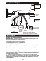
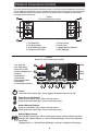
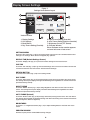
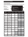
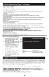
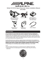
Perfect Fit 2010-Present Chevrolet Camaro Installation Manual KTX-CMO Camaro Dash Kit x 1 (Panel 7161/7162 (Preassembled Panel) Right Bracket x 1 (Panel 7164) Power Harness x 1 Left Bracket x 1 (Panel 7163) OnStar Module x 1 (KCX-OSMGM only) (Sold Separately) Antenna Adapter Introduction This KTX-CMO Perfect Fit installation kit is for 2010+ Chevrolet Camaro’s. Included are all the parts needed to install your Alpine INA-NAV-10, INA-NAV-20, INA-W900, INA-W900BT, or INA-W910 Audio Video Navigation system in a 2010+ Chevrolet Camaro. KTX-CMO Perfect Fit installation kit also includes an interface module that allows the Camaro’s steering wheel remote control of the Alpine system. Refer to the individual instruction sections of this manual to remove your vehicle’s factory radio and assemble the kit. Caution! Disconnect your vehicle’s negative battery terminal before the installation to help prevent electrical damage. We recommend the use of a digital multimeter to check vehicle wiring. Do not use a test light! A test light or grounded wire probe can cause damage to the vehicle’s computer and/or diagnostic systems. Avoid all factory airbag wiring. Airbags can accidentally deploy causing serious injury or even death. Notes: oØ2DDØXNTQØUDGHBKDlRØHMRSQTBSHNMRØENQØ@MXØRODBH@KØSNNKRØXNTQØHMRS@KK@SHNMØLHFGSØQDPTHQD oØ1D@CØ@KKØHMRSQTBSHNMRØ@BBNLO@MXHMFØXNTQØB@QØRSDQDNØENQØOQNODQØVHQHMFØ@MCØLNTMSHMFØ instructions 1 Factory Stereo Removal 1. Tum ignition to the ON position and shift vehicle into drive. NOTE: In order to complete Step 1 the baattery must be connected. After completing step 1, disconnect the negative battery cable and proceed to step 2. 2. Use a Panel-safe Removal Tool (PRT) to unclip Auxiliary gauge panel, unplug and remove. Ø4RDØ@ØRL@KKØÛ@SGD@CØRBQDVØCQHUDQØTMBKHOØRBQDVØB@OØKNB@SDCØNMØSGDØKNVDQØEQNMSØ@HCDØNEØSGDØRGHESØJMNA 4. Extract (1) T-20 Torx screw to remove gear shift knob. 5. Extract (4) 7mm screws securing shifter console, then with pick tool, unclip (1) clip located on each side under the shifter console, unplug and remove. 6. Use PRT to unclip each side panel from the center console. 7. Extract (1) Phillips head screw from each side located on the outer area of the center console. B. Extract (1) Phillips head screw from each side of center console’s rear panel, lift and pull back to remove. 9. Extract (3) Phillips head screws behind center console’s armrest. 10. Extract (1) Phillips head screw in front of beverage holder. 11. Use PRT to unclip 12V and USB/3.5mm housing inside the armrest, unplug and remove. 12. Use PRT to unclip center console and remove. 13. Extract (2) 7mm screws securing radio panel located under and to the rear of A/C controls. Use PRT to unclip radio fascia panel, unplug, and remove. 14. Extract (4) 7mm screws securing radio chassis/ Drive assembly, unplug, lift away and remove Stereo Assembly 1. Attach panels 7163 and 7164 to the Alpine head unit using the supplied screws (that come with the head unit). 2. Connect and mount the stereo in the dash. 3. Connect HVAC controls. Panel 7161/7162 mounts to the dash over the radio. Panel 7163 Panel 7164 Panel 7161/7162 Steering Wheel Controls Steering Wheel Control Operation WHENVEHICLEISEQUIPPED 1 1. Seek/Track Up (click SRC button upward) Ø BSHU@SDØ.M2S@Q Ø(EØDPTHOODC 3. De-activate OnStar®/ Mute Audio 4. Seek/Track Down (click SRC button downward) 5. SRC (Source) - Press in to change source 6. Volume Down 7. Volume Up "NMRTKSØUDGHBKDRØNQHFHM@KØNVMDQlRØL@MT@KØENQØ&,Ø.M2S@Q Ø instructions 2 2 7 SRC 6 3 4 5 Figure 6 Steering Wheel Control Layout Wiring Harness Diagram Yellow/Blue To Parking Brake (-) at the parking brake in drivers kick panel Yellow/Black To Foot Brake (+) at switch above pedal USB for interface ÚQLV@QDØTOC@SDØNMKX To Touch Screen Module in Kit AVN System To Bluetooth® Module Power Connector To Orange/White On Back Of Radio To Head Unit Power Connector 10A INA-W900 / INA-W900BT / INA-W910 / INA-NAV-10 / INA-NAV-20 7.5A To Steering Remote Input (Pigtail) To Chevrolet Camaro Vehicle Harness Blue/White To aftermarket @LOKHÚDQØQDLNSDØ turn on KCX-OSMGM for vehicles with OnStar® (Sold Separately) Non-Onstar KCE-250BT or (Bypass Plug) KCE-400BT Bluetooth® ,NCTKD Ø-NØBNMMDBSHNMØENQØ(- 6Ø ØØ!KTDSNNSG ØLNCTKDØNOSHNM@KØENQØ(- 6Ø KCE-250BT module included with the INA-W900BT. Vehicle Startup Connection And Initialization Procedure: IMPORTANT NOTE! The connection and startup process below must be followed, or the HVAC touch screen system may not operate properly. 1. Re-route factory HVAC connector to radio cavity. 2. Connect factory radio connector to Alpine harness. 3. Connect factory HVAC connector to Alpine harness. 4. IF USING OPTIONAL OnStar® MODULE: Remove looped 20 pin connector from Alpine G@QMDRRØ@MCØBNMMDBSØ.M2S@Q ØLNCTKD 5. Move OnStar® module, radio connector, and HVAC connector to the left of the radio cavity. Ø1NTSDØSGDØØ@MCØØOHMØBNMMDBSNQRØNEØ KOHMDØG@QMDRRØSNØNQHFHM@KØKNB@SHNMØNEØ'5 "ØBNMMDBtor. 7. Connect the Alpine harness along with antenna and all other accessories to the aftermarket radio and insert into radio cavity. Ø$MSDQØSGDØB@QØ@MCØRGTSØ@KKØCNNQRØ@MCØQDLNUDØSGDØJDX 9. Wait approximately 5 minutes for the vehicles computer to enter a sleep state (approx. 2 minutes after dome light turns off). ØØ8NTØL@XØMNVØBNMMDBSØSGDØØOHMØ@MCØØOHMØBNMMDBSNQRØSNØSGDØMDVØ'5 "ØBNMSQNKKDQ 11. While still in the vehicle with the doors shut, insert the key and start the vehicle’s engine. 3'$Ø.M2S@Q Ø,.#4+$Ø,423Ø!$Ø".--$"3$#Ø!$%.1$Ø3'$Ø-$6Ø'5 "Ø".-31.++$1Ø " -Ø!$Ø".--$"3$# 3 Climate & Convenience Controls The Touch Screen Interface replaces the factory climate, convenience and personalization controls built into the OEM Factory GM Radio system. This solution provides improved ergonomics while adding touch RBQDDMØB@O@AHKHSHDRØTMHPTDØSNØSGHRØRXRSDLØ1D@CØSGDØENKKNVHMFØRDBSHNMRØSNØE@LHKH@QHYDØXNTQRDKEØVHSGØSGDØ operating controls and settings. Figure 1 Control Panel Button Layout 1 5 2 6 3 7 SET 4 1. Fan Speed Up 2. Fan Speed Down 3. Air Conditioning On/Off 4. Climate Power On/Off 5. Power Unlock 6. Power Lock 7. Hazard Warning Flashers Ø2$3Ø2DSSHMFR Figure 2 Home TFT Color Touch Screen Layout 1. Air Temp Up 2. Air Temp Down 3. Max A/C On/Off 4. Driver’s Heated Seat 5. Defrost 6. Rear Defog 7. Recirculate Ø/@RRØ'D@SDCØ2D@S 9. Vent Mode 10. Fan Speed Indicator WARM 1 9 Temp Range 2 10 3 COOL 4 5 6 7 Power Press the Power button (Fig.1, #4) to toggle the climate controls On or Off. Power Door Lock Control Press the Lock button (Fig.1, #6) to lock both doors. Press the Unlock button (Fig.1, #5) to unlock both doors. Hazard Warning Flashers Press the Lock button (Fig.1, #6) to lock both doors. Press the Unlock button (Fig.1, #5) to unlock both doors. SET Settings Menu Access /QDRRØSGDØ2$3ØATSSNMØ%HFØØSNØ@BBDRRØSNTBGØRBQDDMØUDGHBKDØED@STQDRØ@MCØNSGDQØ settings. See “Display Screen” or “Vehicle Feature/Settings” sections for additional information. “Display Screen” or “Vehicle Feature/Settings” sections for additional information. 4 Climate & Convenience Controls (Continued) Fan Speed Control To increase fan speed, press the fan speed UP button on the control panel (pg. 4, Fig. 1, #1 ). On the color TFT touch screen a graphic level indicator will move up indicating the current fan speed (pg. 4, Fig. 2, #1 0). There are a total of 12 fan speed increments from completely off to maximum. To decrease fan speed, press the fan speed DOWN button on the control panel (pg. 4, Fig. 1, #2). On the color TFT touch screen a graphic level indicator will move down indicating the current fan speed (pg. 4, Fig. 2, #1 0). Continue pressing the DOWN button to turn fan completely off. Temperature Control Use the UP and DOWN arrows (pg. 4, Fig. 2, #1 & #2) on the color TFT touch screen to adjust vehicle air temperature. Touch the Red <Up> arrow to increase air temp. Touch the Blue <Down> arrow to decrease air temp. The temperature indicator will move up or down indicating the current temperature level. The temperature range is color-coded: Red indicates warmer air and Blue indicates cooler air. Air is directed Air is directed to Air Flow / Vent Control SNØSGDØÛNNQØUDMSØ the instrument Touch the vent control mode (pg. 4, outlets panel vent outlets Fig. 2, #9) on the color TFT touch Air will be screen to toggle through the current Air is directed to directed to the vent mode. Graphics are displayed the instrument windshield and according to the selected vent and panel vent outlets ÛNNQØ@MCNQØRHCDØ @HQÛNVØO@SSDQM @MCØSGDØÛNNQØUDMSØ vent outlets outlets Defog / Defrost Control Touch the Defog (pg. 4, Fig. 2, #5) on the Color TFT touch screen to turn Defog On or Off. 3GHRØBNMÚFTQ@SHNMØBKD@QRØVHMCNVRØNEØENFØNQØLNHRSTQDØ HQØVHKKØADØCHQDBSDCØSNØSGDØVHMCRGHDKCØ @MCØÛNNQØNTSKDSR Touch the Rear window defogger (pg. 4, Fig. 2, #6) on the Color TFT touch screen to turn the rear window defogger on or off. The rear window defogger turns off automatically 12 minutes. It can also be turned off by turning the ignition to ACC (ACCESSORY) or OFF position. If turned on again it runs for 6 minutes before turning off. At higher vehicle speeds, the rear defogger can stay on continuously. Note: For best results clear the windows of snow or ice before defrost settings. DO NOT OPERATE VEHICLE UNTIL WINDOWS ARE CLEAR! Air Conditioning To turn the air conditioning ON or OFF press A/C button on the control panel (pg. 4, Fig. 1, #3). A Blue indicator light turns on. If the fan is turned off or the outside temperature falls below freezing, the air conditioning will not work. The air conditioning might automatically come on when Defrost mode is selected. MAX Touch the MAX A/C button (pg. 4, Fig. 2, #3) on the color TFT touch screen to turn on Max A/C. Maximum cooling will occur with the temperature is adjusted to lowest cold setting and SGDØ%@MØRODDCØHRØRDSØ@SØL@WHLTLØ, 7Ø "ØHRØTRDCØSNØBNNKØSGDØB@QØCNVMØ@RØPTHBJKXØ@RØONRsible. Touch the Max A/C button again to return to the previous Fan speed and temp setting. Touch the Re-circulate button (pg. 4, Fig. 2, #7) on the color TFT touch screen to turn on QDBHQBTK@SHNMØ HQØVHKKØADØQDBHQBTK@SDCØHMRHCDØSGDØUDGHBKDØ3GHRØLNCDØGDKORØSNØPTHBJKXØBNNKØSGDØ air inside the vehicle or prevent outside air and odors from entering. Operating recirculation mode while the A/C is off increases humidity and may cause the windows to fog. Recirculation is not available in the Defrost or Defog modes. Heated Seats Touch the driver’s seat heater (pg. 4, Fig. 2, #4) button on the color TFT touch screen to turn on the driver’s seat heater. The engine must be running to use heated seats. A Button graphic will show the level of heat selected: Two lights = high or one light = low). Press the button repeatedly to cycle through the temperature settings or to turn the heated seat OFF. Touch the O@RRDMFDQlRØRD@SØGD@SDQØOFØØ%HFØØØATSSNMØNMØSGDØBNKNQØ3%3ØSNTBGØRBQDDMØSNØSTQMØNMØSGD Passenger’s seat heater. The engine must be running to use heated seats. A button graphic will show the level of heat selected: Two lights = high or one light = low). Press the button repeatedly to cycle through the temperature settings or to turn the heated seat OFF. 5 Display Screen Settings Figure 3 Settings Home Screen Layout DISPLAY 1 CAR 2 3 - Brightness io: 48 sw:68 DAY NIGHT + 7 AUTO Version Number 4 5 1. Display Settings 2. Car Settings 3. Back/Return 4. Day Theme Setting (Override) 6 5. Night Theme Setting (Override) 6. Auto Theme Setting (Vehicle-controlled) 7. Brightness Control (TFT Screen) Ø.UDQUHDVØ6HMCNV Other: Software version number appears on lower left corner of set screen 3%44).'3-%.5 /QDRRØSGDØm2DSnØATSSNMØ%HFØØØNMØSGDØBNMSQNKØO@MDKØSNØ@BBDRRØSGDØTRDQØBNMSQNKKDCØED@STQDRØ@MCØ settings. The “Settings” Home Screen will appear (Fig. 3) above. $)30,!94!"$EFAULT3ETTINGS3CREEN Touch the “Display” Tab (Fig. 3, #1) to access various settings for the Touch Screen. CAR TAB Touch the “Car” Tab (Fig. 3, #2) to go the second settings menu for access to vehicle comfort and convenience features. See next section “Vehicle Feature Settings”. 2%452."544/. Touch the return button (Fig. 3, #3) to exit settings mode. DAY THEME Touch the “DAY” button (Fig. 3, #4) to assign Daytime color theme for the Color TFT touch screen. This setting will keep the display with light colored background regardless of outside environment (overrides Factory control). NIGHT THEME Touch the “NIGHT” button (Fig. 3, #5) to assign Nighttime color theme for the Color TFT touch screen. This setting will keep the display with dark colored background regardless of outside environment (overrides Factory control). !54/4(%-%$EFAULT Touch the “AUTO” button (Fig. 3, #6) to assign Automatic (Factory) control of the TFT color theme. This setting will keep Data-controlled switching color theme according to the outside environment. (Light for Daytime / Dark for Nighttime). BRIGHTNESS Touch the”+”/”-” Brightness buttons (Fig. 3, #7) to adjust the Brightness of the Color TFT touch screen. PREVIEW WINDOW /QNUHCDRØ@ØPTHBJØOQDUHDVØNEØ# 8-(&'3ØRDSSHMFØBG@MFDR 6 Vehicle Feature Settings Tile color TFT touch screen interface is used to access the vehicle’s built-in customization features. 6%()#,%3%44).'3-%.5 /QDRRØSGDØm2DSnØATSSNMØRDDØO@FDØØ%HFØØØNMØSGDØBNMSQNKØO@MDKØSNØ@BBDRRØSGDØTRDQØBNMSQNKKDCØED@STQDRØ @MCØRDSSHMFRØKGDØm2DSSHMFRoØ'NLDØ2BQDDMØVHKKØ@OOD@QØRDDØO@FDØØ%HFØØoØ/QDRRØSGDØ" 1ØATSSNMØRDDØO@FDØ 6, Fig. 3, #2) to access the vehicle features list as shown in Fig. 4 (below). Figure 4 Vehicle Settings Home Screen Layout 1. Back Button 2. Vehicle Feature List 3. Select/Next Button 4. Scroll Down Button 1 < 2 Climate and Air Quality Collision Detection Systems Lighting Power Door Locks Remote Lock, Unlock, Start Feature Title Description Setting 1 Setting 2 Climate and Air Quality Heated Seats When Remote Starting On Off Collision/ Detection Systems Park Assist: Ultrasonic Object Sensors On Off Lighting Vehicle Locator On Off Lighting Cont. Exit Lighting Off 30 Seconds Power Door Locks Anti-Lockout On Off Power Door Locks Cont. Auto Door Lock/ Unlock On Off Power Door Locks Cont. Delayed Door Lock On Off Remote Lock/ Unlock/Start Unlock Feedback (Lights) On Off Remote Lock/ Unlock/Start Cont. Lock Feedback (Lights, Horn) Lights Lights + Horn Chirp Remote Lock/ Unlock/Start Cont. Door Unlock Driver’s Door First All Doors Aftermarket Radio Type Sets Steering Wheel Controls Select: Alpine, Clarion, JVC, Kenwood, Pioneer, Or Sony Return To Factory Default Restore Settings Yes No 7 > > > > > 3 4 Setting 3 Setting 4 1 Minute 2 Minutes Horn Chirp Only Off Vehicle Feature Settings Continued Vehicle Feature Details p#LIMATE!ND!IR1UALITY Heated Seats: On or Off when vehicle is remote started p#OLLISION$ETECTION3YSTEMS Park Assist features: Enable or Disable the vehicle’s ultrasonic bumper object sensors (Depends on UDGHBKDØNOSHNMRDPTHOLDMS p,IGHTING Exit Lighting: Set exterior lights delay when exiting vehicle at night Vehicle Locator Lights: Set exterior lights ON or OFF when unlocking/approaching at night p0OWER$OOR,OCKS Unlocked Door Anti Lockout: Prevents vehicle locking if Driver door is open (Helps to prevent keys from being locked inside). Auto Door Unlock: Vehicle unlocks when Shifted into Park (Auto trans) or when Key is removed (Manual Trans) Delayed Door Lock: Delays door locking p2EMOTE,OCK5NLOCK3TART Unlock Feedback (Lights): Enable or Disable vehicle’s light Flash when Unlocking vehicle with Remote Locking Feedback: Select the type of audible/visual Lock indicator when Locking vehicle with the Remote - Lights Flash, Lights and Horn blip, or Horn blip only #NNQØ4MKNBJØ.OSHNMRØ2DKDBS@AKDØTMKNBJHMFØVGDMØTRHMFØQDLNSDØ#QHUDQlRØCNNQØÚQRSØNQØ!NSGØCNNQRØ@SØNMBD Remote Vehicle Starting: Enable or Disable Remote Vehicle Starting p!FTERMARKET2ADIO4YPE3TEERING7HEEL#ONTROL/UTPUT 2DKDBSØSXODØNEØ ESDQL@QJDSØ1@CHNØENQØRSDDQHMFØVGDDKØHMSDQE@BDØBNMÚFTQ@SHNMØ/HNMDDQØ2NMXØ KOHMD Kenwood, Clarion, JVC) p2ETURNTO&ACTORY3ETTINGS Restores all customized settings to Factory default: Yes or No How To Change Feature Settings 1. 2. 3. 4. 5. Press the “SET” button to access SGDØ"NMÚFTQ@SHNM2DSSHMFRØ,DMTØ (see page 4, Fig. 1, #B) Touch the “CAR” button on the TFT RBQDDMØO@FDØØ%HFØØØSNØAQHMFØ up the car Feature list. Touch the name of the Feature you would like to access/change the settings (page 7, Fig. 4 #2). Note: you may need to scroll down to view all options. Touch the option valUe you wish to change and the selected value will turn to GREEN or RED color text. Touch the Back button (Fig. 5, f1, above) to go back one level or view other features. Climate and Air Quality 1 < 2 Remote Start Auto Heated Seats Figure 5 1. Back Button Vehicle Feature Screen 2. Vehicle Feature Value Layout 3. Selected Vehicle Feature Liability Disclaimer #TDØSNØBG@MFDRØHMØCDRHFMØ@MCØL@MTE@BSTQHMFØSG@SØL@XØNBBTQØVHSGØXNTQØRODBHÚBØUDGHBKDØHSØHRØHLONQS@MSØSG@SØ you do not rely solely on vehicle information contained in this installation manual, such as dash disassemAKXØVHQDØG@QMDRRØ@MCØBNCDRØ2TBGØHMENQL@SHNMØRGNTKCØADØBNMÚQLDCØVHSGØSGDØUDGHBKDØL@MTE@BSTQDQØ KOHMDØ $KDBSQNMHBRØ(MBØ@MCØHSRØ@EÚKH@SDCØBNLO@MHDRØHRØMNSØQDRONMRHAKDØENQØC@L@FDØSG@SØL@XØNBBTQØSNØXNTØNQØXNTQØ automobile during the installation of the Perfect Fit Kit. (EØXNTØG@UDØ@MXØETQSGDQØPTDRSHNMRØEDDKØEQDDØSNØBNMS@BSØ KOHMDØ3DBGØ2TOONQSØ@SØ- 5'$+/ ALPINE ELECTRONICS OF AMERICA, INC., 19145 Gramercy Place, Torrance, CA 90501, U.S.A ALPINE ELECTRONICS OF CANADA, INC., 777 Supertest Road, Toronto, Ontario M3J 2M9, Canada Do not send products to these addresses. Call the toll free number or visit the website to locate a service center. 8 3