1
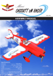
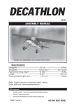
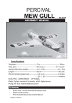
WWW.SEAGULLMODELS.COM
ASSEMBLY MANUAL
ANGEL
2000 glider
“ Graphics and specifications may change without notice “ .
MS: 129
Specifications:
ARF
Wingspan---------------78.7 in ( 200cm).
Wing area---------------582.8sq.in ( 37.6sq.dm).
Weight-------------------2.4lbs ( 1.1 kg).
Length-------------------45.1 in ( 114.6cm).
Motor-------------------15 brushless outrunner motor.
Radio--------------------4 channel with 2 servos.
Electric conversion: Optional.
www.seagullmodels.com
1
Instruction Manual.
Angel 2000 Glider
INTRODUCTION.
Thank you for choosing the ANGEL 2000 GLIDER ARTF by SEAGULL MODELS
COMPANY LTD,. The ANGEL 2000 GLIDER was designed with the intermediate/advanced sport flyer in mind. It is a semi scale airplane which is easy to fly and quick to assemble. The airframe is onventionally built using balsa, plywood to make it stronger
than the average ARTF, yet the design allows the aeroplane to be kept light. You will find
that most of the work has been done for you already. The motor mount has been fitted and the hinges are pre-installed. Flying the ANGEL 2000 GLIDER is simply a joy.
This instruction manual is designed to help you build a great flying earoplane. Please read
this manual throughly before starting assembly of your ANGEL 2000 GLIDER . User the
parts listing below to indentify all parts.
WARNING.
Please be awere that this aeroplane is not a toy and if assemble or used incorrectly it is
capable of causing injury to people or property. WHEN YOU FLY THIS AEROPLANE YOU
ASSUME ALL RISK & REPONSIBILITY.
If you are inexperienced with basic RC flight we strongly recommend you contact your RC
supplier and join your local RC model Flying Club. RC Model Flying Clubs offer a variety of
training procedures designed to help the new pilot on his way to successful RC flight. They
will also be able to advise on any insurance and safety regulations that may apply.
KIT CONTENTS
3
3
1
2
2
2
WWW.SEAGULLMODELS.COM
KIT CONTENTS.
SEA12901Fuselage
SEA12902 Wing set
SEA12903 Tail set
HINGING THE RUDDER.
Note : The control surfaces, including the ailerons, elevators, and rudder, are prehinged with
hinges installed, but the hinges are not glued in
place. It is imperative that you properly adhere
the hinges in place per the steps that follow using a high-quality thin C/A glue.
Hinge.
Epoxy.
ADDITIONAL ITEMS REQUIRED.
15 brushless outrunner motor.
Radio 4 chanel with 2 servos.
TOOLS & SUPPLIES NEEDED.
Thick cyanoacrylate glue.
30 minute epoxy.
5 minute epoxy.
Hand or electric drill.
Assorted drill bits.
Modelling knife.
Straight edge ruler.
2mm ball driver.
Phillips head screwdriver.
220 grit sandpaper.
90° square or builder’s triangle.
Wire cutters.
Masking tape & T-pins.
Thread-lock.
Paper towels.
Epoxy.
3
Instruction Manual.
Angel 2000 Glider
HINGING THE ELEVATORS.
Glue the elevator hinges in place using
the same techniques used to hinge the
rudder.
INSTALLING THE HORIZONTAL
STABILIZER.
1) Using a ruler and a pen, locate the centerline of the horizontal stabilizer, at the trailing
edge, and place a mark. Use a triangle and
extend this mark, from back to front, across
the top of the stabilizer. Also extend this
mark down the back of the trailing edge of
the stabilizer.
3) Slide the stabilizer into place in the precut
slot in the rear of the fuselage. The stabilizer
should be pushed firmly against the front of
the slot.
4) With the stabilizer held firmly in place,
use a pen and draw lines onto the stabilizer
where it and the fuselage sides meet. Do this
on both the right and left sides and top and
bottom of the stabilizer.
Pen.
Draw center line.
2) Using a modeling knife, carefully remove
the covering at mounting slot of horizontal
stabilizer ( both side of fuselage).
Cut.
4
5) Remove the stabilizer. Using the lines you
just drew as a guide, carefully remove the
covering from between them using a modeling knife.
Remove covering.
WWW.SEAGULLMODELS.COM
When cutting through the covering to
remove it, cut with only enough pressure to
only cut through the covering itself. Cutting
into the balsa structure may weaken it.
6) Using a modeling knife, carefully remove
the covering that overlaps the stabilizer
mounting platform sides in the fuselage. Remove the covering from both the top and the
bottom of the platform sides.
8) Next assemble and install the elevator
control horn.
Start each screw partway into the holes
in the control horn, as shown. Thread the
screws in until the tip of each screw protrudes just slightly from the bottom of the
horn base.
7) When you are sure that everything is
aligned correctly, mix up a generous amount
of 30-minute epoxy. Apply a thin layer to the
top and bottom of the stabilizer mounting
area and to the stabilizer mounting platform
sides in the fuselage. Slide the stabilizer in
place and realign. Double check all of your
measurements once more before the epoxy
cures. Hold the stabilizer in place with T-pins
or masking tape and remove any excess epoxy
using a paper towel and rubbing alcohol.
Remove covering.
Epoxy.
Then hold the control horn clamping plate
in place while you finish threading the
screws all the way in. When done, you can
file or grind off the protruding sharp point
of the screws if you desire.
Epoxy.
5
Instruction Manual.
Angel 2000 Glider
2) Using a modeling knife, remove the covering from over the precut hinge slot cut into
the lower rear portion of the fuselage.
2x15mm
Remove covering.
INSTALLING VERTICAL STABILIZER.
3) Next assemble and install the rudder control horn as the process for elevator control
horn.
1) While holding the vertical stabilizer firmly in place, use a pen and draw a line on each
side of the vertical stabilizer where it meets
the top of the fuselage.
Epoxy.
When cutting through the covering to remove it, cut with only enough pressure to only
cut through the covering itself. Cutting into
the balsa structure may weaken it.
4) Slide the vertical stabilizer back inplace. Using a triangle, check to ensure
that the vertical stabilizer is aligned 90º
to the horizontal stabilizer.
6
WWW.SEAGULLMODELS.COM
INSTALLING THE FUSELAGE SERVOS.
Horizontal
Stabilizer.
90º
Vertical
Stabilizer.
Because the size of servos differ, you
may need to adjust the size of the precut .
opening in the mount. The notch in the
sides of the mount allow the servo lead to
pass through.
1) Install the rubber grommets and brass
collets onto the fuselage servo. Test fit the
servo into the aileron servo mount.
2) Secure the servos with the screws provided with your radio system.
6) When you are sure that everything is
aligned correctly, mix a generous amount
of 30-minute epoxy. Apply a thin layer
to the mouting slot and to bottom of the
vertical stabilizer mounting area. Apply
epoxy to the bottom and top edges of the
filler block and to the lower hinge also. Set
the stabilizer in place and realign. Double check all of your measurments once
more before the epoxy cures. Hold the
stabilizer in place with T-pins or masking
tape and remove any excess epxy using a
paper towel and rubbing alcohol. Allow
the epoxy to fully cure before proceeding.
Rudder.
Elevator.
SERVO ARM INSTALLATION.
Install adjustable servo connector in the
servo arm as same as picture below:
Rudder.
Elevator.
7
Instruction Manual.
Angel 2000 Glider
ELEVATOR - RUDDER PUSHROD
HORN INSTALLATION.
Nylon Snap keeper.
1) Install the elevator control horn using
the same method as with the aileron control horns.
2) Position the elevator control horn on
the both side of elevator.
M2 clevis.
M2 lock nut.
8mm
Elevator pushrod.
Control horn
Elevator pushrod.
Control horn
Fuel tubing.
8mm
Hex Nut.
Rudder pushrod.
8
M2 clevis.
WWW.SEAGULLMODELS.COM
WING ASSEMBLY.
Remove covering.
ELECTRIC POWER CONVERSION.
Locate the items neccessary to install the
electric power conversion included with
your model.
9
Angel 2000 Glider
Instruction Manual.
2x8 mm
INSTALLING THE SPINNER.
Install the spinner backplate, propeller
and spinner cone.
The propeller should not touch any
part of the spinner cone. If it does, use a
sharp modeling knife and carefully trim
away the spinner cone where the propeller comes in contact with it.
10
WWW.SEAGULLMODELS.COM
ATTACHMENT WING- FUSELAGE.
INSTALLING THE BATTERY RECEIVER.
1) Plug the five servo leads and the switch
lead into the receiver. Plug the battery pack
lead into the switch also.
2) Wrap the receiver and battery pack in the
protective foam rubber to protect them from
vibration.
3) Route the antenna in the antenna tube inside the fuselage and secure it to the bottom
of fuselage using a plastic tape.
Wing bolt.
ATTACHMENT HATCH COVER ON
THE FUSELAGE.
Cut
11
Angel 2000 Glider
Instruction Manual.
BALANCING.
1) It is critical that your airplane be
balanced correctly. Improper balance will
cause your plane to lose control and
crash. THE CENTER OF GRAVITY IS LOCATED 86MM BACK
FROM THE LEADING EDGE OF
THE WING AT THE WING ROOT.
2) Mount the wing to the fuselage. Using
a couple of pieces of masking tape, place
them on the bottom side of the wing
86mm back from the leading edge of the
wing at the wing root.
3) It should hang level when suspended
at the recommended balance point. Place
your fingers on the masking tape and
Accurately mark the balance point on
the botttom of the wing on both sides of
the fuselage. The balance point is located
86mm back from the leading edge of the
wing at the wing root. This is the balance point at which your model should
balance for your first flights. Later, you
may wish to experiment by shifting the
balance up to 10mm forward or back to
change the flying characteristics.
Epoxy.
12
WWW.SEAGULLMODELS.COM
Moving the balance aft makes the model
more agile with a lighter and snappier
”feel”. In any case,please start at the location we recommend .
86 mm
With the wing attached to the fuselage,
all parts of the model installed ( ready to
fly), and empty fuel tanks, hold the model at the marked balance point with the
stabilizer level.
Lift the model. If the tail drops when
you lift, the model is “tail heavy” and you
must add weight* to the nose. If the nose
drops, it is “nose heavy” and you must
add weight* to the tail to balance.
*If possible, first attempt to balance the
model by changing the position of the receiver battery and receiver. If you are unable to obtain good balance by doing so,
then it will be necessary to add weight to
the nose or tail to achieve the
proper balance point.
CONTROL THROWS.
Elevator:
Up :
Down :
15 mm
15 mm
Rudder:
Right :
Left :
20 mm
20 mm
13
Angel 2000 Glider
FLIGHT PREPARATION.
Check the operation and direction
of the elevator, rudder, ailerons and
throttle.
A) Plug in your radio system per the
manufacturer’s instructions and turn
everything on.
B) Check the elevator first. Pull
back on the elevator stick. The elevator halves should move up. If it they do
not, flip the servo reversing switch on
your transmitter to change the direcC) Check the rudder. Looking from
behind the airplane, move the rudder
stick to the right. The rudder should
move to the right. If it does not, flip
the servo reversing switch on your
transmitter to change the direction.
Instruction Manual.
PREFLIGHT CHECK.
1) Completely charge your transmitter and receiver batteries before
your first day of flying.
2) Check every bolt and every glue
joint in the ANGEL 2000 GLIDER
to ensure that everything is tight and
well bonded.
3) Double check the balance of the
airplane. Do this with the fuel tank
empty.
4) Check the control surfaces. All
should move in the correct direction
and not bind in any way.
5) If your radio transmitter is
equipped with dual rate switches double check that they are on the low rate
setting for your first few flights.
6) Check to ensure the control surfaces are moving the proper amount
for both low and high rate settings.
7) Check the receiver antenna. It
should be fully extended and not
coiled up inside the fuselage.
8) Properly balance the propeller.
An out of balance propeller will cause
excessive vibration which could lead
to engine and/or airframe failure.
We wish you many safe and enjoyable flights
with your ANGEL 2000 GLIDER.
14
14