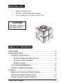
1
AURORA SERIES
PORTABLE RADIO
User’s Manual
Aurora User’s Manual
1
2
BK Radio
PACKING LIST
1 – Radio with Belt Clip
1 – Flexible, Helical-Wound Antenna
1 – User’s Manual (P/N 7001-30927-401)
CAUTION
Do NOT operate a
damaged radio.
!
ra
o
r
Au
TABLE OF CONTENTS
WELCOME ......................................................................8
INTRODUCTION .............................................................9
Optional Accessories .................................................9
External Speaker/Microphone ..............................9
External VOX Headset .........................................9
Battery Packs .......................................................9
FCC REQUIREMENTS ............................................10
SAFETY PRECAUTIONS ........................................10
Features ........................................................................ 11
Basic and Advanced Model Radios ......................... 11
Advanced Model Radios Only ................................. 11
Dealer Programmable Options ................................12
Aurora User’s Manual
3
TABLE OF CONTENTS
Before Using Your Radio ...............................................13
Battery Installation and Removal .............................13
Antenna Installation and Removal ...........................14
Radio Views ..................................................................15
Aurora Radio Controls ..................................................16
Front View ................................................................16
Display ................................................................16
Backlight .............................................................17
Keypad ...............................................................17
Speaker ..............................................................17
Top View ..................................................................18
Status Indicator ..................................................18
On/Off Volume Knob ...........................................18
Squelch Knob .....................................................18
Programmable Three-Position Switch ................20
Emergency Button ..............................................20
Channel Selector Knob ......................................20
Side Views ...............................................................21
PTT Switch .........................................................21
Programmable Softkey Buttons ..........................21
Options Connector .............................................22
Basic Operation.............................................................23
Receive ....................................................................23
TRANSMIT ...............................................................24
Code Guard Operation ..................................................25
Code Guard Receive ...............................................25
Code Guard Transmit ..............................................26
4
BK Radio
TABLE OF CONTENTS
Built-in Features ............................................................27
Audio ........................................................................27
Audio Options ..........................................................28
Battery-Saver Feature .............................................29
VOX Operation ........................................................29
Channel Selector .....................................................30
HI/LOW Transmit Power ..........................................31
Function Menu .........................................................32
Mode Selections .................................................32
Backlite ...............................................................33
Selecting and Activating Frequently Called
“Phone List” Numbers.........................................34
Editing Frequently Called Numbers ...................35
DTMF Encoding .......................................................36
ANI Encoding ...........................................................36
Transmit Time-Out Timer .........................................37
Talk Around ..............................................................37
Man-Down Switch ....................................................37
Emergency Group/Channel .....................................38
Activation .................................................................38
Enabling/Disabling ...................................................39
Transmit Speed and Frequency...............................39
Operating Modes ...........................................................40
Manual Mode ...........................................................40
Tone/Monitor Toggle ...........................................41
Code Guard Mode ..............................................42
Variable Guard ...................................................43
Aurora User’s Manual
5
TABLE OF CONTENTS
Scan Operation .......................................................43
Talkback Scan ....................................................43
Scan All Groups .................................................44
Change the Scan List .........................................44
Scanning Options ...............................................44
Scan Delay .........................................................44
Talk Around ........................................................45
Scan in Tone Mode .............................................46
Scan in Monitor Mode ........................................46
Transmit on Priority Channel ..............................46
Channel Scan Delete/Add ..................................47
Priority Scan .......................................................48
Priority Scan with Code Guard ...........................48
Priority Modes ..........................................................48
Priority Delay ......................................................50
Priority Receiving ...............................................50
Priority During Scan-All-Groups Scanning .........50
Receive Mode ..........................................................51
Groups ................................................................51
Display Modes .........................................................52
Tuning Range ..........................................................52
Frequency Display Mode .........................................53
Alpha Display Mode .................................................54
Channel Display Mode.............................................55
Radio Paging Code .......................................................56
Selective Calling ......................................................56
Receiving a Call .......................................................56
Sending a Call .........................................................57
Radio Check ............................................................57
DTMF Dialing ..........................................................58
6
BK Radio
TABLE OF CONTENTS
Originating a Call .....................................................58
Frequently Called Numbers and Call Paging .....59
Radio Paging ......................................................61
Flex Mode ................................................................61
Keypad and Channel Selector Lock ........................61
Busy Channel Lockout ..................................................62
Battery Power ................................................................63
Battery Saver ...........................................................63
Radio Power-Up ......................................................65
Error Messages .............................................................65
Stun ...............................................................................65
Aurora Programmed Switch Settings ............................67
Troubleshooting Guide ..................................................69
Maintenance ..................................................................70
Service .....................................................................70
Specifications ................................................................71
Definitions and Acronyms .............................................73
Aurora User’s Manual
7
WELCOME
Statistics show that about 80 percent of you will
not look at this manual until after you’ve already
taken the radio out of the box, tried to assemble it,
played around with it, and at some point came up
with something you didn’t understand.
IMPORTANT
So much
for this
box over
here.
To prevent
possible
damage, read all
instructions
before operating
this radio.
Even if you are reading this before operating
your radio, you’re still not planning on
reading all the instructions before you try to
work with your radio, are you?
Well, just be careful
because as our warranty
states, BK Radio isn’t
going to cover defects
caused by:
• Physical abuse or
misuse of the radio
• Neglect or accident
• Improper use or
installation of the radio
• Repair or alteration by
unauthorized personnel
8
BK Radio
INTRODUCTION
Congratulations, you now own a BK Radio Aurora Series
Flex•Mode™ Radio! This synthesized portable radio uses a
microprocessor core to give you features and performance
previously unavailable in a hand-held two-way radio. The
Aurora radio has been designed to meet the tough
requirements of today’s communications environment.
The Aurora Series Radios include two models:
• A basic radio model with 1 group of up to 16
channels without keypad or display
• An advanced radio model with 1–15 groups of up to
16 channels each with a keypad and display
These Aurora radios all offer VHF frequency band units.
OPTIONAL ACCESSORIES
External Speaker/Microphone
The Aurora radio has optional external speaker/microphones
(LAA0208 and LAA 0222). When the speaker/microphone
is installed with the options connector, the internal speaker is
defeated.
External VOX Headset
Another option for the Aurora radio is an external VOX
headset. When the headset is installed via the options
connector, the internal speaker/microphone is defeated.
Battery Packs
The following battery packs are available:
•
•
•
•
LAA 0183
LAA 0163
LAA 0167
LAA 0118
Aurora User’s Manual
NiCd, AA, 1200 mAh
NiMH, AA, 1450 mAh
NiMH, 4/5A, 1800 mAh
Shell for alkaline disposable
9
Battery Charger
The optional battery charger (LAA 0337) has a dual well. One
well is fast-charge, and the other is trickle-charge.
Carry Case
To give your radio more protection, you can order the optional
carry case (LAA 0437).
FCC REQUIREMENTS
Your radio must be properly licensed by the Federal
Communications Commission prior to use. Your BK Radio
dealer can assist you in meeting these requirements. Your
dealer will program each radio with your authorized
frequencies, signaling codes, etc., and will be there to meet
your communications needs as your system expands.
SAFETY PRECAUTIONS
• Do not operate the transmitter in close
proximity to blasting caps.
• Do not operate the radio in an explosive
atmosphere (petroleum fuels, solvents,
dust, etc.) unless your radio is an
intrinsically safe model designed for such
use.
10
BK Radio
FEATURES
All Aurora radios have features that are programmed into
both the basic and the advanced models, except for scanning
features, which are only available in the advanced model.
Below is a list of features that are standard to all Aurora
radio models, as well as those features that must be
programmed by your dealer.
BASIC AND ADVANCED MODEL RADIOS
•
Busy Channel Lockout
•
Code Guard™ (CTCSS/CDCSS) on any/all channels
•
Transmit Timeout Timer (per channel group)
•
Priority Channel Operation
•
Hi/Lo Transmit Power
•
Soft-key and soft-switch programming
•
Emergency switch
ADVANCED MODEL RADIOS ONLY
•
Code Guard user reassignment
•
Channel, frequency, or alpha user-changeable display
modes
•
Priority scan
•
Multiple scan
•
Talkback scan
•
DTMF number dialing (keypad)
•
Alphanumeric display
Code Guard™ is a trademark of BK Radio.
Aurora User’s Manual
11
DEALER PROGRAMMABLE OPTIONS
12
•
Five-tone ANI encode/decode
•
Two-tone sequential decode
•
Radio Paging: ANI (two-tone, five-tone, DTMF)
with frequently called number memory
•
VOX (Voice-Operated Transmissions)
•
Internal options board activation
•
Keyless front panel radio parameter programming
•
Man Down (requires optional factory-installed tilt
switch)
•
Radio stun feature
BK Radio
BEFORE USING YOUR RADIO
BATTERY INSTALLATION AND REMOVAL
Installing the Battery
The battery for the Aurora radio is connected on the back side
of the radio. To install the battery, follow the steps below:
1. With the radio in one
hand and the battery in
the other hand, face the
backside of the radio and
the inner side of the
battery toward each
other.
Side View
Bottom
Tabs
Locking Tabs
Rear View
2. Align the bottom tabs on
the battery with the
indents on the bottom of
the radio and press the
radio and battery together
at a 45° angle.
3. While keeping the bottom
of the battery and radio
together, snap the top of
the battery to the top of
the radio. The locking
tabs will hold the battery
in place.
Figure 1. Installing and removing the battery
Aurora User’s Manual
13
Removing the Battery
WARNING:
Explosion Hazard
Do not dispose a battery pack into a fire.
To avoid explosion, intrinsically safe radios designed
for use in hazardous environments MUST use
replacement batteries approved by Factory Mutual.
To remove the battery, press down on the locking tabs and
reverse the order for installing the battery.
Antenna Installation and Removal
Before using your Aurora
radio, you need to install the
antenna.
• To install the antenna,
carefully place it on the
TNC-type antenna
connector located on the
right side of the radio.
Turn the antenna
clockwise until it is firmly
attached.
• To remove the antenna,
turn the antenna
counterclockwise until
you can lift the antenna
away from the radio.
Figure 2. Installing and removing the antenna
14
BK Radio
RADIO VIEWS
Speaker
Battery
Battery
Tab
Aurora
Microphone
LED
Display
Belt
Clip
Keypad
Battery
Recharge
Terminals
Figure 3. Front and back view
Aurora User’s Manual
15
AURORA RADIO CONTROLS
FRONT VIEW
Display
The Aurora advanced model radios have a front panel display that
consists of status icons and an alphanumeric display of channel
information and radio status. If you select the alpha display mode,
the display will show the preprogrammed alphanumeric channel
identifier. If you switch to channel or frequency display modes, the
LCD displays either the channel number or the channel frequency
information. In all cases, the radio status indicators (icons) are
shown.
Table 1. Status Icons
Icon
Status
Low Battery
Mandown / Emergency
VOX enabled
Tone mode activated
Hi/Lo Transmit Power indication
Hi power
Lo power
Radio Paging Code (audible code) assigned
Keyboard Locked indicator
Transmitter Keyed Up (mimics the transmit
status indicator except it functions even in
military mode)
16
BK Radio
FRONT VIEW (continued)
Backlight
The Aurora radio display can be backlit, and your dealer
programmed one of the following options for your radio:
1. Backlight on whenever you press a key (1–6-second auto
timeout)
2. Backlight on whenever a signal is received and the audio is
sent to the speaker (1–6-second auto timeout starting at
carrier drop)
3. Backlight on whenever you press a key or a signal is
received and the audio is sent to the speaker (0–6-second
auto timeout starting at key press or carrier drop)
4. No backlight (military/strategic applications). This option also
prevents the Transmit/Busy/Low Battery LED to light up.
Note: If Option 4 of the display backlight LED feature is
programmed, the multicolored status LED will not light
under any condition.
Keypad
The Aurora radio advanced models have a keypad that contains the
keys necessary to access a channel group directly, generate DTMF
tones and paging codes, and change operating modes. The keypad
is backlit and controlled by the same backlight control as the
display.
Speaker
The Aurora radio has an internal speaker so you can listen to the
audio received from active carriers on tuned receive-channel
frequencies. The internal speaker also lets you hear any audible
notifications.
Microphone
The Aurora radio has an internal microphone so you can transmit
audio on active carriers with tuned transmit channel frequencies.
Aurora User’s Manual
17
TOP VIEW
Status Indicator
A dual color LED indicates the transmit mode, active receive
carrier, priority sampling, low battery, cloning, and radio error
conditions in the Aurora radio.
Table 2. Status Indicator Colors
Color
Steady
Red
Steady
Green
Flashing
Orange
10-second
Blinking Red
Steady
Orange
5-Second
Steady Orange
Indication
The radio is transmitting
The receive channel is busy (carrier detected)
or squelch is open
The radio is sampling for the priority channel
The battery is low
Radios are transferring data during cloning
Error—Number is shown in the display of
advanced radios and then the radio is reset
For example, if the radio receive channel is busy and the battery is
low, the status indicator will be green with momentary red flashes
every 10 seconds.
On/Off Volume Knob
Use the On/Off Volume knob to turn the radio on and off, and
control the volume of the unmuted internal and external speaker.
Squelch Knob
The squelch control is used to eliminate speaker noise when a
receive signal is not present and no receive Code Guard is being
used for the receiving frequency.
18
BK Radio
TOP VIEW
On/Off
Volume
Squelch
Antenna
Connector
Channel
Selector
3-Position
Toggle Switch*
Status
LED
Scan Mode**
*Three-Position Toggle Switch
(Factory Default)
1 Channel frequency
2 Channel label
3 Group number, channel
number, and bandwidth
**Programmable Red Switch
Factory Default
— Scan
Programmable to — Emergency
Figure 4. Top view
Aurora User’s Manual
19
Programmable Three-Position Switch
The three-position switch on top of the radio is programmed by the
dealer for features you can select in a variety of configurations.
The default configuration is shown in Table 3 below:
Table 3. Factory Default for Three-Position Switch
Position
1
2
3
Features
Channel frequency
Channel label
Group number, channel number, and
bandwidth mode
Emergency Button
The red button on the top of the radio can be programmed by the
dealer as an emergency switch to transmit an emergency ANI
sequence when pressed. The factory default for the red button,
however, is scan mode.
Channel Selector Knob
The Aurora radio has a channel selector knob on the top of the
radio that lets you determine the channel to tune to when receiving
and transmitting in manual mode.
General channel parameters include:
• Busy Channel Lockout
• Scan list assignment
• Hi/Lo transmit power specification
• Channel type (voice or data)
• Alpha display information for each channel
Channel parameters of the Aurora radio include:
• Transmit and receive frequencies
• Code Guard assignment, which is received with each
frequency
• ANI system and ANI code type
• bandwidth, whether narrow or wide
20
BK Radio
SIDE VIEWS
Programmable
Switches
PTT Switch
Use the PTT Switch to key-up the radio’s
transmitter. At times, activating the PTT
switch will not allow transmitter operation,
such as when channels have active carriers
with busy channel lockout is programmed or
if no transmit frequency was programmed for
the displayed channel.
Programmable Softkey Buttons
PTT
The three softkey buttons on the side of the
radio are programmed by your dealer to give
you the radio features you want. The default
configuration for the three softkey buttons is
shown in the table below:
Table 4. Programmable Softkey Buttons
Button
Top
Feature
Toggles Code Guard on and off
Middle Toggles priority mode on and off
Bottom Toggles high and low power
Figure 5. Left side view
Aurora User’s Manual
21
Options Connector
The Aurora radio has a sealed options
connector on the side of the radio
(opposite the softkeys and the PTT switch)
that facilitates:
• Programming the radio for dealers
• Using the RF antenna port
Options
Connector
(without
cover)
• Using external transmit carrier
modulation sources
• Outputting data present on receive
carriers
• Giving access to external audio,
including the microphone and
earphone, as well as the necessary
control line to switch audio from
internal to external sources
• Allowing an external PTT switch
• Allowing an external tone/monitor
line
• Using switched battery voltage
• Providing digital and RF grounds
• Inputting data to be transmitted
Figure 6. Right side view
22
BK Radio
BASIC OPERATION
RECEIVE
On/Off
Volume
Squelch
1. Turn power on. Turn the volume knob
clockwise. The radio is operational when
you hear the beep. The display, if
installed, shows the current channel,
frequency, or alpha characters depending
on the position of the three-position
switch on top of the radio. See Table 5.
Table 5. Factory Default for
Three-position Switch
ThreePosition
Switch
Channel
Selector
Position
1
2
3
Display
Channel frequency
Channel label
Group number, channel number,
and bandwidth mode
2. Select a channel. Turn the channel
selector knob. Each time you select
another channel you will hear a beep.
3. Adjust squelch and volume.
a. Turn the squelch knob clockwise
until you hear noise.
b. Adjust the volume knob until the
noise level is comfortable.
c. Then turn the squelch knob
counterclockwise until the noise
stops. This is called the threshold
squelch setting.
Aurora User’s Manual
23
TRANSMIT
Follow these steps to transmit:
PTT
1. Press the PTT switch. When the
transmitter is on, the red transmit
indicator glows and the transmit icon
[
] appears in the display.
2. Talk in a normal voice with the
microphone 1–2 inches from your
mouth.
3. Release the PTT switch to stop
transmitting.
Aurora
Microphone
Channel 1
If the transmit status indicator does not
glow red when you press the PTT
switch, the battery pack may need to
be charged. If so, the display will show
the low-battery icon [ ], and the red
low-battery status indicator will flash.
If the transmit status indicator does
not glow and you hear a boop (low
error tone), you are on a receive-only
channel or the channel is busy (if busy
channel lockout is enabled). Select an
authorized transmit channel.
Status Indicator
24
If you talk longer than the preset
timer setting, the transmitter
automatically shuts off, and you hear a
boop. To continue transmitting,
release the PTT switch, press it again,
and continue talking.
BK Radio
CODE GUARD OPERATION
Code GuardTM (sometimes called tone code) allows one radio
or group of radios to be selectively called within a system. If
the radio has been programmed with Code Guard, use the
following receive and transmit instructions:
CODE GUARD RECEIVE
1. Turn power on by turning the volume
knob clockwise.
2. Select a Code Guard channel by
turning the channel selector knob.
Code
Guard
.
. .
...
...
...
...
...
...
...
Channel 1
Monitor Mode
Channel 1
Code Guard/
Tone Mode
3. Adjust volume (see Receive, step 3, on
the previous page.
4. Set Code Guard mode by pushing the
soft function button (top gray button is
the factory default) that was
preprogrammed to toggle Code Guard
on or off.
If your dealer reassigned the gray soft
function button to a different function,
you can also select Code Guard by
pushing or until Monitor Mode
is displayed and then push [E]nter to
toggle tone mode [ ]. Push [H]ome
for normal display.
If your radio is already set to tone
mode, the function menu will show
Tone Mode instead of Monitor Mode.
If you see tone mode in the display,
just press [H]ome for normal display.
You will only hear a message if your radio
receives the proper Code Guard value.
Aurora User’s Manual
25
CODE GUARD TRANSMIT
Code
Guard
.
. .
...
...
...
...
...
...
...
...
...
...
PTT
1. Turn on Code Guard mode by
pushing the gray button on the side of
the radio, which is the factory default
for toggling Code Guard on or off. If
Code Guard is not assigned to a soft
switch, you can also push one of the
menu select buttons [ or ]until
Monitor Mode is displayed, and then
push [E]nter to toggle tone mode.
Push [H]ome for normal display.
2. Listen to the Code Guard channel
before transmitting.
Busy-Channel
Status Indicator
000.0000
Transmit Code
Guard Messages
000.0000
Receive Code
Guard Messages
26
Note: Do not transmit if the green
busy-channel status indicator is lit.
3. Press the PTT switch. When the
transmitter is on, the red transmit status
indicator glows and the transmit icon
[ ] appears in the display.
4. To receive only the messages with the
proper Code Guard value, press the gray
button on the side of the radio. You will
see the tone mode icon [ ] in the
display. During extended transmissions,
you can leave the squelch open until the
exchange has ended.
BK Radio
BUILT-IN FEATURES
The BK Radio Aurora radio is based on a microprocessor core
that allows extra features and operational characteristics to be
programmed into your radio. Your dealer can help define the
best operational settings for your system and program them into
the radio.
AUDIO
Beeps, Boops, and Warbles
You can program your Aurora radio through the function menu
so that the radio can make five different sounds to notify you of
different radio functions:
Beeps
The beep is a tone of 1560 Hz. You will hear the beep:
• When you press a key on the keypad when you are in
normal or keypad programming mode
• When you use the channel knob to select a different
channel.
• When you press a valid key in the function menu (no
beep for invalid key presses)
• When your radio reaches the low battery threshold level
number 1. You will hear a single beep every 30 seconds
until you turn the radio off.
Boops
The boop is a lower tone of 780 Hz. You will hear a boop when
the radio encounters an illegal condition, including the
following:
• When you try to transmit on a busy channel that has an
incorrect Code Guard tone with the BCL option set
• When you try to transmit on a receive only channel
• When you try to tune a blank (unprogrammed) channel
• When you press an invalid key while in the function menu
Aurora User’s Manual
27
Boop-Beep
The boop-beep is a short duration tone of 780 Hz followed by a
short duration tone of 1560 Hz. You will hear a boop-beep:
• When you toggle a radio function ON with a softkey or
the three-position switch
• When you switch to scanning from manual mode
• When you switch to tone mode from monitor mode
Beep-Boop
The beep-boop sound is a short duration tone of 1560 Hz
followed by a short duration tone of 780 Hz. You hear the
beep-boop:
• When you toggle a radio function OFF with a softkey or
the three-position switch.
• When you switch to manual mode from scanning
• When you switch to monitor mode from tone mode
Warble
The warble sound is a continuous fixed-rate alternating of the
beep and boop tones. You hear the warble:
• When the radio receives the notification that the page
was received
• When the radio receives a man-down warning
Group pages and all-call pages have the longest alternating rate.
The radio page has a noticeably shorter alternating rate, and the
man-down notification has a very fast alternating warbling rate.
Audio Options
A dealer can program your Aurora radio for the following
options:
• Audible notifications at a fixed volume specified in a
percentage between 0% and 100% in 5% increments
• Variable volume setting that follows the volume knob
position
28
BK Radio
BATTERY-SAVER FEATURE
The battery-saver feature can be programmed by your dealer.
This function temporarily powers down the hardware when the
channel is not busy.
VOX OPERATION
Vox Operation is a special option that can be programmed on
or off at the factory. You can use the VOX operation feature
with an optional headset that can be connected to the radio via
the options connector.
If the your radio has the VOX option, you
can either toggle the VOX option ON/OFF
with a softkey/three-position switch
assigned to the VOX option, or on
advanced-model radios, you can use the
function menu.
If the options connector from the headset
is not attached, you cannot turn on VOX.
If the radio is in VOX mode and the
options connector is removed from the
radio, the radio automatically turns off
VOX mode.
To adjust the VOX trigger sensitivity
value:
1. Turn VOX ON by pressing and holding
the assigned softkey
2. Continue holding the softkey
3. Speak into the headset microphone at
the desired trigger volume level.
Aurora User’s Manual
29
Status Indicator
After 1 second, the radio will
automatically start adjusting the VOX
trigger sensitivity value. The radio
cycles through the 16 available trigger
values, starting at the least sensitive
value and incrementing to the most
sensitive value. Then the cycle wraps
around, and the radio repeats the cycle
as long as you keep pressing the
softkey.
4. When the status indicator LED on the
radio turns red, immediately release the
VOX softkey. The VOX trigger
sensitivity value has been reached.
CHANNEL SELECTOR
Channel
Selector
Knob
30
Use the channel selector knob to determine
which channel (from 1 to [up to] 16) is
tuned for receiving and transmitting when
the radio is in manual mode and no priority
channel operations are activated. See
priority channel operation (page 48) and
scanning mode (page 47) for more
information about the channel selector
knob when these features are activated.
BK Radio
HI/LOW TRANSMIT POWER
Each channel in the radio can be
individually programmed to always
transmit in low-power or high-power
mode, regardless of the position of the
radio’s switches (or the function menu
setting).
Once a radio channel is programmed for
low power, you will not be able to change
this setting to high power. If a channel has
been set to high power at the factory, the
dealer can change the power setting to a
softkey or the three-position switch. You
can also change the power setting from the
function menu if not assigned to the threeposition switch.
Low Power
High Power
Aurora User’s Manual
The Aurora radio has a set of display
transmit power icons [
]. One
illuminated icon indicates the channel will
transmit using low power [ ], and the
other illuminated icon indicates the channel
will transmit using high power [ ].
If the radio is in manual mode, these icons
are always illuminated to show either high
or low power for the selected channel. If
the radio is in scanning mode, the icons
only light when a scanned channel has an
active carrier that breaks the squelch of
your radio. If you select the low-power
setting, the low-power icon will be the only
transmit-power icon lit, regardless of the
transmit power programmed for that
channel.
31
FUNCTION MENU
Any functions not assigned to a side button or
the three-position toggle switch can be
enabled/disabled with or on the keypad.
You can use the function menu as follows:
1. Press
menu.
or
to display the function
2. Use the or keys to move from one
function to the next forward or backward.
You will hear a beep with each key press. If
you press an invalid key, however, you will
hear a boop.
3. Press [H]ome to exit the function menu.
If the function menu is on Radio Page,
press [H]ome twice slowly to exit.
4. Press [H]ome twice to quickly clear the
radio page number. The radio then waits
for you to enter the new number.
Note: Any functions assigned to the
three-position switch or the three buttons
on the side of the radio, that function is
not displayed in the function menu.
Mode Selections
Press [E]nter to toggle the following
factory-default mode selections:
• Call DTMF/5 Tone • Scan All
• Monitor/Tone
• Key Beep
• Back Light
• Power Hi/Low
• Priority
• Programming
• Talk Back
(for dealers only)
• Talk Around
• Frequently called
• Manual/Scan
number list
32
BK Radio
You can change the attributes of the following functions by
pressing keys as described below:
Backlite
1. Press [E]nter to start the timeout value
to flash.
2. Press [E]nter. The existing number will
flash.
3. Press [0]–[6] to set the time to off (0)
or for 1-6 seconds.
4. Press or to change the timeout
value by 0.1 second.
5. Press the [E]nter key to exit the
backlite editing mode. Press [H]ome to
exit function menu.
Priority Channel
You can only select priority channel mode
when the radio is in Mode C or D.
Press the [E]nter key to make the value
change to the channel knob assignment.
Radio Page
This function displays the page type
(DTMF or 5 Tone) and then displays the
last-called number, if any. (These numbers
can only call other radios. Don’t give your
cell phone away.)
1. Press any key [0]–[9] to clear the
display.
The key you just pressed and subsequent
keys are displayed, up to 10 digits.
2. Press PTT when a radio page number
has been entered. After the page has
been sent, the radio exits the function
menu.
Aurora User’s Manual
33
3. Press the [H]ome key twice quickly to
delete the number from the list.
4. Press the [H]ome key twice slowly to
exit the function menu.
Each time you press [E]nter, the number
type is toggled between DTMF and
5 Tone. The radio then displays the current
frequently called number.
Selecting and Activating Frequently
Called “Phone List” Numbers
1. To see your list of frequently called
phone list numbers, press [E]nter when
the list is displayed to choose a
frequently called number. Press [0]–[9],
or press or .
2. Press [#] while scrolling the frequently
called numbers list to sequentially
display one of the three attributes of
the current frequently called number:
.
. .
...
...
...
...
...
...
...
...
...
...
...
...
...
...
...
34
PTT
•
type (DTMF or 5 Tone)
•
alpha (Name for frequently called
number)
•
number (frequently called number,
shortcut to number in list)
3. Press the PTT switch while the radio
transmits the selected DTMF page, and
then exit the function menu.
BK Radio
Editing Frequently Called Numbers
To edit a frequently called number, press
[E]nter when the display shows the
attribute for the currently selected number.
You can use the following valid keys to
edit a frequently called number attribute:
• [H]ome. Clears the number or alpha.
Type attribute has no effect.
•
. In edit mode, the down arrow key
shifts the cursor to the right.
•
. In edit mode, the up arrow key
shifts the cursor to the left.
• Any key. When you press any key
more than once, the radio will display
the character set for that key based on
the number or alpha attribute you
selected.
Pressing the same key more than once
also lets you move the cursor when
you are editing a number and/or alpha
character.
Aurora User’s Manual
35
DTMF ENCODING
Keypad-equipped radios can be
programmed to enable DTMF (Dual Tone
Multiple Frequency) number dialing
sequences.
.
. .
...
...
...
...
...
...
...
...
...
...
...
...
...
...
...
...
...
To send DTMF tones:
1. Press [H]ome to return to the main
display if your radio is in the DTMF
function menu.
PTT
2. Press and hold the PTT switch.
3. Press any key on the keypad (except
arrow keys).
You will hear a sidetone (sounds like the
tones you hear when dialing a telephone).
The frequently called number list can be
used for storage of DTMF transmit
sequences.
Use the frequently called number list to
store your DTMF transmit sequences.
Note: If you are still in the DTMF
function menu, press [H]ome to leave
the function menu.
ANI ENCODING
ANI encoding (Automatic Number
Identification), if enabled, transmits a
sequence of 5-tone or DTMF tones each
time you press PTT. You will hear a
sidetone. Your dealer can program an ANI
number for your radio.
36
BK Radio
TRANSMIT TIME-OUT TIMER
The transmit timeout timer is
dealer-programmable. The length of the
time out is the maximum amount of time
the radio transmits after you press the PTT
button. If you are still talking past the
timeout timer, the radio will stop
transmitting and you will hear a continuous
boop error message until you stop pressing
PTT. Your dealer can program a group’s
transmit timeout timer from 0 [no time
out] to 4 minutes in 15-second increments.
TALK AROUND
When you select Talk Around, your radio
will transmit on the frequency of the
channel you just received, and use the
receive Code Guard and bandwidth
parameters of that channel.
You can activate the talk-around feature
from the function menu if the function was
not assigned to the three-position switch.
If talk around is enabled, Code Guard and
paging ANIs are both temporarily removed
from the channel. When this happens, you
cannot see the radio paging icon [ ] in
the display of your radio.
MAN-DOWN SWITCH
The man-down feature is a factoryinstalled option. The switch is activated
when the radio is tilted. Then the radio
will start an emergency ANI sequence
transmission indicating the user is
“down.”
Aurora User’s Manual
37
EMERGENCY GROUP/CHANNEL
The emergency sequence is always
transmitted on the emergency group/
channel regardless of the current function
mode and channel. Once the emergency
sequence is started, and up to the time it is
acknowledged, the radio will stay on the
emergency group channel, although the
channel knob and group change function
are still active.
If you take the radio off the emergency
group/channel during an emergency
sequence, within the next 15-second
transmission interval, the radio will return
to the designated emergency group/
channel.
Activation
To activate the emergency ANI sequence
transmission:
Emergency Button
Man-down/
Emergency Icon
38
•
Press and hold the emergency button.
Your dealer can program the
emergency activation from 0.5 to 4.0
seconds in 0.5-second intervals, or
•
Tip the radio sideways. The factory
installed internal man-down tilt switch
will activate the signal.
Once activated, the man-down/emergency
icon [
] appears in the display in
advanced models. Your dealer can
program the length of time the radio can be
tilted before the man-down/emergency
code is transmitted.
BK Radio
Three seconds before starting the
man-down emergency sequence, you will
hear the man-down audible warning (a
fast-rate warbling lasting 3 seconds). If you
put the radio upright during the man-down
audible warning, the radio stops the
emergency sequence. If the radio stays
tilted for the duration of the man-down
audible warning, the emergency sequence
is immediately activated.
Enabling/Disabling
You can enable or disable the man-down
emergency mode either with the softkey/
three-position switch assigned to the
man-down function or with the function
menu. As long as the man-down switch is
factory installed, even if your dealer didn’t
program the emergency button to be used
for the emergency feature, the man-down
emergency feature remains available.
Transmit Speed and Frequency
The emergency feature, when activated,
transmits the radio’s emergency ANI up to
five times at 15-second intervals until the
radio emergency is acknowledged by the
dispatcher (by sending the radio’s ANI).
If the radio does not receive an emergency
acknowledgment, the emergency ANI
sequence is transmitted up to another five
times at 15-second intervals, except this
time the radio waits for an inactive
emergency channel condition before
transmitting.
Aurora User’s Manual
39
OPERATING MODES
MANUAL MODE
Channel
Selector
Knob
The Aurora radio can operate in manual
mode, which ties the receive and transmit
frequencies to the channel you select with
the channel selection knob (within the
currently selected channel group).
For advanced model radios, you can select
manual mode from the function menu if
manual/scan or talk around is not assigned
to the three-position switch.
000.0000
000.0000 12
Reassigned
channel number
000.0000
For advanced radios in tone mode [
],
your radio displays the receive and
transmit frequencies that indicate the
reassigned Code Guard. You can see the
number of the reassigned channel in the
right-most part of the radio display.
Receive and transmit frequencies also
indicate the assigned radio paging code
(audible signals) by lighting the paging icon
[ ] in the display when the radio is
tuned to that frequency.
When the radio is in monitor mode, the
paging code icon is not lit.
40
BK Radio
For advanced radios in manual mode, you
can use the keypad for the following six
functions:
1. Reassign the variable guard.
Press number keys [0] through [9]
2. Enter group change mode:
Press the [H]ome key. Then press
or to change the group number.
3. Add or delete channels from the scan
list.
Press the [E]nter key.
R114.8 T107.2
Code Guard
Assignment
Channel 1
Keypad Locked
4. Review a channel’s Code Guard
assignment.
Press and hold the [*] key.
5. Enter the function menu.
Press either or .
6. Lock or unlock the keypad.
Press and hold the [#] key for 1
second.
If priority channel operation is activated in
manual mode, the radio will monitor, not
only the selected manual channel, but also
the group priority channel at the priority
sampling rate.
Tone/Monitor Toggle
From the function menu, you can toggle
tone mode and monitor mode:
1. Tone mode—Listening to channels
only if the correct Code Guard or radio
paging code programmed for that
channel is present.
2. Monitor mode—Listening to channels
regardless of the channel Code Guard
or radio paging code programming.
Aurora User’s Manual
41
Channels assigned with receive selective
calling signals and set for busy-channel
lockout cannot be monitored if the radio is in
monitor mode.
Channels that are programmed with no tone
are not affected if the radio is placed in either
monitor mode or tone mode.
You will hear a beep/boop sound when
toggling between tone and monitor modes.
For advanced model radios, the tone mode
icon [
] is illuminated when you put the
radio in tone mode, and turned off when you
put the radio in monitor mode.
CODE GUARD MODE
The Aurora radio is capable of encoding or
decoding any of the currently used 50 CTCSS
tone guard signals, as well as any custom tone
from 67.0 Hz to 254.1 Hz within 1%
tolerance, or any of the 104 CDCSS Code
Guard signals. The radio is capable of
encoding one tone/code and decoding a
different tone/code on the same channel.
000.0000
Code Guard
Code Guard is active only when the radio is in
tone mode. While the radio is in tone mode
and the receive channels are programmed with
Code Guard, you can hear the message when
tuned to and receiving a frequency that has the
same Code Guard.
If the receive channel frequency is present, but
Code Guard is either not present or incorrect,
your radio stays quiet while receiving that
signal, even though the status LED is
illuminated to show channel activity.
42
BK Radio
Variable Guard
Advanced model radios have a variable
guard feature that lets you reassign the
Code Guard of one channel to another
channel within a group. You can use this
feature if your dealer programs your radio
to let you:
• Use the variable guard reassignment per
group option.
• Decide if you want the Code Guard
reassignment to apply to both the receive
and transmit channel frequencies or to
just the transmit frequency.
SCAN OPERATION
Scan mode applies to a single channel
group for a maximum of 16 channels in a
scan list. You can switch from manual to
scan mode from the function menu if
manual/scan or talk around is not already
assigned to the three-position switch.
Scan All Groups
Advanced Aurora radios also offer a scanall-groups option that scans through the
channels in all groups consecutively. You
can select this feature from the function
menu if scan all is not assigned to the
three-position switch.
Aurora User’s Manual
43
When you are scanning with both scan all
and priority enabled, the priority channel
you are sampling or transmitting on will
occur within the group that the radio was
in when you started the scan-all-groups
scanning.
P000.0000
When you change the radio from manual to
scan mode with scan all enabled and then
later you switch back from scan to manual
mode, the radio returns back to the group
it was in when you started scan mode.
Change the Scan List
Your dealer can program your radio to
give you the option of changing the scan
list channels yourself.
Scanning Options
Advanced Aurora radio models offer
several scanning options:
Scan Delay
The Aurora radio has a scan-delay time
parameter from 0 to 5 seconds in 0.5second increments. Your dealer can
program this time parameter on a per radio
basis.
The scan-delay time starts when the person
you are listening to stops talking. The
length of time your radio stays on that
scanned channel gives you time to transmit
or continue receiving on that channel
before the radio starts scanning again.
44
BK Radio
After the scan delay time, if the radio is not
in priority channel operation, the radio
transmits on the channel indicated by the
channel selector knob within the group that
is being scanned (see priority channel
operation for radio scanning operation
while priority mode is enabled on page 48).
Talkback Scan
Your radio has a talkback feature
(sometimes called talk around) that lets
you transmit on the channel you just
received a signal on under the following
conditions:
1. You stay on the same channel
.
. .
...
...
...
...
...
...
...
...
...
...
...
...
...
...
...
...
...
2. You keep the radio in scan mode
3. You press the PTT switch while you
are receiving the channel or during the
scan-delay period
PTT
You can activate talk around with a
computer-assigned softkey/three-position
switch or from the function menu if talk
around is not assigned to the three-position
switch.
If talkback scan is assigned to the
three-position switch , the manual/scan
feature is automatically added. Then with
the three-position switch, you can select
one of the following options:
• Perform in manual mode
• Perform in scan mode with talkback on
• Perform in scan mode with talkback off
(see priority channel operation for talkback
scan operation while priority mode is
enabled).
Aurora User’s Manual
45
Scan in Tone Mode
The Aurora radio is capable of scanning and
receiving channels with CTCSS tone guards
or CDCSS Code Guards. When you are on a
scanned channel with a carrier present, the
radio will try to decode the proper tone. If it
does, you will hear the message.
000.0000
If the channel has a carrier present, but the
tone is incorrect, the radio skips that channel
(removes it from the scan list) for a period of
3 seconds, and then adds it back to the scan
list.
Channels with radio paging codes assigned to
the receive frequency of the channel cannot
be part of a group’s scan list.
Scan in Monitor Mode
If you are listening to a signal on a scanned
channel, the radio will stay on that channel as
long as your radio keeps receiving the signal.
It does not matter if the channel has a Code
Guard or a radio paging code assigned to it
unless busy channel lockout is set for that
particular channel.
Transmit on Priority Channel
The Aurora radio has a feature that lets you
transmit on the priority channel while in scan
mode (see priority channel operation on
page 48).
46
BK Radio
Channel Scan Delete/Add
Squelch Knob
With the Aurora radio, you can delete and
add channels to the scan list in each group if
this feature is programmed in your radio.
To add or delete a channel from the scan list:
1. Use the function menu to put the radio in
scan mode on an active receive carrier.
2. Tune your radio to the frequency of a
receive channel frequency, or open the
squelch to the channel being added or
deleted.
3. Press [E]nter to toggle between deleting
or adding a channel to the scan list.
If the channel is already in the scan list,
pressing [E]nter will delete it from the scan
list, and if the channel is not on the scan list,
pressing [E]nter will add the channel to the
scan list.
d 000.0000
Channel
deleted from
scan list
P 000.0000
Priority channel
deleted from
scan list
Aurora User’s Manual
When the radio is on a channel in manual
mode (or scan mode on an active channel)
and you have deleted the channel from the
scan list, the display will indicate that this
channel is not on the scan list by displaying
“d” in the first alpha character position of the
display. If the channel is the group’s priority
channel, then a “p” is shown instead of “d”
for a deleted channel.
47
Priority Scan
Priority Scan with Code Guard
Priority scan can be used along with Code
Guard when:
Code
Guard
.
. .
...
...
...
...
...
...
...
...
...
...
...
...
...
...
...
...
...
• You move the three-position switch into
position 1, which displays the channel
frequency.
• You press the top, gray button on the side
of the radio to toggle to the Code Guard
position
Priority
• You press the middle button on the side
of the radio to toggle to the priority
position
• The priority channel is programmed with
Code Guard
If a message is received on the priority
channel, the radio receiver locks on to the
priority channel for the duration of the signal.
You will only hear the message if the proper
Code Guard value is received. The radio
resumes scanning after the message ends and
the scan delay time expires.
PRIORITY MODES
The Aurora radio has five priority channel
modes of operation as shown in Table 6.
Your dealer can program these modes by
group, which lets the radio receive on any
channel while monitoring for messages on the
designated priority channel. The priority
sampling rate can be programmed by your
dealer for between 0.25 and 2.50 seconds,
regardless of activity on any other channel.
48
BK Radio
Orange Status
Indicator
P 000.0000
Priority Channel
When you turn on priority mode by pressing
the middle button on the side of the radio,
you will see the status indicator flash orange,
which indicates an actual priority channel
sampling.
For advanced model radios, the priority
channel of a group is indicated by a “P” [a
small “p” when deleted from the scan list] on
the left side of the radio display.
P 000.0000
Priority Channel
deleted from scan
list
Table 6. Priority Modes
Aurora User’s Manual
49
Priority Delay
Your dealer can set the priority delay time for
0 to 5 seconds in 0.5-second increments. This
time delay is the time from when you lose a
carrier for the priority channel and the time
the radio stays tuned to the receive frequency
of the priority channel. This is also the time
you have to transmit on the transmit
frequency of the priority channel.
Priority Receiving
Priority channel receive sampling only
occurs while the radio is not transmitting.
With priority mode enabled, the radio
samples either the programmed preset
priority channel (modes B or C), the
priority channel that you selected (modes
D or E), or the position of the channel
knob (mode A) (See Table 6).
Priority During Scan-All-Groups Scanning
The priority channel that is sampled and all
priority mode transmitting occurs within the
group the radio was in when Scan All Groups
scanning was initiated.
Table 6 summarizes channel selection,
whether scanning is in manual mode, whether
the talkback scan feature is enabled, and
whether a carrier is present at the time you
press the PTT switch. This information is
only for channel selection. Other settings,
such as busy-channel lockout during active
carriers, will still determine whether actual
transmission is possible.
50
BK Radio
RECEIVE MODE
Groups
A channel group can have up to 16 tunable
channels (both receive and transmit
frequencies). The basic Aurora radio has one
group, and the advanced Aurora (with
keyboard and display) has from 1 to 15
groups, depending on the computer
programming. Although the maximum
allowable channels per group is 16, any
number less than that, down to one channel,
can be programmable in a group.
For advanced model radios, you enter groupchange mode by following these three steps:
1. Put the radio into receive mode by not
transmitting.
Group 12
Channel Group 12
2. Press the [H]ome key while in receive
mode. The display will show “Group
XX” where XX is the current channel
group.
Note: If the radio is scanning when you
enter group-change mode, the radio will
be temporarily disabled until you exit
group-change mode.
3. Once the radio is in group change mode,
the only active front keypad keys are:
Aurora User’s Manual
• [ ]
Changes the radio to the next
highest group, or if the radio is
already at the highest group, it
wraps around to Group 1
• [ ]
Changes the radio to the next
lowest group, or if the radio is
already at group 1, the group
wraps around to the highest
channel group
51
• [E]nter Exits the group change mode
• [H]ome Displays the alpha label of the
group
The radio will remain in group change
mode until you exit by pressing the [E]nter
key.
DISPLAY MODES
You can select a display mode either with
a softkey/three-position switch
programmed to display functions, or with
the function menu.
If you use a softkey, each key you press
selects the next display mode. The radio
will keep cycling through the channel,
frequency, and alpha modes.
If you use the three-position switch
(factory default),
• Position 1 is channel frequency
• Position 2 is channel label
• Position 3 is group number, channel
number, and bandwidth mode
TUNING RANGE
The tuning range of Aurora’s basic and
advanced radios cover the VHF band from
136.0000 MHz to 174.0000 MHz.
52
BK Radio
FREQUENCY DISPLAY MODE
If you own an Aurora radio with a display,
you have the option of displaying the current
group/channel frequency information as
follows:
P 000.0000
Priority Channel
P 00000000
Character
Positions 2–9
P 139 . 650 00
Character
Positions 13–14
P 139. 6500 02
Aurora User’s Manual
• Priority channel/deleted channel specifier
(first display character position)
P = Group priority channel
Select in scanlist
p = Group priority channel
Delete from scanlist
“ ” = Not group priority channel
Select in scanlist
d = Not group priority channel
Delete from scanlist
• Current Group/Channel frequency in
megahertz
P00000000 = character positions 2–9
PG01 CH01 = group/channel
• Variable Code Guard reassignment
ZZ = [display character positions 13–14]
ZZ = reassigned Code Guard channel
1–16
For example, a radio is in group 8 and tuned
to channel 12 at a frequency of
139.6500 MHz. Channel 12 is the priority
channel for group 8 and currently in the scan
list. You reassign the Code Guard of
channel 12 to the Code Guard of channel 2
by pressing the channel numbers on the
keypad. The display of the radio will then
look like the display to the left.
53
ALPHA DISPLAY MODE
If you have an Aurora radio with a display,
you can select how the radio shows you the
current group/channel alphanumeric
information:
d 000.0000
Deleted Channel
d A8CD5FG6J
Character
Positions 2–11
• Priority channel/deleted channel specifier
(first display character position)
P = Group priority channel
Select in scanlist
p = Group priority channel
Delete from scanlist
“ ” = Not group priority channel
Select in scanlist
d = Not group priority channel
Delete from scanlist
• Current Group/Channel alphanumeric
YYYYYYYYY = display character
position 2–11
YYYYYYYYYY = group/channel
alphanumeric, up to 10 characters
d 139 . 650 00
Character
Positions 13–14
d Office
54
02
• Variable Guard reassignment
ZZ = display character position 13–14
ZZ = reassigned Code Guard channel,
between 1 and 16
For example, the display to the left shows a
radio in group 8 and tuned to channel 12
whose channel label is Office. Channel 12 is
not the priority channel of the group and has
been deleted from the scan list. You
reassign the Code Guard of channel 12 to
the Code Guard assigned to channel 2. The
display will then look like the bottom
display to the left.
BK Radio
CHANNEL DISPLAY MODE
If you have an Aurora radio with a display, you can select how the
radio displays the current channel information:
• Priority channel/deleted channel specifier
(first display character position)
P 000.0000
Priority Channel
deleted from scan
list
P = Group priority channel
Select in scanlist
p = Group priority channel
Delete from scanlist
“ ” = Not group priority channel
Select in scanlist
d = Not group priority channel
Delete from scanlist
P G08 CH12
Group
Number
Channel
Number
P G08 CH12n
Narrow
Band
P G08 CH12n01
Reassigned Code
Guard Channel
P G08 CH 12 w02
Aurora User’s Manual
• Current Group Number
GXX = display character position 2–4
XX = group number 1 through 15
• Current Channel Number
CHYY = display character position 6–9
YY
= channel number 1 through 16
• Channel Spacing
n = narrow band
w = wide band
• Variable Guard reassignment
ZZ = display character position 13–14
ZZ = reassigned Code Guard channel,
between 1 and 16
For example, the display to the left shows
group 8 is tuned to channel 12 (which
happens to be the group’s priority channel,
which is currently deleted from the scan list).
The Code Guard has been reassigned to the
Code Guard on channel 2, and the radio is
tuned using wide band channel spacings.
55
SELECTIVE CALLING
Radio Paging Code
Your dealer can program your radio to
decode 2-tone, 5-tone and DTMF ANIs, and
encode 5-tone and DTMF ANIs.
Receiving a Call
With the radio in receive mode, the squelch
will only open when it receives an ANI code
that is identical to its own ANI code.
• 2-Tone Decoding
The Aurora radio is capable of receiving
and decoding 2-tone-sequential paging.
Your dealer can program the tone
frequencies to cover Motorola 1+1, Reach
Two Tone, and GE Type 99 formats. The
dealer can also program tone duration and
intervals down to a zero interval. The radio
has the capability to decode RELM All Call
on either Tone A or Tone B. The 2-tone
page causes an audible warbling
notification.
• ANI Decoding (Receive ANI)—DTMF
or 5 Tone
The Aurora radio can have up to five
separate ANI page codes (each up to 10
digits) that can be assigned to a channel’s
receive frequency for general paging.
The paging codes are:
•
•
•
•
•
56
Unit ID
Group ID
All Call ID
Stun ID
Radio Check ID
BK Radio
When you receive a 2-tone, 5-tone (except
radio check and stun) or DTMF ANI
paging code, you can hear a warbling ring.
This ring sounds the same for 2-tone and
DTMF pages, but the group and all-call
pages each have a different warbling ring.
Your radio will ring for 3 seconds when
you receive a call. (See Receiving a Call,
page 56).
Sending a Call
The Aurora radio can encode the ANI
paging code for the Unit ID of a channel
group. The 5-tone or DTMF code is
assigned to the transmit frequency of a
channel. Your dealer can program your
radio for either leading PTT, trailing PTT,
or both edges of PTT when you transmit a
call. These PTT options are programmed
per channel for an internal time-out cycle.
The ANI is not transmitted during the
time-out period.
You can encode subaudible and audible
selective call signals simultaneously, but
the radio can only decode either subaudible
or audible selective calling signals on the
receive frequency of a channel.
If you are using an advanced Aurora radio,
you can generate call page dialing/ANI
sequences (DTMF or 5 Tone). These
options can be used for selective paging of
other radios. Advanced models can also
access and transmit paging and dialing
number sequences stored in the frequently
called numbers list in your radio.
Aurora User’s Manual
57
RADIO CHECK
The Aurora radio has a radio check feature
that is active whenever your radio is:
•
Programmed for receive-ANI paging
•
Tuned to a channel that has receiveANI assigned
•
Placed in tone mode
When radio check is active, if your radio
receives its radio check paging ANI, then it
transmits with its unit ID paging ANI. If
the transmit channel being transmitted is
programmed for transmit ANI, then the
unit ID goes out as specified by the
transmit ANI protocol (DTMF or 5 Tone).
If the transmit channel is not programmed
for transmit ANI, the unit ID is sent out
using the default paging parameter that
was programmed by your dealer.
DTMF DIALING
Advanced Aurora radios can generate
DTMF dialing sequences. To send DTMF
tones, refer back to DTMF Encoding,
page 36.)
Originating a Call
1. Key in a number (up to 10 digits).
2. If the channel is not busy, press PTT
to automatically transmit the connect
tone and ANI code of the radio.
58
BK Radio
REMINDER: The number does not
have to be keyed in each time you
make a call unless you want to change
the number or the radio has been
turned off since the last call.
3. Press the PTT switch to enable the
transmitter and the DTMF keypad.
4. While holding in the PTT switch, either
press the desired DTMF keys and/or
speak into the microphone of the radio.
5. After you finish talking, release the PTT
switch to listen to any reply.
Frequently Called Numbers and Call Paging
The Aurora radio can permanently store a list
of 10 frequently called numbers (FCNs).
Each number can have up to 10 digits. The
FCN list can be for DTMF or 5-Tone dialing
or paging code sequences.
You can also assign alpha labels (up to 10
characters each) to each FCN list number
from the keypad. In addition, your radio also
has separate memory to permanently store a
sequence of quick-call page numbers and
alpha labels of up to 10 characters.
When you transmit a call page or FCN
sequence, the ID of your radio goes with it.
This allows the Aurora radio that is receiving
the call to identify and display who paged it.
Aurora User’s Manual
59
Call page or FCN sequences are
transmitted after you
1. Select the CALL feature or one of the
FCNs from the function menu
2. Press the PTT switch
The page/FCN of your radio is transmitted
on the appropriate channel depending on
the manual/scan/priority mode of your
radio and the carrier activity when you
press the PTT switch. If the transmit
channel has Transmit-ANI assigned, the
leading/trailing/or both Transmit-ANIs are
sent as normal. The radio uses either the
DTMF or 5-Tone ANI assigned to the
channel. The call page/FCN goes out after
the leading ANI and before the trailing
ANI. Independent of whether DTMF or 5tone was assigned to the Transmit-ANI
channel, the call page/FCN goes out using
the DTMF or 5-Tone ANI you specified
when defining the call page or FCN.
Note: Call pages/FCNs using
DTMF digits “*” and “#” might
yield unpredictable results when
used within 5-Tone systems.
The Aurora radio can be factory enabled
so you can access radio paging from the
function menu. When enabled, the radio
paging operation is able to transmit the
FCN list of call pages.
60
BK Radio
RADIO PAGING
d Office
02
Channels with radio paging code signals are
indicated in the display with the radio page
icon [
] regardless of whether channels,
frequencies, or alphas are being displayed.
When the radio is receiving signals and the
radio page icon is illuminated, the receive
frequency has a paging code assigned. If the
radio is in monitor mode, the radio page icon
will not be illuminated while receiving.
When your radio is transmitting and the radio
page icon is illuminated, the transmit
frequency has a paging code assigned. This
code will go out on the leading edge, trailing
edge, or both edges of the PTT press.
FLEX MODE
The Aurora radio has two IF sections and
operates on either 12.5 kHz (narrow
bandwidth) or 30 kHz (wide bandwidth) for
the VHF model radio. The operating
bandwidth of the channel is a dealerprogrammable option that you can select on a
per-channel basis.
KEYPAD AND CHANNEL SELECTOR LOCK
You can lock the keypad on your radio so
any presses on the keypad are ignored by the
radio. While the keypad is locked, you can
see the lock icon [ ] in the display.
To lock or unlock the keypad, press and hold
[#] for 2 seconds.
Aurora User’s Manual
61
BUSY CHANNEL LOCKOUT
The Aurora radio has a Busy Channel
Lockout [BCL] feature that you can
use to program individual channels.
With the BCL feature, you can keep
anyone from hearing a channel unless
the correct Code Guard signal is
received.
With BCL set, the transmitter cannot
transmit until the channel is free of
activity. If the channel is active, the
transmitter cannot transmit until a
correct decode Code Guard is received.
If the BCL transmit criteria is not met,
you will hear a boop. When this
happens, release PTT and try
transmitting again.
If the BCL feature is set for a channel
and that channel has a Code Guard
assigned to it, the carrier must have a
tone. If a carrier is detected on that
channel and no tone is present, then the
radio will remain muted [no tone is the
wrong tone].
The BCL feature is activated
whenever you tune in to a channel that
has BCL assigned. If BCL mode is set
on the channel, the tone/monitor
feature will not override the BCL
function.
62
BK Radio
BATTERY POWER
Battery Saver
d Office
02
Low Battery Icon
Low-battery
indicator
The Aurora radio has a battery-saver
feature that your dealer can program on
a per radio basis. If enabled, the radio
performs the battery-saver function
when receiving channels without
receive-ANIs whenever in manual mode
and priority operation is turned off.
The battery-saver function cycles the
power to the RF, audio, and CPU
hardware, temporarily powering down
the hardware when the channel is not
busy. The Aurora radio has three lowbattery thresholds to let your radio run
as long as possible before shutting
down.
Low Battery
First Battery Threshold
Low Battery
The Aurora radio has a first battery
threshold level, which causes the radio
to transmit all channels using low
power, regardless of the transmit power
setting for that channel. You will see the
low-battery display icon [
] once the
battery voltage of the radio goes below
this threshold level.
At the first low-battery threshold, only
the low-power transmit icon [ ] is lit
regardless of the programmed transmit
Aurora User’s Manual
63
power of the channel or the power
setting you select. You will hear a
low-battery audio beep once every
30 seconds.
Once the radio shows the low-battery
icon, even if the battery voltage goes
above the threshold setting, the radio
will remain in the low-battery condition
until you replace the battery.
Second Battery Threshold
The Aurora radio has a second battery
threshold level. When the second
battery threshold is reached the status
LED will flash and the radio will not
transmit until the battery is removed and
reinstalled at a level above threshold
two.
Third Battery Threshold
The Aurora radio has a third battery
threshold level. When the third
threshold is reached, the radio suspends
all functions and in advanced models,
“Low Battery” is displayed. Lowbattery threshold three indicates the
radio battery has discharged to a level at
which you need to recharge the battery
immediately to prevent battery damage.
Turn the on/off switch into the OFF
position and charge the battery before
using the radio again.
64
BK Radio
RADIO POWER-UP
The Aurora radio performs a power-up
initialization and self test. The initialization
includes loading fixed factory and
computer-programmed settings, as well as
the configurations and modes you entered
into the radio before you turned it off.
During the initialization, the firmware
version number of the radio is written to
the first four bytes of the e2prom. After
you initialize the radio, the radio hardware
is tested to make sure the synthesizer locks
at the extremes of the radio’s tuning range.
ERROR MESSAGES
Orange status
indicator
Error 01
If the status indicator glows orange, your
radio has made an error. Advanced model
radios will also display “Error” with a
number. The radio will then try to return to
normal operation.
You can clear the error by changing the
channel knob position during the 5 seconds
the status indicator stays orange.
STUN
Your dealer can program your radio to
have a stun feature. This feature lets a
dispatcher disable normal radio functions
in case the radio is lost or stolen.
Aurora User’s Manual
65
The stun feature is active if the radio is:
•
Factory-enabled for audible ANI
paging
•
Tuned to a channel that is assigned a
receive ANI
•
Placed in tone mode
When the stun feature is active and the
current group’s stun code is received, the
radio transmits the unit ID of that channel.
This mutes the radio audio and disables
any further transmitting.
While a radio is stunned, if it receives the
current group’s stun code again, the radio
will cancel the stun mode restrictions and
return to normal radio operation.
66
BK Radio
AURORA PROGRAMMED SWITCH SETTINGS
Side Switch Settings (Factory Setting)
A
B
C
Switch A _____________(Code Guard;
Tone/Monitor)
Switch B _____________(Priority)
Switch C _____________(Hi/Low Power)
3-Position Toggle Switch
1 ______________(Channel Frequency)
2 ______________(Channel Label)
3 ______________(Group, Channel, BW)
Emergency Switch Setting
________________(Scan)
Group Number ______
Receive
Chan Frequency CG
Group Label __________________
Transmit
Frequency CG
Label
Band
1
2
3
4
5
6
7
8
9
10
11
12
13
14
15
16
Aurora User’s Manual
67
PROGRAMMED SETTINGS FOR YOUR RADIO
Group Number ______
Receive
Chan Frequency CG
Group Label __________________
Transmit
Frequency CG
Label
Band
1
2
3
4
5
6
7
8
9
10
11
12
13
14
15
16
68
BK Radio
TROUBLESHOOTING GUIDE
NOTE: Please perform the simple checks indicated for improper
operation before returning the radio for service.
TROUBLE
CHECK
No display, no sound
Turn PWR/VOL control clockwise.
Charge or replace batteries.
Display OK, no sound
Turn volume control setting clockwise.
No reception (no stations
heard)
Check antenna connection.
Move to a location closer to a station.
Enter correct frequencies.
Weak or poor reception
Turn squelch control fully clockwise and
then counterclockwise until the “noise” just
disappears.
Move to a location closer to a station.
Does not scan
Turn the squelch control fully clockwise
and then counterclockwise until Scan
appears in the display.
Check to see if channels are locked out.
Keypad buttons don’t work
Disable the keypad lock — See page 41.
Radio doesn’t operate very
long
Charge batteries to full capacity for longer
service life — See page 63.
NOTE: For in-warranty service information, contact your local dealer.
For future reference, please record:
Serial No.
Dealer
Aurora User’s Manual
Date Purchased
69
MAINTENANCE
CAUTION: Do NOT tamper with the internal components.
Damage to the equipment and/or improper operation could
result.
Service
All adjustments affecting the transmitter power output, carrier
frequency, or modulation MUST be performed by a qualified BK
Radio electronics technician.
Have the radio checked periodically by a qualified BK Radio
electronics technician.
For service, in or out of warranty, send radio to:
Customer Service Department
BK Radio
7505 Technology Drive
West Melbourne, FL 32904
1-800-648-0947, Fax: 1-321-953-7986
e-mail: [email protected]
NOTE: For in-warranty service information, contact your local
dealer or BK Customer Service.
70
BK Radio
SPECIFICATIONS
(Subject to change without notice)
Aurora Radio
Number of Channels
Frequency Range
Operational Bandwidth
Channel Spacing
Channel Increments
Size with battery; (W x D x H inches)
Weight with battery and antenna
16
240*
136–174 MHz
38 MHz
25/30 or 12.5/15
2.5 kHz
2.45 x 1.6 x 6.5
22.7 oz (0.64 kg)
Power Requirements
Battery Voltage
10V (9.6V)
Current Drain
Standby (w/ Battery Saver)
22 mA
Standby (w/o Battery Saver)
56 mA
Rated Audio
500 mW
Transmit:
1 Watt
5 Watts
0.8 Amp
1.8 Amp
Antenna Impedance
50 Ohms
Speaker Impedance
32 Ohms
Frequency Stability
± 3 ppm
Operating Temperature
–30°C to +60°C
(–22°F to +140°F)
* Advanced Model Radios Only
Aurora User’s Manual
71
SPECIFICATIONS
(Cont.)
25/30
12.5/15
Sensitivity (12 dB SINAD)
0.25 µV
0.25 µV
Operating Frequency Spread
38 MHz
38 MHz
Selectivity (Adjacent Channel)
–75 dB
–65 dB
Spurious including Image
–80 dB
–75 dB
Intermodulation
–75 dB
–70 dB
45 dB
45 dB
500 mW
500 mW
5/1 W
5/1 W
Spurious/Harmonics
–70 dBc
–70 dBc
Modulation
16K0F3E
11K0F3E
16K0F9W
11K0F9W
–46 dB
–40 dB
3%
3%
+1/–3 dB
+1/–3 dB
Receiver
Hum and Noise Ratio
Audio Output @ 5% dist
Transmitter
RF Output Power
FM Hum and Noise
Audio Distortion
Audio Response (per TIA)
72
BK Radio
DEFINITIONS AND ACRONYMS
Alphanumeric
ANI
BCL
Beep
Boop
BW
CG
Cloning
Code Guard
Detent
DTMF
DTMF Tones
[E]nter
FCN
[H]ome
LCD
LED
PRG
PTT
RTA
RX
SCN
Squelch
Time-Out Timer
TX
VOX
Warble
Aurora User’s Manual
Both letters from the alphabet and numbers
Automatic Number Identification
Busy Channel Lockout
A higher tone of 1560 Hz
A lower tone of 780 Hz, “error tone”
Band Width
Code Guard
The process of copying data from one radio,
called “master,” to other radios, called “slaves”
or “clones”
A subaudible tone for selective listening and
receiving, sometimes referred to as tone code
The click/hesitation you feel as you turn a knob
from one position to another
Dual Tone Multiple Frequency
Tones that sound like those used by a standard
push-button telephone
Enter
Function
Home
Liquid Crystal Display
Light Emitting Diode
Program
Push To Talk
Repeater Talk Around
Receive
Scan
A control that eliminates background noise
A feature that limits the duration of calls
Transmit
Voice-Operated Transmission
Sound that quickly changes back and forth
between beep and boop
73
NOTES
74
BK Radio
Aurora User’s Manual
75
BK Radio
7505 Technology Drive
West Melbourne, FL 32904
(800) 648-0947
Fax: (321) 984-0434
© Copyright 2000 BK Radio. All rights reserved.
P/N 7001-30927-401
76
03-00
BK Radio