1
Mini Hi-Fi System
FWT9200/ all
TABLE OF CONTENTS
Page
Technical specification ...........................................................1-16
Safety instruction......................................................................2-1
ESD protection..........................................................................2-4
Set Block diagram ....................................................................3-1
Set Wiring diagram ...................................................................4-1
Disassembly diagram ...............................................................5-1
Main board
Circuit diagram........................................................................6-1
Layout diagram.......................................................................6-2
Display board
Circuit diagram........................................................................7-1
Layout diagram.......................................................................7-2
CD board
Circuit diagram........................................................................8-1
Layout diagram.......................................................................8-2
MCU board
Circuit diagram........................................................................9-1
Layout diagram.......................................................................9-2
AMP board
Circuit diagram.............................................................10-1..10-2
Layout diagram......................................................................10-3
Tuner board
Circuit diagram......................................................................11-1
Layout diagram.....................................................................11-2
Mechanical Exploded view......................................................12-1
©
Copyright 2013 Philips Consumer Electronics B.V. Eindhoven, The Netherlands
All rights reserved. No part of this publication may be reproduced, stored in a retrieval system or
transmitted, in any form or by any means, electronic, mechanical, photocopying, or otherwise without
the prior permission of Philips.
Published by LX 1 317 Service Audio
Version 1.0
Printed in The Netherlands
Subject to modification
3140 038 60210
1-2
Technical Specification and Connection Facilities
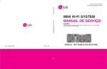
Location of PC Boards
CD PART
CD Board
Tuner Board
Display Board
Main Board
BT Board
Key Board
MCU Board
Light Board
USB Board
EQ Board
AC Cord
MIC/PC IN/AUDIO IN Board
SMPS Board
Amp Board
VERSION VARIATION
FWM9200
Type /Versions:
Board in used:
Service policy
/55
x/77 x/78
(LATAM)
(ARGENTINA)
(BRAZIL)
Main BOARD
Display BOARD
Amp BOARD
Key BOARD
Mic BOARD
C/M
C/M
C/M
C/M
C/M
C/M
C/M
C/M
C/M
C/M
C/M
C/M
C/M
C/M
C/M
Tuner BOARD
SMPS BOARD
CD BOARD
MCU BOARD
C/M C/M C/M
M
M
M
C/M C/M C/M
C/M C/M C/M
Type /Versions:
Features
Feature diffrence
RDS
VOLTAGE SELECTOR
ECO STANDBY - DARK
* TIPS : C -- Component Lever Repair.
M -- Module Lever Repair
√ -- Used
FWM9200
/55
x/77 x/78
C/M
C/M
1-3
FWT9200 SH 190 content List
No.
Descrpitopn
*(1(5$/3$57)52173$11(/63(&,&),&$7,21
*(1(5$/3$57%$&.3$11(/63(&,&),&$7,21
*(1(5$/3$57*(1(5$/63(&,&),&$7,21
*(1(5$/3$577(&+1,&$/63(&,&),&$7,21
*(1(5$/3$57$8',26,*1$/63(&,&),&$7,21
*(1(5$/3$57$8',26,*1$/63(&,&),&$7,21
*(1(5$/3$57&/2&.7,0(563(&,&),&$7,21
*(1(5$/3$5786%6'&DUG63(&,&),&$7,21
*(1(5$/3$57781(563(&,&),&$7,21$OO
*(1(5$/3$57&'0363(&,&),&$7,21
*(1(5$/3$57%763(&,&),&$7,21
*(1(5$/3$570LFURKRQH63(&,&),&$7,21
*(1(5$/3$579(56,2129(59,(:63(&,&),&$7,21
Issue: Andy Lai
Checked:
DATE: 2012-12-21
Page
DEPICTION
1 2
38
3
4 5
39
6
37
36
7
35
8
9
10
11
12
34
33
32
31
13
30
14
15
29
28
16
27
17
18
26
19
25
24
23
22
21
20
Pos
1
2
3
4
5
6
7
8
9
10
11
12
13
14
15
16
17
18
19
20
21
22
23
24
25
26
27
28
29
30
31
32
33
34
35
36
37
38
39
Description
DISC CHANGE
DISC1
DISC2
DISC3
OPEN/CLOSE
|<TITLE PRESET
TITLE>|PRESET
>||(PLAY/PAUSE)
PROGRAM/TIMER
VAC
DBB
TUNER
IR LENS
AUX/LINE
DISPLAY
MIC VOL
MIC 1 JACK
MIC2 JACK
ECHO VOL
ROCK
OTPIMAL
MAX SOUND
TECHNO
JAZZ
USB RECORD
LINE IN
USB JACK
USB DEL
LIGHT
USB
DISC
IS
POWER ON/OF
MODE
STOP
<<ALBUM--SEARCH.TUNING
ALBUM>>SERCH.TUNING
VOL
VFD DISPLAY
Page
CABINET
Material : HIPS / ABS / POM / V2 / SAN
Finshing : Chrome Plate
Units in Masstercarton
Units in Dealercarton
Diemensions with Boxes ( wxhxd ) 265mm X 382mm X 345mm
Diemensions without Boxes ( wxhxd ) 1250mm X 340mm X 495
Weight ( inclusive packing )8.505KG
Weight ( exclusive packing & batery )26KG
Remarks :
1 used into
Remark :
GENERAL PART 1 - FRONT PANNEL SPECICFICATION
Class No
FWT9200 All Version
NAME :
11
CHECK:
DATE :
11
SH 190 - 1
Ver
Issued Date
1
2
3
21-Dec-12
A4
1-5
DEPICTION
10
1
2
3
4
7
6
5
8
13
12
9
11
10
14
Pos
1
2
3
4
5
6
7
8
9
10
11
12
13
14
15
16
17
18
19
20
21
22
23
24
25
26
27
28
Description
A.M. Antenna
F.M. Anntena
Aux Input
for subwoofer
AC INTPUT
voltoge selector
FAN
LOW /HIGH Left / Right Speaker Socket
sub FAN
SUB Aux Input
SUB voltoge selector
LS RS Speaker Socket
for MAIN
POWER SW
Page
CABINET
Diemensions with Boxes ( wxhxd )265mm X 382 mm X 345 mm
Diemensions without Boxes ( wxhxd ) 1250mm X 340mm X 495mm
Weight ( inclusive packing )8.5Kg
Weight ( exclusive packing & batery )26Kg
Material :HIPS
Finshing : Chrome Plate
Units in Masstercarton
Units in Dealercarton
GENERAL PART 1 - BACK PANNEL SPECICFICATION
Class No
Ver
1
2
3
FWT9200 All Version
NAME :
10
CHECK:
DATE :
10
SH 190 - 2
Issued Date
A4
1-6
GENERAL DESCRIPTION
MP3-USB Mini Hi FiSystem with Digital Tuner, 3CD/MP3
(2x360W+2x360W+2x180W) For FWT9200 Power Amplifier,VFD Display,Aux in ,Remote control
Subwoofer Boxes of 8 Ohm x 2
LIFETIME : 7 Years
Class
Tuner
Supply + Amplifier
USB
Recorder
Clock
CD-mp3
I
II
X
X
X
X
X
X
8
11
III
10
3-6
Page
SAFETY requirements
Version
Safety
/98
EN 60065,
/55
EN 60065,EN61000-3-2/EN61000-3-3
/12
EN 60065
/05
EN 60065
EN 60065
/79
/37
UL 60065
9
EMC
CISPR 13
CISPR 13
EN 55013 / EN 55020
EN 55013 / EN 55020
CISPR 13
FCC99
RADIATION / IMMUNITY requirments ( EMC ) for 12 version only
CLIMATIC requirements
ALL climates
MODERATE climates
PERFORMANCE CLASSES
: + 5 Dregree
: + N.A
till
till
+ 35 Degree
N.A Degree
POWER SUPPLY (SWITCHING MODE POWER SUPPLY)
MAINS ( A.C. )
SWITCH POWER FOR AC100V TO 250V
Version
Voltage Selection
Frequency
POWER CONSUMPTION
Standby(with display) :
( DEMO mode " OFF " ) , NOM. A, INPUT
Maximum :
@ 1/8 Prated , NOM. A, INPUT
ECO Power mode(Without display):
/ 12/ 05
< 1W
/ 55/77/78/98
Ref. to CRS
/61 /93
Ref. to CRS
/ 37
< 1W
< 250W
< 0.5W
Ref. to CRS
Ref. to CRS
< 0.5W
Quality
: 0.8 % ( Major )
2.0 % ( Mirror )
Reliability
: 3.0 % ( C 42 )
Tested according to General Test Instruction refer to PHILIPS standary ( UAN -D1591 )
Measured according to PHILIPS standary ( UAN - L1059 ) unless other wise stated
All not mentioned date, please refer to PHILIPS standary ( XUW - 0010 - JUNE 2001 )
DERIVED
REMARKS
APPROBATION
Remarks
GENERAL PART 1 - GENERAL SPECICFICATION
Class No
Ver
1
2
3
FWT9200 All Version
NAME : Andy Lai
10
CHECK
DATE :
10
SH 190 - 3
Issued Date
21-Dec-12
A4
1-7
TECHNIAL DESCRIPTION
Total power 1800W, matching LOUDSPEAKER of 4 x 8 Ohm +2 x 4 Ohm. INPUT SOURCE, CD/MP TUNER USB AUX 3DSC ( Digital Sound Control ). IS
( Incredible Sound )
GENERAL PART
OUTPUT stage Protection
LoudSpeaker D.C. Protection
INDICATORS
Standby Mode Indicator
ECO Mode Indiicator
: Yes
: Yes.
Temperature
: Yes.
Shorcircuit
: Yes
: FTD display Clock active
: FTD turns off, ECO - Standby LED turn on
ELECTRICAL DATA (Main computer )
DSC : Rock, Pop, Jazz, Optimal
MAX YES
IS :
YES
VAC : N/A
WOOX : N/A
Channel Differencer at -40dB
Hum ( Volume control from min. till max. – 20 dB)
Residual Noise ( Volume Minium )
Channel Separation ( at 1 kHz )
Signal / Noise ( unweighted )
Subwoofer Out Hum( Volume minmun)
dB
nW
nW
dB
dB
µW
3
< 200
< 60
ı 45
ı 55
<4
INTERCONNECTS
Input Sensitity(±2 dB)rated ouput power at 1 kHz and 10kHz.
Line Output Voltage ( *1 )
Tuner
CD
: FM 67.5KHZ AM80% Modulation
: 0 dB track ( Audio Disc 1, Trk 35 )
Line Out ( Left / Right )
Subwoofer Out
USB
: 0 dB track ( Audio Disc 1, Trk 35 )
: Nor: 600mV Lim: 350mV ~ 900mV for /37
: Nor: 2V Lim: 1.5V ~ 2.5V for /55
Headphone
Digital Coaxial Out
Booster Out
AUX
Microphone
:
input leven 1mv rms(lim:2.5mv rms)
Rs=600ohm
N.A
Yes
0DLQ&KDQQQHO
68%&KDQQHO
5HDUFKDQQHO
Frequency response @±4dB
0.7V +/- 0.2% at 32 Ohm
N.A
N.A
+=.+=UHIHUHQFH.+=
+=+=UHIHUHQFH+=
+=.+=UHIHUHQFH.+=
output power 1kHz
OUTPUT POWER ( * 1 )At THD = 10% (Measured with 20Hz-20KHz filter),(Per Channel measuremend )
Power output ( RMS )
L/R channel
360W ( Lim '-1dB )
Power output ( RMS )
Power output ( RMS )
Power output ( RMS )
Tuner output ( Lim '-6dB )
L/R Subwoofer channel
L/R Rear channel
360W ( Lim '-1dB )
180W ( Lim '-1dB )
LOUDSPEAKER ( BOXES )
Please to package document of Speaker Box Assy
Rated Impedance
FRONT:L/R : 8 Ohms X2 at 40Hz to 16 KHz
Subwoofer L/R : 8 Ohm x2 at 40HZ to 100HZ
Rear: L/R :
4 Ohms X2 at 200Hz to 16 KHz
Remarks
( *1 )
Measurement output power just connect 1 channel loads (Per channel measurement).
Electrical parameters are to be measuremend at specker terminals across 8 Ohm load ( pure resistor )
with rated input signal in AUX mode; DSC setting in Jazz mode with DBB OFF
IS off and OSM unless specified otherwise
Measurement output power only for AUX model and CD model of used audio analyzer equipment.
(*2)
All speaker "R" channel "+ "connect to equipment " + "for measurement.
All speaker "L" channel "- "connect to equipment " + "for measurement (because all "L"channel output are reverse ).
GENERAL PART 1 - TECHNAICAL SPECICFICATION
Class No
FWT9200 All Version
NAME : Andy Lai
10
CHECK
DATE :
10
SH 190 - 4
Ver
1
2
3
Issued Date
21-Dec-12
A4
1-8
AUDIO SIGNAL PROCESSING
MP3-USB Mini Hi Fi System with Digital Tuner , 3 CDC-MP3,(Main:2×3+60W+Rear:2×180W+SUB:2x360W) Universal Class D Power Amplifier
1)
DSC ( Digital Sound Control )
Select AUX as input source with the following set conditions:
Inject sine wave 500mV at 1 KHz to L/R channels of AUX-IN socket.
Set DSC to JAZZ(Flat) mode and switch off DBB.
Refence level for DSC's without DBB on=1W.
Refence level for DSC'S with DBB on=1.2V at the speaker terminal .
Inject sine wave 500mV-2.4V to AUX-IN socket with frequencies indicated in Table 1.
For FWM998 Subwoofer in put 500mW 60HZ @ 3R (Main computer )
Tabel 1a ( Tolerance ± 3dB )
DSC Modes with DBB Off
Frequency
JAZZ
POP
TECHNO
60 Hz (SUB)
0
4
6
2
1K((SUB)
0
0
0
0
1 kHz (host computer)
0
0
0
0
10 kHz(host computer)
0
2
-4
2
JAZZ
POP
TECHNO
OPTIMAL
60 Hz (SUB)
4
8
8
6
1khz(SUB)
0
0
0
0
1 kHz (host computer)
0
0
0
0
10 kHz (host computer)
0
2
-4
2
JAZZ
POP
TECHNO
OPTIMAL
60 Hz (SUB)
10
16
16
13
1 kHz(SUB)
0
0
0
0
1khz (host computer)
0
0
0
0
10 kHz (host computer)
0
4
-2
2
JAZZ
POP
TECHNO
OPTIMAL
60 Hz (SUB)
16
20
20
20
1khz(SUB)
0
0
0
0
1 kHz(host computer)
0
0
0
0
10 kHz(host computer)
2
6
0
4
OPTIMAL
Tabel 1b ( Tolerance ± 3dB )
DSC Modes with DBB 1 ON
Frequency
Tabel 1b ( Tolerance ± 3dB )
DSC Modes with DBB 2 ON
Frequency
Tabel 1b ( Tolerance ± 3dB )
DSC Modes with DBB 3 ON
Frequency
2)
DBB ( Dynamic Bass Boot )
Select AUX as input source with the following set conditions :
Inject sine wave 500mV at 1kHz to L/R channels of AUX - IN socket.
Set DSC to JAZZ(Flat) mode and switch off DBB,
Reference level for the test is 500mW on the speaker terminals.
Tabel 2 of FWM998( Tolerance ± 3dB )
Frequency
DBB OFF
DBB 1
DBB 2
DBB 3
60 Hz(SUB)
0
4
8
12
1 Hz(SUB)
0
0
0
0
1khz(host computer)
0
0
0
0
10K Hz(host computer)
0
0
0
2
GENERAL PART 1 - GENERAL SPECICFICATION
Class No
FWT9200 All Version
Ver
Issued Date
1
21-Dec-12
2
3
10
NAME : Andy Lai
CHECK
DATE :
10
SH 190 - 5
A4
1-9
AUDIO SIGNAL PROCESSING
MP3 - USB Mini Hi Fi System with Digital Tuner , 3 CDC-MP3, (Main:2×360W+SUB:2×360W+Rear:2x180W) Universal Class D Power Amplifier
3)
IS ( Incredible Sound )
Select AUX as input source.
Inject sine wave 2V at 1kHz to AUX-IN socket, two channel at a time (input level 600mV for /37,2V for /55 ).
Set DSC to JAZZ ( Flat ) mode and switch of DBB, OSM & INCREDIBLE SURROUND.
Adjust volume level to obtain 1W across 3 OHM load at L/R speaker output.
Inject sine wave 2V to AUX-IN socket withfrequency indicated in Table 3 (input level 600mV for /37,2V for /55 ).
Table 3 ( Tolerence ± 3 dB )
OUTPUT LEVEL
INPUT LEVEL
FREQ
IS OFF
IS ON
LEFT
RIGHT
LEFT
RIGHT
LEFT
RIGHT
60 Hz
2V
-
- 1.0 dB
-
+2.0 dB
- 15 dB
1 kHz
2V
-
0
-
+ 3.5 dB
0 dB
10 kHz
2V
-
- 0.5 dB
-
+ 3.0 dB
-5 dB
Note : The above specs also apply to right channel.
4)
DSC Mode ( Jazz , Rock, Techno and Optimal )
The VEC modes are software controlled by switching the combination between DBB and DSC modes
as show in Table 4.
VEC MODE
DBB Level preset
Jazz
DBB OFF
POP
DBB 3
Techno
Optimal
DBB 3
DBB 2
Note : When these modes are activ DBB and DSC will not be displayed
5)
MAX ( Maximum Sound )
Select AUX as input source.
Inject sine wave 2V at 1kHz to AUX-IN socket, one channel at a time (input level 600mV for /37,2V for /55 ).
Set DSC to JAZZ ( Flat ) mode and switch of DBB, OSM & INCREDIBLE SURROUND.
Adjust volume level to obtain 1W across 3 OHM load at L/R speaker output.
The 1W level will be used as 0 dB reference
Inject sine wave 2V to AUX-IN socket withfrequency indicated in Table 5 (input level 600mV for /37,2V for /55 ).
FREQ
60 Hz
Max OFF
-1
Max ON
+19
1 kHz
0
-1
10 kHz
GENERAL PART 1 - AUDIO SIGNAL SPECICFICATION ( 2 )
Class No
FWT9200 All Version
Ver
Issued Date
1
21-Dec-12
2
3
NAME : Andy Lai
10
CHECK
DATE :
10
SH 190 - 6
A4
1-10
TECHNIAL DESCRIPTION
SOFTWARE IMPLEMENTED CLOCK / TIMER FUNCTION WITH 12MHZ QUARTZ OSCILLATOR.
GENERAL PART
Timer Setting
:
Clock and Timer
Timer Wakeup Mode
:
CD or Tuner or USB
Remarks Time Setting
:
12hr for /37 version, 24hrs for other version.
Volume at Wakeup
:
Last Setting
1RRI7LPHU6HWWLQJV
:
1
&ORFN$FFXUDF\
:
Nom : 1 sec/day
Limit
: 2 sec/day
,1',&$7256
'LVSOD\7\SH
9)'
Remark
CLOCK / TIMMER SPECICFICATION
Class No
FWT9200 All Version
Ver
Issued Date
1
2012-21-21
2
3
NAME : Andy Lai
10
CHECK
DATE :
10
SH 190 - 7
A4
1 - 11
TECHNIAL DESCRIPTION
USB
See also SH 190 USB Audio Module (300605)
Measurment are directly done at the coonector on the board
GENERAL PART
Measurement are directly done at the connector on CDC board
Description
Specification
Output Resistance
< = 1.5 kOhm
Output Voltage RL = 33 k ohm ( )dB, 1 Khz )
830mV/- 1dB
Channel Unbalance
< = +/- 3 dB
THD + Noise ( 0dB, 1Khz )
<=2%
Channel Crosstalk ( ( 0 dB, 1 KHz ) )
>= 45dB
( 0 dB, 1 KHz )
>= 45dB
Signal to Noise Ratio ( 0dB,1kHz ) ( A - weighted )
>= 55dB( A - weighted )
40HZ-16KHZ(reference 1KHZ)
FWT9200 Frequency response @±4
40HZ-100HZ(Reference 63HZ)
200HZ-16KHZ(Reference 1KHZ)
USB Measurement at Set Level (*2)
Electrical Parameters are to be measured at speaker teminals across 3 ohm load with 500mW output and DSC setting in Jazz Mode
Description
Specification
Channel Crosstalk ( 0 dB, 1 KHz )
>= 45dB (with 1 KHz filter )
Signal to Noise Ratio ( 0 dB, 1 KHz )
>= 55dBA ( A - weighted )
Channel Unbalance ( 0 dB, 1 KHz )
< +/- 3dB
SD-CARD Measurement at Set Level (*2)
Electrical Parameters are to be measured at speaker teminals across 3 ohm load with 500mW output and DSC setting in Jazz Mode
Description
Specification
Channel Crosstalk ( 0 dB, 1 KHz )
>=45dB (with 1 KHz filter )
Signal to Noise Ratio ( 0 dB, 1 KHz )
>= 55dBA ( A - weighted )
Channel Unbalance ( 0 dB, 1 KHz )
< +/- 3dB
Remarks :
$OOVSHDNHU5FKDQQHOFRQQHFWWRHTXLSPHQWIRU
PHDVXUHPHQW
$OOVSHDNHU/FKDQQHOFRQQHFWWRHTXLSPHQWIRUPHDVXUHPHQW
EHFDXVHDOO/FKDQQHORXWSXWDUHUHYHUVH
USB AND SD-CARD SPECICFICATION
Class No
FWT9200 All Version
Ver
Issued Date
1
21-Dec-12
2
3
NAME : Andy Lai
10
CHECK
DATE :
10
SH 190 -8
A4
1 - 12
TECHNIAL DESCRIPTION
TUNER used SI4730 soultion
GENERAL PART
WAVE RANGE
FM( 55/37 )
87.5
FM( 12 )
87.5 AM (55/37)
530
AM (12)
531 AERIAL
FM
:
AM
:
TOLERANCE
QUARTZ PRECISION
- 108.00 MHz
108.00 MHz
- 1700
kHz
1602
kHz
TUNING GRID
100 kHz
50KHZ
10 kHz
9 kHz
QUARTZ PRECISION
QUARTZ PRECISION
PIGTAIL ANT WIRE 300 Ohm(for/37)
FRAME ANT. 18.1 uH with shielding
75ohm for 55/12
INDICATORS
VFD
Nom
A.M
Limit
Unit
F.M.
- 3 dB Limiting Point
Distortion ( RF 50mV, M 80% )
:
:
:
-2
30
3
-4
25
5
dB Amplification Reverse
dB Distortion ( RF 1mV, Frq Dev.75 kHz )
% Stereo - 46 dB Quieting
IF
:
450
±3
kHz Crosstalk (RF1mV, Freq Dev.40kHz )
Amplification Reverse
AGC Figure of Merit
IF
:
Search Tuning Sensitivity
S/N Ratio
MW 610 kHz
MW 1440 kHz
FM 98 MHz
FM 108 MHz
Nom
17
0
2
46
Limit
23.5
-4
3
49
Unit
dBf
dB
%
dBf
:
25
18
dB
:
10.7
± 0.03
MHz
ɲ26
+/-10
dB
24-30
19-35
dBf
45
40
dB
50
45
dB
Noise Limited Sensitivity Į26 dB
Wave Range
:
:
:
:
Image Rejection
IF Rejection
Large Signal
Selectivity
S9 / 300kHz
Nom.
3500
uV/m
32 db
28db
1000mv/m
22db
Lim.
4000
Uv/m
28db
24db
500mv/m
18db
Nom.
1500
uV/m
32db
28db
1000mv/m
22db
Lim.
4000
uV/m
28db
24db
500mv/m
18db
Nom.
18
dBf
40db
65db
116 dBu
30db
Lim.
22
dBf
30db
60db
108 dBu
25db
Nom.
18
dBf
40db
65db
116 dBu
45db
Lim.
22
dBf
30db
60db
108 dBu
25db
Remarks˖MAX.Sens -6dB
TUNER SPECICFICATION
Class No
FWT9200 All Version
Ver
Issued Date
1
21-Dec-12
2
3
NAME : Andy Lai
10
CHECK
DATE :
10
SH 190 - 9
A4
1 - 13
TECHNIAL DESCRIPTION
CD + MP3 - Part Specifications (CD MECHAISM DA11VF OF SANYO )
Input
Output
Motor
Logic control
Signal processsing
D/A converter
HF-preamplifier
Servo processor
Active components
Active components
AUDIO part: Measurement with Audio Signals Disc-783 7104 078 04911 on spkeakers or Headphone socket with nom.load
Description
Extern Filter
Nom
Unit
Lim
15us / 50us Switchable via Subcode information
De-emphasis
Frequency accuracy
N/A
± 0.5
%
Channel Unbalance
1
3
dB
Frequency Response
requency Response
L/R
( 40 Hz - 16 kHz ) reference 1kHz
)5217&+
5HDU&+
68%&+
( 200Hz - 16 kHz )reference 1kHz
Frequency Response
( 40Hz - 100Hz ) reference 63Hz
'± 4
L/R
Signal to Noise Ration ( A - weighted )
dB
± 4
L/R
Signal to Noise Ration ( Unweighted )
dB
dB
60
50
dBA
65
55
dBA
Crosstalk ( 1kHz ) ( A - weighted )
>= 45dB
Hum & Noise (filer 20kHz) ( *1 )
1
dB
dB
1.5
mV
THD (1KHz -6dB)
0.2
<1
%
THD (10KHz -20dB)
<1
<3
%
REMARKS:
1. Amplification reserve for CD = +2dB ('±2dB),Ref.Level for CD is a 0dB track instead of a .-6dB track.
Playability :(acc.To AR 30-05-239 )
Wedge
Limit
Typical
Test disc
600um
900um
TNO 7, 9 of SBC 444A(7104 099 24990)
200um
TNO 1, 24 of 200um disc (7104 099 24960)
800um
TNO 13 of SBC 444A (7104 099 24990)
Eccentric
150um
Fingerprint
No audible defect
Black dot
500um
TNO 11 of Sub chassis 8A
Skew 0.6mm
No audible defect
Bad HF track
No audible defect
TNO 8 of Sub chassis 8A
Hwavy fingerprint
No track jumper/plops
TNO 10 of Sub chassis 8A
Playback position
TNO 1,6 of 0.6mm skew (7104 099 28260)
Solid, Normal position (Set is located on a flat surface, floor)
1. Playback of above mentioned tracks possible wihout track loss or audible defects.
2. Double black dot, max. diameter, thin/disk is according to PQR or AR 30-05-239
3. This unit can playback (only) CD-R or CD-RW discs. For performance specification, Please refer to module.
specification of CD99 (3103 308 52190)
Remarks :
4. (1)All speaker "R" channel "+ "connect to equipment " + "for measurement.
(2) All speaker "L" channel "- "connect to equipment " + "for measurement (because all "L"channel output are reverse ).
CD / MP3 SPECICFICATION
Class No
Ver
1
2
3
FWT9200 All Version
10
NAME : Andy Lai
CHECK
DATE :
10
SH 190 -10
Issued Date
21-Dec-12
A4
1 - 14
TECHNIAL DESCRIPTION
Bluetooth Function
GENERAL PART
Bluetooth Version :
Ver2.1 + EDR
Receive A2DP:
N/A
Transmit A2DP:
N/A
Remote Controlled
:
N/A
Receive HSP
N/A
Noise Reduction System
:
No
INDICATORS
Bluetooth Flashing
Display
:
:
Yes
N/A
ELECTRICAL DATA
Bluetooth at Module level:
Mobile Phone
lim
Unit
dB
125-16khz
f
S/N (Unweighted)
ı
dB
S/N (A-weighted)
ı
dBA
?
f
dB
ı
dB
Frequency Response
Level Diff
Channel Separation
˘
Distortion
Bluetooth at Set Level
λ
Mobile Phone
10%THD OUTPUT POWER(EQ:FLAT)
\
Connected distance
Per channel test total:1800
8~10
W
meter
REMARKS
Bluetooth SPECICFICATION
Class No
Ver
1
2
3
FWT9200 All Version
NAME : Andy Lai
DATE :
CHECK:
DATE :
SH 190 - 11
Issued Date
21-Dec-12
1 - 15
TECHNIAL DESCRIPTION
Microphone
See also SH 190 testing with 20 to 20k Hz filter,input leven 1mv rms(lim:1.5mv rms) Rs=600ohm output 500mW
Measurment are directly done at the coonector on the board
GENERAL PART
Measurement are directly done at the connector Microphone(mic1,mic2)
Description
Specification
Nom
Output Resistance
N/A
Output Voltage RL = 33 k ohm ( )dB, 1 Khz )
N/A
Lim
Unit
Channel Unbalanceo about( mic1 and mic2)
1
+/- 3
dBA
THD + Noise ( 0dB, 1Khz )vol max
6
8
%
Channel Crosstalk ( ( 0 dB, 63Hz ) )
N/A
( 0 dB, 1 KHz )
N/A
Signal to Noise Ratio ( 0dB,1kHz ) ( A - weighted )
45
40
dBA
Microphone Power output( RMS )
mW
550
+/- 20%
Microphone input leven ( Rms)
1
1.5
mV
Max Hum Noise(mic vol max,main vol max)
6
8
mV
Vol.min=vol1.(mic vol min,main vol 1)
2
4
mV
Microphone Frequency response
volume 23,input leven 1mv rms,
connect main load
at
)/)5FK
+=
±4
dB
.+=
ref
dB
.+=
±3
dB
Remarks :
testing with 20 to 20k Hz filter
USB SPECICFICATION
Class No
FWT9200 All Version
Ver
Issued Date
1
21-Dec-12
2
3
NAME : Andy Lai
12
CHECK
DATE :
9
SH 190 -9
A4
1 - 16
VERSION OVERVIEW FWT9200
APPROBATION
Ver
TUNER
MAT
MIC RIX
MIX SURR
SOC. CORD
. SPK.
AC SUPPLY
DEST
SAFETY
EMC
Wave RANGE
GRID
AERIAL SOCKET
AERIAL SUPPLIED
MAINS
VOLTAGE
OVS
EN60065
CLASS II
SISR
TAIWAN
CISPR 13
FM 87.5-108MHz MW
531-1602kHz
or 530-1710kHz
50kHz
9kHz
10kHz
75 Ohm Coaxial
JST XH 2P Side
75 Ohm Pigtail
Loop Sagami 18.1uH
110-127V
Switched
220 - 240V
50/60Hz
IEC
IEC
No
No
/05 / 12
EUROPE
EN60065
SEMKO
DEMKO
NEMKO SEV
BS415-UK
EN55013
EN55020
FM 87.5-108MHz MW
531-1602kHz
50kHz
9kHz
75 Ohm Coaxial
JST XH 2P Side
75 Ohm Pigtail
Loop Sagami 18.1uH
230V
50Hz
IEC
IEC
No
No
/79
AUST / NZ
EN60065
CLASS II
FM 87.5-108MHz MW
531-1602kHz
50kHz
9kHz
75 Ohm Coaxial
JST XH 2P Side
75 Ohm Pigtail
Loop Sagami 18.1uH
240V
50Hz
IEC
IEC
No
No
/37
USA
Canada
UL 6500
FM 87.5-108MHz MW
530-1710kHz
100kHz
10kHz
JALCO Click Fit
JST XH 2P Side
300 Ohm Dipole
Loop Sagami 18.1uH
120V
60Hz
UL
UL
No
No
/35
China
EN60065
CLASS II
FM 87.5-108MHz MW
531-1602kHz
50kHz
9kHz
75 Ohm Coaxial
JST XH 2P Side
75 Ohm Pigtail
Loop Sagami 18.1uH
220V
60Hz
IEC
IEC
No
No
/ 33
Korea
EN60065
CLASS II
FM 87.5-108MHz MW
531-1602kHz
50kHz
9kHz
75 Ohm Coaxial
JST XH 2P Side
75 Ohm Pigtail
Loop Sagami 18.1uH
220V
60Hz
IEC
IEC
No
No
/55 /77/78/98
FCC 99
5HPDUN
$0GHIDXOWLV.LQ$0PRGHWLJKWSUHVV6723EXWWRQFDQFKDQJHWR.
VERSION OVERVIEW
Class No
Ver
1
2
3
FWT9200 All Version
NAME : Andy Lai
10
CHECK
DATE :
10
SH 190 - 13
Issued Date
21-Dec-12
A4
2-1
2.0 SAFTETY INSTRUCTIONS
GB
NL
ESD
WARNING
Alle IC’s en vele andere halfgeleiders zijn
gevoelig voor electrostatische ontladingen
(ESD).
Onzorgvuldig behandelen tijdens reparatie kan
de levensduur drastisch doen verminderen.
Zorg ervoor dat u tijdens reparatie via een
polsband met weerstand verbonden bent met
hetzelfde potentiaal als de massa van het
apparaat.
Houd componenten en hulpmiddelen ook op
ditzelfde potentiaal.
All ICs and many other semi-conductors are
susceptible to electrostatic discharges (ESD).
Careless handling during repair can reduce life
drastically.
When repairing, make sure that you are
connected with the same potential as the mass
of the set via a wrist wrap with resistance.
Keep components and tools also at this
potential.
F
ATTENTION
Tous les IC et beaucoup d’autres
semi-conducteurs sont sensibles aux
décharges statiques (ESD).
Leur longévité pourrait être considérablement
écourtée par le fait qu’aucune précaution n’est
prise à leur manipulation.
Lors de réparations, s’assurer de bien être relié
au même potentiel que la masse de l’appareil et
enfiler le bracelet serti d’une résistance de
sécurité.
Veiller à ce que les composants ainsi que les
outils que l’on utilise soient également à ce
potentiel.
WAARSCHUWING
D
I
WARNUNG
Alle ICs und viele andere Halbleiter sind
empfindlich gegenüber elektrostatischen
Entladungen (ESD).
Unsorgfältige Behandlung im Reparaturfall kan
die Lebensdauer drastisch reduzieren.
Veranlassen Sie, dass Sie im Reparaturfall über
ein Pulsarmband mit Widerstand verbunden
sind mit dem gleichen Potential wie die Masse
des Gerätes.
Bauteile und Hilfsmittel auch auf dieses gleiche
Potential halten.
AVVERTIMENTO
Tutti IC e parecchi semi-conduttori sono
sensibili alle scariche statiche (ESD).
La loro longevità potrebbe essere fortemente
ridatta in caso di non osservazione della più
grande cauzione alla loro manipolazione.
Durante le riparazioni occorre quindi essere
collegato allo stesso potenziale che quello della
massa dell’apparecchio tramite un braccialetto
a resistenza.
Assicurarsi che i componenti e anche gli utensili
con quali si lavora siano anche a questo
potenziale.
GB
Safety regulations require that the set be restored to its original
condition and that parts which are identical with those specified,
be used.
“Pour votre sécurité, ces documents
doivent être utilisés par des spécialistes agréés, seuls habilités à réparer
votre appareil en panne”.
NL
Veiligheidsbepalingen vereisen, dat het apparaat bij reparatie in
zijn oorspronkelijke toestand wordt teruggebracht en dat onderdelen,
identiek aan de gespecificeerde, worden toegepast.
CLASS 1
LASER PRODUCT
3122 110 03420
F
Les normes de sécurité exigent que l’appareil soit remis à l’état
d’origine et que soient utiliséés les piéces de rechange identiques
à celles spécifiées.
GB
Warning !
Invisible laser radiation when open.
Avoid direct exposure to beam.
D
Bei jeder Reparatur sind die geltenden Sicherheitsvorschriften zu
beachten. Der Original zustand des Geräts darf nicht verändert werden;
für Reparaturen sind Original-Ersatzteile zu verwenden.
I
Le norme di sicurezza esigono che l’apparecchio venga rimesso
nelle condizioni originali e che siano utilizzati i pezzi di ricambio
identici a quelli specificati.
"After servicing and before returning set to customer perform a
leakage current measurement test from all exposed metal parts to
earth ground to assure no shock hazard exist. The leakage current
must not exceed 0.5mA."
S
Varning !
Osynlig laserstrålning när apparaten är öppnad och spärren
är urkopplad. Betrakta ej strålen.
SF Varoitus !
Avatussa laitteessa ja suojalukituksen ohitettaessa olet alttiina
näkymättömälle laserisäteilylle. Älä katso säteeseen!
DK Advarse !
Usynlig laserstråling ved åbning når sikkerhedsafbrydere er
ude af funktion. Undgå udsaettelse for stråling.
Caution: These servicing instructions are for use by qualified service personnel only.
To reduce the risk of electric shock do not perform any servicing other than that contained in the operating instructions unless you are qualified to do so.
2-2
2.1 ESD PROTECTION
Whenthepowersupplyisbeingturnedon,youmaynotremovethislasercautionslabel.Ifitremoves,radiationoflaser
maybereceived.
PREPARATIONOFSERVICING
PickupHeadconsistsofalaserdiodethatisverysusceptibletoexternalstaticelectrocity.
Althoughitoperatesproperlyafterreplacement,ifitwassubjecttoelectrostaticdischargeduringreplacement,
itslifemightbeshortened.Whenreplacing,useaconductivemat,solderingironwithgroundwire,etc.to
protectthelaserdiodeformdamagebystaticelectricity.
Andalso,theLSIandICaresameasabove.
Groundconductive
wriststrapforbody.
Solderingiron
withgroundwire
orceramictype
1M
Conductivemat
Thegroundresistance
betweenthegroundline
andthegroundislessthan10
2-3
SAFTY NOTICE
SAFTY PRECAUTIONS
LEAKAGE CURRENT CHECK
Plug the AC line cord directly into a 120V AC outlet (do
Measure the AC voltage across the 1500
not use an isolation transformer for this check). Use an
AC voltmeter, having 5000 per volt or more sensitivity.
The test must be conducted with the AC switch on and
then repeated with the AC switch off. The AC voltage
Connect a 1500
indicated by the meter may not exceed 0.3V.A reading
10W resistor,paralleled by a 0.15uF
resistor.
150V AC capacitor between a knomn good earth ground
(water pipe, conduit, etc.) and all exposed metal parts of
exceeding 0.3V indicates that a dangerous potential
exists, the fault must be located and corrected.
cabinet (antennas, handle bracket, metal cabinet
screwheads, metal overlays, control shafts, etc.).
Repeat the above test with the DVD VIDEO PLAYER
power plug reversed.
NEVER RETURN A DVD VIDEO PLAYER TO THE
CUSTOMER WITHOUT TAKING NECESSARY
CORRECTIVE ACTION.
READING SHOULD NOT EXCEED 0.3V
AC VOLTMETER
DVD VIDEO PLAYER
(5000 per volt
or more sensitivity)
1500
10W
AC OUTLET
Good earth ground
such as a water pipe,
conduit, etc.
0.15uF 150V AC
Test all exposed metal.
Voltmeter Hook-up for Leakage Current Check
The lightning flash with arrowhead symbol, within an
equilateral triangle, is intended to alert the user to the
presence of uninsulated "dangerous voltage" within the
product's enclosure that may be of sufficient magnitude to
constitute a risk of electric shock to persons.
The exclamation point within an equilateral triangle is
intended to alert the user to the presence of important
operating and maintenance (servicing) instructions in the
literature accompanying the appliance.
2-4
2.2 SAFETY INSTRUCTIONS
Battery Handling Guideline
Since the battery is packed in soft package, to ensure its good performance, it’s very important to carefully handle
the battery
2.2.1 Soft Aluminium foil
The soft aluminum packing foil is very easily damaged by sharp edge parts such as Ni-tabs, pins and needles.
• Don’t strike battery with any sharp edge parts
• Trim your nail or wear glove before taking battery
• Clean worktable to make sure no any sharp particle
2.2.2 Sealed edge
Sealing edge is very flimsy
• Don’t bend or fold sealing edge
2.2.3 Folding edge
The folding edge is formed in battery process and has passed all hermetic tests.
• Don’t open or deform folding edge
2.2.4 Tabs
The battery tabs are not so rigid especially for aluminum tab.
• Don’t bend tab
2.2.5 Mechanical shock
• Don’t fall, hit, bend battery body
2.2.6 Short
Short terminals of battery is strictly prohibited, it may damage battery.
Caution: Danger of explosion if battery is incorrectly replaced.
Replace only with the same or equivalent type.
The battery shall not be exposed to such as sunshine, fire or similar overheated environment.
如果电池更换不当会有爆炸危险 , 只能用同样类型或等效类型的电池来更换.
电池不得暴露在诸如日照、火烤或类似过热环境
3-1
3-1
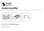
BLOCK DIAGRAM
VFD Board
VFD Display
CD DOOR MOTOR
CD Board
AC CORD
TUNER
(SI4730/31 )
VFD DRIVER
LED DRIVER
PT6311
IIC
3CD LOADER
BU2090F
IIC
POWER Board
MOTOR DRIVER
CD DOOR
DRIVER IC
AM5888S
PICK UP
TA7291S
FWM998/ FWM9000
8M SERIAL
FALSH
SST29VF080B
For 1000W
MOTOR
CONTROL DATA
BT MODULE
CD SERVO
BU9543
MLC3895
SWITCH POWER SUPPLY
144pin QFP
16M SDRAM
PCM
BCK,LRCK
USB CHANGE
FFE1.1S
MUX
DC+/-39V
Main Supply Voltage
ADC
74LVC157
,DATE
BCK,LRCK,
DATE
CD L/R
CD PCM
MCU Board
PCM
WM8782
MUL-L/R
AMP Board
TUNER L/R
MIC Board
TDA8954*1
(BTL)
MAIN L
MAIN Board
PLAY
USB2
REC
USB1
RC
SENSOR
MAIN L/R
IIC
FUNCTION IC
TDA7468D
TDA8954*1
(BTL)
MAIN R
TDA8954*1
(BTL)
SUB/L
INPUT
INPUT
MIC1/MIC2
AUX/PC
MP3 LINE
USB Board
support Dock
DCK3060
TDA8954*1
(BTL)
8M SERIAL
FALSH
SST29VF080B
SUB/R
1*300W
RL
TDA8954*1
(SE)
RR
2*150W
4-1
WIRING DIAGRAM
4-1
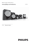
OUTER
1)Remove 10 screws A and 10 screws B/C as indicated to loosen the outer plate.
CD PART
REAR PLATE
A
C
B
OUTER PLATE
FRONT CAB.
BOTTOM PLATE
Dismantling of the CD part and Bottom plate and PCB Board
1)Remove 2 screws D as indicated to loosen the CD part.
2)Remove 2 screws E and 3 screws F as indicated to loosen the Bottom Plate.
4)Remove 2 screws G and 3 screws J as indicated to loosen the Main Board.
5)Remove 3 screws H and 4 screws K as indicated to loosen the Amp Board.
6)Remove 6 screws L as indicated to loosen the Smps power Board.
7)Remove 10 screws M as indicated to loosen the Display Board.
I
D
E
G
H
F
M
K
L
J
6-2
PCB LAYOUT - MAIN BOARD
6-2
7-1
CIRCUIT DIAGRAM - DISPLAY BOARD
7-1
7-2
PCB LAYOUT - DISPLAY BOARD
7-2
8-1
8-1
CIRCUIT DIAGRAM - CD BOARD
GPIO193 GPIO194 GPIO195
44
R563
4k7
LIMIT
C577
C576
47P
CLOSE_DET
(Original 3CD0_DET) BT_LED_CT
OPEN_DET
5
43
47P
42
6
DAC_MCK
40
(Original 3CD1_DET) AUX/LINE_SET
DATOUT_B
15
C514
100n
C573
CD-MUTE
0R
R4
Q523
AO3401A
CD+8V
C578
D501
IN4148
10R
R582
D502
IN4148
R526
C521
C522
47u/50v
100n
100k
R584
2K2
R528
10k
16
15
14
13
DOOR_CLOSE
12
DOOR_OPEN
11
10
9
+
C565
104
VCC
OE
STORBE
DATA
G4
CP
G5
G0
G6
G1
G7
G2
QS1
G3
QS2
GND
1
4094-DATA
2
REC_PWR
17
18
19
20
21
3
4
R538
1K
5
RESET
CD-MUTE
6
7
CD-PWR
8
IC505
74HC4094
2
1
CD-PWR
Q522
BC817-25
3
TO CON2
22UH
L902
3
CD+VCC
R548
2R2 1/6W
R547
2R2 1/6W
100P
C569
CON551
NC
2PIN-2.0
DOOR_CLOSE
3
4
GND
OPEN_DET
5
CL
104P
C527
1
2
C526
470u/16v
+3.3V
5P2.0
1
100P
C570
C572
DOOR_OPEN
R577
CLOSE_DET
NC
R5
0R
OPEN_DET
C580
C575
100P
100P
R541
10K
10K
R521
100P
C571
100P
M+
M-
CN506
C529
C530
470U/16V
104P
3V3
2
2SB772
Q502
R519
4K3
10K
R516
R3
VINFC
1
2
3
TRB_1
REGO2
VINSL+
4
FWD
REG01
5
6
100R
100R
R572
BT_LED_CT
1V8
220u/16
100R
R524
WORKING=1
MUTE=0
104P
C537
28
MUTE
27
C525
26
BIAS
VINTK
25
24
TRB_2
23
VINLD
OPOUT
29
22
7
REV
GND
VCC1
8
1V8
C523
30
R517
12K
AUX/LINE_SET
0R
R588
4094-CP
4094-OE
104
100R
100P
+3.3V
+3.3V
22
CD_MCK
23
CD_DIN_OUT
24
100n
25
CD_BUSY
26
CD_SUBSYQ
27
100n
R6
47u/50v
AM5888S
R570
21
20
19
VOTR+
VTOR9
10
11
VOSL+
VOSL12
VOFC-
VOFC+
14
C539
472P
100P
13
C574
GND
GND
VCTL
OPIN
VCC2
17
16
15
18
VOLD-
VOLD+
VOTK-
VOTK+
R522
18K
IC502
10K
6
R539
1
5
LIMIT
GND
3
4
+3.3V
LIMIT
2
3
SL-
4
SL+
1
5
SP-
2
SP+
6
CN505
6P2.0MM/90C
C538
104P
47U/50V
3K9
R520
16
CD-16M
1
C513
100u/16v
330p
C512
9
33
+3.3V
0R
DCK_B
LRCLK_B
34
TO MCU PCB
2K2
10
4k7
11
R557
12
4k7
4k7
13
R555
R556
35
14
37
36
DAC_LRCK
DAC_DATA
R589
DAC_DATA1
FFC28PIN-1.25
39
38
CON589
8
DAC_BCK
7
41
RESET
0R
1
CD-R
15P
FWT6600/9200 ADD R3,R4
R527
3
2
C516
TO MAIN PCB
4
CD-L
5
5
C579
100P
C568
CD+VCC
6
CD+8V
CD-16M
220R
6
CD-L
28
3V3
R583
C517
15P
3U3/50v
CD_RW
C561
C556
470k
100n
C551
C535
1
4k7
2K2
2
4k7
R562
R534
C534
470P
3K3
3
R561
R537
4
46
45
DGND0
XBUFO
47
32
31
17
48
2
50
51
52
53
49
XO
DGND2
TEST0
TEST1
54
LDACO
AGND1
DVDD2
55
57
56
VCDAC
RDACO
60
61
62
58
AVDD
AD-MONI0
AD-MONI1
ANA-MONI0
DVDD0
R514
R512
R513
C509
R515
100n
NC
C525A
100n
1M
36K
39K
22K
5K6
1V6
63
CLVOUT
0R
RESET
16
DOUTA
CLK&
15
100n
SDOUT
DVDD
R598
C524
LRCK_OUT
330p
R510
1K
DCK_OUT
TDOUT
C555
16 F-
VDD_CORE1
FDOUT
30
14
FCO
29
13
DFDIN
CLK
0.22U/50v
DFLRCK_IN
DGND
12
C505
R509 4K7
15 T-
BU9543
ASY
PCO
VDD_CORE
11
28
10
100n
470R
27
R511
WFCK
3U3/50v
C504
DFDCK_IN
SUBCK
Q501
DFSCK_IN
LD
26
14 T+
1
PD
470k
13 F+
8
9
C506
FLAG0
DGND1
R560
OR
R501
R508
4R7
11 VR
FLAG1
IC501
F
R558
470k
BC807-25
10 LD
AGND
E
25
6
24
5
SUBDATA
1n8
7
9 GND
12 PD
C508
1n8
FLAG2
SUBSYQ
C507
FLAG3
VBIAC
23
33K
ANA-MONI1
64
33K
R507
RF
EQO
R506
8 F
BD
22
16
7 C
XI
R559
15
4
BUBY
14
3
33K
R/W
13
33K
R505
21
12
33K
R504
6 B
DIN/OUT
11
R503
5 A
2K2
220R
R532
DVDD1
20
9
10
4 D
R531
R530
C515
AC
19
8
2
AVDD1
MCK
7
1
C503
100u/10v
6
33K
3
CN501
16P1.0MM/90C
5
R502
3 E
2
3
4
C510
100n
1V6
2 VCC
1n
2
1 VC
C502
1
C501
100u/16v
18
TO PICK UP
C552
100n
680P
59
C518
C511
C531
470P
X501 16.9344MHz
L501
100n
22UH
T1 T1 T1
4
470P
CD-R
C533
470P
3
100u/16v
C519
R536
3K3
3U3/50v
CON521
6P2.0MM/90C
C532
C536
2
100n
C520
2K2
1
R535
2K2
R533
This GND
must be
use AGND
2
T1
J12
1
T2 J9
8-2
PCB LAYOUT - CD BOARD
8-2
9-1
CIRCUIT DIAGRAM - MCU BOARD
9-1
9-2
PCB LAYOUT - MCU BOARD
9-2
10-1
10-1
CIRCUIT DIAGRAM - AMP BOARD
R7162
TO SMPS PB
OSC1
R7164
0R
CN701
VSSP1
R750
10R
-VCC
C767
100N
1N4002 D702
1N4002 D701
102
220k
C768
R755
R752
22R
VSSP1 17
VDDP1 14
350W
7
6
MODE
+VCC
DCOFFSET
220P
C762
VDDP1
VSSP1
220P
C761
VDDP1
104
C759
+
8 OHM
21
OUT2
15N
FRONT-L
1N4002 D704
D703
+VCC
102
220k
-VCC
100N
DCOFFSET
VSSP1
1N4002
C770
R754
22R
C769
10R
R751
C764
C763
C765
680N
220P
C754
104
VSSP1
VDDP1
R753
20 VSSP2
VDDP2
23
C7228 C752
104P 104P
104
C753
102
SPK1B
L702
VDDP1 220P
47PF
22
39K R719
+40V
VDDA1
VSSA1
15UH
C755
C8289
220N
473
C749
19 NC
13 PROT
1
18 STAB1
BOOT2
C748
C8288
102
1N
C740
47K
OSC
10
SGND
IN2+
IN2-
SPK1A
L701
15UH
C751
7
DIAG1
OUT1 16
TDA8954TH
P37
P36
+
P35
P34
C728
100N
100UF/25V
100N
C727
C726
C725
100UF/25V
C72841N
C72851N
C72781N
1N
C7282 1N
C72831N
C7280 1N
C7281 1N
C7279
+
C766
680N
15N
C756
15
BOOT1
IN1-
24 VSSD
4
BC857
R740
3
LIN
DIAG2 12
6
5
4
4
5
C757
OSCREF
C750
224
2
Q701
47K
GND
2
11
R741
RIN
P13
P14
MODE1
OSC
100P
NC
8
9
R744
474
5.6K
VSSA1
R739
Y7011
P11
IN1+
C746
R748
220
6.8K
600KHZ
1N
C738
47K
R736
+12V
5
9
R746
R742
C739
10K
DIG-CLK
P12
8
R749
56K
VSSA1
1N
1K
474
100P
102
C734
7
AMP-ON
P9
P10
CN702
10
11
13
3
2
C737
R735
1K
5.6K
VSSA
R734
R738
104
104P
C744
C747
330PF
C745
R747
220
3 VDDA
C736
100N
C735
10K
R733
22UF/50V
1K8
222
222
10K
C730
C731
10P
RIN
BC847
33PF
P8
6
5V6
1M
R737
-12V
C8929
GND
C758
R745
Z702
C7263
100P
R7154
Q702
1
DCOFFSET-CTL
P7
100N
10
9
SUB-ON/OFF-CTL
P6
8
10Px2.0x180C
C729
NC
C7227
U701
C743
47K
74CTO4
22UF/100V
C760
104P
+
1N
R7157
12
14
L722
220
R7156
1K8
30K
FB1K8
R731
L721
P5
C742
Y702
700KHZ
FB1K8
TO MAIN PB
1
100P
U706
+12V
-40V
P40
C741
0R
DIG-CLK
R702
P39
P4
R732
P26
P27
P28
P29
P30
P31
P32
P33
30K
7PINS 3.96x180C
P2
OSC
+40V
P1
R7163
R701
NC
P38
C720
R726
0R
1K5
47K
R7167
C8931
104
1K
BC847
R7161
C8930
10U/16v
1K
VSSA5
R7160
10R
C7241
-VCC
+VCC
DCOFFSET
220P
C791
VSSP2
VDDP2
VSSP2
+
220P
C787
C796
10R
R761
100N
1N4002 D706
1N4002 D705
C797
R766
220k
22
+VCC
104
350W
FRONT-R
C7287
D707
1N4002
1N4002 D708
104
C7286
C799
220k
100N
102
-VCC
VSSP2
VDDP2
DCOFFSET
C793
220P
220P
C792
C782
104
C798
22R
10R
C7230 C781
104P 104P
R764
R763
SPK2B
L704
R762
20 VSSP2
13 PROT
19 NC
24 VSSD
18 STAB1
102
R765
22R
VSSP1 17
VDDP1 14
MODE
6
7
DIAG2 12
OSC
VSSA2
Q707
R711
102
Q708
100MHZ 80R
VDDA2
BC857
1K
15UH
C783
C794
680N
C780
104
R7165
VSSA2
VSSA4
VSSP5
R7159
10R
L720
C790
OSC1
474
C779 47PF
C774
5.6K
C778
224
R759
102
220
R710
NTC-47K
100MHZ 80R
VSSP4
R757
R7166 470K
L719
R7158
VSSA3
22K
10R
IN2-
C777
R709
100MHZ 80R
4
R760
56K
8 OHM
21
15N
473
474
OUT2
BOOT2
C8291
C773
SGND
1
5.6K
100P
SPK2A
L703
15UH
IN2+
C776
C772
OUT1 16
TDA8954TH
220N
R758
220
C775
5
R756
C795
680N
15N
C784
15
BOOT1
IN1-
3 VDDA
100P
104
OSCREF
VSSA
2
C771
LIN
DIAG1
10
11
330PF
VSSP3
L718
VSSA2
improved PS auto protect(standby)
VSSA2
100MHZ 80R
9
C716
100N
C8290
VSSP2
+
8 IN1+
+40V
10R
104P
BC847
C715
R7155
+12V
L717
R714 47K
VSSA1
C786
Q706
BC847
DCOFFSET
L727
100MHZ 80R
153
C7244
C7243
C7242
+
47K
+40V
R712 68k
VSSP1
100UF/25V
10R
C7229
C785
(TO MCU PWR_DET)
Q705
GND
104P
U702
-40V
R708
C724
10UF/50V
DCOFFSET-CTL
R713 68k
L716
22UF/100V
C789
VSSP2
C7261
473
C7262
220N
C7258
C7259
220N
220N
+
C7255
15N
C7274
15N
C7272
C7254
+
VDDP2
C7260
473
R730
0R
VDDP2
C7257
473
R729
0R
MODE2
C7256
473
10UF/50V
1K
104
C7253
15N
R725
P43
-VCC
1K
MODE5
C708
C710
C712
C706
C714
470UF/50V470UF/50V 470UF/50V 470UF/50V 470UF/50V
100MHZ 80R
L726
R728
0R
10UF/50V
1K
C713
470UF/50V
220N
+
15N
C7270
15N
C7266
15N
C7268
+
P17
C723
+
220N
15N
C7265
C704
100N
100MHZ 80R
C722
MODE3
R723
+
C707
C711
C709
470UF/50V 470UF/50V 470UF/50V
+
+
L728
100MHZ 80R
MODE2
+
C705
470UF/50V
15N
C7276
C7239
100N
470UF/50V
C7240
C702
1K
R724
P41
2
LT7
2200UF/50V
5V6
VDDP1
473
+
+
C7275
C7273
15N
15N
C7271
C7269
15N
C7267
C7277
15N
C7237
470UF/50V
15N
C7264
C703
C7238
100N
+
R722
SPK2A
MODE4
10R
+
100MHZ 80R
100N
15N
+
+
C701
Z701
R7151
P16
SPK2B
R707
L725
2200UF/50V
1K
VDDP2
100MHZ 80R
VDDP2
R721
23
L715
VDDA2
10R
+
BC847
1K
P3
P15
J5M
SPK1B
R727
0R
+
100MHZ 80R
10UF/50V
VDDA1
+
1
+
SP01
J703
SPK1A
C721
MODE1
C718
L714
L723
-40V
+
C717
+VCC
R706
100MHZ 80R
100MHZ 80R
+40V
VDDP3
R718
Q704
L724
P42
6TS:6TS
3
4
VDDA3
10R
power on=4v8
C719
100MHZ 80R
L713
1K
power on=0.3v
R716
AMP-ON
1UF/50V
VDDP4
R705
22UF/50V
VDDA4
10R
100MHZ 80R
R717
standy=2v8
R715 4K7
R704
L712
47K
BC847
VDDP5
153
153
153
VDDA5
10R
10UF/25V
R703
100MHZ 80R
L711
standy=0.9v
R720
Q703
+
10UF/50V
10-2
10-2
10R
104P
R783
GND
D710
1N4002
102
1N4002 D709
R788
R787
22R
17
VSSP1
14
MODE
VDDP1
6
300W
C7245
153
C7248
C7247
C7246
153
153
153
-VCC
C7170
102
1N4002 D714
R7120
C7171
220k
22R
1N4002 D713
100N
300W
1N4002 D716
C7173
102
1N4002 D715
R7108
C7172
R7106
10R
220P
C7167
220P
220k
22R R7107
P23
J5M
P24
P25
104P
R7144
C7185
39K
100P
5.6K
R7142
C7189
470N
C7252
C7251
C7249
C7250
153
153
153
153
-VCC
150W
+
D717
1N4002 D718
102
1N4002
C7224
100N
22R
220k
R7149
VSSP1 17
MODE
6
VDDP1 14
150W
4 OHM
+
D719
1N4002
102
1N4002 D720
-
C7226
R7148
220k
22R R7147
C7225
C7221
680N
100N
R7146
10R
473
C7192
SPK6A
L710
SPK6B
SPK6B
+VCC
470N
15UH
-VCC
C7188
5.6K
15N
22
DCOFFSET
R7141
220
C7193
R7138
7
C7200
220N
470N C7187
VSSA5
5.6K
C8296
R7140
220
102
R7137
330PF
GND
C7191
GND
21
VSSP5
IN2-
1
4
OUT2
BOOT2
C7220
R7134
82K
OSC
SGND
IN2+
220P
5
C7209
2
39K
220P
C7181
NC
NC
NoiseR7143
VDDP5
100P
SPK5B
L709
15UH
C7199
C7184
100N
15N
4 OHM
TDA8954TH
104
330PF
C7182
Noise
11
OSCREF
20 VSSP2
NC
VSSA5
C7201
OUT1 16
23 VDDP2
C7190
15
BOOT1
IN1-
VSSP5
470N
VDDP5
5.6K
IN1+
19 NC
220
9
47PF
C7186
+12V
683
R7130
Noise
R7139
C7195
100N
R7136
C7222
680N
C7198
104P
C7177
153
8
7
U709-B
C7236
104P
82K
+
104P
C7196
104
R7127
C7176
-
13 PROT
683
6
5
C7180
-12V
C7175
6K8
18 STAB1
24K
U709-A
D4556
R7133
C7179
C7194
224
R7131
12
220
C8297
153 Frequency Response
10P
1
4
DIAG2
+
102
NC
-
3
VSSA5
R7124
2
10P
3 VDDA
24K
6K8
C7183
24 VSSD
1K5
R7125
C7174
1K5
4K7
VDDA5
R7123
R7129
DIAG1
LIN
C7178
VSSA
4K7
R7132
GND
1K5
R7126
C7203
10
R7128
GND
R7122
R7135
8
1K5
C7223
104
C7202
R7121
R7150
GND
C7235
U705
Noise
Noise
+VCC
10R R7145
104
DCOFFSET
220P
VSSP5
VDDP5
C7207
220P
C7206
VSSP5
VDDP5
+
200HZ-150HZ -3DB
C7204
MODE5
OSC
C7205
22UF/100V
1
2
3
4
5
RL-CH
20 VSSP2
23 VDDP2
C7166
C7154 47PF
C7234 C7156
104P 104P
19 NC
13 PROT
18 STAB1
24 VSSD
C7152
224
VSSA
3 VDDA
SPK6A
J705
SPK6B
RIN
R-SUB
10R
17
14
VSSP1
OSC
MODE
VDDP1
6
7
DIAG2 12
C7153
100N
SP03
P22
SPK5A
SPK5B
RR-CH
474
C7148
GND
+VCC
5.6K
R7101
C7168
680N
-VCC
220
R7100
SPK4B
L708
DCOFFSET
NC
15UH
VSSP4
R798
15N
C7157
C7146
100N
C7158
VDDP4
+12V
224
21
22
104
C7144
8 OHM
VSSP4
224
C7155
104
C7143
224
VDDP4
C7142
47K
102
R794
NC
VSSA4
R792
100N
473
220
C7140
C7149
474
R7102
5.6K
R799
C8295
U708-B
-12V
C7138
100N
VDDA4
+
7
220N
+
D4556
-
VSSA4
1K
1
153
5
C8294
6K8
102
12K
6
U708-A
C7151
10K
C7145
1
4
OUT2
IN2-
C7150
+
R796
330PF
-
3
10K
4
8k2
2
10UF/50V
R797
R7103
100P
R790
R795
R793
4
SPK4A
L707
BOOT2
330PF
C7139
SGND
IN2+
56K
C7141
16
15UH
R7152
8
8K2
OUT1
TDA8954TH
C7147
+
R789
DIAG1
10
5
15N
C7159
15
OSCREF
2
LIN
104
C7160
BOOT1
IN1-
9
R7105
C7161
104P
11
3
5
GND
C7169
680N
R7109
U704
VSSA4
+VCC
DCOFFSET
220P
C7165
220P
C7164
VSSP4
VSSP4
VDDP4
VDDP4
+
104P
C7233
30HZand 120HZ -3DB
2
P21
1K
R7104
8 IN1+
1
P20
SPK4A
SPK4B
22UF/100V
C7163
104
C7162
MODE4
OSC1
SUB-ON/OFF-CTL
C7137
1UF/50V
P18
P19
J5M
SPK3B
18K
SP02
J704
SPK3A
5.6K
R791
L-SUB
1N4002 D712
1N4002
100N
D711
C7136
C7135
R786
22R
R784
10R
220P
C7129
220P
C7232 C7119
104P 104P
220k
20 VSSP2
23 VDDP2
19 NC
47PF
102
7
OSC
13 PROT
18 STAB1
24 VSSD
VSSA
3 VDDA
R785
+VCC
474
R780
GND
-VCC
C7112
DCOFFSET
220
R778
C7130
C7110
330PF
NC
C7120
R776
SPK3B
VSSP3
C7109
100N
C7131
680N
104
224
L706
VDDP3
224
15UH
VSSP3
C7106
224
VDDP3
C7105
47K
NC
VSSA3
R771
R769
100N
+12V
8k2
C7103
C7107
15N
22
C7118
104
-12V
C7101
100N
C7117
7
U707-B
VSSA3
+
473
-
5
102
6
VDDA3
U707-A
D4556
C8293 C7116
224
153
C7115
1
C7108
1
4
1K
4
C8292
6K8
474
C7114
12K
220
102
+
10K
10K
R774
220N
-
3
10UF/50V
R773
+
R7153
R772
R770
C7113
100P
2
C7104
330PF
C7102
8
8K2
8 OHM
C7121
BOOT2
IN2-
SPK3A
21
OUT2
IN2+
C7111
R779
5.6K
R781
+
C7100
1UF/50V
R777
56K
L705
15UH
SGND
5
R775
18K
OUT1 16
TDA8954TH
RIN
R768
C7132
680N
15N
C7122
15
OSCREF
11
2
R767
104
C7123
BOOT1
IN1-
9
VSSA3
DIAG2 12
DIAG1
10
104P
C7134
100N
C7124
8 IN1+
-VCC
C7133
C7231
U703
220k
1K
R782
+VCC
DCOFFSET
220P
C7128
VSSP3
220P
VSSP3
C7127 VDDP3
22UF/100V
C7126
+
SUB-ON/OFF-CTL
104
C7125
VDDP3
MODE3
OSC
CIRCUIT DIAGRAM - AMP BOARD
10-3
PCB LAYOUT - AMP BOARD
10-3
11-1
CIRCUIT DIAGRAM - TUNER BOARD
11-1
11-2
PCB LAYOUT - TUNER BOARD
11-2
12-1
EXPLODED VIEW
12-1