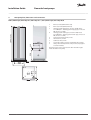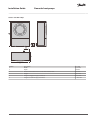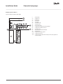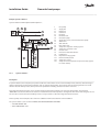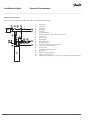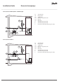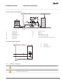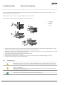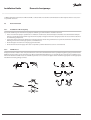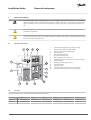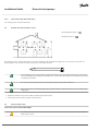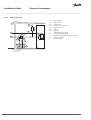
1
MAKING MODERN LIVING POSSIBLE
Installation Guide
Domestic heat pumps
DHP-A Opti
DHP-C
DHP-C Opti
DHP-C Opti W/W
DHP-H
DHP-H Opti
DHP-H Opti Pro/Opti Pro+
DHP-L
DHP-L Opti
DHP-L Opti Pro/Opti Pro+
www.heating.danfoss.com
Danfoss A/S is not liable or bound by warranty if these
instructions are not adhered to during installation or service.
The English language is used for the original instructions.
Other languages are a translation of the original instructions.
(Directive 2006/42/EC)
© Copyright Danfoss A/S
Installation Guide
Domestic heat pumps
1
About documents and decals . . . . . . . . . . . . . . . . . . . . . . . . . . . . . . . . . . . . . . . . . . . . . . . . . . . . . . . .
1.1 Introduction . . . . . . . . . . . . . . . . . . . . . . . . . . . . . . . . . . . . . . . . . . . . . . . . . . . . . . . . . . . . . . . .
1.2 Symbols in documents . . . . . . . . . . . . . . . . . . . . . . . . . . . . . . . . . . . . . . . . . . . . . . . . . . . . . . . . . .
1.3 Symbols on decals . . . . . . . . . . . . . . . . . . . . . . . . . . . . . . . . . . . . . . . . . . . . . . . . . . . . . . . . . . . .
4
4
4
4
2
Important information/Safety regulation . . . . . . . . . . . . . . . . . . . . . . . . . . . . . . . . . . . . . . . . . . . . . . . .
2.1 General safety precautions . . . . . . . . . . . . . . . . . . . . . . . . . . . . . . . . . . . . . . . . . . . . . . . . . . . . . . .
2.2 Electrical connection . . . . . . . . . . . . . . . . . . . . . . . . . . . . . . . . . . . . . . . . . . . . . . . . . . . . . . . . . . .
2.3 Water quality . . . . . . . . . . . . . . . . . . . . . . . . . . . . . . . . . . . . . . . . . . . . . . . . . . . . . . . . . . . . . . . .
2.4 Commissioning . . . . . . . . . . . . . . . . . . . . . . . . . . . . . . . . . . . . . . . . . . . . . . . . . . . . . . . . . . . . . .
6
6
8
8
9
3
Transport, unpacking and setting-up . . . . . . . . . . . . . . . . . . . . . . . . . . . . . . . . . . . . . . . . . . . . . . . . . . .
3.1 Transporting the heat pump . . . . . . . . . . . . . . . . . . . . . . . . . . . . . . . . . . . . . . . . . . . . . . . . . . . . . .
3.2 Unpacking . . . . . . . . . . . . . . . . . . . . . . . . . . . . . . . . . . . . . . . . . . . . . . . . . . . . . . . . . . . . . . . . .
3.3 Setting-up the heat pump . . . . . . . . . . . . . . . . . . . . . . . . . . . . . . . . . . . . . . . . . . . . . . . . . . . . . . .
3.4 Setting-up the outdoor unit . . . . . . . . . . . . . . . . . . . . . . . . . . . . . . . . . . . . . . . . . . . . . . . . . . . . . .
10
10
10
11
13
4
Heat pump data, dimensions and connections . . . . . . . . . . . . . . . . . . . . . . . . . . . . . . . . . . . . . . . . . . . .
17
5
Piping installation . . . . . . . . . . . . . . . . . . . . . . . . . . . . . . . . . . . . . . . . . . . . . . . . . . . . . . . . . . . . . . . .
5.1 Safety valves . . . . . . . . . . . . . . . . . . . . . . . . . . . . . . . . . . . . . . . . . . . . . . . . . . . . . . . . . . . . . . . .
5.2 Connection heating and hot water . . . . . . . . . . . . . . . . . . . . . . . . . . . . . . . . . . . . . . . . . . . . . . . . . .
5.3 Connection brine . . . . . . . . . . . . . . . . . . . . . . . . . . . . . . . . . . . . . . . . . . . . . . . . . . . . . . . . . . . . .
5.4 Maximum length of collectors . . . . . . . . . . . . . . . . . . . . . . . . . . . . . . . . . . . . . . . . . . . . . . . . . . . . .
5.5 Noise information . . . . . . . . . . . . . . . . . . . . . . . . . . . . . . . . . . . . . . . . . . . . . . . . . . . . . . . . . . . . .
22
23
23
31
36
38
6
Electrical Installation . . . . . . . . . . . . . . . . . . . . . . . . . . . . . . . . . . . . . . . . . . . . . . . . . . . . . . . . . . . . . .
6.1 Electrical components . . . . . . . . . . . . . . . . . . . . . . . . . . . . . . . . . . . . . . . . . . . . . . . . . . . . . . . . . .
6.2 Fuse size . . . . . . . . . . . . . . . . . . . . . . . . . . . . . . . . . . . . . . . . . . . . . . . . . . . . . . . . . . . . . . . . . . .
6.3 Connecting external supply voltage . . . . . . . . . . . . . . . . . . . . . . . . . . . . . . . . . . . . . . . . . . . . . . . . .
6.4 Position and connect outdoor sensors . . . . . . . . . . . . . . . . . . . . . . . . . . . . . . . . . . . . . . . . . . . . . . . .
6.5 Connect outdoor unit . . . . . . . . . . . . . . . . . . . . . . . . . . . . . . . . . . . . . . . . . . . . . . . . . . . . . . . . . .
6.6 Connect temperature sensor hot water . . . . . . . . . . . . . . . . . . . . . . . . . . . . . . . . . . . . . . . . . . . . . . .
6.7 Selection of system solution and connection of external aux. heater . . . . . . . . . . . . . . . . . . . . . . . . . . . .
39
39
39
40
42
42
43
44
7
Menu information . . . . . . . . . . . . . . . . . . . . . . . . . . . . . . . . . . . . . . . . . . . . . . . . . . . . . . . . . . . . . . . .
47
8
INFORMATION menu . . . . . . . . . . . . . . . . . . . . . . . . . . . . . . . . . . . . . . . . . . . . . . . . . . . . . . . . . . . . . .
8.1 Sub-menu OPERAT. . . . . . . . . . . . . . . . . . . . . . . . . . . . . . . . . . . . . . . . . . . . . . . . . . . . . . . . . . . . .
8.2 Sub-menu HEAT CURVE . . . . . . . . . . . . . . . . . . . . . . . . . . . . . . . . . . . . . . . . . . . . . . . . . . . . . . . . .
8.3 Sub-menu HEAT CURVE 2 . . . . . . . . . . . . . . . . . . . . . . . . . . . . . . . . . . . . . . . . . . . . . . . . . . . . . . . .
8.4 Sub-menu TEMPERATURE . . . . . . . . . . . . . . . . . . . . . . . . . . . . . . . . . . . . . . . . . . . . . . . . . . . . . . . .
8.5 Sub-menu OPERAT.TIME . . . . . . . . . . . . . . . . . . . . . . . . . . . . . . . . . . . . . . . . . . . . . . . . . . . . . . . . .
8.6 Sub-menu DEFROST . . . . . . . . . . . . . . . . . . . . . . . . . . . . . . . . . . . . . . . . . . . . . . . . . . . . . . . . . . .
8.7 Sub-menu LANGUAGE . . . . . . . . . . . . . . . . . . . . . . . . . . . . . . . . . . . . . . . . . . . . . . . . . . . . . . . . . .
48
48
48
49
49
50
50
51
9
SERVICE menu . . . . . . . . . . . . . . . . . . . . . . . . . . . . . . . . . . . . . . . . . . . . . . . . . . . . . . . . . . . . . . . . . .
9.1 Sub-menu HOT WATER . . . . . . . . . . . . . . . . . . . . . . . . . . . . . . . . . . . . . . . . . . . . . . . . . . . . . . . . .
9.2 Sub-menu HEAT PUMP . . . . . . . . . . . . . . . . . . . . . . . . . . . . . . . . . . . . . . . . . . . . . . . . . . . . . . . . . .
9.3 Sub-menu AUX. HEATER . . . . . . . . . . . . . . . . . . . . . . . . . . . . . . . . . . . . . . . . . . . . . . . . . . . . . . . . .
9.4 Sub-menu MANUAL TEST . . . . . . . . . . . . . . . . . . . . . . . . . . . . . . . . . . . . . . . . . . . . . . . . . . . . . . . .
9.5 Sub-menu INSTALLATION . . . . . . . . . . . . . . . . . . . . . . . . . . . . . . . . . . . . . . . . . . . . . . . . . . . . . . . .
9.6 Sub-menu DEFROST . . . . . . . . . . . . . . . . . . . . . . . . . . . . . . . . . . . . . . . . . . . . . . . . . . . . . . . . . . .
9.7 Sub menu OPTIMUM . . . . . . . . . . . . . . . . . . . . . . . . . . . . . . . . . . . . . . . . . . . . . . . . . . . . . . . . . . .
9.8 Sub-menu HGW . . . . . . . . . . . . . . . . . . . . . . . . . . . . . . . . . . . . . . . . . . . . . . . . . . . . . . . . . . . . . .
52
52
52
53
54
55
58
58
59
10
Commissioning . . . . . . . . . . . . . . . . . . . . . . . . . . . . . . . . . . . . . . . . . . . . . . . . . . . . . . . . . . . . . . . . . .
10.1 Checking the pipes and electrical installation . . . . . . . . . . . . . . . . . . . . . . . . . . . . . . . . . . . . . . . . . . .
10.2 Configuration of control system . . . . . . . . . . . . . . . . . . . . . . . . . . . . . . . . . . . . . . . . . . . . . . . . . . . .
10.3 Filling and bleeding the water heater and heating system . . . . . . . . . . . . . . . . . . . . . . . . . . . . . . . . . . .
10.4 Filling and bleeding the brine system . . . . . . . . . . . . . . . . . . . . . . . . . . . . . . . . . . . . . . . . . . . . . . . .
10.5 Manual test . . . . . . . . . . . . . . . . . . . . . . . . . . . . . . . . . . . . . . . . . . . . . . . . . . . . . . . . . . . . . . . . .
10.6 Commissioning . . . . . . . . . . . . . . . . . . . . . . . . . . . . . . . . . . . . . . . . . . . . . . . . . . . . . . . . . . . . . .
10.7 Installation protocol . . . . . . . . . . . . . . . . . . . . . . . . . . . . . . . . . . . . . . . . . . . . . . . . . . . . . . . . . . .
10.8 Customer information . . . . . . . . . . . . . . . . . . . . . . . . . . . . . . . . . . . . . . . . . . . . . . . . . . . . . . . . . .
60
60
60
61
62
68
71
72
72
Danfoss Heating Solutions
VMGFQ202
3
Installation Guide
1
About documents and decals
1.1
Introduction
Domestic heat pumps
The following documents are available for this product:
▪ The Wiring diagrams that contain the wiring diagram for the heat pump intended for fault tracing and service. The Wiring diagrams
are available for download as below.
▪ The User manual must handed over and gone through with the end customer. Supplied with the heat pump on delivery.
▪ Country specific instructions and forms are available where relevant. Supplied with the heat pump on delivery.
▪ Self-adhesive decals with translation text. Must be placed on the manufacturing plate in conjunction with installation. Supplied
with the heat pump on delivery.
The Service instructions and Wiring diagrams are available for download here:
www.documentation.heatpump.danfoss.com
1.2
Symbols in documents
The instructions contain different warning symbols, which, together with text, indicate to the user that there are risks involved with actions to be taken.
The symbols are displayed to the left of the text and three different symbols are used to indicate the degree of danger:
Indicates an immediate danger that leads to fatal or serious injury if necessary measures are not taken.
Risk of personal injury!
Indicates a possible danger that can lead to fatal or serious injury if necessary measures are not taken.
Risk of installation damage.
Indicates a possible hazard that can lead to item damage if necessary measures are not taken.
A fourth symbol is used to give practical information or tips on how to perform a procedure.
N
1.3
Information regarding making the handling of the installation easier or a possible operational technical disadvantage.
Symbols on decals
The following symbols can occur on decals on the different parts of the heat pump. Which symbols are used depends on the heat pump
model.
4
VMGFQ202
Danfoss Heating Solutions
Installation Guide
1.3.1
!
!
Domestic heat pumps
General
Warning, danger!
Warning, hot surfaces!
Read the documentation provided.
Warning, moving parts!
Read the documentation provided.
Warning, risk of crushing injury!
Warning, hazardous electrical voltage!
1.3.2
3
50
54
55
71
304
353
362
363
365
366
1.3.3
Electrical components
Outdoor unit
Outdoor sensor
Hot water sensor
Hot water top sensor
Flow guard
Circulation pump
Drip tray
Shunt valve
Exchange valve hot water
Supply line sensor
406 Room sensor
or
62
408 EVU
417 Defrost sensor
Explanation
Component, ordinary delivery according to proposed system solutions
Component, accessorie according to proposed system solutions
Return line sensor
Pipe connections
Tap water
Heating system
Brine system
Defrosting tank
Expansion tank with safety valve, brine
Air bleeding
Temperature and pressure relief valve
Outdoor unit
Water heater
Danfoss Heating Solutions
VMGFQ202
5
Installation Guide
Domestic heat pumps
2
Important information/Safety regulation
2.1
General safety precautions
Risk of personal injury! Children are not permitted to play with the product.
As the water temperature in DHP-H Opti Pro/DHP-H Opti Pro + and DHP-L Opti Pro/DHP-L Opti Pro + becomes hot (up to 95°C), a mixer valve must be installed between the cold water and hot water pipes to ensure
a lower domestic hot water temperature.
Alternatively the maximum hot water temperature must be reduced in the Service menu.
Danfoss SP (1-phase) heat pumps have a factory installed safety valve for temperature and pressure, (10 bar
90-95°C), in accordance with the requirements in Great Britain. This valve is located in the water tank and may
not be used for any purpose other than connecting the outlet pipe. Also note that for heat pump DHP-H Opti
Pro SP and DHP-L Opti Pro SP it is imperative that the hot water temperature is changed from default setting
95°C to 85°C.
The heat pump must be installed by authorised installation engineers and the installation must follow the
applicable local rules and regulations as well as these installation instructions.
This product is not intended for persons (including children) with reduced physical, sensory or psychological
capacity, or who do not have knowledge or experience, unless supervised or they have received instructions
on how the apparatus functions from a safety qualified person.
The heat pump must be located in a frost-free environment!
The heat pump must be placed in an area with a floor drain.
The heat pump must be located on a stable base. The floor must be able to support the gross weight of the
heat pump with filled hot water tank (see Technical data).
To prevent leaks, ensure that there are no stresses in the connecting pipes!
It is important that the heating system is bled after installation.
Bleed valves must be installed where necessary.
The hot water tank must be equipped with an approved safety valve.
Heating systems with closed expansion tanks must also be supplied with approved pressure gauges and safety valves.
6
VMGFQ202
Danfoss Heating Solutions
Installation Guide
Domestic heat pumps
Cold and hot water pipes and overflow pipes from safety valves must be made of heat resistant and corrosion-resistant material, for example copper. The safety valve overflow pipes must have an open connection to
the drain and visibly flow into this in a frost-free environment.
The connecting pipe between the expansion tank and the safety valve must slope continuously upwards. A
continuous upwards slope means that the pipe must not slope downwards from the horizontal at any point.
When cooling it is important to limit the lowest flow line temperature to prevent condensation.
N
If there is any risk of groundwater infiltration at wall lead-ins for brine pipes, watertight grommets must be
used.
N
In addition to applicable local rules and regulations the installation should be carried out in a manner that
prevents vibrations from the heat pump being transmitted into the house causing noise.
2.2
Refrigerant
2.2.1
Refrigerant
Work on the refrigerant circuit must only be carried out by a certified engineer!
Although the heat pump cooling system (refrigerant circuit) is filled with a chlorine-free and environmentally-approved refrigerant that
will not affect the ozone layer, work on this system may only be carried out by authorized persons.
2.2.2
Fire risk
The refrigerant is not combustible or explosive in normal conditions.
2.2.3
Toxicity
In normal use and normal conditions the refrigerant has low toxicity. However, although the toxicity of the refrigerant is low, it can cause
injury (or be highly dangerous) in abnormal circumstances or where deliberately abused.
Risk of personal injury! Spaces in which heavy vapour can collect below the level of the air must be well ventilated.
Refrigerant vapour is heavier than air and, in enclosed spaces below the level of a door for example, and in the event of leakage, concentrations can arise with a resultant risk of suffocation due to a lack of oxygen.
Risk of personal injury! Refrigerant exposed to a naked flame creates a poisonous irritating gas. This gas can
be detected by its odour even at concentrations below its permitted levels. Evacuate the area until it has been
sufficiently ventilated.
Danfoss Heating Solutions
VMGFQ202
7
Installation Guide
2.2.4
Domestic heat pumps
Work on the refrigerant circuit
When repairing the refrigerant circuit, the refrigerant must not be released from the heat pump, it must treated in the appropriate way.
Draining and refilling must only be carried out using new refrigerant (for the amount and type of refrigerant see manufacturer’s plate)
through the service valves.
All warranties from Danfoss are void if, when filling with refrigerant other than Danfoss A/S specified refrigerant, if there has not been written notification that the new refrigerant is an approved replacement refrigerant
together with other remedies.
2.2.5
Scrapping
When the heat pump is to be scrapped the refrigerant must be extracted for disposal. Local rules and regulations related to the disposal of refrigerant must be followed.
2.3
Electrical connection
Hazardous electrical voltage! The terminal blocks are live and can be highly dangerous due to the risk of electric shock. All power supplies must be isolated before electrical installation is started. The heat pump is connected internally at the factory, for this reason electrical installation consists mainly of the connection of the
power supply.
Electrical installation may only be carried out by an authorized electrician and must follow applicable local
and national regulations.
The electrical installation must be carried out using permanently routed cables. It must be possible to isolate
the power supply using an all-pole circuit breaker with a minimum contact gap of 3 mm. (The maximum load
for externally connected units is 2A).
2.4
Water quality
A normal heating system always contains a certain amount of corrosion particulates (rust) and sludge products from calcium oxide. This comes from acid that is naturally occurring in the fresh water that the system is
filled with. It is not good practice to have to fill the heating system regularly which is why any leakage in the
heating system should be repaired immediately. Normal filling should occur only once or twice a year. The
water in the heating system should be as clean as possible, always position the dirt filter on the return line
from the heating system to the heat pump, as close to the heat pump as possible.
Hard water; Normally it is not a problem installing a heat pump in areas with hard water because the normal
operating temperature for the hot water does not exceed 60°C. In areas where there are exceptional prevailing conditions with the water one can install a softening filter, which softens the water, cleans any impurities
and prevents the build up of calcification.
8
VMGFQ202
Danfoss Heating Solutions
Installation Guide
2.5
Domestic heat pumps
Commissioning
The installation may only be commissioned if the heating system and brine system have been filled and bled.
Otherwise the circulation pumps can be damaged.
If the installation is only to be driven by the immersion heater during the installation, ensure that the heating
system is filled and the brine pump and compressor cannot be started. This is carried out by setting the operating mode to AUX. HEATER.
Danfoss Heating Solutions
VMGFQ202
9
Installation Guide
Domestic heat pumps
3
Transport, unpacking and setting-up
3.1
Transporting the heat pump
During transportation or lifting of the entire heat pump, the front panel must always be installed as it locks
the other panels construction.
The heat pump must always be transported and stored in a dry area. Secure the heat pump so that it cannot
tip over during transportation.
The heat pump must always be transported and stored standing and in a dry environment. If the heat pump is
laid on the incorrect side it may become seriously damaged as the oil in the compressor can run out in the
pressure pipe and therefore prevent normal function.
When transporting indoors to the installation location it may be necessary to place the heat pump on its back. The time that the heat
pump is transported on its back should be as short as possible. After the heat pump has been lifted up again it must stand upright for at
least an hour before commissioning.
3.2
Unpacking
3.2.1
Unpack the heat pump
1. Check that there is no transport damage.
2. Remove the packaging.
3.2.2
Delivery check
1. Check that the delivery contains the following components:
4-10 kW
1
12-13 kW
1
16-17 kW
1
1
1
1
1
1
1
1
1
1
Filling device DN252
5
2
1
5
2
1
5
2
-
Filling device DN322
-
-
1
Dirt strainer with shut off valve DN20 1
Dirt strainer with shut off valve DN25
Manual holder
1
Does not apply to DHP-C Opti W/W
1
-
-
1
1
1
1
1
Safety valve 9 bar ½"
1
Safety valve 1,5 bar ½" or 3 bar 1/2'' 1
Outdoor sensor
Expansion and bleed tank or Expansion vessel with
Rubber bellows for 22-28 mm hole
Rubber hose R20 L=550
Rubber hose R25 L=550
2
10
manometer2
Not included in DHP-C Opti W/W delivery
VMGFQ202
Danfoss Heating Solutions
Installation Guide
3.3
Setting-up the heat pump
3.3.1
Recommended location
Domestic heat pumps
To avoid condensation problems for the brine lines, as short a brine line as possible is recommended indoors.
The heat pump should be located on a stable floor, preferably made of concrete. When locating the heat pump on a wooden floor this
should be reinforced to take the weight of the heat pump including a filled water heater, see technical data for relevant heat pump. One
solution is to place a thick metal plate, at least 6mm, under the heat pump. The metal plate should cover several joists spreading the
weight of the heat pump over a larger area. If the heat pump is being installed in a newly-built house, this has normally been taken into
account during construction, and the joists where the heat pump will be located have been reinforced. Always check that this has been
carried out when installing into a newly-built house.
Avoid positioning the heat pump in a corner as the surrounding walls may amplify its noise. It is also important to adjust the heat pump
using the adjustable feet so that it is horizontal to the base.
3.3.2
Space requirement
The heat pump must not be enclosed as the temperature inside the cabinet becomes extremely high.
To facilitate the fitting, installation and subsequent testing and maintenance there must be sufficient free space around the heat pump
in accordance with the following dimensions:
Danfoss Heating Solutions
VMGFQ202
11
Installation Guide
Domestic heat pumps
300 mm
1620
300 mm
1905
300 mm
10 mm
600 mm
3.3.3
12
Setting up
N
The heat pump has feet that can be adjusted to compensate for irregularities in the surface on which it is
sitting. If the surface is so irregular that the feet cannot compensate for it, the installation engineer must remedy this.
N
It is recommended that the condensation drain is installed from the drip tray’s drain pipe by lying the heat
pump down. The drain pipe opens through a hole in the base plate and has a Ø10 mm hose connection.
N
If the heat pump has been laid down it is recommended that it stands upright for at least an hour before
commissioning.
VMGFQ202
Danfoss Heating Solutions
Installation Guide
3.3.4
Domestic heat pumps
Removing the front cover
Do not damage the electrical wiring for the display when the front cover
is removed!
1
2
1. Press against the front cover and turn the catch 90° degrees anti-clockwise to release the front
cover.
2. Tilt the front cover outwards.
3. Lift the front cover upwards to remove it from the heat pump.
3
3.4
Setting-up the outdoor unit
3.4.1
Recommended location
When positioning the outdoor unit, note the following:
When the outdoor unit is defrosting, water will drip straight down under the unit. The area around the outdoor unit must therefore be properly drained in order to take the water (approximately 6 litres per defrost).
The outdoor unit must be positioned on a secure base such as wooden sleepers, paving slabs or cast footings.
N
N
Danfoss Heating Solutions
The outdoor unit does not have to be positioned in any specific direction.
Position the outdoor unit to reduce noise disturbance in your own home as well as to any neighbours.
VMGFQ202
13
Installation Guide
3.4.2
Domestic heat pumps
Foundation for outdoor unit
1. Position the outdoor unit on a stable base that can take the total weight, see Technical data.
2. Secure all four mounting points on a stable base, for example a cast foundation.
1
4
8
5
a
7
100 mm
2
3
b
~900 mm
c
Measurements
1
2
3
4
5
6
7
8
6-12 kW
470 mm
480 mm
672 mm
190 mm
65 mm
~1,200 mm
~720 mm
Ø 65 mm
Position
a
b
c
Description
Drainage hole
Foundation
Gravel
6
Bolt size
6-12 kW
M12 (4x)
A driptray is installed with the purpose of gathering and draining away melt water during defrosting. Connect
a hose or pipe along with a heat trace cable between the outlet of the drip tray and a drain or a free draining
piece of ground. The heat cable must be connected to the terminal provided and is necessary to prevent ice
blockage.
Check with a spirit level that the outdoor unit is installed horizontally.
14
VMGFQ202
Danfoss Heating Solutions
Installation Guide
Domestic heat pumps
Incorrect positioning of the outdoor unit risks reduction of performance.
N
N
Remember that the outdoor unit must have a certain amount of space in order to function and for servicing.
Otherwise there is a risk that the air will recirculate from exhaust to intake. Avoid this by following the dimensions given below.
Space requirement
>500 mm
3.4.3
Keep the outdoor unit and its immediate area free of snow, ice, leaves etc.
>400
m
m
m
>500 m
3.4.4
m
>5 0 0 m
>150
0 mm
Unpacking
The outdoor unit is packed and delivered in a crate.
1. Unpack the unit from the crate.
2. Check that the delivery contains the following:
▪ Outdoor unit
▪ Expansion vessel kit:
▪ Safety valve
▪ Manometer
▪ Expansion vessel
▪ Rubber hoses (2 pieces)
▪ Pipe insulation (2 pieces)
3.4.5
Lifting instructions
To lift the outdoor unit into position, unscrew the side plates by slackening off the screws (1).
Then use the side members behind the side panels to lift and position the unit.
Danfoss Heating Solutions
VMGFQ202
15
Installation Guide
Domestic heat pumps
1
16
VMGFQ202
Danfoss Heating Solutions
Installation Guide
4
Domestic heat pumps
Heat pump data, dimensions and connections
DHP-H, DHP-H Opti, DHP-H Opti Pro, DHP-H Opti Pro +, DHP-C, DHP-C Opti, DHP-C Opti W/W
1
2
3
1845 (±10)
4
5
6
7
8
9
110
440
300
2
The brine pipes can be connected on either the left or righthand side of the heat pump.
528
1
Brine in, 28 Cu (DHP-C: Brine out)
Brine out, 28 Cu (DHP-C: Brine in)
Heating system supply pipe, 22 Cu: 4-10 kW, 28 Cu:
12-16 kW (Pro +: Heating system supply pipe, 22 Cu: 6-8
kW, 28 Cu: 10-13 kW )
Heating system return pipe, 22 Cu: 4-10 kW, 28 Cu:
12-16 kW (Pro +: Heating system return pipe, 22 Cu: 6-8
kW, 28 Cu: 10-13 kW )
Connection for bleed valve, 22 Cu
Hot water line, 22 mm
Cold water line, 22 mm
Lead-in for supply, sensor and communication cables
Safety valve for temperature and pressure (only applies
to certain models)
40±10
455
596
3
Danfoss Heating Solutions
8
80
67
9
5
610
4
VMGFQ202
17
Installation Guide
Domestic heat pumps
DHP-L, DHP-L Opti, DHP-L Opti Pro/DHP-L Opti Pro +
110
1538 (±10)
1
2
3
440
300
4
528
1
7
40 ±10
3
4
5
6
7
The brine lines (1), (2) and return line water heater (7) can be
connected on either the left or right-hand sides.
690
6
610
455
596
2
Brine in, 28 Cu
Brine out, 28 Cu
Heating system supply pipe, 22 Cu: 4-10 kW, 28 Cu:
12-16 kW (Pro +: Heating system supply pipe, 22 Cu: 6–8
kW,28 Cu: 10–17 kW)
Heating system return pipe, 22 Cu: 4-10 kW, 28 Cu:
12-16 kW (Pro +: Heating system return pipe, 22 Cu: 6–8
kW, 28 Cu: 10–17 kW)
Lead-in for supply, sensor and communication cables
Supply line to water heater, 22 Cu (Only applies to DHPL Opti Pro/DHP-L Opti Pro +)
Return line from water heater, 22 (flexible hose)
80
5
18
VMGFQ202
Danfoss Heating Solutions
Installation Guide
4.1
Domestic heat pumps
DWH
440
300
10
80
5
1
2
3
4
5
6
7
8
9
10
11
11
78 9
5
2
6
40±10
455
596
690
6
4
3
6
610
455
596
1
2
690
6
4
10
3
5
80
610
40±10
440
300
528
1
110
1538 (±10)
110
DHP-L with DWH 200
528
1538 (±10)
1845 (±10)
DHP-L with DWH 300
11
78 9
5
Brine in, 28 Cu
Brine out, 28 Cu
Heating system supply pipe, 22 Cu: 4-10 kW, 28 Cu: 12-16 kW
Heating system return pipe, 22 Cu: 4-10 kW, 28 Cu: 12-16 kW
Lead-in for supply, sensor and communication cables
Return line from water heater to heat pump Ø 22 mm
Hot water Ø 22 mm
Cold water Ø 22 mm
Supply line from heat pump (diam) 22 mm
Connection for bleed valve, 22 Cu
Combined temperature and pressure relief valve
The brine pipes can be connected on either the left or right-hand sides of the heat pump.
Danfoss Heating Solutions
VMGFQ202
19
Installation Guide
Domestic heat pumps
DHP-A Opti
1
2
3
4
1845 (±10)
5
6
7
8
9
10
300
The brine pipes can be connected on either the left or righthand side of the heat pump.
9
10
6
1
78
40±10
4
VMGFQ202
3
80
528
258
20
5
610
2
250
455
596
Brine in, 28 Cu
Brine out, 28 Cu
Lead-in for supply, sensor and communication cables
Heating system supply pipe, 22 Cu: 6-10 kW, 28 Cu: 12
kW
Heating system return pipe, 22 Cu: 6-10 kW, 28 Cu: 12
kW
Connection for bleed valve, 22 Cu
Hot water line, 22 mm
Cold water line, 22 mm
Expansion outlet brine circuit, R25 int.
Safety valve for temperature and pressure (only applies
to certain models)
Danfoss Heating Solutions
Installation Guide
Domestic heat pumps
Outdoor unit DHP-A Opti
4
5
6
3
2
1
Position
1
2
3
4
5
6
Danfoss Heating Solutions
Description
Width
Depth
Distance from rubber hose to side of the outdoor unit
Height
Height to supply line pipe, 28 mm Cu
Height to return line pipe, 28 mm Cu
VMGFQ202
6-12 kW
1,016 mm
564 mm
285 mm
1,477 mm
155.5 mm
96.5 mm
21
Installation Guide
5
Domestic heat pumps
Piping installation
As the water temperature in DHP-H Opti Pro/DHP-H Opti Pro + and DHP-L Opti Pro/DHP-L Opti Pro + becomes hot (up to 95°C), a mixer valve must be installed between the cold water and hot water pipes to ensure
a lower domestic hot water temperature.
Alternatively the maximum hot water temperature must be reduced in the Service menu.
Danfoss SP (1-phase) heat pumps have a factory installed safety valve for temperature and pressure, (10 bar
90-95°C), in accordance with the requirements in Great Britain. This valve is located in the water tank and may
not be used for any purpose other than connecting the outlet pipe. Also note that for heat pump DHP-H Opti
Pro SP and DHP-L Opti Pro SP it is imperative that the hot water temperature is changed from default setting
95°C to 85°C.
Piping installation must be carried out in accordance with applicable local rules and regulations. The hot water tank must be equipped with an approved safety valve.
To prevent leaks, ensure that there are no stresses in the connecting pipes!
It is important that the heating system is bled after installation. Bleed valves must be installed where necessary.
N
N
5.1
Ensure that the pipe installation is carried out in accordance with the dimensions and connection diagrams.
Configure the heat pump for the desired system solution in the SERVICE\ADD. HEATER\EXTERNAL ADDITION
menu.
Safety valves
Radiator systems with a closed expansion tank must also be equipped with an approved manometer and
safety valve, minimum DN 20, 1.5 bar opening pressure, or according to country specific requirements.
Cold and hot water pipes and overflow pipes from safety valves must be made of heat resistant and corrosion-resistant material, e.g. copper. The safety valve overflow pipes must have an open connection to the
drain and visibly flow into this in a frost-free environment.
The connecting pipe between the expansion tank and the safety valve must slope continuously upwards. A
continuous upwards slope means that the pipe must not slope downwards from the horizontal at any point.
22
VMGFQ202
Danfoss Heating Solutions
Installation Guide
Domestic heat pumps
5.2
Connection heating and hot water
5.2.1
System solution 1
Description
In system solution 1 the heat pump can produce both heating and hot water with the compressor and the integrated immersion heater.
Production of heating and hot water cannot occur at the same time because the exchange valve for heating/hot water is positioned
after the immersion heater.
The integrated immersion heater carries out peak heating charging (antilegionella function) in those operating modes that permit auxiliary heat.
For system solution 1, select the factory setting in menu SERVICE\AUX. HEATER\EXTERNAL ADDITION:
▪ EXTERNAL AUX. HEATER = 0 (Off)
▪ REV.V. HOT WATER = INT
Danfoss Heating Solutions
VMGFQ202
23
Installation Guide
Domestic heat pumps
Example system solution 1
System solution for DHP-H, DHP-H Opti, DHP-H Opti Pro/DHP-H Opti Pro +, DHP-C Opti, DHP-C Opti W/W, DHP-A Opti.
1
10
11
12
13
80
83
85
86
87
89
91
96
113
126
24
Heat pump
Supply line
Return line
Cold water
Hot water
Shut-off valve
Non-return valve
Air bleeding valve
Safety valve expansion heating system
Safety valve cold water 9 bar
Vacuum valve
Dirt strainer with shut off valve
Flexible hose
Expansion heating system
Safety valve for temperature and pressure (only applies to certain models)
VMGFQ202
Danfoss Heating Solutions
Installation Guide
Domestic heat pumps
Example system solution 1
System solution for DHP-L, DHP-L Opti.
118
Danfoss Heating Solutions
1
10
11
12
13
18
80
83
86
87
89
91
96
113
118
126
Heat pump
Supply line
Return line
Cold water
Hot water
Hot water tank
Shut-off valve
Non-return valve
Safety valve expansion heating system
Safety valve cold water 9 bar
Vacuum valve
Dirt strainer with shut off valve
Flexible hose
Expansion heating system
Safety valve 2,5 bar
Safety valve for temperature and pressure (only applies to
certain models)
VMGFQ202
25
Installation Guide
Domestic heat pumps
Example system solution 1
System solution for DHP-L Opti Pro/DHP-L Opti Pro +.
1
10
11
12
13
18
80
83
86
87
89
91
96
113
118
126
118
5.2.2
Heat pump
Supply line
Return line
Cold water
Hot water
Hot water tank
Shut-off valve
Non-return valve
Safety valve expansion heating system
Safety valve cold water 9 bar
Vacuum valve
Dirt strainer with shut off valve
Flexible hose
Expansion heating system
Safety valve 2,5 bar
Safety valve for temperature and pressure (only applies to
certain models)
System solution 2
Description
In system solution 2, the heat pump can produce both heat and hot water and an external auxiliary heater (oil boiler, electric boiler,
district heating or similar) supports heat production but not hot water production. The reversing valve for heating/hot water is located
ahead of the external auxiliary heater, which allows the production of heating and hot water at the same time.
The integrated immersion heater can be used for heating and hot water production as well as for antilegionella. The values of the integrals, A2 and A3 are used to select if the external auxiliary heater is to step in before or after the integrated immersion heater.
The heat pump control computer also controls an additional shunt located after the external addition.
For system solution 2, select in menu SERVICE\AUX. HEATER\EXTERNAL ADDITION:
▪ EXT.AUX.HEATER = ON
▪ REV.V. HOT WATER = INT
26
VMGFQ202
Danfoss Heating Solutions
Installation Guide
Domestic heat pumps
Example system solution 2
System solution for DHP-H, DHP-H Opti, DHP-H Opti Pro/DHP-H Opti Pro +, DHP-C Opti, DHP-C Opti W/W, DHP-A Opti.
1
10
11
12
13
36
51
72
80
83
85
86
87
89
91
96
113
117
126
Danfoss Heating Solutions
Heat pump
Supply line
Return line
Cold water
Hot water
Circulation pump
Supply line sensor, moved out from heat pump
Shunt valve
Shut-off valve
Non-return valve
Air bleeding valve
Safety valve expansion heating system
Safety valve cold water 9 bar
Vacuum valve
Dirt strainer with shut off valve
Flexible hose
Expansion heating system
External auxiliary heater
Safety valve for temperature and pressure (only applies to certain models)
VMGFQ202
27
Installation Guide
Domestic heat pumps
Example system solution 2
System solution for DHP-L, DHP-L Opti.
1
10
11
12
13
18
36
51
72
80
83
86
87
89
91
96
113
117
118
126
118
28
VMGFQ202
Heat pump
Supply line
Return line
Cold water
Hot water
Hot water tank
Circulation pump
Supply line sensor, moved out from heat pump
Shunt valve
Shut-off valve
Non-return valve
Safety valve expansion heating system
Safety valve cold water 9 bar
Vacuum valve
Dirt strainer with shut off valve
Flexible hose
Expansion heating system
External auxiliary heater
Safety valve 2,5 bar
Safety valve for temperature and pressure (only applies
to certain models)
Danfoss Heating Solutions
Installation Guide
Domestic heat pumps
Example system solution 2
System solution for DHP-L Opti Pro/DHP-L Opti Pro +.
118
5.2.3
1
10
11
12
13
18
36
51
72
80
83
86
87
89
91
96
113
117
118
126
Heat pump
Supply line
Return line
Cold water
Hot water
Hot water tank
Circulation pump
Supply line sensor, moved out from heat pump
Shunt valve
Shut-off valve
Non-return valve
Safety valve expansion heating system
Safety valve cold water 9 bar
Vacuum valve
Dirt strainer with shut off valve
Flexible hose
Expansion heating system
External auxiliary heater
Safety valve 2,5 bar
Safety valve for temperature and pressure (only applies
to certain models)
System solution 3
Description
In system solution 3, the heat pump can produce both heat and hot water and an external auxiliary heater (oil boiler, district heating or
similar) supports heat and hot water production and can support antilegionella. The exchange valve for heating/hot water is located
after the external auxiliary heater, which prevents the production of heating and hot water at the same time.
The integrated immersion heater can be used for heating and hot water production as well as for antilegionella. The parameter
"TOPH.AUX” is used to determine if the external or internal immersion heater produces antilegionella. The values of the integrals, A2 and
A3 are used to select if the external auxiliary heater is to step in before or after the integrated immersion heater.
The heat pump control computer also controls an additional shunt located after the external addition.
For system solution 3, select in menu SERVICE\AUX. HEATER\EXTERNAL ADDITION:
▪ EXT.AUX.HEATER = ON
▪ REV.V. HOT WATER = EXT
Danfoss Heating Solutions
VMGFQ202
29
Installation Guide
Domestic heat pumps
Example system solution 3
System solution for DHP-H, DHP-H Opti, DHP-C Opti, DHP-C Opti W/W, DHP-A Opti.
1
10
11
12
13
36
51
72
77
80
83
85
86
87
89
91
96
113
117
126
30
VMGFQ202
Heat pump
Supply line
Return line
Cold water
Hot water
Circulation pump
Supply line sensor, moved out from heat pump
Shunt valve
Reversing valve
Shut-off valve
Non-return valve
Air bleeding valve
Safety valve expansion heating system
Safety valve cold water 9 bar
Vacuum valve
Dirt strainer with shut off valve
Flexible hose
Expansion heating system
External auxiliary heater
Safety valve for temperature and pressure (only applies to certain models)
Danfoss Heating Solutions
Installation Guide
Domestic heat pumps
Example system solution 3
System solution for DHP-L, DHP-L Opti.
1
10
11
12
13
18
36
51
72
77
80
83
86
87
89
91
96
113
117
118
126
5.2.4
Heat pump
Supply line
Return line
Cold water
Hot water
Hot water tank
Circulation pump
Supply line sensor, moved out from heat pump
Shunt valve
Reversing valve
Shut-off valve
Non-return valve
Safety valve expansion heating system
Safety valve cold water 9 bar
Vacuum valve
Dirt strainer with shut off valve
Flexible hose
Expansion heating system
External auxiliary heater
Safety valve 2,5 bar
Safety valve for temperature and pressure (only applies
to certain models)
Connect cold and hot water lines
1. Connect the cold water and hot water pipes with all the necessary components according to the connection diagram for the relevant system.
5.2.5
Connect the heating system supply and return lines
For information on how flexible hoses should be installed, see Flexible hoses.
1.
2.
3.
4.
Connect the supply pipe with a flexible hose connection and with all the necessary components.
Connect the return pipe with a flexible hose connection and with all the necessary components including a filter.
Insulate the supply and return lines.
Connect the bleed valve to the outlet (22mm Cu) on the top of the heat pump.
5.3
Connection brine
5.3.1
Connection brine
The brine circuit is pressurised to max 1,5 bar for DHP-H, DHP-L and DHP-C and max 0,8 bar for DHP-A Opti.
Danfoss Heating Solutions
VMGFQ202
31
Installation Guide
Domestic heat pumps
Connection brine DHP-H, DHP-L and DHP-C Opti
100
111
80
94
100
111
121
122
A
B
C
Shut-off valve
Filling device
Safety valve
Bleed and expansion tank
Brine in
Brine out
Shut-off valve (part of 94)
Shut-off valve (part of 94)
Dirt strainer with shut off valve (part of 94)
80
94
100
111
121
122
A
B
C
Shut-off valve
Filling device
Safety valve
Bleed and expansion tank
Brine in
Brine out
Shut-off valve (part of 94)
Shut-off valve (part of 94)
Dirt strainer with shut off valve (part of 94)
80
122
C
94
121
B
A
Connection brine DHP-C
100
C
111
94
121
A
B
80
122
32
VMGFQ202
Danfoss Heating Solutions
Installation Guide
Domestic heat pumps
Connection outdoor unit to DHP-A Opti
85
100 84
112
3
80
C
96
3
80
84
85
94
96
100
122
94
121
96
B
A
Outdoor unit
Shut-off valve
Manometer
Air bleeding valve
Filling device
Flexible hoses
Safety valve
112
121
122
A
B
C
Expansion vessel
Brine in
Brine out
Shut-off valve (part of 94)
Shut-off valve (part of 94)
Dirt strainer with shut off valve (part of 94)
Connection brine DHP-C Opti W/W
71
73
85
Flow guard
2-way valve
Air bleeding valve
73 71
85
5.3.2
Drill holes for brine pipes
Ensure that the holes for the insert pipes are positioned so that there is room for the other installations.
The brine pipes shall have separate lead-ins. If the wall lead-ins are below the highest ground water level watertight lead-ins must be used.
Danfoss Heating Solutions
VMGFQ202
33
Installation Guide
Domestic heat pumps
The brine pipes must be insulated from the heat pump, through the walls and outside the house all the way to the collector so as to
avoid condensation and prevent heat loss.
If the brine pipes are to be routed above ground, drill holes in the walls for them.
If the brine pipes are to be routed below ground see the instructions below.
1
1
2
3
4
Insert pipe
Brine pipe
Mortar
Sealant
3
2
3
1
4
1. Drill holes in the wall for the insert pipes (1) for the brine pipes. Follow the dimension and connection diagrams. If there is any risk
of groundwater infiltration at brine pipe lead-ins, watertight grommets must be used.
2. Position the insert pipes (1) in the holes sloping downwards. The inclination must be at least 1cm every 30 cm. Cut them at an angle
(as illustrated) so that rain water cannot get into the pipes.
3. Insert the brine pipes (2) into the insert pipes in the installation room.
4. Fill in the holes around the lines with mortar (3).
5. Ensure that the brine pipes (2) are centred in the insert pipes (1) so that the insulation is distributed equally on all sides.
6. Seal the insert pipes (1) with a suitable sealant (foam) (4).
5.3.3
Install brine pipes
When the brine lines are connected to the right for DHP-A Opti, the brine out line must be routed over the
brine pump, under the compressor’s vacuum pipe and under the condenser’s flexible hose, see figure below.
Applies to DHP-A Opti:
Note that the outdoor unit may move during defrosts, use rubber hoses to connect the pipes from the heat
pump and pipes on the outdoor unit.
N
34
The rubber hoses are located inside the outdoor unit (in the bottom part).
VMGFQ202
Danfoss Heating Solutions
Installation Guide
N
1.
2.
3.
4.
5.
6.
7.
Domestic heat pumps
Use support sleeves for connection of flexible hoses.
Determine to which side the brine pipes are to be connected.
Route the out pipe for brine in through the corresponding hole (with rubber collar) in the heat pump side.
Install all necessary components on the pipe. Remember to install the filler cock with the filter cover upwards.
Route the pipe for brine out through the corresponding hole (with rubber collar) in the heat pump side.
Install the out pipe with all the accompanying components.
Install the expansion tank with the safety valve.
Fit both brine pipes with anti-diffusion insulation running all the way from the heat pump to the lead-in in the wall. The brine pipes
running outside the house to the collector can be buried, however they must be well insulated.
5.3.4
Connect to outdoor unit
Connection for the brine circuit from the heat pump to the outdoor unit can be carried out using pipes or hoses. Depending on what
connection is selected and what diameter the connection has, there is a maximum length that the connection may be. The maximum
lengths in the table below are based on ethylene glycol (which is mixed to anti-freeze protection down to -32 ±1°C).
DHP-A Opti
Size
6
8
10
12
Ext. avail.
press.
kPa
30
63
50
43
Calculated maximum coil length between the HP and outdoor unit, in metres
Cu22Øi = 20.0
34(2 x 17)
21(2 x 10.5)
11 *(2 x 5.5)
5 *(2 x 2.5)
Cu28Øi = 25.6
60(2 x 30)
60(2 x 30)
47(2 x 23.5)
26(2 x 13)
PEM DN 25Øi = 21.0
48(2 x 24)
30(2 x 15)
13 *(2 x 6.5)
8 *(2 x 4)
PEM DN 32Øi = 28.0
60(2 x 30)
60(2 x 30)
60(2 x 30)
44(2 x 22)
*) Not recommended because of high liquid speeds with risk of corrosion/noise problems.
Danfoss Heating Solutions
VMGFQ202
35
Installation Guide
Domestic heat pumps
The delivery includes two rubber hoses and pipe insulation stored inside the outdoor unit. The hoses are to be connected to the outdoor
unit on one side and to the brine circuit on the other side as shown in the the figure below. The side panel has to be removed in order to
get access to the brine pipes.
5.4
Maximum length of collectors
Product fact
The recommended length of the collectors in the tables below could be exceeded independently on which heat source is used for the
heat pump.
If the recommended lengths are exceeded the ΔT could increase and thereby will the COP decrease. The COP will decrease by a few
percenteges even if the ΔT will increase up to 6°C.
The lengths of the collectors are based on ethanol 30% at 0°C.
Collector of type PEM DN 32, Øi=28
DHP-H, DHP-C, DHP-L
Size (kW)
6
8
10
12
16
36
Calculated maximum length of collectors (m)
1 collector
2 collectors
<390
<2 x 425
<300
<2 x 325
<270
<2 x 395
<190
<2 x 350
<70
<2 x 175
VMGFQ202
3 collectors
<3 x 183
4 collectors
4 x 197
Danfoss Heating Solutions
Installation Guide
Domestic heat pumps
DHP-H Opti, DHP-L Opti
Size (kW)
6
8
10
12
16
Calculated maximum length of collectors (m)
1 collector
2 collectors
<390
<2 x 425
<320
<2 x 345
<250
<2 x 365
<170
<2 x 315
<80
<2 x 200
DHP-H Opti Pro/DHP-H Opti Pro +,
DHP-L Opti Pro/DHP-L Opti Pro +
Size (kW)
6
8
10
13
17
Calculated maximum length of collectors (m)
1 collector
575
215
160
100
65
2 collectors
>2 x 500
<2 x 370
<2 x 355
<2 x 255
<2 x 10⁵
3 collectors
<3 x 207
4 collectors
4 x 225
3 collectors
<3 x 255
<3 x 210
4 collectors
4 x 210
Collector of type PEM DN 40, Øi=35,2
DHP-H, DHP-C, DHP-L
Size (kW)
6
8
10
12
16
Calculated maximum length of collectors (m)
1 collector
2 collectors
<1000
<750
<1000
<700
<2 x 1000
<220*
<2 x 444
3 collectors
-
4 collectors
-
DHP-H Opti, DHP-L Opti
Size (kW)
6
8
10
12
16
Calculated maximum length of collectors (m)
1 collector
2 collectors
<1000
<780
<980
<630
<2 x 1000
<250*
<2 x 1000
3 collectors
-
4 collectors
-
DHP-H Opti Pro/DHP-H Opti Pro +,
DHP-L Opti Pro/DHP-L Opti Pro +
Size (kW)
6
8
10
13
17
Calculated maximum length of collectors (m)
3 collectors
<3 x 500
<3 x 500
4 collectors
<4 x 475
1 collector
>1000
955
475
295**
195**
2 collectors
<2 x 500
<2 x 500
<2 x 470
*) When dimensioning for size 16 kW, a collector that exceeds this recommendation is often required. In these cases, use 2 parallel collectors.
Danfoss Heating Solutions
VMGFQ202
37
Installation Guide
Domestic heat pumps
**) When dimensioning for sizes 13 kW and 17 kW, a collector that exceeds this recommendation is often required. In these cases, use 2
or 3 parallell collectors.
5.5
Noise information
5.5.1
Installation of the heat pump
To prevent disturbing noise from the heat pump the following recommendations should be observed:
▪ In the event the heat pump is positioned on a vibration sensitive base, vibration dampers should be used. The vibration dampers
must be correctly dimensioned with regard to the heat pump's weight so that static spring depression of at least 2 mm is obtained
in all mounting components.
▪ Connection of the heat transfer fluid to the heat pump must be made using a flexible hose to prevent transmission of vibration to
building construction and the pipe system, see Flexible hoses.
▪ Ensure that pipes at lead-ins are not lying against the walls.
▪ Ensure that the electrical supply cable does not provide a path for vibration because it is overstretched.
5.5.2
Flexible hoses
All pipes should be routed in such a way that vibrations cannot be transmitted from the heat pump through the piping and out into the
building. This also applies to the expansion pipe. We recommend that flexible hoses are used for all pipe connections to avoid the transmission of vibrations. Flexible hoses are available to purchase as accessories. The figures below show how appropriate and inappropriate
installations look using this type of hose.
38
VMGFQ202
Danfoss Heating Solutions
Installation Guide
6
Domestic heat pumps
Electrical Installation
Electrical voltage! The terminal blocks are live and can be highly dangerous due to the risk of electric shock.
All power supplies must be isolated before electrical installation is started. The heat pump is connected internally at the factory, for this reason electrical installation consists mainly of the connection of the power supply.
Electrical installation may only be carried out by an authorized electrician and must follow applicable local
and national regulations.
The electrical installation must be carried out using permanently routed cables. It must be possible to isolate
the power supply using an all-pole circuit breaker with a minimum contact gap of 3 mm. (The maximum load
for externally connected units is 2A).
6.1
Electrical components
1
2
3
4
5
8
10
7
1
2
3
4
5
7
8
9
10
11
12
13
14
15
Terminal block (applies to the expansion card)
Terminal block (applies to DHP-A Opti)
Defrost card (applies to DHP-A Opti)
Terminal block
Space for Danfoss Online
Space for expansion card
Motor protection for compressor
230V/24V protective transformer (only certain models)
Automatic fuses
Resetting overheating protection
Control computer
Soft starter card
Capacitor (only models with 230 V compressor)
Space for Terminal block (only certain models)
9
14
15
11
6.2
12
13
Fuse size
DHP-H, DHP-H Opti, DHP-L, DHP-L Opti, DHP-H Opti Pro, DHP-L Opti Pro
4 kW
6 kW
8 kW
10 kW
12 kW
16 kW
400V, 3-N
A
161,8/202,8/253,8
101/162/203
101/162/203
161/162/203
161/202/253
230V, 1-N
A
169+101/162/253
169+101/162/253
209+101/162/253
259+101/162/253
329+101/162/253
201/252/253
-
Danfoss Heating Solutions
VMGFQ202
39
Domestic heat pumps
DHP-H Opti Pro +, DHP-L Opti Pro +
400V, 3-N
A
6 kW
8 kW
10 kW
13 kW
17 kW
101/162/203
161/162/203
161/202/253
161/202/253
201/252/323
DHP-C Opti DHP-C Opti W/W
4 kW
6 kW
8 kW
10 kW
A
161,8/202,8/253,8
101/162/203
101/162/203
161/162/203
6 kW
8 kW
10 kW
12 kW
400V, 3-N
A
101/162/203/204/255/256/ 101/162/203/204/255/256/ 161/162/203/204/255/256/ 161/202/253/204/255/306/
307
307
307
357
230V, 1-N
A
169+101/162/253
400V, 3-N
DHP-A Opti
1.
2.
3.
4.
5.
6.
7.
8.
9.
209+101/162/253
259+101/162/253
329+101/162/253
Heat pump with 3 kW immersion heater (1-N 1.5 kW).
Heat pump with 6 kW immersion heater (1-N 3 kW).
Heat pump with 9 kW immersion heater (1-N 4.5 kW).
Heat pump with 12 kW immersion heater and shut off compressor
Heat pump with 15 kW immersion heater and shut off compressor
Heat pump with 12 kW immersion heater
Heat pump with 15 kW immersion heater
Fuse phase L1 (size 4 has 1-phase compressor)
Heat pump
6.3
Connecting external supply voltage
6.3.1
Connect external supply voltage
Electrical voltage! The power cable may only be connected to the terminal block intended for this purpose.
No other terminal block may be used.
1. Route the power cable through the opening in the top panel of the heat pump to the terminal blocks.
2. Connect the power cables as follows.
40
VMGFQ202
Danfoss Heating Solutions
Installation Guide
6.3.2
Domestic heat pumps
Connection 400 V, 3-N
Isolator switch
1
4
3
6
5
N3 3L1 PE5 1L1 1L2 1L3
Incoming cable
2
Terminal block heat pump
2L1 2L2 2L3 PE1
6.3.3
Connection 230 V, 1 phase with two supply lines
Isolator switch
Danfoss Heating Solutions
3
2
1
4
3
2L1, 2L1, N3 PE4
2L1 2L2
Incoming 230V immersion heater
1
4
1L1 N2 PE1
Incoming 230V heat pump
2
Terminal block heat pump 6 mm2
VMGFQ202
41
Installation Guide
6.3.4
Domestic heat pumps
Connection 230 V, other alternatives
See country specific electrical instructions.
6.4
Position and connect outdoor sensors
Recommended location -->
Unsuitable location -->
The outdoor sensor is connected by a two core cable. A maximum cable length of 50 m applies for a cross section of 0.75 mm2. For
greater lengths a cross section of 1.5 mm2 is used, up to a maximum of 120 m.
305 306
50
N
N
N
For high buildings, the sensor should be positioned between the second and third storeys. Its location must
not be completely protected from the wind but not in a direct draft. The outdoor sensor should not be placed
on reflective panel walls.
The sensor must be positioned at least 1 m from openings in the walls that emit hot air.
If the sensor cable is connected through a pipe, the pipe must be sealed so that the sensor is not affected by
outgoing air.
1. Position the outdoor sensor on the north or north west side of the house.
2. Connect the sensor to the heat pump’s control system.
6.5
Connect outdoor unit
Connect the outdoor unit for DHP-A Opti
The power cable may only be connected to the terminal block intended for this purpose. No other terminal
blocks may be used!
42
VMGFQ202
Danfoss Heating Solutions
Installation Guide
Outdoor unit
6
1
2
211
213
3
4
5
386
Domestic heat pumps
Heat pump
PE
211
213
283
386
387
125
220/N
387
125,127
N/220
1
2
3
4
5
6
Fan high speed
Fan low speed
Defrost sensor
Accessories
Neutral
Heating, drip tray
1. Route the power cable through the opening in the lower back panel of the heat pump to the terminal blocks.
2. Connect the power cable to the terminal block.
Connect component plug
The delivery package includes three component plugs for the outdoor unit. These plugs are stored in a plastic bag attached at the electrical cabinet inside the outdoor unit.
1. Select one of the following component plugs depending on the heat pump size:
Component plug
710
560
390
Heat pump size
6kW or 8kW
10kW
12kW
2. Mount the correct component plug in position R3 in the terminal block.
R3
0-10V
R2
R1
K4
6.6
Connect temperature sensor hot water
Sensor for hot water and hot water peak from external water heater is connected in the following way to DHP-L.
54
55
Danfoss Heating Solutions
54
55
311
312
325
326
VMGFQ202
Hot water sensor
Hot water top sensor
43
Installation Guide
Domestic heat pumps
6.7
Selection of system solution and connection of external aux. heater
6.7.1
Introduction
N
Configure the heat pump for the desired system solution in the SERVICE\ADD. HEATER\EXTERNAL ADDITION
menu.
Also see section Piping installation.
6.7.2
System solution 1
The heat pump is delivered configured for system solution 1.
6.7.3
System solution 2
N
If necessary the external components must be fused using accessory 086U9685 FUSE TO EXTERNAL COMPONENT according to the installation instructions supplied with the accessory. The tables below give the components referred to.
For system solution 2, select the following in menu SERVICE\AUX. HEATER\EXT.AUX.HEATER:
▪ EXT.AUX.HEATER = ON
▪ REV.V. HOT WATER = INT
For DHP-H, DHP-H Opti, DHP-H Opti Pro/DHP-H Opti Pro +, DHP-C Opti the electrical connection for system solution 2 must be carried
out according to the following table:
Component
Internal immersion heater
External auxiliary heater
Additional shunt
Internal exchange valve
Connection
I/O-card, output for 6 kW (normal connection)
I/O-card, output for 3 kW, connected and fused with 086U9685
Terminal block, 215/216
I/O-card, 214 (normal connection)
For DHP-L, DHP-L Opti, DHP-L Opti Pro/DHP-L Opti Pro + the electrical connection for system solution 2 must be carried out according to
the following table:
Component
Internal immersion heater
External auxiliary heater
Additional shunt
Internal exchange valve
Connection
I/O-card, output for 6 kW (normal connection)
Terminal block 210, connected and fused with 086U9685
Terminal block, 215/216
I/O-card, 214 (normal connection)
For DHP-A Opti , the electrical connection for system solution 2 must be carried out according to the following table:
Component
Internal immersion heater
External auxiliary heater
44
Connection
I/O-card, output for 3 kW and 6 kW as well as Defrost card, output for 6 kW (normal connections)
Defrost card; 283, connected and fused with 086U9685
VMGFQ202
Danfoss Heating Solutions
Installation Guide
Component
Additional shunt
Internal exchange valve
6.7.4
Domestic heat pumps
Connection
Terminal block, 215/216
I/O-card, 214 (normal connection)
System solution 3
N
If necessary the external components must be fused using accessory 086U9685 FUSE TO EXTERNAL COMPONENT according to the installation instructions supplied with the accessory. The tables below give the components referred to.
For system solution 3, select the following in menu SERVICE\AUX. HEATER\EXT.AUX.HEATER:
▪ EXT.AUX.HEATER = ON
▪ REV.V. HOT WATER = EXT
For DHP-H, DHP-H Opti, DHP-C Opti the electrical connection for system solution 3 must be carried out according to the following table:
Component
Internal immersion heater
External auxiliary heater
Additional shunt
External exchange valve
Connection
I/O-card, output for 6 kW (normal connection)
I/O-card, output for 3 kW, connected and fused with 086U9685
Terminal block, 215/216
I/O-card, 214 kW, connected and fused with 086U9685
For DHP-L, DHP-L Opti the electrical connection for system solution 3 must be carried out according to the following table:
Component
Internal immersion heater
External auxiliary heater
Additional shunt
External exchange valve
Connection
I/O-card, output for 6 kW (normal connection)
Terminal block 210, connected and fused with 086U9685
Terminal block, 215/216
I/O-card, 214 kW, connected and fused with 086U9685
For DHP-A Opti , the electrical connection for system solution 3 must be carried out according to the following table:
Component
Internal immersion heater
External auxiliary heater
Additional shunt
External exchange valve
Connection
I/O-card, output for 3 kW and 6 kW as well as Defrost card, output for 6 kW (normal connections)
Defrost card; 283, connected and fused with 086U9685
Terminal block, 215/216
I/O-card, 214 kW, connected and fused with 086U9685
For system solution 3, the heat pump's integrated exchange valve must be limited in open mode to the heating system.
To limit the direction of flow for the exchange valve for the heating system, carry out the following procedure:
Danfoss Heating Solutions
VMGFQ202
45
Installation Guide
1.
2.
3.
4.
5.
6.
7.
8.
9.
46
Domestic heat pumps
Check that the main circuit breaker is on.
Open the SERVICE menu by pressing and holding the left button in for five seconds.
Open the control computer menu SERVICE -> MANUAL TEST.
Set the value for MANUAL TEST to 1.
Set the value for REV.V. HOT WATER to 0.
Wait at least 15 seconds, disconnect the quick connector at the exchange valve.
Set the value for MANUAL TEST back to 0.
Connect the external exchange valve cables according to the tables above.
Move the supply line sensor out to the position shown in the diagram for Example system solution 1.
VMGFQ202
Danfoss Heating Solutions
Installation Guide
7
Domestic heat pumps
Menu information
The heat pump has an integrated control system which automatically calculates the heat demand in the house to ensure that the correct amount of heat is produced and emitted when necessary.
The control system is operated using a keypad and information is shown in a display and by an indicator.
N
The information in the display and menus will vary depending heat pump model and connected accessories.
ROOM
1
2
3
20°C
NO HEAT DEMAND
3
OPERAT. AUTO
Keypad
Indicator
Display
1
2
Danfoss Heating Solutions
VMGFQ202
47
Installation Guide
8
Domestic heat pumps
INFORMATION menu
Open the menu by pressing the left or right button. The menu also shows history and operating times.
N
The menu information below describes all possible parameters. The parameters that appear in the display
vary depending on the selections made in menus (e.g. type of heat pump) and on the connected hardware
(e.g. expansion card and defrost card).
▪ INFORMATION
▪ OPERAT.
▪ HEAT CURVE
▪ HEAT CURVE 2 (if shunt group is activated)
▪ TEMPERATURE
▪ OPERAT. TIME
▪ DEFROST
▪ LANGUAGE
8.1
Sub-menu OPERAT.
Menu selection
(OFF)
AUTO
COMPRESSOR
HEAT PUMP
AUX. HEATER
HOT WATER
MANUAL TEST
8.2
Factory setting
-
Operation with only auxiliary heater permitted.
Operation with heat pump for hot water production and auxiliary heater during peak
heating charging (anti-legionella function).
Only displayed when the value for MANUAL TEST is set to 2 in the SERVICE menu. Outputs that control components are activated manually.
-
-
-
-
Sub-menu HEAT CURVE
Menu selection
CURVE
Meaning
Calculated supply temperature at 0°C outdoor temperature. Shown as a graphic curve.
The curve will be limited by the set values of MIN and MAX.
MIN
Minimum permitted supply temperature, if the temperature for heat stop has been
reached and the heat pump has stopped.
Maximum calculated setpoint value of the supply temperature.
MAX
48
Meaning
The installation is fully switched off. This mode is also used to acknowledge certain
alarms.
CANCEL = starting point, no changes made.
To select OFF as operating mode, press the minus sign once to scroll down one step and
press the right arrow once.
Automatic operation with both heat pump and auxiliary heater permitted. If the number
of power stages for auxiliary heating are set to zero (SERVICE -> AUX. HEATER -> MAX
STEP) only AUTO or OFF can be selected as operating mode.
The control system is controlled so that only the heat pump unit (compressor) is allowed
to operate. In this operating mode peak heating charging (anti-legionella function) of the
hot water will not run because the auxiliary heater is not used.
Operation with only compressor permitted.
No peak heating charging (anti-legionella function) with only
N
heat pump operation.
VMGFQ202
Factory setting
40°C(for under
floor heating
30°C)(range:
22°C / 56°C)
10°C(range:
10°C / 50°C)
55°C(for under
floor heating
45°C)(range:
40°C / 85°C)
Danfoss Heating Solutions
Installation Guide
Menu selection
CURVE +5
CURVE 0
CURVE -5
HEAT STOP
REDUCTION
TANK TEMP
OVERCHARGE
ROOM FACTOR
POOL (Expansion card)
POOL HYSTERESIS (Expansion card)
8.3
Domestic heat pumps
Meaning
Local increase or reduction of CURVE at an outdoor temperature of +5°C. Shown in the
graph for CURVE.
Local increase or reduction of CURVE at an outdoor temperature of 0°C. Shown in the
graph for CURVE.
Local increase or reduction of CURVE at an outdoor temperature of -5°C. Shown in the
graph for CURVE.
Maximum outdoor temperature when heat production is permitted.
If HEAT STOP applies, the outdoor temperature must drop 3°C below the setting before
HEAT STOP stops.
Only appears if the tariff control function has been activated. Lowering set room temperature. Active at 10 kΩ connection at EVU input.
Displayed if buffer tank is active. Charges the buffer tank to the set temperature. AUTO
setting charges the tank to the supply line setpoint value.
Factory setting
0°C(range: -5°C /
5°C)
0°C(range: -5°C /
5°C)
0°C(range: -5°C /
5°C)
17°C(range:
0°C / 40°C)
,
2°C(range: 1°C /
10°C)
AUTO(range:
AUTO, 30°C /
55°C)
0°C(range: 0°C /
5°C)
2(range: 0 / 4)
Displayed if the buffer tank is active and TANK TEMP is set to AUTO. Charges the buffer
tank to supply line setpoint value + the value of OVERCHARGE.
Only displayed if an accessory Room temperature sensor is installed.
Determines how great an impact the room temperature is to have when calculating the
supply temperature. For under floor heating it is recommended that ROOM FACTOR is set
to 1, 2 or 3. For radiator heating it is recommended that ROOM FACTOR is set to 2, 3 or 4.
(0 = no impact, 4 = very large impact).
Only appears if POOL is selected. The temperature in the pool is controlled by a separate 20°C(range: ,
sensor regardless of the heating and hot water system.
5°C /40°C)
Only appears if POOL is selected. The difference between the desired charge value (ad2°C(range: 1°C /
justable) and actual value to the pool sensor. Pool hysteresis does not affect the integral 10°C)
value.
Sub-menu HEAT CURVE 2
Only appears if shunt group sensor is connected and activated in menu SERVICE -> INSTALLATION - SYSTEM -> SHUNT GROUP.
Menu selection
CURVE 2
MIN
MAX
8.4
Meaning
Calculated shunt group temperature at 0°C outdoor temperature. Shown as a graphic
curve. The curve will be limited by the set values of MIN and MAX.
Minimum permitted shunt group temperature, if the temperature for heat stop has not
been reached.
Maximum permitted shunt group temperature.
Factory setting
40°C(range:
22°C / 56°C)
10°C(range:
10°C / 50°C)
55°C(range:
15°C / 70°C)
Sub-menu TEMPERATURE
The history of different temperature measurements can be viewed by pressing the right arrow key. The graph shows the last 60 measurement points for the set time interval (SERVICE -> INSTALLATION -> LOG TIME). In the event of an alarm, history stops being logged
until the alarm is reset by changing the operating mode to OFF.
Menu selection
OUTDOOR
ROOM
SYSTEM SUPPLY
Danfoss Heating Solutions
Meaning
Shows the actual outdoor temperature.
Shows the actual set temperature.
Displays system supply temperature at the buffer tank system.
VMGFQ202
Factory setting
-
49
Installation Guide
Menu selection
SUPPLY LINE
RETURN LINE
BUFFER TANK
HOT WATER
INTEGRAL
BRINE IN
BRINE OUT
POOL
COOLING
SHUNT GROUP
2ND HEAT CIR.
CURRENT
8.5
Factory setting
-
-
-
-
Meaning
Compressor operating time for both heating and hot water production.
OPERAT. TIME AUX. HEATER 1.
OPERAT. TIME AUX. HEATER 2.
OPERAT. TIME AUX. HEATER 3.
Operating time for hot water with compressor.
Operating time cooling.
Operating time active cooling.
Factory setting
-
-
Sub-menu DEFROST
Menu selection
DEFROSTS
BETW. 2 DEFR
TIME LAST DEFR
FAN H OFF AT
Meaning
Total number of defrosts carried out.
The operating time of the compressor in minutes between the two last defrosts.
The operating time of the compressor in minutes since last defrost.
High speed is deactivated at this temperature and low speed is activated.
DEFROST CURVE
Used to change the angle of the defrost curve using + or– (Change the start temperature
for defrost).
Used to perform a manual defrost. Started using + or -.
MANUAL DEFR
50
Meaning
Shows the actual supply temperature. The calculated supply temperature to the heating
system group is within brackets.
During hot water production in operating mode AUX. HEATER the value for HOT WATER
STOP + 10° is shown within brackets.
Shows the actual return temperature. The stop temperature, MAX RETURN is within
brackets.
Indicates the buffer tank temperature, if activated.
Indicates actual hot water temperature, if activated.
Shows the actual calculated value for integral.
Shows the actual temperature for brine in.
Shows the actual temperature for brine out.
Only appears if POOL is selected. Shows the actual pool temperature. The set pool temperature is shown in brackets.
Indicates temperature.
Only appears if SHUNT GROUP is selected. Shows the actual supply temperature. The calculated supply temperature to the shunt group is within brackets.
Shows the temperature of the second heating circuit if installed by the buffer tank system.
Only appears if CURRENT LIMITER is selected. Shows the actual current consumption. The
set value for MAX CURRENT is shown in brackets.
Sub-menu OPERAT.TIME
Menu selection
HEAT PUMP
AUX. HEAT 1
AUX. HEAT 2
AUX. HEAT 3
HOT WATER
COOLING
ACT COOLING
8.6
Domestic heat pumps
VMGFQ202
Factory setting
12°C(range:
10°C / 20°C)
-10°C(range:
-13°C / -7°C)
0(range: 0 / 1)
Danfoss Heating Solutions
Installation Guide
8.7
Domestic heat pumps
Sub-menu LANGUAGE
Menu selection
SVENSKA
ENGLISH
DEUTSCH
NEDERLANDS
FRANÇAIS
ESPAÑOL
ITALIANO
NORSK
DANSK
SUOMI
EESTI
POLSKI
ČEŠTINA
Danfoss Heating Solutions
VMGFQ202
51
Installation Guide
9
Domestic heat pumps
SERVICE menu
The SERVICE menu is for use during installation and service to optimise and adjust the operation of the heat pump. Open the menu by
pressing the left button for five seconds.
N
The menu information below describes all possible parameters. The parameters that appear in the display
vary depending on the selections made in menus (e.g. type of heat pump) and on the connected hardware
(e.g. expansion card and defrost card).
▪ SERVICE
▪ HOT WATER
▪ HEAT PUMP
▪ AUX. HEATER
▪ MANUAL TEST
▪ INSTALLATION
▪ DEFROST
▪ OPTIMUM
▪ HGW
9.1
Sub-menu HOT WATER
Menu selection
START
Meaning
Start temperature for hot water production. Shows the actual weighted hot water temperature and the value within brackets indicates the start temperature. ( = no hot water production).
Time for hot water production during combined hot water and heating demand, in minutes.
Time for hot water production during combined heating and hot water demand, in minutes.
Time interval between peak heating charging (anti-legionella function) in days. Operating mode that permits auxiliary heater must be selected.
Factory setting
TOPH. TIME
Time in hours that the legionella demand is to be fulfilled for legionella operation to be
considered complete.
TOPH. STOP
Stop temperature for peak heat charging. Operating mode that permits auxiliary heater
must be selected.
Water heater sensor’s influence compared with the peak sensor’s at start of water heating.
The calculated value of the hot water sensor directed towards the peak sensor.
(range: ,
1H / 10H
60°C(range:
50°C / 65°C)
65%(range: 0% /
100%)
-
HOT WATER TIME
HEATING TIME
TOPH. INTERVAL
INFL. H.W SENSOR.
WEIGHT HOT WATER
9.2
20M(range: 5M /
40M)
20M(range: 5M /
40M)
7D(range:
1D / 90D)
,
Sub-menu HEAT PUMP
Menu selection
INTEGRAL A1
HYSTERESIS
MAX RETURN
52
(range: ,
30°C / 55°C)
Meaning
Factory setting
The integral’s value for starting the heat pump. See Service instructions for more informa- -60°min(range:
tion.
-250°min /
-5°min)
If the difference between the actual supply temperature and the calculated supply tem- 10°C(range: 1°C /
perature is too great either the integral value is set to start value A1 (the heat pump
15°C)
starts) or the value is set to 0 (stops the heat pump).
Stop temperature at high return from the heating system.
55°C(range:
30°C / 70°C)
VMGFQ202
Danfoss Heating Solutions
Installation Guide
Domestic heat pumps
Menu selection
START INTERVAL
Meaning
Minimum time interval between two heat pump starts in minutes.
Factory setting
20M(range:
10M / 30M)
ALARM BRINE
Gives an alarm when the outgoing brine temperature falls below the set value.
PRESS. PIPE
(range: ,
-14°C / 10°C)
135°C
Sensor on the compressor’s hot gas line. The value within brackets indicates maximum
permitted temperature. If this value is exceeded, the compressor will stop and start again
as soon as the temperature has dropped. No alarm shown in the display, however, a
square is shown in the left, lower corner of the display.
Displayed only if AIR is selected. Lowest outdoor temperature when the outdoor sensor
-20°C(range:
stops the compressor and heating or hot water are instead produced by the auxiliary
-20°C / -1°C)
heater.
Time in seconds. Indicates how often the shunt is to adjust its opening.
60S(range: 10S /
99S)
18°C(range: 0°C /
The cooling shunt works towards the set temperature.
30°C)
Does not apply to DHP-C Opti W/W.
OUTDOOR STOP
SHUNT TIME
SHUNT COOLING
N
COOLING TEMP
Set point value of the supply temperature at cooling mode.
Applies to DHP-C Opti W/W.
18°C(range: 5°C /
30°C)
N
9.3
Sub-menu AUX. HEATER
Menu selection
MAX STEP
INTEGRAL A2
HYSTERESIS
MAX CURRENT
HOT WATER STOP
DELAY AFTER EVU
EXT.AUX.HEATER
Meaning
Factory setting
Maximum number of permitted steps for auxiliary heating.
= no auxiliary heating per- 2
(range: , 1, 2,
mitted (Means that only AUTO or HEAT PUMP can be selected).
3, 4, 5, +4, +5)
Two conditions must be fulfilled in order to start the auxiliary heater: the integral’s value -600(range: -50 /
to start must be less than integral A2, and the supply temperature must be 2°C lower
-990)
than the calculated temperature. See Service Instructions for more information.
If the difference between the actual supply temperature and the calculated supply tem- 20°C(range: 5°C /
perature is too great (see Service Instructions for more information), either the integral
30°C)
value is set to start value A2 (starts the auxiliary heater) or to 0 (stops the auxiliary heater ).
Refers to main fuse in the unit, in amperes.
20A(range: 16A /
35A)
Stop temperature for hot water during AUX. HEATER. The value is read off by the hot wa- 60°C(range:
ter sensor.
50°C / 65°C)
Time in minutes. Indicates how many minutes after EVU are to pass before the auxiliary
30M(range: 0M /
heater may be activated.
120M)
See table below for more information.
EXT.AUX.HEATER
Menu selection
EXT.AUX.HEATER
Meaning
Indicates whether an external auxiliary heater is installed in the system.
Factory setting
INTEGRAL A3
Indicates the value of the integral when external auxiliary heater is connected.
TURN OFF DELAY
Indicates how long the external auxiliary heater must continue to be active after its demand is no longer needed.
-300(range:
-990 / INTEGRAL
A1 - 10)
0M(range: 0M /
180M)
Danfoss Heating Solutions
VMGFQ202
/ ON
53
Installation Guide
Menu selection
REV.V. HOT WATER
TOPH. AUX
9.4
HEAT PUMP
BRINE PUMP
CIRC. PUMP
REV.V. HOT WATER
SHUNT
SYSTEM SHUNT
HGW-SHUNT
AUX. HEAT 1
AUX. HEAT 2
AUX. HEAT 3
EXT.AUX.HEATER
EXT.CIRC. PUMP
SHUNT DEFR
FAN L
FAN H
EXT. AUX. HEATER
54
Meaning
Factory setting
Indicates whether the exchange valve for hot water is located before or after the external INT / EXT
auxiliary heater. (Determines whether the external auxiliary heater may produce hot water.)
Indicates whether the external auxiliary heater can be used for anti-legionella. The ex/ ON
change valve must be positioned after the external auxiliary heater.
Sub-menu MANUAL TEST
Menu selection
MANUAL TEST
ALARM
Domestic heat pumps
Meaning
0 = deactivate manual test
1 = activate manual test
2 = activate manual test with option of navigating from the SERVICE menu to check that
the temperatures rise for example.
0 = stop heat pump
1 = start heat pump
The heat pump cannot be started in the event of an active
N
alarm.
Factory setting
-
0 = stop the brine pump
1 = start the brine pump. If the value for Optimum is set to On the value can be controlled between 30 – 100.
0 = stop the circulation pump
1 = start the circulation pump If the value for Optimum is set to On the value can be controlled between 30 – 100.
0 = heating mode for the exchange valve
1 = hot water mode for the exchange valve
- = closes shunt
0 = shunt unaffected
+ = opens shunt
Only at buffer tank
- = closes shunt
0 = shunt unaffected
+ = opens shunt
- = closes shunt
0 = shunt unaffected+ = opens shunt
0 = stop aux. heater step 1
1 = start aux. heater step 1
0 = stop aux. heater step 2
1 = start aux. heater step 2
0 = stop aux. heater step 3
1 = start aux. heater step 3
0 = stop external auxiliary heater
1 = start external auxiliary heater
0 = stop circulation pump
1 = start circulation pump
- = opens flow from defrosting tank
0 = shunt unaffected
+ = closes flow from defrosting tank
0 = stop fan
1 = start fan at low speed
0 = stop fan
1 = start fan at high speed
0 = 0V on plinth 283
1 = control voltage 230V on plinth 283
0 = stop signal on output External alarm
1 = start signal on output External alarm
-
VMGFQ202
-
-
-
-
-
-
Danfoss Heating Solutions
Installation Guide
Menu selection
SHUNT COOLING
Domestic heat pumps
Meaning
- = closes shunt
0 = shunt unaffected
+ = opens shunt
N
SHUNT GROUP
2ND H.C SHUNT
PASSIVE COOLING
ACT COOLING
REV. V. POOL
0-10V
Factory setting
-
Does not apply to DHP-C Opti W/W.
- = closes shunt
0 = shunt unaffected
+ = opens shunt
Only at buffer tank
- = closes shunt
0 = shunt unaffected
+ = opens shunt
0= stop passive cooling
1= start passive cooling
0= stop active cooling
1= start active cooling
0 = normal mode for the exchange valve
1 = pool mode for the exchange valve
Used for circulation pumps at BUFFER TANK.
Does not apply to DHP-C Opti W/W.
-
N
TWO WAY VALVE
0 = valve closed, then use a value between 10-100 to open the valve.
Applies to DHP-C Opti W/W.
N
9.5
Sub-menu INSTALLATION
Menu selection
SYSTEM
Meaning
Factory setting
N
N
This menu selection in the SYSTEM menu varies depending
on the selected values.
Start in the top menu and work downwards.
Se table below for more information
SERVICE TIME
Note! Only used for test operation. The heat pump counts 60
times as fast, which means that the waiting times are eliminated during test operation.
0 = deactivates SERVICE TIME
1 = activates SERVICE TIME, which speeds up the control system’s integral calculation and
start delay by 60 times.
CANCEL = starting point, no changes made.
RADIATOR = reset factory settings for radiator system
FLOOR = reset factory settings for under floor heating
0 = no reset of operating times
1 = reset of operating times to zero
N
FACTORY SET
RESET OPER. TIME
Danfoss Heating Solutions
VMGFQ202
55
Installation Guide
Menu selection
SENSOR CALIBRATION
Domestic heat pumps
Meaning
OUTDOOR
SUPPLY LINE
RETURN LINE
HOT WATER
BRINE IN
BRINE OUT
DEFR SENSOR
POOL
SHUNT GROUP
HGW TEMPERATURE
BUFFER TANK
2ND HEAT CIR.
SYSTEM SUPPLY
EXTERNAL FACTOR Affects sensors that are installed inside the heat pump
VERSION
LOG TIME
BRINE TIME ON
BRINE TIME OFF
56
Shows the software version which is stored on the display card respectively the I/O-card.
DISPLAY: V X.X
I/O-CARD: V X.X
Time interval between collection points of temperature history in minutes. The history
graphs always show the 60 last collection points, which means that the graphs can display history from 1 hour up to 60 hours ago.
(The function is not active if there is an active alarm).
The brine pump starts the set number of seconds before the compressor. Applies at start
of heat pump.
Factory setting
0, (range: -5°C /
5°C)
0, (range: -5°C /
5°C)
0, (range: -5°C /
5°C)
0, (range: -5°C /
5°C)
0, (range: -5°C /
5°C)
0, (range: -5°C /
5°C)
0, (range: -5°C /
5°C)
0, (range: -5°C /
5°C)
0, (range: -5°C /
5°C)
0, (range: -5°C /
5°C)
0, (range: -5°C /
5°C)
0, (range: -5°C /
5°C)
0, (range: -5°C /
5°C)
0 (5°C for DHP-A
Opti)
(range: 0°C /
20°C)
-
1M
(range: 1M /
60M)
30S
(range: 10S /
90S)
The brine pump stops the set number of seconds after the compressor. Applies at stop of 30S
heat pump.
(range: 10S /
60S)
VMGFQ202
Danfoss Heating Solutions
Installation Guide
Domestic heat pumps
SYSTEM
Menu selection
HEAT SOURCE
Meaning
GROUND OR ROCK
OUTSIDE AIR
(BRINE SOLUTION, DIRECT EVAP.)
Does not apply to DHP-C Opti W/W.
Factory setting
B/W
N
COOLING
PASSIVE COOLING
( , INTEGRATED IN HP)
N
Does not apply to DHP-C Opti W/W.
ACTIVE COOLING
( , PASSIVE/ACTIVE, ACTIVE)
N
Does not apply to DHP-C Opti W/W.
ROOM SENSOR
( , ON)
POOL
SHUNT GROUP
BUFFER TANK (See separate instruction for buffer tank)
ADDITION
, ON
, ON
BUFFER TANK
SYSTEM SHUNT
2ND H.C SHUNT
OPTIMUM
( , ON)
(TWO WAY VALVE for DHP-C Opti W/W)
HGW
( , ON)
0-10 V
( , EXT.AUX.HEATER)
(Not valid for DHP-C Opti W/W)
FLOW SENSOR
( , ON)
Permanently ON
or ON/ depending on
model.
CURRENT LIMITER
( , ON)
PHASE FAULT
( , PHASE READING)
Danfoss Heating Solutions
VMGFQ202
57
Installation Guide
9.6
Domestic heat pumps
Sub-menu DEFROST
The menu applies to DHP-A Opti with defrost card and only appears if OUTDOOR AIR in SERVICE -> INSTALLATION ->
SYSTEM -> HEAT SOURCE menu is selected.
Menu selection
DEFR CURVE 0
DEFR TEMPERATURE
Meaning
Used to set the temperature of the heat pump’s brine return at which defrosting should
start, at 0°C outdoor temperature, using + or -.
The graph can be changed up or down at 0°C outdoor temperature in the display.
See Service instructions for more information.
Used to set the temperature at which the heat pump's brine return is to start a defrost, at
the set outdoor temperature for OUTDOOR STOP, using +or-.
The setting is made by reducing the OUTDOOR STOP value by this value.
The number of degrees shown after DEFR CURVE in the display is the set value for OUTDOOR STOP. The combined temperature is shown in the top right corner of the display.
The graph can be changed up or down at the outdoor temperature OUTDOOR STOP in
the display. See Service instructions for more information.
The temperature shunted to the outdoor unit during a defrost.
STOP DEFR
The temperature that the Brine In sensor must reach to complete a defrost.
BELOW 5°C DEFR
Safety defrosting occurs when the outdoor temperature has been below 5°C for a set
number of days, shunts +20°C for 10 minutes.
DEFR CURVE -xx
MIN TIME DEFR
FAN START
FAN STOP
DEFR SENSOR
9.7
Factory setting
-10°C(range: -15°
C / -5°C)
OUTDOOR STOP
reduced by 4°C
(range: - 8°C / 1°C)
15°C(range:
13°C / 25°C)
11°C(range: 7°C /
12°C)
7D(range: ,
1D / 14D)
Minimum time between two defrosts in minutes.
45M(range:
10M / 60M)
The fan starts when the temperature on the brine in sensor to the heat pump reaches the -2°C(range: ON,
set value.
-5°C / FAN
If FAN START is set to ON, the fans starts and stops at the same time as the compressor
STOP-3°C)
and the FAN STOP parameter is inactive.
The fan stops when the temperature on the brine in sensor to the heat pump reaches the 17°C(range: FAN
set value.
START +3°C /
30°C)
Shows the actual temperature of the incoming air to the outdoor unit.
Sub menu OPTIMUM
The menu applies to heat pumps with speed controlled circulation pumps and only appears if ON in SERVICE -> INSTALLATION -> SYSTEM -> ADDITION -> OPTIMUM menu is selected.
Menu selection
TEMP DIFF CIRC.
Meaning
Desired temperature difference between supply and return line for the heating system.
Factory setting
TEMP DIFF BRINE
Desired temperature difference between supply and return line for the brine system.
START FLOW CIRC.
3°C(range: ,
0°C / 15°C)
7V(range: 3V /
10V)
Speed control of the heating system’s circulation pump in Volts. Higher voltage gives a
greater circulation pump speed, which gives a lower temperature difference. A low voltage gives a greater difference. 3 - 10 = Manually adjustable speed, where 3 is low voltage
and 10 is high voltage.
Speed control of the brine system’s circulation pump in Volts. Higher voltage gives a
10V(range: 3V /
greater brine pump speed, which gives a lower temperature difference. A low voltage
10V)
gives a greater difference. 3 - 10 = Manually adjustable speed, where 3 is low voltage and
10 is high voltage.
7V(range: 3V /
the flow is continuous with this value in the heating sysIf TEMP DIFF CIRC is set to
10V)
tem. Value indicated in Volts.
START FLOW BRINE
CONST. FL. CIRC.
58
VMGFQ202
8°C(range:
0°C / 15°C)
,
Danfoss Heating Solutions
Installation Guide
Menu selection
CONST. FL. BRINE
MIN FLOW CIRC.
MIN FLOW BRINE
Domestic heat pumps
Meaning
the flow is continuous with this value in the brine system.
If TEMP DIFF BRINE is set to
Value indicated in Volts.
Lowest permitted voltage (speed) of the circulation pump’s flow in the heating system. If
there is no heat demand, there may still be a demand to read in the temperatures for the
sensors in the system and the circulation pump therefore must be run.
Lowest permitted voltage (opening degree) of the two way valve controlling the speed
of the cold carrier circuit.
Applies to DHP-C Opti W/W.
Factory setting
10V(range: 3V /
10V)
3V(range: 3V /
10V)
2V(range: 2V /
10V)
N
MAX H.W CHARGE HW
Highest supply temperature during water heating.
MIN CHARGE. HW
Lowest desired supply temperature during water heating.
MIN TEMP BRINE
Lowest allowed temperature for the cold carrier.
Applies to DHP-C Opti W/W.
55°C(range:
45°C / 65°C)
50°C(range:
30°C / 65°C)
8°C(range: 6°C /
20°C)
N
9.8
Sub-menu HGW
The menu applies to the heat pumps with de-superheater and only appears if ON in SERVICE -> INSTALLATION -> SYSTEM -> ADDITION > HGW menu is selected.
Menu selection
HGW TEMP.
TEMP DIFF
HOT WATER DIFF.
HOT WATER TO RAD.
MAX TEMP.
START HGW
INITIALIZING HGW
INTEGRAL DELAY
HGW-SHUNT TIME
HGW INT. BOUND.
HGW INTEGRAL
PULSE WIDTH
Danfoss Heating Solutions
Meaning
Shows the HGW sensor after the de-superheater (the supply temperature to water heater) in °C.
Desired difference between the HGW sensor and water heater’s start sensor.
Shows actual difference between the HGW sensor and water heater’s start sensor.
If there is a heat demand, the HGW shunt switches to the heating system when the
weighted value is greater than the total of the START temperature for hot water and this
value. Example: 40°+3K = at a temperature of 43°C in the water heater, the shunt
switches to the heating system.
Max temperature of the water in the water heater. The temperature is measured on the
peak sensor in the water heater.
Domestic hot water can have this temperature, which can
N
mean that an external mixer valve may be required.
The number of seconds the HGW shunt is to open at HGW start is the starting point of
shunt opening. The opening time for the HGW shunt from fully closed to fully open towards the water heater is 30 seconds.
The time in seconds before control of HGW shunt starts after HGW start.
Factory setting
20K(range: 15K /
35K)
3K(range: 1K /
10K)
95°C(range:
60°C / 100°C)
7S(range: 0S /
30S)
60S(range: 10S /
90S)
Delay of integral calculation in seconds after the integral value for HGW has been
10S(range: 5S /
reached.
120S)
The time that the signal is active to open or close the HGW shunt completely.
35S(range: 15S /
60S)
Integral value (parameter) for HGW.
60(range: 10 /
120)
Shows the actual value for the HGW integral. Plus indicates that the shunt opens towards the water heater and minus indicates that the shunt opens towards the heating system.
How long the plus or minus signal to the shunt is to be high when the HGW integral has 0.25S(range:
been reached.
0.20S / 1.00S)
VMGFQ202
59
Installation Guide
10
Domestic heat pumps
Commissioning
N
10.1
Read the safety instructions!
Checking the pipes and electrical installation
Before manual test operation, check that the following points have been correctly carried out:
10.1.1
▪
▪
▪
▪
▪
▪
▪
▪
▪
▪
Pipe connections in accordance with the connection diagram, see System solutions.
Flexible hoses on the supply and return lines (pos 96 on the system solutions)
Pipe insulation
Dirt strainer with shut off valve on return line (91)
All radiator valves fully open
Expansion vessel with safety valve (86, 113)
Shut-off valve with non-return valve for filling up heating system (80, 83)
Shut-off valve with non-return valve for cold water (80, 83)
Safety valve for cold water (87)
Air bleeding valve on water heater coil (85)
10.1.2
▪
▪
▪
▪
▪
Piping installation, brine system
Expansion/bleed vessel with safety valve on the return pipe (100, 111, 112)
Filling device on the return pipe (94)
Insulation in the outside wall lead-in
Other brine pipe insulation
Air bleeding brine (85)
10.1.3
▪
▪
▪
▪
Piping installation, heating system and water heater
Electrical Installation
Circuit-breaker
Fuse protection
Positioning of the outdoor sensor
Other electrical installations due to choosed system solution.
10.2
Configuration of control system
Further information about parameters in the control system are described in the Information menu and the Service menu chapters. The
system solutions are described in the System solution chapter.
10.2.1
Default settings
If necessary; change language.
1. In the INFORMATION ->LANGUAGE menu. Select language with + or -
60
VMGFQ202
Danfoss Heating Solutions
Installation Guide
Domestic heat pumps
If it is a floor heating installation (default = radiator) change the following:
1. Press the left button for five seconds to open the SERVICE menu.
2. In the SERVICE -> INSTALLATION -> FACTORY SET menu. Select parameters FLOOR.
If necessary; change the number of auxiliary heating steps.
1. In the SERVICE -> AUX. HEATER -> MAX STEP menu. Chose the number of auxiliary heating steps with + or -.
10.2.2
Select system solution
Further information about system solution can be found in the following chapters:
▪ Piping installation
▪ Selection of system solution and connection of external aux. heater
System solution 1
At delivery the heat pump is configured for system solution 1.
System solution 2
1. Select SERVICE -> AUX HEATER -> EXT.AUX.HEATER menu.
2. Set parameter EXT.AUX HEATER to ON.
3. Set parameter REV.V. HOT WATER to INT.
System solution 3
1. Select SERVICE -> AUX HEATER -> EXT.AUX.HEATER menu.
2. Set parameter EXT.AUX HEATER to ON.
3. Set parameter REV.V. HOT WATER to EXT.
10.2.3
Other settings
If necessary; configure settings for the following (see also SERVICE menu and the actual Installation manual):
▪ COOLING
▪ POOL
▪ SHUNT GROUP
▪ BUFFER TANK
10.3
1.
2.
3.
4.
5.
6.
7.
8.
9.
10.
Filling and bleeding the water heater and heating system
Turn off heating system circulation pump and external circulation pump.
Fill the water heater with cold water by opening the shut-off valve (80) on the incoming cold water pipe.
Bleed by opening one of the hot water taps.
Then fill the water heater coil and the heating system with water through the shut-off valve (80) to the return line to a pressure of
approximately 1 bar.
Open all heating system valves fully.
Bleed all heating systems and the water heater coil.
Refill the heating system to a pressure of approximately 1 bar.
Repeat the procedure until all air has been removed.
Check the system for leakage.
Leave the radiator valves fully open.
Danfoss Heating Solutions
VMGFQ202
61
Installation Guide
Domestic heat pumps
10.4
Filling and bleeding the brine system
10.4.1
Introduction
Before filling the brine system, the electrical installation must be completed so that it is possible to operate
the brine pump.
Before filling the brine system for DHP-A Opti the water heater MUST be filled.
Always check local rules and regulations before using anti-freeze.
For DHP-C Opti W/W: The pressure on the brine system must not exceed 3 bar and the difference pressure
must be at least 120 kPa.
Bleed the system thoroughly
62
N
Anti-freeze with corrosion protection additives must be used and mixed to achieve frost protection down to
-17 ±2°C for DHP-H, DHP-L and DHP-C Opti.
N
Use only of Danfoss recommended ethylene glycol as anti freeze for DHP-A mixed to achieve frost protection
down to -32±1°C.
VMGFQ202
Danfoss Heating Solutions
Installation Guide
10.4.2
Domestic heat pumps
Calculate volume
For DHP-H, DHP-L and DHP-C the volume of the brine system is calculated as follows:
▪ Heat pump (exchanger and piping) approximately 2 litres
▪ Bleed and expansion tank approximately 3 litres
▪ Collector (single pipe):
▪ PEM 40 approximately 1.0 litre/m
▪ PEM 32 approximately 0.6 litre/m
▪ Cu 28 approximately 0.5 litre/m
10.4.3
Calculate volume for brine between the indoor and outdoor unit
For DHP-A Opti the volume of the brine system is calculated as follows:
▪ Heat pump (exchanger, pipe and outer jacket) approximately 47 litres
▪ Expansion vessel approximately 3 litres
▪ Outdoor unit approximately 7 litres
▪ Collector (single pipe): 28 mm pipe approximately 0.5 litre/m
▪ 40 mm PEL hose (between heat pump an outdoor unit) approximately 1 litre/m
10.4.4
Filling device
When the filling device is installed on the return pipe, remember to turn the strainer cover upwards in order to minimise the amount of
air that gets into the brine system when cleaning the filter.
A
B
C
A
Danfoss Heating Solutions
C
Shut-off valve
Shut-off valve
Dirt strainer with shut off valve
B
VMGFQ202
63
Installation Guide
10.4.5
Domestic heat pumps
Filling and bleeding
100
111
112
80
122
C
94
121
A
B
80
94
100
111
112
121
122
A
B
C
D
E
Shut-off valve
Filling device
Safety valve
Bleed and expansion tank
Expansion vessel
Brine in
Brine out
Shut-off valve (part of 94)
Shut-off valve (part of 94)
Dirt strainer with shut off valve (part of 94)
External container
External pump
E
D
64
VMGFQ202
Danfoss Heating Solutions
Installation Guide
1.
2.
3.
4.
5.
6.
7.
8.
9.
10.
11.
12.
13.
14.
Domestic heat pumps
Set the heat pump operating mode to "OFF" in the control computer menu INFORMATION -> OPERAT. HEAT PUMP
Mix water and anti-freeze in the correct proportions in an external container (D). Note that each pack must be well mixed.
DHP-H, DHP-L, DHP-C Opti, check that the freezing point of the mixture is reached using a refractometer, -17±2°C
DHP-A Opti, open the defroster shunt in the control computer menu SERVICE -> MANUAL TEST -> SHUNT DEFR, set the value to (minus). Wait 2 min then remove the shunt motor from shunt valve.
Fill the system with the mixture using an external pump (E) which can bleed the brine pipes. Connect the pressure side of the pump
to the filler connection at valve (B).
DHP-A Opti, open the defroster shunt in the control computer menu SERVICE -> MANUAL TEST -> SHUNT DEFR, set the value to (minus). Wait 2 min then remove the shunt motor from shunt valve.
Close valve (C).
Open valves (B) and (80).
Connect a transparent hose to valve (A) that opens out into the external container (D).
Open valve (A).
Start the external pump (E) and fill the brine pipes.
Start the internal brine pump manually in the control computer menu SERVICE -> MANUAL TEST -> BRINEPUMP, set the value to
100 (1 at constant speed circulation pump).
Run the internal brine pump and the external pump (E) in series until fluid, clear of air, comes out of the return hose from the valve
(A).
DHP-H, DHP-L, DHP-C Opti, open the safety valve (100) on bleed and expansion tank (111) and fill it up to 2/3. Close the safety valve.
Danfoss Heating Solutions
VMGFQ202
65
Installation Guide
Domestic heat pumps
15. DHP-A Opti bleed the expansion vessel through the bleed screw until fluid appears. Bleed also the outdoor unit using the bleed
screw on the connection pipe. The side covers of the outdoor unit must be removed to access the bleed screws.
Leave all radiator valves fully open.
N
N
To bleed the out door unit, remove the lower front hatch and right hand side cover.
T25
1: Remove front hatch and side cover
66
VMGFQ202
Danfoss Heating Solutions
Installation Guide
Domestic heat pumps
2: Bleed the outdoor unit
16. Stop the brine pump in the control computer menu SERVICE -> MANUAL TEST -> BRINEPUMP, set the value to 0, at the same time
leave the external pump running.
17. Open valve (C) with the external pump running to eliminate the air between the valves (A) and (B).
18. Check the system for leakage.
19. Close valve (A) and pressurise the system using the external pump.
DHP-H, DHP-L, DHP-C Opti, the brine circuit is pressurised to max 1,5 bar.
DHP-A Opti, the brine circuit is pressurised to max 0,8 bar.
20. Close valve (B).
21. Stop the external pump (E) and disconnect the filling equipment.
22. For DHP-A Opti; Open the defroster shunt in the control computer menu SERVICE -> MANUAL TEST -> SHUNT
DEFR, set the value to - (minus), wait 2 min then put back the shunt motor on the shunt valve. Close the defroster shunt in the
control computer menu, set the value to 0.
23. Install insulation on the filling device.
Danfoss Heating Solutions
VMGFQ202
67
Installation Guide
10.5
Manual test
10.5.1
Introduction
Domestic heat pumps
At manual test some heat pump controller functions are inactivated. Therefore, don´t set the heat pump into
operating conditions that can damage the installation.
The installation may only be commissioned if the heating system, water heater and brine system have been
filled and bled. Otherwise the circulation pumps will be damaged.
Any alarms that may occur in connection with the installation must be fault-traced.
For heat pumps DHP-H Opti Pro SP and DHP-L Opti Pro SP (1-phase) it is imperative that the hot water temperature changes from default setting 95 °C to 85 °C.
When bleeding the circulation pumps, water can come into contact with electrical components. Therefore,
protect the electric panel against water.
10.5.2
Activate MANUAL TEST
N
Set MANUAL TEST to "2" to be able to navigate away from the menu during ongoing test operation.
1. Ensure that the main circuit breaker is on.
2. Select operating mode , in the menu INFORMATION -> OPERAT.->
3. Open the SERVICE menu by pressing and holding <- (left button) for five seconds.
4. Set the value for MANUAL TEST to 2.
68
VMGFQ202
Danfoss Heating Solutions
Installation Guide
10.5.3
Domestic heat pumps
Test the brine pump
1. Start the brine pump by setting the parameter BRINE PUMP to a value between 30% and 100%. (1 at constant speed circulation
pump).
2. Check that the brine pump is running by:
▪ listening
▪ putting a hand on the pump
▪ checking that the level in the bleed and expansion vessel (111) is stable (Brine/Water). If the level is not stable there is air in the
system.
▪ listen for air
▪ If a constant speed circulation pump does not start automatically, perform manual start as below.
▪ If there is air in the brine system, bleed, see chapter Filling and bleeding the brine system.
3. Stop the brine pump by setting the parameter BRINE PUMP to 0.
10.5.4
Test the valve for hot water production
Reversing valve
1. Activate the reversing valve by setting the parameter REV.V. HOT WATER to 1.
2. Check that the indicator on the exchange valve's upper side changes position.
3. Stop the test by setting the parameter REV.V. HOT WATER to 0.
Shunt valve (HGW)
1. Activate the shunt valve by setting the parameter HGW-SHUNT to + (plus).
2. Check that the wheel on the shunt valve is turning.
3. Stop the test by setting the parameter HGW-SHUNT to 0.
10.5.5
Test the heating system circulation pump
1. Start the heating system circulation pump by setting the parameter CIRC. PUMP to a value between 30% and 100%. (1 at constant
speed circulation pump).
2. Check that the circulation pump is running by carrying out the following:
▪ Listen
▪ Place a hand on the pump
▪ Listen for air
3. If a constant speed circulation pump does not start, perform a manual start:
1. Open and remove the bleed screw (1) on the front of the pump. Ensure to catch the water that
runs out when the screw is removed.
2. Insert a flat blade screwdriver and turn it in the direction of rotation of the pump (clockwise).
3. Reinstall the bleed screw with its rubber seal.
4. If there is air in the heating system, bleed, see Filling and bleeding the water heater and heating system.
5. Stop the circulation pump by setting the parameter CIRC. PUMP to 0.
Danfoss Heating Solutions
VMGFQ202
69
Installation Guide
10.5.6
Domestic heat pumps
Test the compressor
Risk of burn injury, the pressure pipe on the compressor can be very hot after operating for a while!
1. Start the circulation pump by setting the parameter CIRC.PUMP to 100 (1 if fixed circulation pump).
2. Start the heat pump compressor by setting the parameter HEAT PUMP to 1.
At the same time as the parameter is set to 1 for HEAT PUMP the brine pump starts.
N
3. Check that the compressor is running in the right direction by putting a hand on the pressure pipe before the compressor starts,
the pipe is then cold. Feel again after a short while to ensure the pressure pipe becomes properly hot.
4. Check that it sounds normal and there is no noise.
5. If the pipe does not get hot, or if the compressor sounds abnormal, perform fault tracing according to the service instructions.
6. Stop the compressor by setting the parameter HEAT PUMP to 0.
7. Stop the circulation pump by setting the parameter CIRC.PUMP to 0.
10.5.7
Testing the auxiliary heating power stages
1. Start the circulation pump by setting the parameter CIRC. PUMP to 100 (1 if fixed circulation pump).
2. Start the first auxiliary heating power stage by setting the parameter ADD.HEAT 1 to 1.
3. Check that the auxiliary heater step works by exiting the MANUAL TEST menu and entering the INFORMATION -> TEMPERATURE ->
SUPPLY LINE menu and check that the temperature rises.
4. Return to the menu MANUAL TEST and stop AUX. HEAT 1 by setting the value back to 0.
5. Repeat the steps for the first auxiliary heating for AUX. HEAT 2 and AUX. HEAT 3 depending on actual fuze size.
6. Stop the circulation pump by setting the parameter CIRC. PUMP to 0.
10.5.8
Test the outdoor unit
Test the DHP-A Opti outdoor unit
N
1.
2.
3.
4.
70
The defroster shunt motor has 120 sec running time end to end.
Start the defroster shunt by setting the parameter SHUNT DEFR to -(minus). Check that the shunt motor is working.
Start the fan at low speed by setting the FAN L value to 1. Check that the fan runs at low speed.
Start the fan at high speed by setting the FAN H value to 1. Check that the fan runs at high speed.
Check that the temperature of the defrosting sensor and the actual outdoor temperature are the same.
VMGFQ202
Danfoss Heating Solutions
Installation Guide
10.5.9
Domestic heat pumps
Exit test operation
1. Set the parameter for MANUAL TEST to 0.
10.6
Commissioning
10.6.1
Select operating mode
1. Set the heat pump to the desired operating mode in the menu INFORMATION -> OPERAT.
2. If necessary, set certain parameters in the control system, such as ROOM and CURVE.
10.6.2
Adaptation to the heating system
If a fixed speed circulation pump is used, the heat pump settings must be adjusted to the applicable heating system, for instance an
underfloor heating or radiator system. The delta temperature (the difference between the supply line and return line) should be 7–10°C.
If this is not reached, the flow of the circulation pump may need adjusting depending on the applicable heating system.
The delta temperature should be 3–5°C for the brine system.
10.6.3
Noise check
During transportation and installation there is a certain risk that the heat pump can be damaged, components may move or get bent
and this can cause noise. Because of this it is important to check the heat pump when it has been installed and is ready to be commissioned to ensure that everything is in order. Test operate the heat pump in both heating and hot water modes to ensure that there is no
abnormal noise. While doing this, also check that there is no abnormal noise in other parts of the house.
DHP-A Opti; noise is coming from the outdoor unit when the fan is in operation, check during manual operation that there is no disturbance in your own home as well as none caused to any neighbours
10.6.4
After start up
N
Remember that it takes time for the heat pump to heat a cold house. It is best to let the heat pump work at its
own pace and NOT raise or alter any values in the control system to try to heat it up more rapidly.
If there is a high pressure or low pressure alarm in conjunction with commissioning it usually means that
there is air in the heating resp brine system.
10.6.5
Trimming the heating system
To obtain a heating system balance and obtain an even and comfortable indoor temperature, the heating system must be adjusted
according to the example below.
N
Danfoss Heating Solutions
Adjust the heating system during the winter to obtain the greatest possible output.
VMGFQ202
71
Installation Guide
N
Domestic heat pumps
Trimming must be carried out over a few days as the inertia in the heating system causes the indoor temperature to change slowly.
1. Choose one of the house’s rooms as a reference room for the indoor temperature, where the highest temperature is required,
20-21°C.
2. Place a thermometer in the room.
3. Open all the heating system’s valves fully.
4. Leave the heat pump’s ROOM value set at 20°C. See Service instructions, Important parameters for more information.
5. Note the temperature in the reference room at different points in time over a 24 hour period.
6. Adjust the ROOM value so that the reference room reaches your required indoor temperature of 20-21°C. Remember that other
rooms will have different temperatures during trimming, but these are adjusted later.
7. If the ROOM value must be adjusted more than 3°C upwards or downwards the CURVE value must be adjusted instead. See Service
instructions, Important parameters for more information.
8. If the indoor temperature varies several degrees despite trimming, a specific part of the heat curve may need adjusting. Check at
what outdoor temperature the variation is greatest and adjust the curve at the corresponding value (CURVE 5, CURVE 0, CURVE -5).
See Service instructions, Important parameters for more information.
9. When the reference room has an even temperature of 20-21°C over a 24 hour period, you can adjust the heating system´s valves in
the other rooms so that their indoor temperatures are the same temperature or lower than the reference room.
10.7
Installation protocol
Fill in the Installation protocol in the User Guide.
10.8
Customer information
After installation and test operation, the customer must be informed about their new heat pump installation. In the User guide there is a
checklist regarding the information that the installer must give the customer.
N
72
The serial number must always be given for warranty matters. The serial number is on the type plate, which is
attached to the heat pump and control unit.
VMGFQ202
Danfoss Heating Solutions
Installation Guide
Danfoss Heating Solutions
Domestic heat pumps
VMGFQ202
73
Installation Guide
74
Domestic heat pumps
VMGFQ202
Danfoss Heating Solutions
Installation Guide
Danfoss Heating Solutions
Domestic heat pumps
VMGFQ202
75
Installation Guide
Domestic heat pumps
Danfoss Heat Pumps
Box 950
671 29 ARVIKA
Phone +46 570 81300
E-mail: [email protected]
Internet: www.heating.danfoss.com
Danfoss can accept no responsibility for possible errors in catalogues, brochures and other printed material. Danfoss reserves the right to alter its products without notice. This also applies to products
already on order provided that such alterations can be made without subsequential changes being necessary in specifications already agreed. All trademarks in this material are property of the respective
companies. Danfoss Heating Solutions and the Danfoss Heating Solutions logotype are trademarks of Danfoss A/S. All rights reserved.
VMGFQ202
Produced by Danfoss Heating Solutions © 2012