1
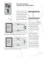
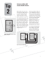
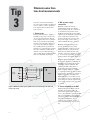
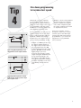
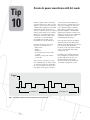
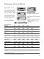
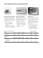
10 Practical Tips
You Need to Know About
Your Power Products
Simple ways to improve
your operation and
measurement capabilities
Use remote sensing to
compensate for load-lead effects
Tip
1
When your power supply leaves the
factory, its regulation sense terminals
are usually connected to the output
terminals. This limits the supply’s
voltage regulation abilities, even with
very short leads. The longer the leads
and the higher the wire gauge, the
worse the regulation gets (Figure 1).
Compare the output impedance of a
well-regulated 10 A supply, which
might have an output impedance of
0.2 mΩ, with the resistance of copper
wire:
I3
0.015 Ω lead resistance
+
+S
Power supply
programmed
for 5 V, 10 A
5V
Load
4.7 V
–S
–
0.015 Ω lead resistance
Load leads are
6 foot, AWG 14
0.015 Ω lead resistance
+
+S
5.3 V
–S
–
I2
0.015 Ω lead resistance
Load leads are
6 foot, AWG 14
Figure 2: Using remote sensing to correct the lead-load problem
2
Load
Resistance in mΩ/ft (at 20° C)
22
20
18
16
14
12
10
16.1
10.2
6.39
4.02
2.53
1.59
0.999
And regulation gets even worse if
you use a relay to connect power to
the load.
T3
Remote sensing, in which you connect
the sense terminals of the power
supply’s internal feedback amplifier
directly to the load, lets the power
supply regulate its output at the
load terminals, rather than at its
own output terminals (Figure 2).
The supply voltage shifts as necessary
to compensate for the resistance of
the load leads, relays, or connectors,
thereby keeping the voltage at the
load constant.
To implement remote sensing,
disconnect the local sense leads
from the output terminals. Use
twisted two-wire shielded cable to
connect the power supply sensing
terminals to the sense points on the
load. (Don’t use the shield as one of
the sensing conductors.) Connect
one end of the shield to ground and
leave the other end unconnected.
Figure 1: The effects of six feet of AWG 14-gauge leads without remote sensing
Power supply
programmed
for 5 V, 10 A
AWG wire size
5V
Sensing currents are typically less
than 10 mA, and as a general rule,
you should keep the voltage drop in
the sense leads to less than 20 times
the power supply temperature
coefficient (usually stated in mV/°C).
This is easy to achieve with readily
available shielded two-wire cable.
Increase safety with
remote disable feature
Tip
2
Remote disable offers a safe way to
shut down a power supply to respond
to some particular operating condition
or to protect system operators (in
response to a cabinet door being
opened unexpectedly or someone
pushing a panic button, for instance).
+5 V
To microprocessor
RI
Com
DFI
From microprocessor
Remote inhibit (RI) is an input to the
power supply that disables the output
when the RI terminal is pulled low
(Figure 1). Shorting the normally open
switch turns off the supply’s output.
You could also use a logic chip with
an open collector transistor output
instead of the switch. Figure 1 also
shows a discrete fault indicator (DFI)
that you can use to signal an operator
or other components in the system
when the power supply detects a
user-defined fault.
Com
Figure 1. Remote inhibit and discrete fault
indicator schematic
Almost any operating condition can
create a DFI signal. For example, to
generate a DFI signal when the load
draws excessive current, enable the
over-current protection (OCP) mode,
program the unit to generate a DFI
signal when it enters constant current
mode, then program the maximum
current the load normally draws.
If the load current exceeds the
maximum, the DFI output goes low,
disables the power supply, and
informs the operator of the overcurrent condition (or performs
another user-defined function),
without tying up the system bus or
interrupting the system controller.
You can daisy chain DFI and RI as
shown in Figure 2. If one supply
detects a fault, all supplies in the
system are disabled. Using this
approach, you can chain together
an unlimited number of supplies.
RI
RI
Com
Com
Power supply
#1
Power supply
#2
DFI
DFI
Com
Com
T2
Figure 2. Daisy-chained DFI and RI
T1
3
Eliminate noise from
low-level measurements
Tip
3
Noise in low-level measurements
can come from a number of different
sources, and it’s easier to eliminate
noise than to filter it. Check these
noise sources:
1. Power supply
Starting with a low-noise supply is
naturally a great way to keep noise
out of your measurements. Linear
power supplies have lower commonmode noise currents and generally
operate at low frequency. However,
you can use switch-mode supplies
successfully if their specifications
include a low common-mode current.
As a rule of thumb, common-mode
current over 20-30 mA is likely to
cause trouble. Keep reading for hints
on how to minimize the problem.
Shield
+
C
–
Power
supply
Load
+S
–S
Shield
Figure 1: Minimizing radiated pick-up with twisted shield leads for both output and
remote sense leads
4
2. DUT to power supply
connections
Minimize conducted noise by
eliminating ground loops. Ideally,
there should be only one connection
to ground. In rack systems, where
multiple ground points are inevitable,
separate the dc distribution path from
other conductive paths that carry
ground currents. If necessary, float
the power supply (don’t connect
either terminal directly to ground).
Minimize radiated pick-up (both
electric and magnetic) by using
twisted shielded conductors for the
output and remote sense leads. To
make sure the shield doesn’t carry
current, connect the shield to ground
at one end only, preferably the singlepoint ground on the supply (Figure 1).
Minimize the power supply’s commonmode noise current by equalizing the
impedance to ground from the plus
and minus output terminals. Also
equalize the DUT’s impedance to
ground from the plus and minus
input terminals. Magnetic coupling
or capacitive leakage provide a return
path for noisy ground loop current at
higher frequencies. To balance the
DUT’s impedance to ground for your
test frequencies, use a common-mode
choke in series with the output leads
and a shunt capacitor from each lead
to ground.
3. Current variations to the DUT
Rapid changes in the DUT’s current
demand cause voltage spikes. To
prevent this, add a bypass capacitor
close to the load. The capacitor should
have a low impedance at the highest
testing frequencies. Avoid imbalances
in load lead inductance; direct
connections to the DUT, such as
twisted shielded pair, are your best
bet.
Tip
4
Use down programming
to increase test speed
Under light or no load conditions,
a power supply’s output capacitor
discharges slowly. If you’re using the
supply as a static voltage source, this
is not problematic, but when you’re
making tests at varying voltage levels,
slow discharge means slow tests.
Down programming circuits in power
supplies rapidly decrease the output
voltage, reducing discharge times by
hundreds of milliseconds. Agilent
Technologies power supplies use two
types of down programming circuits:
Figure 1: A down programming circuit
with an FET across the output terminals
• In Figure 2, the down programmer
lies between the power supply’s
positive terminal and a negative
source. This configuration pulls
the output completely down with
no degradation near zero.
Some power supplies, such as
the Agilent 663xA series, can sink
currents equal to their full output
current rating. This sink current is
programmable, so you can use the
supply both as a programmable
source and load.
• In Figure 1, an FET is placed across
the output terminals. Whenever
the output voltage is higher than
the programmed value, the FET
activates and discharges the output
capacitor. The FET can sink currents
ranging from 10 percent to
20 percent of the supply’s output
current rating. The maximum load
at low voltages is limited to the
On resistance of the FET plus the
series monitoring resistor, resulting
in a slight degradation of the down
programming current near zero
volts.
Figure 2: A down programmer situated
between power supply’s positive output
and a negative source
5
Tip
5
Simplify setup with autoranging
power supplies
With bench and rack space at a
premium, having the ability to
produce a wide range of voltage
and currents with one power supply
is beneficial. Applications that
require many voltage and current
combinations require many power
supplies or a very large power
supply to span the largest voltage
and current combination. For
example, a dc/dc converter is tested
under several voltage and current
combinations at about the same
power level.
A very basic dc power supply has a
rectangular output (Figure 1). It has
a maximum voltage setting (Vmax)
and a maximum current setting (Imax)
with a single maximum power point
(Pmax) which equals Vmax * Imax.
This creates a rectangular output
characteristic.
More advanced power supplies
have multi-range outputs. For
example, a dual-range power supply
(Figure 2) has two rectangular output
characteristics, each having a
different Vmax and Imax. However,
both output characteristics have
the same Pmax but at two different
points. The power supply can switch
between the different ranges to
satisfy both rectangular output
characteristics.
Autoranging outputs (Figure 3) satisfy
many different voltage and current
combinations that are limited by
Pmax. The output characteristic
follows a constant Pmax curve
allowing for several different power
curves rated at the same power
level, Pmax.
Using autoranging outputs simplifies
the test setup by eliminating the
need for many power supplies.
Supplies such as the Agilent N675xA
and N676xA have autoranging
outputs that help do this and
drive the cost of test down.
Figure 1: Rectangular output characteristic
Figure 2: Dual-range output characteristic
6
Figure 3. Autoranging output characteristic
Connect power supplies in
series or parallel for higher output
Tip
6
+
Power supply
#1 –
EM
+
Power supply
#2 –
E1
+
Power supply
#3 –
E2
EL
RL
Connecting two or more power
supplies in series (Figure 1) provides
higher voltages, but observe these
precautions:
Connecting two or more power
supplies in parallel (Figure 2)
provides higher currents, but again,
observe these precautions:
• Never exceed the floating voltage
rating of any of the supplies.
• Never subject any of the power
supplies to negative voltages.
• One unit must operate in constant
voltage (CV) mode and the other(s)
in constant current (CC) mode.
• The output load must draw enough
current to keep the CC unit(s) in
CC mode.
Program each power supply
independently. If two supplies are
used, program each one for 50% of
the total output voltage. If three
supplies are used, program each
supply for about 33% of the total
output voltage. Set the current limit
of each supply to the maximum that
the load can safely handle.
The Agilent N6700 supplies have
a grouping function that virtually
parallels outputs. Output channels
can be configured or “grouped” to
create a single output with higher
current and power capability.
EL = EM + E1 + E2
Figure 1: Connecting units in series
+
Power supply
#2 –
+
Power supply
#1 –
IM
Program the current limit of each
unit to its maximum value and
program the output voltage of the CV
unit to a value slightly lower than the
CC unit(s). The CC units supply the
maximum output current that they
have been set to and drop their
output voltage until it matches the
voltage of the CV unit, which supplies
only enough current to fulfill the total
load demand.
+
Power supply
–
#3
I1
I2
IL
RL
IL = IM + I1 + I2
Figure 2: Connecting units in parallel
7
R
Tip
7
Simplify battery drain analysis
with analysis tools
To adequately specify the power
source for products that exhibit
pulsed and dynamic current loading
(such as digital cellular phone and
hard drives), you need to evaluate
both the peak and dc averages
current draws.
You could use an oscilloscope to
monitor a shunt or a current probe,
but this approach raises issues with
voltage drops, ground loops, common
mode noise, space, and calibration.
As a simpler and cheaper alternative,
use a power supply with built-in
measurement capabilities. The
Agilent 66300 mobile communications
dc sources store up to 4,096 data
points at sample intervals from 15 µs
to 31,200 s. Like an oscilloscope, they
acquire pre- and post-trigger buffer
data by crossing a user-set threshold.
The Agilent 14565B device characterization software is an automation
tool compatible with the 66319/21B
or D. These four sources have battery
emulation capabilities and work
with the software to accurately test
today’s communication devices as
well as your next generation designs
for cell phones, PDAs, Bluetooth™
enabled devices, and wireless LAN
access devices. The software features
dynamic current characterization
(Figure 1), data logging (Figure 2),
and CCDF measurements (Figure 3).
Figure 1. Waveform capture and analysis
using the Agilent 14565B software.
Figure 2. Data logging and analysis using the
Agilent 14565B software.
Figure 3. Complementary cumulative distribution function (CCDF)
capture and analysis using the Agilent 14565B software.
8
Tip
8
Characterize inrush current with
an ac power source/analyzer
The inrush current characteristics of
ac-dc switch mode power supplies
vary with the turn-on phase of the
voltage cycle. Usually, these power
supplies have input capacitors that
draw high peaks of inrush current as
they charge from the rectified ac line
at turn-on. Characterizing inrush
current versus turn-on phase can
provide some important design
insights:
Bus trigger
Output
voltage
Start up
phase of
40 degrees
Inrush current
Peak current measurement
Digitized inrush
current
data points
Figure 1: An inrush current measurement at 40° using Agilent 6800 series ac power
source/analyzers
• Uncover component stresses
• Check to see if a product produces
ac mains disturbances that
interact with other products
connected to the same branch
circuit
• Select proper fuses and circuit
breakers
However, this can be a challenging
measurement because you have to
synchronize the current digitization
and peak current measurement with
the startup phase of the voltage.
Worst case inrush currents occur
near the voltage cycle’s peak and
when the ac input capacitor of the
DUT is fully discharged at startup.
Therefore, you must perform tests at
incremental voltage startup phases
from about 40° to 90° (Figure 1) and
let the DUT’s ac input capacitor
discharge between tests.
A traditional test setup includes an
ac source with programmable phase
capability and an output trigger port,
a digital oscilloscope, and a current
probe. However, using an advanced
ac power source/analyzer such as the
Agilent 6800 series ac power
source/analyzers is easier because
they have built-in generation, current
waveform digitization, peak current
measurement, and synchronization
capabilities that let you perform
inrush current characterization
without cabling and synchronizing
separate instruments.
On the dc side, the Agilent N6705A
dc power analyzer helps characterize
the power of a device much like the
ac power source/analyzer, except
for dc power.
9
Tip
9
Use a power supply to
measure DUT supply current
Accurately measuring DUT supply
currents above 10 A is beyond the
range of the typical DMM in ammeter
mode. You could use an external
shunt and the DMM’s voltage mode,
but using the power supply itself is a
better solution. Many supplies include
an accurate measurement system,
including a shunt. Current (with the
internal shunt) or voltage measurements at the DUT can be as simple
as sending a MEAS command to the
power supply.
The following table shows the level of
measurement accuracy you can expect
with a good-quality supply:
Output level
Typical accuracy
Full
10% of full output
1% of full output
0.1% to 0.5%
0.5% to 1%
near 10%
While the advantages of using the
power source to measure high currents
is clear, using it to measure low
currents may not be as obvious.
A system DMM has 0.01 percent to
0.1 percent accuracy, although this
doesn’t include other possible errors
that can affect the measurement, such
as cabling. In contrast, the power
supply accuracy figures in the table
include all applicable factors.
10
A good system DMM can measure
current down to the picoamp level,
but you rarely need to measure DUT
supply currents this low. In most cases,
the toughest measurement will involve
current draw by a battery-powered
device in sleep mode (such as a
cellular phone), where measuring
1-10 mA with reasonable accuracy
is usually all you need.
Most power supplies’ current readback
performs well between full scale and
10% of full scale. You can also choose
a power supply with multiple range
readback. For example, power sources,
such as the Agilent N676xA precision
modules, offer full scale accuracy of
0.04% + 15 µA at low range (100 mA)
or 0.04% + 160 µA at high range (3 A).
Create dc power waveforms with list mode
Tip
10
Instead of using a DAC or arbitrary
waveform generator to drive a power
supply to create dc power waveforms,
consider using a single power product
with list mode. List mode lets you
generate complex sequences of output
changes with rapid, precise timing
which may be synchronized with
internal or external signals. They
contain up to 512 individually
programmed steps and can be
programmed to repeat themselves.
Using list mode helps you create
dc power waveforms such as:
• Pulse trains
• Ramps
• Staircases
• Low frequency sinewaves with
dc offset
• Arbitrary voltage and current
waveforms
You can create a sequence of up to
512 command steps to define voltage
or current steps and set dwell times
for each step. These waveforms can
also trigger on internal or external
events and be repeated (Figure 1).
Once the list of commands is stored
in the power supply, the entire list
is executed by a single command.
This reduces command processing
time and simplifies code. Example
applications include powering power
supply rejection ratio test, simulating
automotive crank profiles, and
generating pulse dropouts.
Power products such as the Agilent
N675xA and N676x modules in the
Agilent N6700 Modular Power System
have list mode. The maximum
frequency of the waveform is limited
by the power module and voltage
setting of the test.
In addition, the Agilent N6705A dc
Power Analyzer is a unique bench
product with list mode. You can
program arbitrary waveforms
directly from the front panel without writing a single line of code.
Trigger
0 1
2
3
4
5
List Count = 1
List Count = 2
Figure 1: An arbitrary voltage waveform example with a repeat count of 2.
11
Power
products
that do more and
less
demand
Agilent Technologies’ “one-box” philosophy means we pack more and more capability into the power products
themselves, in some cases giving you a rack’s worth of capability in a single box. By offering more, these products
demand less from you—fewer instruments, less rack space, simpler test setups, and lower cost of ownership.
Modular Power Systems (MPS)
With rack space at a premium, the Agilent 66000 and N6700 modular power
systems’ growing popularity is no surprise. Mix and match modules to fit the
needs of many applications. These systems are small, flexible, and fast.
66000 MPS
• High power density – up to
eight supplies in seven inches
of rack space
• Low noise, stable power
• High accuracy programming
and readback
N6700 MPS
• Up to four supplies in 1.25 inches
of rack space
• Flexible – three performances:
basic, hi-perf, and precision
modules
• Easy connectivity – LXI Class C
with GPIB, LAN, and USB
The Agilent N6705A is the bench
version of the N6700. It uses the
same modules as the N6700 and
combines the functionality of
many instruments for dc power
characterization.
• Feature rich – up to 4 supplies,
oscilloscope-like display, arb
capabilities
• Output synchronization controls,
inrush current testing, data
logging
• External BNC and digital port for
easy triggering
Modular power systems
Model
Output ratings at 40° C
Output voltage
Output current
Maximum power
66101A
66102A
66103A
66104A
66105A
66106A
0 to 8 V
0 to 16 A
128 W
0 to 20 V
0 to 7.5 A
150 W
0 to 35 V
0 to 4.5 A
157.5 W
0 to 60 V
0 to 2.5 A
150 W
0 to 120 V
0 to 1.25 A
150 W
0 to 200 V
0 to 0.75 A
150 W
Basic Models
Output ratings at 40° C
Output voltage
Output current
Maximum power
N6731A/41A
N6732A/42A
N6733A/43A/73A N6734A/44A/74A
N6735A/45A/75A N6736A/46A/76A
5V
10 A/20 A
50 W/100 W
8V
6.25 A/12.5 A
50 W/100 W
20 V
2.5 A/5 A/15 A
50 W/100 W/300 W
35 V
1.5 A/3 A/8.5 A
52.5 W/105 W/300 W
60 V
0.8 A/1.6 A/5 A
50 W/100 W/300 W
Hi-Perf, Precision Models
Output ratings at 40° C
Output voltage
Output current
Maximum power
N6751A/52A
N6753A**
N6754A
N6761A/62A *
50 V
5 A/10 A
50 W/100 W
20 V
50 A
300 W
60 V
20 A
300 W
50 V
1.5 A/3 A
50 W/100 W
* Precision power supplies
** Module not compatible with the N6705A.
12
100 V
0.5 A/1 A/ 3 A
50 W/100 W/300 W
Power you can count on year after year
We’ve been a leader in the power
products business for more than
half a century because engineers like
you know they can count on Agilent
performance, reliability and value.
Even our least-expensive dc supplies
offer low ripple and noise with tight
load and line regulation. Our high
precision products give you the exact
power levels you need, with accurate
readback measurements to match.
Plus, every product you see here is
covered by a one-year warranty.
Single-output dc supplies
These supplies will clean up your ATE
power without cleaning out your budget. Not
only do you buy more performance with the
Agilent 6600 or N5700 series, their one-box
integration means you’ll buy less equipment
overall, too.
• Clean, reliable dc power from 40 W to 6.6 W
• Designed for fast, easy system integration
• Built-in V & I readback for one-box
convenience
• LXI Class C N5700 supplies with GPIB,
LAN, and USB
To learn more about these power
solutions, visit our Web site at
www.agilent.com/find/power.
Single-output dc supplies
40 W and 100 W
Voltage
Current
200 W
Output voltage
Output current (40° C)
500 W
Output voltage
Output current (40° C)
750 W
1.5 kW
Output voltage
Maximum current (40°C)
750 W (continued)
1.5 kW (continued)
Output voltage
Maximum current (40°C)
2 kW
Output voltage
Output current
5 kW
Voltage
Current
6612C
6632B
6633B
6634B
0 to 20 V
0 to 2 A
0 to 20 V
0 to 5 A
0 to 50 V
0 to 2 A
0 to 100 V
0 to 1 A
6541A*
6641A
6542A*
6642A
6543A*
6643A
6544A*
6644A
6545A*
6645A
0 to 8 V
0 to 20 A
0 to 20 V
0 to 10 A
0 to 35 V
0 to 6 A
0 to 60 V
0 to 3.5 A
0 to 120 V
0 to 1.5 A
6551A*
6651A
6552A*
6652A
6553A*
6653A
6554A*
6654A
6555A*
6655A
0 to 8 V
0 to 50 A
0 to 20 V
0 to 25 A
0 to 35 V
0 to 15 A
0 to 60 V
0 to 9 A
0 to 120 V
0 to 4 A
N5741A **
N5761A **
N5742A **
N5762A **
N5743A
N5763A
N5744A **
N5764A **
N5745A
N5765A
N5746A **
N5766A **
0 to 6 V
100 A / 180 A
0 to 8 V
90 A / 165 A
0 to 12.5 V
60 A / 120 A
0 to 20 V
38 A / 76 A
0 to 30 V
25 A / 50 A
0 to 40 V
19 A / 38 A
N5747A
N5767A
N5748A **
N5768A **
N5749A
N5769A
N5750A
N5770A
N5751A
N5771A
N5752A **
N5772A **
0 to 60 V
12.5 A / 25 A
0 to 80 V
9.5 A / 19 A
0 to 100 V
7.5 A / 15 A
0 to 150 V
5 A / 10 A
0 to 300 V
2.5 A / 5 A
0 to 600 V
1.3 A / 2.6 A
6571A*
6671A
6572A*
6672A
6573A*
6673A
6574A*
6674A
6575A*
6675A
0 to 8 V
0 to 220 A
0 to 20 V
0 to 100 A
0 to 35 V
0 to 60 A
0 to 60 V
0 to 35 A
0 to 120 V
0 to 18 A
6680A
6681A
6682A
6683A
6684A
0 to 5 V
0 to 875 A
0 to 8 V
0 to 580 A
0 to 21 V
0 to 240 A
0 to 32 V
0 to 160 A
0 to 40 V
0 to 128 A
6690A
6691A
6692A
0 to 15 V
0 to 440 A
0 to 30 V
0 to 220 A
0 to 60 V
0 to 110 A
(40° C, then derated linearly 1%/° C to 55° C)
6.6 kW
Voltage
Current
(40° C, then derated linearly 1%/° C to 55° C)
* Economy versions with identical specifications, but without GPIB.
** Supply is rated at the voltage and current combination – may be higher or lower than indicated.
13
Power products that do more and demand less
Dynamic measurement dc supplies
Solar array simulator (SAS)
Electronic Loads
The Agilent 66300 series are the first
power supplies with instantaneous
peak measurement capability, so you
no longer need a scope or high-speed
digital voltmeter to test devices that
draw pulsed current.
The Agilent E4350-series SAS
simulates the output characteristics
of a satellite’s solar panels. It’s also a
great example of our ability to create
unique power solutions to meet
unique application challenges.
• Ideal for testing wireless and
battery powered products
• Superior output transient
performance*
• Programmable output resistance*
• 14565B device characterization
software for battery drain analysis*
• Simulate I-V curves of a solar
array under various conditions
• Operate the system in three
different modes for maximum
flexibility
• Have fast recovery time
Agilent’s integrated electronic loads
help you save time, money, and rack
space while delivering precise control
and all the capabilities you need for
analyzing dc power sources and
devices. Use the programmable pulse
waveform generator or use analog
programming to simulate real-life
load conditions.
• Ideal for evaluating dc power
sources and power components
• Lower costs while improving
ease of use and test quality
• Single-input and modular units
with proven record of reliability
Dynamic measurement dc supplies
Model
Voltage
Current
Maximum power
Solar array simulator
66332A
66319B/D
66321B/D
E4350B
E4351B
0 to 20 V
0 to 5 A
100 W
0 to 15 V
0 to 3 A
45 W
0 to 15 V
0 to 3 A
45 W
0 to 65 V
0 to 8 A
480 W
0 to 130 V
0 to 4 A
480 W
Electronic Loads
Model
Input voltage
Input current
Max. current derated
linearly below 2 V
Maximum power
14
6060B, N3304A
6063B, N3303A
N3302A
N3306A
N3305A
N3307A
0 to 60 V
0 to 60 A
0 to 240 V
0 to 10 A
0 to 60 V
0 to 30 A
0 to 60 V
0 to 120 A
0 to 150 V
0 to 60 A
0 to 150 V
0 to 30 A
300 W
250 W
150 W
600 W
500 W
250 W
ac power source/analyzers
From avionics to uninterruptible
power supplies, customers are
demanding products that can use
power efficiently while handling all
kinds of ac line disturbances. To
make sure your products meet these
growing expectations, test them with
the Agilent 6800-series ac power
source/analyzers.
• The fast, easy way to generate
both clean and distorted ac power
for product testing
• A complete solution in a single,
compact, tightly integrated box
with graphical user interface
• Built-in 16-bit power analyzer
precisely measures all important
parameters
• dc output voltage capability of
±425 V (derated power)
ac Power Source/analyzers
Model
6811B
6812B
6813B
Max power
# of phases
375 VA
1
750 VA
1
1750 VA
1
Rms output voltage
Rms output current
0 to 300 V
0 to 3.25 A
0 to 300 V
0 to 6.5 A
0 to 300 V
0 to13 A
For more information, visit our Web site at www.agilent.com/find/power.
15
Agilent Email Updates
www.agilent.com/find/emailupdates
Get the latest information on the
products and applications you select.
Agilent Direct
www.agilent.com/find/agilentdirect
Quickly choose and use your test
equipment solutions with confidence.
Agilent
Open
www.agilent.com/find/open
Agilent Open simplifies the process
of connecting and programming
test systems to help engineers
design, validate and manufacture
electronic products. Agilent offers
open connectivity for a broad range
of system-ready instruments, open
industry software, PC-standard I/O
and global support, which are
combined to more easily integrate
test system development.
www.lxistandard.org
LXI is the LAN-based successor to
GPIB, providing faster, more efficient
connectivity. Agilent is a founding
member of the LXI consortium.
You’re trying to get the most from
your power products and get the
best power products for your
money—and this booklet is a great
place to start. You’ll find 10 easy
and practical ways to improve
power generation and measurement, along with a brief look
at our most popular power
instruments and systems.
For more information,
visit our Web site at
www.agilent.com/find/power.
Remove all doubt
Our repair and calibration services
will get your equipment back to you,
performing like new, when promised. You will get full value out of
your Agilent equipment throughout its lifetime. Your equipment
will be serviced by Agilent-trained
technicians using the latest factory
calibration procedures, automated
repair diagnostics and genuine parts.
You will always have the utmost
confidence in your measurements.
Agilent offers a wide range of
additional expert test and measurement services for your equipment,
including initial start-up assistance
onsite education and training, as well
as design, system integration, and
project management.
For more information on repair and
calibration services, go to:
www.agilent.com/find/removealldoubt
www.agilent.com
For more information on Agilent Technologies’
products, applications or services, please
contact your local Agilent office. The complete
list is available at:
www.agilent.com/find/contactus
Americas
Canada
Latin America
United States
(877) 894-4414
305 269 7500
(800) 829-4444
Asia Pacific
Australia
China
Hong Kong
India
Japan
Korea
Malaysia
Singapore
Taiwan
Thailand
1 800 629 485
800 810 0189
800 938 693
1 800 112 929
81 426 56 7832
080 769 0800
1 800 888 848
1 800 375 8100
0800 047 866
1 800 226 008
Europe
Austria
Belgium
Denmark
Finland
France
Germany
0820 87 44 11
32 (0) 2 404 93 40
45 70 13 15 15
358 (0) 10 855 2100
0825 010 700
01805 24 6333*
*0.14 /minute
Ireland
1890 924 204
Italy
39 02 92 60 8484
Netherlands
31 (0) 20 547 2111
Spain
34 (91) 631 3300
Sweden
0200-88 22 55
Switzerland (French) 41 (21) 8113811(Opt 2)
Switzerland (German) 0800 80 53 53 (Opt 1)
United Kingdom
44 (0) 118 9276201
Other European Countries:
www.agilent.com/find/contactus
Revised: May 7, 2007
Product specifications and descriptions
in this document subject to change
without notice.
© Agilent Technologies, Inc. 2007
Printed in USA, September 21, 2007
5965-8239E
Agilent Technologies