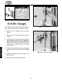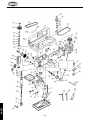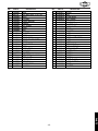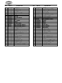
1
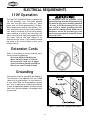
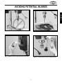
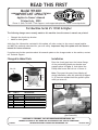
READ THIS FIRST
Model W1680
***IMPORTANT UPDATE***
Applies to Owner's Manual
Printed July, 2000
Phone #: (360) 734-3482 • Tech Support: [email protected] • Web: www.shopfox.biz
For Machine Serial #'s 13943 & Higher
The following changes were recently made to this machine since the owner's manual was printed:
Changed the depth stop bracket.
Added a chuck guard.
•
•
Aside from the information contained in this update, all other content in the owner's manual applies
and MUST be read and understood for your own safety. Important: Keep this update with the owner's
manual for future reference.
If you have any further questions about this manual update or the changes made to the machine, contact
our Technical Support.
Changed & Added Parts
Installation
Place the chuck guard over the bottom flange
of the pre-installed depth stop bracket (see
example photo in Figure 1), and tighten the
Phillips head screw and hex nut to secure it.
111
23A-1V2
111-1
111-2
111-1
111-2
111-3
111-4
111-5
REF
PART #
DESCRIPTION
23A-1V2
111
111-1
111-2
111-3
111-4
111-5
X1680023A-1V2
X1680111
XPS51M
XPN04M
XPHTEK47M
XPB107M
XPWN05M
DEPTH STOP BRACKET V2.12.12
CHUCK GUARD ASSEMBLY
PHLP HD SCR M4-.7 X 30
HEX NUT M4-.7
TAP SCREW M2.2 X 4.5
HEX BOLT M5-.8 X 12
WING NUT M5-.8
Note: To prevent the guard from slipping off
during installation, move the table up to support
it. Or, have an assistant hold the guard in place
while you secure it.
Depth Stop
Bracket
Figure 1. Example photo of installing chuck
guard assembly.
COPYRIGHT © FEBRUARY, 2013 BY WOODSTOCK INTERNATIONAL, INC.
#15656TS
WARNING: NO PORTION OF THIS MANUAL MAY BE REPRODUCED IN ANY SHAPE OR FORM WITHOUT
THE WRITTEN APPROVAL OF WOODSTOCK INTERNATIONAL, INC.
Printed in China
MODEL W1680
17" DRILL PRESS
INSTRUCTION MANUAL
Phone: 1-800-840-8420 • On-Line Technical Support: [email protected]
COPYRIGHT © 2000 BY WOODSTOCK INTERNATIONAL, INC.
WARNING: NO PORTION OF THIS MANUAL MAY BE REPRODUCED IN ANY SHAPE OR FORM WITHOUT
THE WRITTEN APPROVAL OF WOODSTOCK INTERNATIONAL, INC.
Printed in China
1.
7.
-1 -
PARTS
USE THE QUICK GUIDE PAGE LABELS TO SEARCH OUT INFORMATION FAST!
MAINTENANCE
6.
OPERATIONS
5.
ADJUSTMENTS
4.
ASSEMBLY
3.
SAFETY
2.
PAGE
INTRODUCTION ................................................................................2
ABOUT YOUR NEW DRILL PRESS ......................................................2
WOODSTOCK SERVICE AND SUPPORT ................................................2
WARRANTY AND RETURNS ..............................................................3
MACHINE SPECIFICATIONS ..............................................................3
SAFETY FIRST! ................................................................................4
STANDARD SAFETY INSTRUCTIONS ................................................4-5
DRILL PRESS SAFETY ....................................................................5
ELECTRICAL REQUIREMENTS ..........................................................6
AVOIDING POTENTIAL INJURIES ......................................................7
ASSEMBLY INSTRUCTIONS ..................................................................8
BOX CONTENTS ..........................................................................8
BASE AND COLUMN ......................................................................9
TABLE SUPPORT ....................................................................10-11
HEADSTOCK ..........................................................................12-13
HANDLES..................................................................................13
DRILL CHUCK AND ARBOR ........................................................14-15
ARBOR REMOVAL........................................................................15
ADJUSTMENTS ..............................................................................16
SPEED CHANGE ......................................................................16-17
SPINDLE ADJUSTMENTS ..............................................................17
TABLE ADJUSTMENTS ..................................................................18
OPERATIONS..................................................................................19
TEST RUN ................................................................................19
DRILL CHANGES ........................................................................20
MAINTENANCE................................................................................21
GENERAL..................................................................................21
TABLE AND BASE ........................................................................21
LUBRICATION ............................................................................21
CLOSURE ......................................................................................22
WIRE DIAGRAM ..............................................................................23
PARTS BREAKDOWN AND PARTS LISTS ........................................24-25
INTRODUCTION
Table Of Contents
INTRODUCTION
INTRODUCTION
ABOUT YOUR NEW DRILL PRESS
This new Shop Fox® Drill Press has been specially designed by Woodstock International, Inc. to provide
many years of trouble free service. Close attention to detail, ruggedly built parts and a rigid quality control program assure safe and reliable operation.
The Model W1680 Drill Press is capable of a wide variety of drilling operations in metal, wood and plastic. The tilting table allows drilling angles from 90˚ to 0˚. Precision ground spindle, table, base and column ensure dependable accuracy. The W1680 is packaged with a drill chuck, motor, work light and paddle switch with removable safety key.
Woodstock International, Inc. is committed to customer satisfaction in providing this manual. It is our
intent to make sure all the information necessary for safety, ease of assembly, practical use and durability of this product be included.
If you should have any comments regarding this manual, please feel free to contact us at:
Woodstock International, Inc.
P.O. Box 2309
Bellingham, WA 98227
WOODSTOCK SERVICE AND SUPPORT
We stand behind our machines! In the event that a defect is found, parts are missing or questions arise
about your machine, please contact Woodstock International Service and Support at 1-360-734-3482 or
at [email protected]. Our knowledgeable staff will help you troubleshoot problems, send
out parts or arrange warranty returns.
-2 -
Woodstock International, Inc. warrants all SHOP FOX® machinery to be free of defects from workmanship and materials for a period of 2 years from the date of original purchase by the original owner. This
warranty does not apply to defects due directly or indirectly to misuse, abuse, negligence or accidents,
lack of maintenance, or to repair or alterations made or specifically authorized by anyone other than
Woodstock International, Inc.
Woodstock International, Inc. will repair or replace, at its expense and at its option, the SHOP FOX®
machine or machine part which in normal use has proven to be defective, provided that the original
owner returns the product prepaid to the SHOP FOX® factory service center or authorized repair facility
designated by our Bellingham, WA office, with proof of their purchase of the product within 2 years, and
provides Woodstock International, Inc. reasonable opportunity to verify the alleged defect through
inspection. If it is determined there is no defect, or that the defect resulted from causes not within the
scope of Woodstock International Inc.'s warranty, then the original owner must bear the cost of storing
and returning the product.
This is Woodstock International, Inc.'s sole written warranty and any and all warranties that may be
implied by law, including any merchantability or fitness, for any particular purpose, are hereby limited
to the duration of this written warranty. We do not warrant that SHOP FOX® machinery complies with
the provisions of any law or acts. In no event shall Woodstock International, Inc.'s liability under this warranty exceed the purchase price paid for the product, and any legal actions brought against Woodstock
International, Inc. shall be tried in the State of Washington, County of Whatcom. We shall in no event
be liable for death, injuries to persons or property or for incidental, contingent, special or consequential damages arising from the use of our products.
Every effort has been made to ensure that all SHOP FOX® machinery meets high quality and durability
standards. We reserve the right to change specifications at any time because of our commitment to continuously improve the quality of our products.
Machine Specifications
Capacities:
Spindle Travel ..........................................................................................................31⁄4''
Max. Distance, Spindle to Base ........................................................................................49''
Max. Distance, Spindle to Table ....................................................................................311⁄2''
Spindle Taper ..........................................................................................................MT #3
Swing ......................................................................................................................17''
Chuck Size ............................................................................................5⁄8'' (16mm), keyed
Speeds ......................................................................................................................12
Range of Speeds............................150, 260, 320, 380, 480, 540, 980, 1160, 1510, 1650, 2180, 3050 RPM
Drilling Capacity ........................................................................................3⁄4'' Diameter in Steel
Motor:
Type ......................................................................................TEFC Capacitor Start Induction
Horsepower..............................................................................................................1 HP
Phase ⁄ Cycle........................................................................................Single Phase ⁄ 60 Hz
Amps ........................................................................................................................10
Voltage ............................................................................................................110V Only
RPM ......................................................................................................................1720
Power Transfer ................................................................................................V-Belt Drive
Bearings............................................................................Shielded & Lubricated Ball Bearings
Switch ....................................................................Toggle ON/OFF Switch, w/ Safety Lock Tab
-3 -
INTRODUCTION
WARRANTY AND RETURNS
SAFETY
SAFETY FIRST!
READ MANUAL BEFORE OPERATING MACHINE
FAILURE TO FOLLOW INSTRUCTIONS BELOW WILL
RESULT IN PERSONAL INJURY
Indicates an imminently hazardous situation which, if not avoided, WILL
result in death or serious injury.
Indicates a potentially hazardous situation which, if not avoided, COULD
result in death or serious injury.
Indicates a potentially hazardous situation which, if not avoided, MAY
result in minor or moderate injury. It may also be used to alert against
unsafe practices.
NOTICE
This symbol is used to alert the user to useful information about proper
operation of the equipment.
1. Thoroughly read the instruction manual before operating your machine. Learn the applications,
limitations and potential hazards of this machine. Keep manual in a safe, convenient place for future
reference.
2. Keep work area clean and well lighted. Clutter and inadequate lighting invite potential hazards.
3. Ground all tools. If a machine is equipped with a three-prong plug, it must be plugged into a threehole electrical outlet or grounded extension cord. If using an adapter to aid in accommodating a twohole receptacle, ground using a screw to a known ground.
4. Wear eye protection at all times. Use safety glasses with side shields or safety goggles, meeting the
national safety standards, while operating this machine.
5. Avoid dangerous environments. Do not operate this machine in wet or open flame environments.
Airborne dust particles could cause an explosion and severe fire hazard.
6. Ensure all guards are securely in place and in working condition.
7. Make sure switch is in the “OFF” position before connecting power to machine.
8. Keep work area clean; free of clutter, grease, etc.
9. Keep children and visitors away. All visitors should be kept a safe distance away while operating
unit.
10. Childproof workshop with padlocks, master switches or by removing starter keys.
-4 -
11. Disconnect machine when cleaning, adjusting or servicing.
12. Do not force tool. The machine will do a safer and better job at the rate for which it was designed.
13. Use correct tool. Do not force machine or attachment to do a job for which it was not designed.
14. Wear proper apparel. Do not wear loose clothing, neck ties, gloves, jewelry, etc.
16. Use proper extension cord. When using an extension cord, make sure it is in good condition. When
extension cord is 100' and less in length, use those that are rated Hard Service (grade S) or better,
and that have a conductor size of 16 A.W.G. A drop in line voltage, loss of power and overheating
can result when using an undersized cord. The extension cord should have a ground wire and ground
plug pin, as well.
17. Keep proper footing and balance at all times.
18. Do not leave machine unattended. Wait until it comes to a complete stop before leaving the area.
19. Perform machine maintenance and care. Follow lubrication and accessory attachment instructions
in the manual.
20. Keep machine away from open flame. Operating machines near pilot lights and/or open flames creates a high risk if dust is dispersed in the area. Dust particles and an ignition source may cause an
explosion. Do not operate the machine in high risk areas, including but not limited to, those mentioned above.
Additional Safety Instructions For Drill Presses
1.
Always operate your drill press at speeds that are appropriate for the drill bit size and the material that you are drilling.
2.
Feed the drill bit evenly into the workpiece. Back the bit out of deep holes and clear the chips
with a brush after you have turned the machine off.
3.
Make sure the drill bit you are using is tightened properly. Use only round, hex or triangular shank
drill bits.
4.
Never do maintenance or change speeds with this machine plugged in.
5.
Never use tools that are in poor condition. Cutting tools that are dull or damaged are difficult to
control and may cause serious injury.
6.
Never drill sheet metal unless it is clamped securely to the table.
7.
Work should be positioned in such a way as to avoid drilling into the table.
8.
A face shield used with safety glasses is recommended.
9.
Always clamp workpiece securely to table before drilling. Never hold a workpiece by hand while
drilling.
10. Habits – good and bad – are hard to break. Develop good habits in your shop and safety will become
second-nature to you.
-5-
SAFETY
15. Remove adjusting keys and wrenches. Before turning the machine on, make it a habit to check that
all adjusting keys and wrenches have been removed.
SAFETY
ELECTRICAL REQUIREMENTS
110V Operation
The Shop Fox® W1680 Drill Press is supplied for
110 volt operation, only. The motor supplied
with your new drill press is rated at 1 horse
power and will draw approximately 10 amps.
When choosing an outlet for this machine, consider using one with a 15 amp circuit breaker or
fuse. Keep in mind that a circuit being used by
other machines or tools at the same time will
add to the electrical load being applied by the
drill press. Add up the load ratings of all
machines on the circuit. If this number exceeds
the rating of the circuit breaker or fuse, use a
different outlet.
This equipment must be grounded. Verify
that any existing electrical outlet and circuit
you intend to plug into is actually grounded.
If it is not, it will be necessary to run a separate 12 A.W.G. copper grounding wire from
the outlet to a known ground. Under no circumstances should the grounding pin from
any three-pronged plug be removed. Serious
injury may occur.
Extension Cords
When it is necessary to use an extension cord,
use the following guidelines:
•Use cords rated for Hard Service
•Never exceed a length of 100 feet
•Use cords with 14 ga. wire or bigger
•Insure cord has a ground wire and pin
•Do not use cords in need of repair
Grounding
Never remove grounding pin.
This machine must be grounded! See Figure 1.
The electrical cord supplied with the W1680
comes with a grounding pin. Do not remove it.
If your outlet does not accommodate a ground
pin, have it replaced by a qualified electrician
or have an appropriate adapter installed. Please
note: when using an adapter, the adapter must
be grounded.
Figure 1. Typical 110V 3-prong plug and outlet.
-6-
AVOIDING POTENTIAL INJURIES
SAFETY
Figure 2. Never drill, holding workpiece by hand.
Figure 3. Keep fingers away from spinning tool.
Fig. 4. Remove Switch Safety Key when not in use.
Figure 5. Unplug machine when changing bulbs.
-7 -
ASSEMBLY
ASSEMBLY INSTRUCTIONS
Figure 6. Components laid out for identification.
The following is a description of the components shipped with the Shop Fox® W1680 Drill Press. It is recommended that the components be laid out in a similar fashion to those in Figure 6. This will help in
identification before beginning assembly. Should any part be missing, examine the packaging carefully
and check under the belt guard. If any key parts are missing, call Woodstock International, Inc. at 360734-3482 or [email protected].
1.
2.
3.
4.
5.
6.
7.
8.
9.
10.Wedge
11.Hex Head Bolts (4)
12.Belt Cover Knob and Screw
13.Handle
14.Pinion Gear
15.Lock Handles (2)
16.Rack
17.Column Ring
Headstock Assembly
Base
Column
Table
Column Lock
Drill Chuck and Key
Drill Chuck Arbor
Spindle Handles (3)
Allen® Wrenches (2)
-8-
While the main components of the Shop Fox® W1680 Drill Press are assembled at the factory, some
assembly is required. The following is the recommended sequence best suited for final assembly.
TOOLS REQUIRED: You will need a 11⁄16" open end wrench, a rubber or wooden mallet and a 5mm Allen®
wrench (supplied).
Base/Column
Wear safety glasses during the entire assembly
process. Failure to comply may result in serious
personal injury.
The W1680 Drill Press is a floor model and
should be secured to the floor or the base should
be extended with plywood to maximize stability. The use of a mobile base is not recommended.
1. Ensure machine is unplugged!
2. Secure base to floor with the appropriate
anchor bolts (not included). See Figure 7.
Figure 7. Secure base to floor.
OR
2. Secure base to a 4' x 4' x 3⁄4" sheet of plywood. Base should be positioned along the
back edge of plywood and centered from
side to side as in Figure 8. Use base to lay
out hole pattern. Drill holes and secure base
to plywood with carriage bolts.
3. Place the column on the base and line up
the 4 mounting holes. Secure tightly with
the three M10-1.5 x 40mm hex head bolts
included using the open end wrench provided.
Figure 8. Secure base to plywood.
-9-
ASSEMBLY
Do not connect the
machine to power at this
time. The machine must
remain
unplugged
throughout the entire
assembly process. Failure
to do this may result in
serious personal injury.
Table Support
1. Thread the 12mm table lock handle 3 turns
into the table support bracket.
ASSEMBLY
2. Insert the pinion into the hole on the side of
the table support bracket from the inside,
starting with the pinion shaft. Figure 9.
Align setscrew in crank handle with flat,
Figure 10, on pinion shaft and secure using
the 3mm Allen® wrench provided.
3. Examine the rack and note that the gear
teeth extend further on one end than the
other.The shorter end must be positioned
down. Insert the rack into the table support
bracket and align with pocket. The end of
the rack where the gear teeth are closest to
the end should be positioned down as in
Figure 11. The gear teeth on the rack must
also face out.
Figure 9. Insert the pinion gear from the inside.
Figure 10. Align setscrew with flat on pinion.
Figure 11. Correct rack orientation.
-10-
Table Support, Cont.
4. Slide the table support bracket onto the column while holding the rack in place. Allow
the bracket to go down until the bottom of
the rack contacts the shoulder on the column support. Figure 12. Secure the table
with the lock handle.
5.
NOTICE
Use caution when tightening set screw. Over tightening will split column ring.
Figure 13. Inside bevel in the correct position.
-11-
ASSEMBLY
Figure 12. Bottom of rack in position.
Slide the column ring onto the column with the
inside bevel in the down position. Figure 13.
Adjust the ring until the tip of the rack fits
inside the bevel. Tighten the setscrew on the
ring.
Head Stock
ASSEMBLY
The headstock represents a heavy load. Seek
assistance before beginning this step.
1. The bottom of the headstock has a pocket
for inserting the column. An assistant will
be needed to position the pocket over the
column, as in Figure 14. Allow the headstock to slide down until it stops (approximately 4").
Figure 14. Align pocket in headstock with column.
2. Align the headstock directly over the foot of
the base by using a plumb bob. Lay a measuring tape or ruler across the drill press
base and find its center. Suspend the plumb
line from the center of the headstock label
and lower the bob until it is near the
tape/ruler as in Figure 15. Adjust headstock from side to side until the tip is
equidistant from the left and right sides.
Figure 15. Align headstock with base.
-12-
3. Tighten the two setscrews in Figure 16 to
secure the headstock to the column
Handles
Three handles are supplied with your new Drill
Press. Thread them into the hub. Figure 17.
Unplug the drill press
before replacing the light
bulb. Failure to do this
may result in serious personal injury.
Figure 17. Installing handles.
Installing Light Bulb
The Shop Fox® 17" Drill Press is fitted with a light
socket that accommodates standard sized bulbs.
Use only bulbs that are “safety coated” and
shatter resistant. The bulb will be exposed
at the bottom of the head casting which
helps with illumination. Impacts with a bulb
not “safety coated” may shatter, exposing
the electrical filaments and creating an
electrical shock hazard.
Figure 17b. Installing a light bulb.
Before installing a light bulb, unplug the drill
press. Secure bulb in opening behind the spindle
as in Figure 17b.
-13-
ASSEMBLY
Figure 16. Tighten setscrews to secure headstock.
Drill Chuck and Arbor
ASSEMBLY
The drill chuck is attached to the drill spindle by
means of a drill chuck arbor. Matched tapers on
the arbor and the back of the chuck create an
almost permanent assembly when properly
joined. To assemble the drill chuck and mount it
to the spindle, carefully follow the instructions
below:
Many of the solvents commonly used to
clean machinery can be highly flammable,
and toxic when inhaled or ingested. Always
work in well-ventilated areas far from
potential ignition sources when dealing
with solvents. Use care when disposing of
waste rags and towels to be sure they do
not create fire or environmental hazards.
Keep children and animals safely away
when cleaning and assembling this machine.
Chuck
Arbor
Key
Wedge
Figure 18. Chuck components identification.
1. The drill chuck, arbor and spindle socket
must be thoroughly cleaned before assembly. It is recommended that mineral spirits
be used for this task. Refer to the safety
warnings on the container of the mineral
spirits. Failure to clean the mating surfaces
may result in separation and wear.
2. Use the chuck key provided to adjust the
jaws of the chuck until they are well inside
the drill chuck body.
Figure 19. Seating the arbor into chuck.
3. Place the drill chuck on a workbench face
down. The arbor has a short taper and a
long taper. Place the short taper into the
socket in the back of the drill chuck and tap
with a rubber or wooden mallet. See Figure
19. If the chuck fails to remain secure on
the arbor, repeat step 1 and 2. Do not use
excessive force. The drill chuck and arbor
may be damaged.
Do not use gasoline or other petroleumbased solvents to remove this protective
coating. These products generally have low
flash points which makes them extremely
flammable. A risk of explosion and burning
exists if these products are used. Serious
personal injury may occur.
DO NOT use a steel hammer on the drill chuck
to seat it onto the spindle. Damage will occur
to the chuck and/or spindle which may make
them unusable or unsafe.
-14-
4. Slide the arbor into the spindle socket while
slowly rotating drill chuck. The socket has a
rectangular pocket in which the tang (or flat
portion of the arbor) fits into. Once the tang
is oriented correctly the drill chuck will not
rotate without turning the spindle.
5. Tap the end of the drill chuck with a rubber
or wooden mallet to seat the drill chuck.
See Figure 20.
Arbor Removal
Wear safety glasses when
removing drill chuck
from spindle. Failure to
comply may result in
serious personal injury.
A wedge is included with the Shop Fox® Drill
Press which aids in drill chuck arbor removal.
1. Rotate the spindle handles until a slot is
exposed in the side of the quill.
Figure 21. Inner and outer slots aligned.
2. Rotate the spindle until the inner slot is
aligned with the outer. See Figure 21. You
will see through the spindle when slot is
properly aligned.
3. Insert the wedge into the slot and allow
quill to rise, trapping the wedge. Hold the
drill chuck with one hand and tap on the
wedge with a hammer. See Figure 22.
Figure 22. Using wedge to remove arbor.
-15-
ASSEMBLY
Figure 20. Seating arbor into spindle.
ADJUSTMENTS
Speed Change
Unplug the drill press
before changing speeds
to avoid accidental start
up. Failure to do this may
result in serious personal
injury.
ADJUSTMENTS
Unplug the drill press before changing speeds.
The Drill Press has 12 speeds ranging from 140
to 3050 RPM. There is a speed chart located
under the belt guard and one on the following
page. Refer to these while reading these
instructions.
Figure 23. Loosening the lock knob.
1. Loosen the belt tension lock knobs on both
sides of the headstock.
See Figure 23.
2. The motor is now free to move. Rotate the
belt tension lever to take tension off the Vbelts.
3. Locate the desired speed on the chart and
move the V-belts to the desired V-grooves
on the motor, idler and spindle pulleys. See
Figure 24.
Figure 24. Adjusting belt to desired speed.
4. Rotate the belt tension lever until belts are
tight. See Figure 25. Tighten both lock
knobs.
5. Close the cover.
Never operate drill press
with belt cover in the
open position. Your hand
may become trapped in a
belt and serious personal
injury will occur.
Figure 25. Grasp the lever and turn.
-16-
More About Speed Changes
The speed chart above is included to help illustrate belt changes necessary to produce a desired speed.
Select the proper speed for the job at hand and find it on the speed chart above. Move the belts to the
indicated location on the chart. The belt setting in the example above, shows the spindle belt is in the
#1 position and the motor belt is in the #7 location. This will produce a speed of 1,650 RPM.
Spindle Adjustments
1. Loosen the depth collar lock knob. Figure
26.
2. Rotate the depth collar to the desired depth
indicated by the scale on the collar. Secure
the collar with the lock knob.
3. Test the depth stop by measuring how far
the spindle actually moves when handles are
rotated. Figure 27. Make adjustment using
step 1 and step 2 if needed.
Figure 26. Loosening collar lock knob.
Figure 27. Actual stop depth being measured.
-17-
ADJUSTMENTS
Your new drill press comes fitted with a depth
stop for use when drilling. Follow the instructions below for use.
Table Adjustments
The table can be adjusted for height, rotation
and angle. Follow these instructions to adjust
height:
1. Loosen the support bracket lock knob. Turn
the table hand crank to lift or lower the
table. Figure 28.
2. Always lock the support bracket in place
before operating machine.
Adjust rotation:
Figure 28. Changing table height with crank.
ADJUSTMENTS
1. Loosen the lock handle located under the
table. See Figure 29. Rotate table the
desired amount.
2. Always lock the support bracket in place
before operating machine.
Adjust angle:
1. Turn the nut indicated by the arrow in
Figure 30, in a clockwise direction. This
will draw the location pin out of the casting.
Once loose, pull pin and nut out and set it
in a safe place until needed.
2. Loosen large bolt in the center of the support bracket.
Figure 29. Unlock table for rotation.
3. Rotate the bracket to the desired angle. Use
the scale on the side of the bracket or protractor to set angle. Lock in place by tightening bolt.
When repositioning table to 0˚ position, loosen
the large bolt in the center of the support casting. Rotate the support casting until the degree
scale reads 0˚. Carefully tap the location pin
back into the hole from which it came until it
stops. Unscrew the nut on the location pin until
the it is flush with the end of the threads. This
will protect the threads when you tap it into
place with a hammer. Turn the nut clockwise
until it is snug against the casting and then
tighten the large bolt in the center. The table is
now set to the factory pre-set angle.
Figure 30. Locating pin and nut.
-18-
OPERATIONS
Test Run
Once assembly is complete and adjustments are
done to your satisfaction, you are ready to test
run the machine.
Always wear safety glasses when operating drill
press. Failure to comply
may result in serious personal injury.
Make sure the starting switch is off. The paddle is down for off. Make sure all the fasteners
and lock handles are tight. Plug in the power
cord. Pull the START paddle. Make sure that
your finger is poised over the paddle, Figure 31,
just in case there is a problem. The drill press
should run smoothly, with little or no vibration
or rubbing noises. Strange or unnatural noises
require you to stop the machine, wait for it to
stop moving, unplug the machine, investigate
and correct before further operation.
Figure 31. Hand poised over stop paddle.
If source of an unusual noise or vibration is not
readily apparent, contact our service department for help at 1-360-734-3482 or [email protected].
-19-
OPERATIONS
DO NOT investigate problems or adjust the drill
press while it is running.
Wait until the machine is
turned off, unplugged
and all working parts
have come to a complete
stop before proceeding!
DO NOT investigate problems or adjust the drill
press while it is running.
Wait until the machine is
turned off, unplugged
and all working parts
have come to a complete
stop before proceeding!
Drill Bit Changes
Care must be taken to secure the bit firmly in
place. When changing bits, proceed as follows:
Figure 32. Installing bit.
1. Disconnect the machine from the power
source.
2. Open the chuck wide enough to accept a
new bit.
OPERATIONS
3. Install the bit so the chuck jaws will grab as
much of the bit shank as it can. Figure 32.
Do not allow the chuck to grab the fluted
body of the drill bit. Make sure small drill
bits do not get trapped between the edges
of two jaws.
4. Tighten the chuck with the chuck key using
any of the three key end locations. Figure
33.
Figure 33. Chuck key engaged.
5. Remove the chuck key and reconnect the
power source.
6. Reverse steps to remove the drill bit.
-20-
MAINTENANCE
General
Table And Base
Tables can be kept rust-free with regular applications of products like Boeshield® T-9. For long
term storage you may want to consider products
like Kleen Bore's Rust Guardit™.
Disconnect power to the
machine when performing any maintenance or
repairs. Failure to do this
may result in serious personal injury.
Lubrication
Since all bearings are shielded and permanently
lubricated, simply leave them alone until they
need to be replaced. Do not lubricate them.
Regular periodic maintenance on your Model
W1680 Drill Press will ensure its optimum performance. Make a habit of inspecting your drill
press each time you use it. Check for the following conditions and repair or replace when
necessary.
1.
Loose mounting bolts.
2.
Worn switch.
3.
Worn or damaged cords and plugs.
4.
Damaged drive belts.
5.
Any other condition that could hamper the
safe operation of this machine.
For other items on this machine, such as the
quill, table and column, an occasional application of light machine oil is all that is necessary.
Before applying lubricant, clean off sawdust and
metal chips.
Your goal is to achieve adequate lubrication.
Too much lubrication will attract dirt and sawdust. Various parts of your machine could loose
their freedom of movement as a result.
MAINTENANCE
-21-
CLOSURE
We recommend you keep this manual for complete information regarding Woodstock
International, Inc.’s warranty and return policy.
Should a problem arise, we recommend that you
keep your proof of purchase with your manual.
If you need additional technical information
relating to this machine, or if you need general
assistance or replacement parts, please contact
the Service Department at 1-360-734-3482 or
[email protected].
The following pages contain general machine
data, parts diagrams/lists and warranty/return
information for your Shop Fox® Model W1680 17"
Drill Press.
CLOSURE
If you need parts or help in assembling your
machine, or if you need operational information, we encourage you to call our Service
Department. Our trained service technicians will
be glad to help you.
If you have comments dealing specifically with
this manual, please write to us using the address
in the General Information. The specifications,
drawings, and photographs illustrated in this
manual represent the Model W1680 as supplied
when the manual was prepared. However, due
to Woodstock International, Inc.’s policy of continuous improvement, changes may be made at
any time with no obligation on the part of
Woodstock International, Inc. Whenever possible, though, we send manual updates to all owners of a particular tool or machine that have registered their purchase with our warranty card.
Should you receive one, add the new information to this manual and keep it for reference.
Additional information sources are necessary to
realize the full potential of this machine. Trade
journals, woodworking magazines, and your
We have included some important safety measures that are essential to this machine’s operation. While most safety measures are generally
universal, we remind you that each workshop is
different and safety rules should be considered
as they apply to your specific situation.
The Model W1680 was specifically designed for
drilling and drum sanding operations. DO NOT
MODIFY AND/OR USE THIS DRILL PRESS FOR
ANY OTHER PURPOSE. MODIFICATIONS OR
IMPROPER USE OF THIS TOOL WILL VOID THE
WARRANTY. If you are confused about any
aspect of this machine, DO NOT use it until you
have answered all your questions.
As with all power tools, there is danger associated with the Model W1680 Drill Press. Use
the tool with respect and caution to lessen
the possibility of mechanical damage or
operator injury. If normal safety precautions
are overlooked or ignored, injury to the
operator or others in the area is likely.
local library are good places to start.
Keep your shop “Kids
Safe”. Always remove
the switch safety key
when drill press is not in
use. Serious injury may
occur.
-22-
1
1
-23-
2
3
2
4
4
3
-24-
PARTS
REF
PART #
01
02
03
04
05
06
07
08
09
10
11
12
13
14
15
16
17
18
19
20
21
22
23
24
25
26
X1680001
XPB27M
X1680003
X1680004
X1680005
X1680006
X1680007
X1680008
X1680009
X1680010
X1680011
X1680012
X1680013
X1680014
X1680015
X1680016
X1680017
X1680018
X1680019
X1680020
XPSS01M
X1680022
X1680023
X1680024
X1680025
X1680026
DESCRIPTION
BASE
HEX BOLT M12-1.75 X 30
RACK
COLUMN
TABLE BRACKET
HANDLE
SET SCREW
SHAFT
NUT
PIN
WASHER
BOLT
TABLE BOLT
TABLE ARM BRACKET
TABLE
CLAMP BOLT
GEAR
WORM GEAR
RACK RING
PIN STOP
SET SCREW M6-1 X 10
FEED SHAFT
SCALE RING
ROLL PIN
HANDLE BODY
HANDLE
REF
PART #
DESCRIPTION
27
28
29
30
31
32
33
34
35
36
37
38
39
40
41
42
43
44
45
46
47
48
49
50
51
52
X1680027
X1680028
X1680029
X1680030
X1680031
X1680032
X1680033
X1680034
X1680035
X1680036
X1680037
X1680038
X1680039
X1680040
X1680041
X1680042
X1680043
X1680044
X1680045
X1680046
XPSW08
X1680048
X1680049
X1680050
X1680051
X1680052
KNOB
KEY
LOCK KNOB
SET SCREW
ROLL PIN
SNAP RING
SHIFTER BAR
LOCK KNOB
BOLT
WASHER
NUT
NUT
SPECIAL SET SCREW
NUT
NUT
SPRING CAP
SPRING-TORSION
SPRING COVER
SWITCH BOX
SCREW
SCREW
SCREW
CORD CLAMP
HEAD CASTING
BOLT
SHIFTER
PARTS
-25-
REF
PART #
53
54
55
56
56A
57
58
59
60
61
62
63
64
65
66
67
68
69
70
71
72
73
74
75
76
77
78
79
X1680053
X1680054
X1680055
X1680056
X1680056A
X1680057
X1680058
X1680059
X1680060
X1680061
X1680062
X1680063
XP6202
XP6202
X1680066
X1680067
X1680068
X1680069
XPS09M
XPW02M
X1680072
X1680073
X1680074
X1680075
X1680076
X1680077
X1680078
XP6207
DESCRIPTION
SLIDE BAR
SLIDE BAR
MOTOR BASE
WASHER
SPRING WASHER
NUT
MOTOR
MOTOR PULLEY
KEY
SET SCREW
V-BELT
CENTER SHAFT
BALL BEARING 6202ZZ
BALL BEARING 6202ZZ
INTERNAL RETAINING RING
CENTER PULLEY
WASHER
SCREW
PHLP HD SCR M5-.8 X 10
FLAT WASHER 5MM
KNOB
PULLEY COVER
V-BELT
PULLEY NUT
SPINDLE PULLEY
INSERT PULLEY
INTERNAL RETAINING RING
BALL BEARING 6207ZZ
REF
PART #
80
81
82
83
84
85
86
87
88
89
90
91
92
93
94
95
96
97
98
99
100
101
102
103
104
105
106
107
X1680080
XP6207
X1680082
X1680083
X1680084
XP6206
X1680086
X1680087
XP6207
X1680089
X1680090
X1680091
X1680092
X1680093
X1680094
X1680093
X1680096
X1680097
X1680098
X1680099
X1680100
XPAW04M
XPAW05M
X1680103
X1680104
X1680105
X1680106
X1680107
DESCRIPTION
SPACER
BALL BEARING 6207ZZ
INTERNAL RETAINING RING
ROUND NUT
TAB WASHER
BALL BEARING 6206ZZ
RUBBER WASHER
SPINDLE SLEEVE
BALL BEARING 6207ZZ
SPINDLE
ARBOR
CHUCK
CHUCK KEY
LIGHT SOCKET
LIGHT BASE
SCREW
SWITCH BASE
SWITCH (LIGHT)
SWITCH (MOTOR)
SNAP RING
PIN
ALLEN® WRENCH 4MM
ALLEN® WRENCH 5MM
WEDGE
LONG HAIR SAFETY LABEL
GLASSES SAFETY LABEL
MACHINE ID LABEL
MACHINE LABEL
WARRANTY CARD
Name __________________________________________________________________________________________
Street __________________________________________________________________________________________
City ____________________________________________________________________State________Zip_________
Phone Number_______________________E-Mail____________________________FAX________________________
MODEL # _______________________________________________________________________________________
The following information is given on a voluntary basis and is strictly confidential.
1.
Where did you purchase your Shop Fox® machine?
Store?________________________City?________________________
2.
How did you first learn about us?
___Advertisement
___Mail order Catalog
___World Wide Web Site
10.
___Air Compressor
___Panel Saw
___Band Saw
___Planer
___Drill Press
___Power Feeder
___Drum Sander
___Radial Arm Saw
___Dust Collector
___Shaper
___Horizontal Boring Machine
___Spindle Sander
___Jointer
___Table Saw
___Lathe
___Vacuum Veneer Press
___Mortiser
___Wide Belt Sander
___Other__________________________________________________
___Friend
___Local Store
___Other__________________________________________________
CUT ALONG DOTTED LINE
3.
Which of the following magazines do you subscribe to.
___American Woodworker
___Today’s Homeowner
___Cabinetmaker
___Wood
___Family Handyman
___Wooden Boat
___Fine Homebuilding
___Woodshop News
___Fine Woodworking
___Woodsmith
___Home Handyman
___Woodwork
___Journal of Light Construction
___Woodworker
___Old House Journal
___Woodworker’s Journal
___Popular Mechanics
___Workbench
___Popular Science
___American How-To
___Popular Woodworking
___Other__________________________________________________
4.
11.
12.
Which of the following woodworking/remodeling shows do you watch?
What machines/supplies would you like to see?
What is your annual household income?
___$20,000-$29,999
___$30,000-$39,999
___$40,000-$49,999
___$50,000-$59,999
___$60,000-$69,999
___$70,000-$79,999
___$80,000-$89,999
___$90,000 +
What is your age group?
___20-29
___30-39
___40-49
7.
Which portable/hand held power tools do you own? Check all that apply.
___Belt Sander
___Orbital Sander
___Biscuit Joiner
___Palm Sander
___Circular Saw
___Portable Planer
___Detail Sander
___Saber Saw
___Drill/Driver
___Reciprocating Saw
___Miter Saw
___Router
___Other__________________________________________________
13.
6.
Which benchtop tools do you own? Check all that apply.
___1" x 42" Belt Sander
___6" - 8" Grinder
___5" - 8" Drill Press
___Mini Lathe
___8" Table Saw
___10" - 12" Thickness Planer
___8" - 10" Bandsaw
___Scroll Saw
___Disc/Belt Sander
___Spindle/Belt Sander
___Mini Jointer
___Other__________________________________________________
___Backyard America
___The New Yankee Workshop
___Home Time
___This Old House
___The American Woodworker
___Woodwright’s Shop
___Other__________________________________________________
5.
What stationary woodworking tools do you own? Check all that apply.
14.
___50-59
___60-69
___70 +
15.
___8 - 20 Years
___20+ Years
Do you think your purchase represents good value?
___Yes
How long have you been a woodworker?
___0 - 2 Years
___2 - 8 Years
___12" Table Saw
___Radial Arm Saw
___12" Jointer
___Panel Saw
___Combination Planer/Jointer
___Brass Hardware
___Paint & Finnish Supplies
___Lumber
___Contractor’s Supplies
___Power Tools
_____other________________________________________________
What new accessories would you like Woodstock International to carry?
_________________________________________________________
_________________________________________________________
16.
Would you recommend Shop Fox® products to a friend?
___Yes
8.
___No
How would you rank your woodworking skills?
___Simple
___Intermediate
9.
___No
___Advanced
___Master Craftsman
How many Shop Fox® machines do you own? _____________
17.
Comments:_________________________________________________
__________________________________________________________
_____________________________________________________________
_____________________________________________________________
____________________________________________________
FOLD ALONG DOTTED LINE
Place
Stamp
Here
WOODSTOCK INTERNATIONAL, INC.
P.O. BOX 2309
BELLINGHAM, WA 98227-2309
FOLD ALONG DOTTED LINE
TAPE ALONG EDGES--PLEASE DO NOT STAPLE