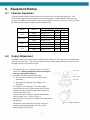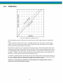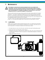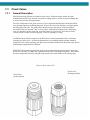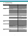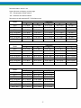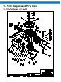
1
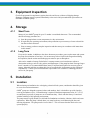
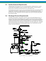
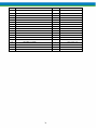
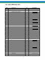
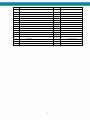
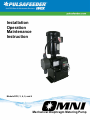
Installation
Operation
Maintenance
Instruction
Models DC2, 3, 4, 5, and 6
Mechanical Diaphragm Metering Pump
Pulsafeeder Factory Service Policy
Should you experience a problem with your Pulsafeeder pump, first consult the troubleshooting guide in
your operation and maintenance manual. If the problem is not covered or cannot be solved, please
contact your local Pulsafeeder Sales Representative or Distributor, or our Technical Services Department
for further assistance.
Trained technicians are available to diagnose your problem and arrange a solution. Solutions may include
purchase of replacement parts or returning the unit to the factory for inspection and repair. All returns
require a Return Authorization number to be issued by Pulsafeeder. Parts purchased to correct a warranty
issue may be credited after an examination of original parts by Pulsafeeder. Warranty parts returned as
defective which test good will be sent back freight collect. No credit will be issued on any replacement
electronic parts.
Any modifications or out-of-warranty repairs will be subject to bench fees and costs associated with
replacement parts.
Safety Considerations:
1. Read and understand all related instructions and documentation before attempting to install or maintain
this equipment
2. Observe all special instructions, notes, and cautions.
3. Act with care and exercise good common sense and judgment during all installation, adjustment, and
maintenance procedures.
4. Ensure that all safety and work procedures and standards that are applicable to your company and facility
are followed during the installation, maintenance, and operation of this equipment.
Revision History:
Rev B (3-1-05)
- Update diagram fig. 10
- Revise text step 11b page 11 diaphragm removal and replacement
- Update all parts diagrams and lists, Section 12
Rev C (9-1-06)
- Update for Kynar (PVDF) heads
- Add model string ID page
- Update KOPkit list with PVDF kits
- Update parts lists with PVDF parts
Rev E (2-2007)
- Update all for introduction of model DC6, SPO address only
- Update materials references to “PTFE”
Rev F (12-2009)
- Update KOPkit list with DC6 KOPkit part numbers
Rev G (8-2010)
- Update Branding
Copyright ©2004, 2006, 2007 Pulsafeeder, Inc. All rights reserved.
Information in this document is subject to change without notice. No part of this publication may be
reproduced, stored in a retrieval system or transmitted in any form or any means electronic or mechanical,
including photocopying and recording for any purpose other than the purchaser’s personal use without the
written permission of Pulsafeeder, Inc.
ii
Table of Contents
1. INTRODUCTION ..................................................................................................................................... 1
2. PRINCIPLES OF OPERATION .................................................................................................................. 1
2.1
Reagent Head Assembly ........................................................................................................ 2
2.2
Control Assembly .................................................................................................................... 2
2.3
Gear Ratio Assembly .............................................................................................................. 2
3. EQUIPMENT INSPECTION ....................................................................................................................... 3
4. STORAGE ……………………………………………………………………………………………………...3
5. INSTALLATION ...................................................................................................................................... 3
5.1
Location .................................................................................................................................... 3
5.2
Piping System .......................................................................................................................... 4
5.3
Suction Pressure Requirements ............................................................................................ 5
5.4
Discharge Pressure Requirements ........................................................................................ 5
6. EQUIPMENT STARTUP ........................................................................................................................... 6
6.1
Fastener Inspection................................................................................................................. 6
6.2
Output Adjustment .................................................................................................................. 6
6.3
Priming the Reagent Head ...................................................................................................... 7
6.4
Calibration ................................................................................................................................ 8
7. M AINTENANCE ...................................................................................................................................... 9
7.1
Lubrication ............................................................................................................................... 9
7.2
Wet End Removal, Inspection, & Reinstallation ................................................................... 10
7.3
Check Valves ........................................................................................................................... 12
7.4
Motor Removal & Reinstallation ............................................................................................ 16
7.5
Gearset Removal ..................................................................................................................... 16
7.6
Gearset Replacement .............................................................................................................. 18
8. REPLACEMENT PARTS .......................................................................................................................... 19
8.1
KOPkit Program ....................................................................................................................... 19
8.2
Ordering KOPkits or Parts ...................................................................................................... 19
iii
8.3
KOPkit numbers by model: .................................................................................................... 20
9. MODEL NUMBER IDENTIFICATION........................................................................................................... 21
10. WET END M ATERIALS REFERENCE ........................................................................................................ 22
11. TROUBLESHOOTING .............................................................................................................................. 23
12. PIPING ACCESSORIES ........................................................................................................................... 25
13. DIMENSIONAL DRAWING........................................................................................................................ 26
14. PARTS DIAGRAMS AND PARTS LISTS ..................................................................................................... 28
14.1
Parts diagram, DC2 and 3 ....................................................................................................... 28
14.2
Bill of Materials, DC2 ............................................................................................................... 29
14.3
Bill of Materials, DC3 ............................................................................................................... 31
14.4
Parts Diagram, DC4, 5, and 6.................................................................................................. 34
14.5
Bill of Materials, DC4 ............................................................................................................... 36
14.6
Bill of Materials, DC5 ............................................................................................................... 38
14.7
Bill of Materials, DC6 ............................................................................................................... 40
iv
1. Introduction
The OMNI® metering pump is positive displacement, mechanically operated reciprocating diaphragm
pump. Each pump consists of a power end and a process end separated by a PTFE faced diaphragm.
Individual pumps will vary in appearance due to various liquid ends and accessories; however, the basic
principles of operation remain the same.
2. Principles Of Operation
Figure 1, reagent head operation
A diaphragm reciprocates at a preset stroke length, displacing an exact volume of process fluid.
Diaphragm retraction causes the product to enter through the suction check valve. Diaphragm advance
causes the discharge of an equal amount of the product through the discharge check valve.
1
2.1
Reagent Head Assembly
The typical reagent head assembly consists of reagent head, diaphragm, and suction and discharge
cartridge check valves. This assembly is the only part of the pump to contact the process liquid;
consequently, maintenance is critical to pump performance.
2.2
Control Assembly
The OMNI® pump incorporates a lost motion style of stroke length adjustment to limit diaphragm
travel during the suction portion of each stroke. The stroke length setting is indicated by a (0% –
100%) scale located on the stroke adjustment assembly.
Stroke length is changed by loosening the locking screw and turning the hand knob. This turns a
mechanism, which limits rearward travel of the diaphragm. Refer to Section 6.2 for further
information.
For automatic flow rate control, users can consider the Pulsafeeder MPC speed based control system,
please contact your local Pulsafeeder dealer or representative for more information.
2.3
Gear Ratio Assembly
OMNI® pumps are driven by an electric motor mounted on the motor adaptor input flange. The
motor drives a set of worm gears that convert rotational speed into torque. They, in turn, power the
eccentric shaft assembly that converts rotary motion into reciprocating motion.
Figure 2, isometric view
2
3. Equipment Inspection
Check all equipment for completeness against the order and for any evidence of shipping damage.
Shortages or damage must be reported immediately to the carrier and your authorized representative or
distributor of OMNI® pumps.
4. Storage
4.1.1
Short Term
Storage of your OMNI® pump for up to 12 months is considered short-term. The recommended
short-term storage procedures are:
a) Store the pump indoors at room temperature in a dry environment.
b) If required by the operating environment, take precautions to prevent entry of water or humid air
into the eccentric enclosure.
c) Prior to startup, perform a complete inspection and then start up in accordance with instructions
in this manual.
4.1.2
Long Term
Every twelve months, in addition to the above short-term procedures, power up the motor and operate
the pump for a minimum of one hour. It is not necessary to have liquid in the reagent head during
this operation, but the suction and discharge ports must be open to atmosphere.
After twelve months of storage, Pulsafeeder’s warranty cannot cover items that are subject to
deterioration with age, such as seals, gaskets, and diaphragms. If the pump has been in storage longer
than 12 months it is recommended that these items be inspected and replaced as necessary prior to
startup. Materials and labor to replace this class of item under this circumstance are the purchaser’s
responsibility. Consult your local Pulsafeeder representative for assistance in obtaining parts and
service for your pump.
5. Installation
5.1
Location
When selecting an installation site or designing a chemical feed system, consideration should be given
to access for routine maintenance.
OMNI® pumps are designed to operate indoors and outdoors, but it is desirable to provide a hood or
covering for outdoor service. External heating is required if ambient temperatures below 0° C (32° F)
are anticipated, especially if pumps are not in continuous duty. Check with the factory if concerned
with the suitability of the operating environment.
The pump must be rigidly bolted to a solid and flat foundation to minimize vibration, which can loosen
connections. When the pump is bolted down, care must be taken to avoid distorting the base and
affecting alignments. The pump must be level within 5°. This will assure that the check valves can
operate properly.
3
5.2
Piping System
1. All systems should include a pressure relief valve on the discharge side, to protect piping and process
equipment, including the pump, from excess process pressures. An external relief valve is
required! There should be no devices capable of restricting flow (such as a valve) located between
the pump and the relief device.
2. Shutoff valves and unions (or flanges) on suction and discharge piping are recommended. This
permits check valve inspection without draining long runs of piping, making periodic maintenance
and inspection easier.
Shutoff valves should be of the same size as connecting pipe. Ball valves are preferred since they
offer minimum flow restriction.
3. Suction systems should include an inlet strainer, if appropriate for the product being pumped. Pump
check valves are susceptible to dirt and other solid contaminants, and any accumulation can cause
malfunction. The strainer should be located between the suction shutoff valve and the pump suction
valve. It must be sized to accommodate the flow rate and the anticipated level of contamination. A
100 mesh screen size is generally recommended.
4. Vacuum/pressure gauges in the suction and discharge lines are helpful in order to check system
operation. Gauges should be fitted with protective shutoff valves for isolation while not in use.
5. Piping weight must not be supported by valve housings or other portions of the reagent head, as the
resulting stresses can cause leaks. If appropriate, provide for thermal expansion and contraction so
that no excess force or moments are applied to the pump.
6. When making process connections, ensure that the check valve assemblies do not rotate as the
threaded connections are secured. It is critical, especially with plastic construction, that the check
valves not be too tight into the reagent head. The threaded connection between the check valve
assembly and the regent head uses on o-ring seal and does not require sealing tape or any other
sealant.
7. In piping assembly, use a sealing compound chemically compatible with the process material. Users
of sealing tape are cautioned to ensure that the entering pipe thread ends are not taped, and that tape is
removed from previously-used threads to the maximum practical extent prior to re-use. Both new and
existing piping should be cleaned, preferably by flushing with a clean liquid (compatible with process
material) and blown out with air, prior to connection to the pump. Debris from the piping system that
prevents proper check valve operation is a common startup issue.
8. Note that for pumps which utilize cartridge-type check valve assemblies, no thread tape or sealant is
required on the threads which secure the cartridge assembly to the pump reagent head. This area is
sealed with o-rings integral to the cartridge. Sealant on these threads can actually degrade sealing
capability.
4
5.3
Suction Pressure Requirements
Although OMNI® metering pumps have some suction lift capability, a flooded suction (i.e., suction
pressure higher than atmospheric pressure) is preferable whenever possible. The pump should be
located as close as possible to the suction side reservoir or fluid supply source.
For fluid with a vapor pressure of 5 psia or less (at operating temperature) the wet suction lift capability
is approximately ten (10) feet. If this requirement is not met, the pump will not provide reliable,
accurate flow. In suction lift conditions, the use of a foot valve is recommended at the lowest point of
the pickup tube or pipe. Pumps under suction lift conditions may require some liquid priming before
they will operate reliably.
5.4
Discharge Pressure Requirements
All OMNI® metering pumps are designed for continuous service at the rated discharge pressure. If
system suction pressure exceeds discharge pressure (a condition sometimes described as “pumping
downhill”), flow would be generated (siphoning) in addition to that caused by the pump. This results in
a reduction in accuracy and loss of control over the metering process. To prevent this flow-through
condition, the discharge pressure must exceed suction pressure by at least 0.35 Bar (5 psi). This can be
achieved where necessary by the installation of a backpressure valve in the discharge line. Conditions
where the actual discharge pressure exceeds the pump’s rating are to be avoided as they will cause
damage to the pump components.
Figure 3, sample system configuration
5
6. Equipment Startup
6.1
Fastener Inspection
All pump fasteners should be checked prior to pump operation, and occasionally during use. This
would include reagent head mounting bolts, motor mounting bolts, and the hardware that secures the
pump to its foundation. Most hardware can be checked simply to ensure it is not loose. However, utilize
the following values when checking reagent head bolt torque:
Model
DC2
DC3 and 4
DC5
DC6
6.2
Material
Plastic
Metal
Plastic
Metal
Plastic
Metal
Plastic
Metal
Reagent Head Bolt Torque
# Bolts and size
N-m
In. - Lbs
(4) M6 * 1.0
3.39
30
(4) M6 * 1.0
3.39
30
(4) M8 * 1.25
6.77
60
(4) M8 * 1.25
6.77
60
(6) M8 * 1.25
8.46
75
(6) M8 * 1.25
8.46
75
(6) M8 * 1.25
8.46
75
(6) M8 * 1.25
8.46
75
Output Adjustment
All OMNI® pumps have a hand wheel for manual stroke adjustment. The hand wheel can be adjusted to
any point from 0 to 100%. This value represents the stroke length setting and therefore the flow rate of
the pump relative to its maximum output.
1. Turn the red lock screw counterclockwise to release the
stroke lock. Making adjustments without releasing the
lock may damage the mechanism.
2. Adjust the hand wheel to the desired output.
a) The stroke barrel indicates stroke length in 20%
increments.
b) The hand wheel indicates stroke length in 1%
increments.
For example, to set the pump to 75% stroke length,
(starting from the factory default setting of 0%) turn the
hand wheel counter clockwise until he 60% indicator is
visible on the stroke barrel.
Continue the counter clockwise rotation until the hand
wheel indicator is at 15. Refer to Figure 4.
3. Turn the lock screw clockwise to lock the stroke adjustment
into position.
Adjustments can be made while the pump is at rest or
operating, although adjustments are easier to make
while the pump is in operation.
6
Figure 4, stroke adjustment
6.3
Priming the Reagent Head
1. When handling process liquids, follow all applicable personal and facility safety guidelines.
2. Ensure that the pump is ready for operation and that all process connections are secure.
3. Open the suction and discharge line shutoff valves.
4. If the piping system design and the storage tank are such that the product flows due to gravity through
the pump, reduce the discharge pressure and the system will self prime when the pump is started. In
the event the discharge line contains a significant amount of pressurized air or other gas, it may be
necessary to lower the discharge pressure to enable the pump to self-prime.
5. If the installation involves a suction lift, it may be necessary to prime the reagent head and suction
line. Operate the pump as in step 4 above, many times the pump will be capable of self priming. If it
does not begin to pump, remove the discharge valve assembly. Carefully fill the reagent head
through the discharge valve port with process (or compatible) liquid, and then reinstall the check
valve.
6. Start the pump at the zero stroke length setting and slowly increase the setting to 100 to prime the
pump. If this does not work, it will be necessary to fill the suction line.
7. Filling of the suction line will necessitate the use of a foot valve or similar device at the end of the
suction line so that liquid can be maintained above the reservoir level. Remove the suction valve
assembly, fill the line, replace the suction valve, then remove the discharge valve assembly and fill
the reagent head as described in Step (3) above. The pump will now self-prime when started up per
step (4) above. Use appropriate precautions if handling process fluid. Ensure that any other fluid
used for priming is compatible with the product that will be pumped.
Figure 5, process flow
7
6.4
Calibration
Figure 6, sample flow calibration curve
All metering pumps must be calibrated to accurately specify stroke length settings for required flow
rates.
A typical calibration chart is shown above. Although output is linear with respect to stroke length
setting, an increase in discharge pressure decreases output uniformly, describing a series of parallel
lines, one for each pressure (only two are shown).
The theoretical output flow rate at atmospheric discharge pressure is based on the displacement of the
diaphragm, stroke length and the stroking rate of the pump. With increasing discharge pressure there is
a corresponding decrease in output flow. Pumps are rated for a certain flow at a rated pressure (check
nameplate). Whenever possible, calibration should be performed under actual process conditions (i.e.,
the same or a similar process liquid at system operating pressure).
To construct a calibration chart, measure the flow rate several times at three or more stroke settings (i.e.,
25, 50, 75, and 100), plot these values on linear graph paper, and draw a best-fit line through the points.
For stable conditions, this line should predict settings to attain required outputs.
All users are encouraged to test the flow rate of their pump once installed in their system, to
ensure best accuracy and reliable operation.
8
7. Maintenance
BEFORE PERFORMING ANY MAINTENANCE REQUIRING REAGENT HEAD OR VALVE (WET END)
DISASSEMBLY, BE SURE TO RELIEVE PRESSURE FROM THE PIPING SYSTEM AND, WHERE
HAZARDOUS PROCESS MATERIALS ARE INVOLVED, RENDER THE PUMP SAFE TO PERSONNEL
AND THE ENVIRONMENT BY CLEANING AND CHEMICALLY NEUTRALIZING AS APPROPRIATE.
WEAR PROTECTIVE CLOTHING AND EQUIPMENT AS APPROPRIATE.
Accurate records from the early stages of pump operation will indicate the type and levels of required
maintenance. A preventative maintenance program based on such records will minimize operational
problems. It is not possible to forecast the lives of wetted parts such as diaphragms and check valves.
Since corrosion rates and operational conditions affect functional material life, each metering pump must
be considered according to its particular service conditions.
The OMNI® KOPkit will contain all replacement parts normally used in a preventative maintenance
program. It is recommended that KOPkits and PULSAlube grease be kept available at all times.
7.1
Lubrication
OMNI® pumps are supplied completely lubricated from the factory. For optimum pump performance
under normal conditions, gear grease should be redistributed every 1500 hours. For severe service in
extreme temperatures or very dirty environments, this interval may be shorter.
1. Disconnect the power source to the drive motor, and relieve all pressure from the piping system.
2. Remove the side cover from the pump. Refer to Figure 7.
3. Redistribute grease onto gear and worm teeth. On DC2 and 3 pumps, force grease into the hole in the
end of the gear shaft using a screwdriver or putty knife. Primary lubrication points are called out in
Figure 7, below.
4. Replace the side gasket and cover.
1.
9
Figure 7, gearset lubrication points
7.2
Wet End Removal, Inspection, & Reinstallation
IF THE DIAPHRAGM HAS FAILED, PROCESS FLUID MAY HAVE CONTAMINATED THE PUMP
ECCENTRIC HOUSING (ALTHOUGH NORMALLY, ANY PROCESS FLUID BEHIND A FAILED
DIAPHRAGM WOULD PASS THROUGH THE BOTTOM DRAIN HOLE). HANDLE WITH APPROPRIATE
CARE.
Figure 8, wet end components
OMNI® diaphragms do not have a specific cycle life; however, the accumulation of foreign material
or debris sufficient to deform the diaphragm can eventually cause failure. Failure can also occur as a
result of system over pressure or chemical attack. Periodic diaphragm inspection and replacement are
recommended. Each user should perform regular inspections to determine the replacement interval
that is appropriate to their system conditions.
10
7.2.1
Diaphragm Removal & Reinstallation
1. Adjust the stroke setting to 50% and disconnect the power source to the drive motor.
2. Relieve all pressure from the piping system.
Take all precautions described under the WARNING on page 9, Section 7 to prevent environmental
damage and exposure of personnel to hazardous materials.
3. Close the inlet and outlet shutoff valves.
4. Place a pan underneath the pump head adaptor to catch any liquid leakage.
5. Disconnect piping to the reagent head and drain any process liquid, following material safety
precautions described.
6. Remove all but one top reagent head bolt. Product will leak out between the pump head adaptor and
reagent head as the bolts are loosened.
7. Tilt the head and pour out any liquids retained by the check valves into a suitable container,
continuing to follow safety precautions as appropriate.
8. Remove the final bolt and rinse or clean the reagent head with an appropriate material.
9. Remove the diaphragm by turning it counter-clockwise.
10. Inspect the diaphragm. The diaphragm must be replaced if it is cracked, separated, or obviously
damaged.
11. Install the diaphragm.
a) Ensure that the critical sealing areas of diaphragm, reagent head, and pump head are clean and
free of debris.
b) Lubricate the elastomer side of the diaphragm liberally, where it is in contact against the pump
head and deflection plate. Use a silicone grease or silicone-based o-ring lubricant.
12. Thread the diaphragm (clockwise) fully onto the shaft.
When reinstalling a used diaphragm it is not necessary to maintain the previous orientation relative to
the reagent head or pump head hole pattern.
13. Install the reagent head bolts and tighten in an alternating pattern to ensure an even seating force.
Torque to the values recommended in Section 6.1.
14. Re-prime the pump following the procedure outlined in Section 6.3.
11
7.3
7.3.1
Check Valves
General Description
Most fluid metering problems are related to check valves. Problems usually stem from solids
accumulation between valve and seat, corrosion of seating surfaces, erosion, or physical damage due
to wear or the presence of foreign objects.
The valve incorporates a ball, guide, and seat. Flow in the unchecked direction lifts the ball off the
seat, allowing liquid to pass through the guide. Reverse flow forces the ball down, sealing it against
the sharp edge of the seat. The guide permits the ball to rotate but restricts vertical and lateral
movement in order to minimize “slip” or reverse flow. Ball rotation prolongs life by distributing
wear over the entire surface of the ball. Since ball return is by gravity, the valve must be in the
vertical position in order to function properly. Parts are sealed by “O”-rings.
All OMNI models with the exception of the DC5 and 6 in metal construction utilize a convenient
cartridge-type check valve. All check components are pre-assembled and the cartridge should be
replaced as a unit. When replacing, note that valves are marked with the flow direction, as the suction
and discharge configurations are different.
OMNI DC5 and 6 models supplied with metal (316ss) reagent head construction utilize a multi-part
check valve assembly, secured to the reagent head with a tie-bar clamping arrangement. These utilize
the same components (seat, ball, and guide) and operate in the same manner as the cartridge type.
Figure 9, check valves, DC2
Check Valve
Discharge Position
Check Valve
Suction Position
Figure 9, check valves DC2
12
Check Valve
Suction Position
Check Valve
Discharge Position
Figure 10, check valves, DC3 and DC 4
Check Valve
Suction Position
Check Valve
Discharge Position
Figure 11, check valves, DC5 and DC6 plastic construction
13
7.3.2
Check Valve Removal & Reinstallation, Cartridge type
Valving that is of the cartridge design is intended to be replaced as an assembly.
15. Disconnect the power source to the drive motor.
16. Relieve all pressure from the piping system.
17. Take all precautions necessary to prevent contamination to the environment and personnel exposure
to hazardous materials.
18. Close the inlet and outlet shutoff valves.
19. Disconnect the suction piping at the installed union near the suction port.
20. Loosen and remove the suction valve cartridge slowly to drain any liquid from the reagent head.
21. Disconnect the discharge piping at the installed union near the discharge port.
22. Loosen and remove the discharge valve cartridge slowly to drain any trapped liquid.
23. Reinstall both new valve assemblies, taking care to ensure that they are in the correct ports.
Lettering on the side of each valve should be right side up when assembled to the pump. Each valve
assembly should also have an arrow, which should indicate direction of flow (upwards). Do not coat
the threads of the cartridge vale with a pipe sealant. Each valve cartridge should be tightened only
until the o-ring seal makes good contact with the reagent head surface. Over-tightening will cause
damage and lead to leaks
24. Reinstall both suction and discharge piping. Secure the cartridge while making your external
connections to prevent rotating the cartridge and over-tightening it into the pump.
7.3.3
Check Valve Removal & Reinstallation, Tie-bar type
1. Disconnect the power source to the drive motor.
2. Relieve all pressure from the piping system.
3. Take all precautions necessary to prevent contamination to the environment and personnel exposure
to hazardous materials.
4. Close the inlet and outlet shutoff valves.
5. Loosen the suction valve tie-bar bolts (4) and spring the suction piping slightly away from the head,
allowing liquid to drain. It may be necessary to loosen a union or flange.
6. Remove the suction check valve assembly by sliding it towards you, holding it together as a unit.
Note carefully the position of the component parts, to assist in re-assembly.
7. Loosen the discharge valve tie-bar bolts (4) and spring the discharge piping slightly away from the
head, allowing liquid to drain. It may be necessary to loosen a union or flange.
8. Remove the discharge check valve assembly by sliding it towards you, holding it together as a unit.
Note carefully the position of the component parts, to assist in re-assembly.
9. Disassemble both valves and check components for wear or damage. The seats should have a sharp
edge and be free from dents or nicks. Hold a ball firmly against the seat in front of a bright light and
inspect for fit, observation of light between the ball and seat is cause for replacement.
10. Reassemble both valves using new parts as required. Sealing o-rings should always be replaced.
11. Replace both valve assemblies onto the pump, taking care to ensure they are oriented correctly, with
the balls above the seats, and the seats oriented with the sharp edge up and the chamfered edge down.
14
Inserting the check valve assmbly into the pump in the wrong directiom, or having the check seat
upside down, will prevent proper seals at the o-rings, decrease pump performance, and can cause
damage to the diaphragm.
12. Carefully make sure that the check assemblies are in proper position, and tighten the four tie-bar
bolts, using a star pattern, to a torque of 6 Ft-lbs (8 N-m).
13. Retighten any unions, flanges, or other process connections that may have been loosened previously.
Figure 12, DC5 and 6 check valves, metal construction
15
7.4
Motor Removal & Reinstallation
1. Disconnect the power source to the drive motor.
2. Disconnect the motor wiring from the motor.
3. Remove the four bolts retaining the motor to the motor adaptor.
The motor shaft fits into a bore on the pump input shaft.
4. Slide the motor shaft out of the pump input shaft.
Be careful not to lift the pump input shaft up out of the pump.
5. Apply a lubricant such as Loctite™ Silver Grade® Anti-seize paste
(or similar) to the motor shaft and key before reassembling..
6. Reinstall the motor by sliding the motor shaft into the pump input
shaft.
7. Insert and tighten the four bolts removed in step 3.
8. Reconnect the motor wiring to the motor.
9. Connect power to the drive motor.
Figure 13, motor mounting
Motor rotation must be wired for CW rotation, as viewed from the top of the motor, as noted by the
arrow on the top of the pump housing.
7.5
Gearset Removal
Gearset diagram is on following page
1.
2.
3.
4.
Disconnect power source and wiring from the motor.
Set stroke adjustment to zero.
Remove motor from the pump (refer to Section 7.4).
Remove the four socket head screws (Item 1) that attach the motor adaptor (Item 2) to the
pump housing and remove the adaptor.
5. Loosen and remove the Hex Head Bolts (Item 5), and remove the pump side cover (Item 6)
and gasket (Item 7).
6. Remove the Worm Shaft Assembly (item 4) by carefully pulling it straight up out of the
pump housing. On DC2 and DC3 models, be careful not to lose the lower thrust bearing
and washers (items 11 and 12).
16
Figure 14, gearset components
7. Loosen the set screw (Item 9) on the worm gear (Item 8) and remove it along with its
shaft key (Item 10).
If you have the DC2 or 3 models go to step 8. If you have the DC4, 5, or 6 models go to
step 9.
8. Remove the Thrust Washers and Bearing
(Item 11 & 12) from the housing.
If the Thrust Washers show signs of
excessive wear or scoring, replace them
during re-assembly.
9. Clean grease from the gear cavity.
10. Examine the Worm Shaft Grease Seal
(Item 3) in the pump housing on the DC
2 and 3 model or in the motor adaptor on
the DC 4, 5, and 6 models.
If the Grease Seal shows excessive wear
or damage, replace it during re-assembly.
Figure 15, worm shaft
17
7.6
Gearset Replacement
1. Apply PULSAlube grease # NP980006-000 to both sides of the thrust washer and install onto the
eccentric shaft.
On the DC4, 5, and 6 models, the washer fits into a shallow counter-bore.
2. Assemble Worm Gear (Item 8) and key (Item 10) to the eccentric shaft. Do not tighten the setscrew
yet.
3. Thread the M6-1.0 screw into the threaded hole in the end of the eccentric shaft. Tighten the Worm
Gear set screw while simultaneously pulling on the screw in the end of the shaft in order to eliminate
any endplay in the eccentric shaft.
4. Rotate the Worm Gear
It should turn easily with no perceptible endplay.
5. Remove the screw that was inserted in the shaft in step 3.
6. Assemble and install the worm shaft assembly
a) If you have a DC2 or 3 model:
Apply PULSAlube grease # NP980006-000 to the two lips of the worm shaft seal.
Apply PULSAlube grease # NP980006-000 to the small end of the worm shaft.
Carefully insert the worm shaft into the pump housing.
Assemble the lower thrust bearing (with a washer on each side) into the shallow counter bore in
the bottom of the housing cavity.
Fit the shaft into the bearing in the housing.
b) If you have a DC4, 5, or 6 model:
Apply PULSAlube grease # NP980006-000 to the small end of the worm shaft.
Insert the worm shaft into the pump housing, fitting the end of the shaft into the bearing in the
housing.
Apply PULSAlube grease # NP980006-000 to the two lips of the seal.
Assemble the adapter to the pump housing while carefully slipping the seal over the worm shaft.
7. Fill the gear cavity completely with PULSAlube grease # NP980006-000 and reassemble the pump
side cover and gasket.
8. Reassemble the motor to the pump. Verify that motor rotation is clockwise when viewed from the
top.
9. Reinstall the pump in the system and restart the pump (refer to Section 6 – Startup).
18
8. Replacement Parts
8.1
KOPkit Program
OMNI® KOPkits contain all replacement parts normally used in a preventative maintenance program.
(PULSAlube grease is also available separately for preventative maintenance programs. Refer to
Section 6 – Equipment Startup). There is a specific KOPkit for every OMNI® pump model. Each
KOPkit is vacuum-packed for extended storage. All OMNI® pumps have the KOPkit number identified
on the pump nameplate and Pulsafeeder order documents. KOPkits can also be selected from the
technical data sheet shipped with the pump or by a Pulsafeeder representative. A list of the OMNI
KOPkit numbers can also be found on the next page. The kit is identified by the model number of the
pump, the wetted end material, and the process connection thread type. For models with tie-bar type
check valves, the appropriate components (check valve balls, seats, and o-rings) are supplied instead of
the cartridges pictured.
Figure 16, KOPkit parts
8.2
Ordering KOPkits or Parts
When ordering replacement parts always specify:
•
•
Pump model and serial number (from pump nameplate), e.g., Model No. (DC-2) with Serial No.
F406365-3.
Part number and description from the OMNI® parts list. Include the three-character suffix. (Note:
OMNI part numbers begin either with the letters NP, or the letter W, e.g., NP170001-THY or
W210221-001.)
19
8.3
KOPkit numbers by model:
Pump Model
DC2
Wetted Material
PVDF
Connection Type
NPT
KOPkit number
NLK020FP
DC3 or DC4
PVDF
NPT
NLK040FP
DC3 or DC4
PVDF
ISO 7-1
NLK040FB
DC5
PVDF
NPT
NLK050FP
DC5
PVDF
ISO 7-1
NLK050FB
DC6
PVDF
NPT
NLK060FP
DC6
PVDF
ISO 7-1
NLK060FB
DC7
PVDF
n/a
NLK070FX
DC5
Polypropylene
NPT
NLK050PP
DC5
Polypropylene
ISO 7-1
NLK050PB
DC6
Polypropylene
NPT
NLK060PP
DC6
Polypropylene
ISO 7-1
NLK060PB
DC7
Polypropylene
n/a
NLK070PX
DC2
316
NPT
NLK020AP
DC3 or DC4
316
NPT
NLK040AP
DC3 or DC4
316
ISO 7-1
NLK040AB
DC5
316
NPT
NLK050AP
DC5
316
ISO 7-1
NLK050AB
DC6
316
NPT
NLK060AP
DC6
316
ISO 7-1
NLK060AB
NPT
NLK060HX ( 1 )
ISO 7-1
NLK060HX ( 1 )
(2)
DC6
HSO
DC6
HSO ( 2 )
NOTES:
(1) “HSO” construction refers to the recommended materials for handling Sulfuric Acid at high
concentrations (above 95%). This configuration consists of 316ss for the reagent head, the
valve guide, and the process connection. Alloy-20 is supplied for the check valve seats,
and Hastelloy-C is supplied for the check valve balls. HS0 configuration is supplied only
as a KOPkit and not as an original pump configuration.
(2) PVC wet end material has been discontinued, use PVDF (Kynar®) parts as a direct
replacement for these pumps.
(3) DC7 model is covered in a separate publication
20
9. Model Number Identification
Position
Sample
1 and 2
DC
3 and 4
3B
Specifies
Options
DC = OMNI model pump
Size/Flow
2 / 3 / 4 / 5 / 6 – diaphragm diameter
A / B / C / D – stroking rate
See sales literature for flow/pressure ratings
5
X
6
F
7
P
8
-*
9
Option *
MPC control
M – indicates supplied with MPC controller
10
Option *
Input voltage
1 – 115V 60 Hz
2 – 230V 60 Hz
3 – 110V 50 Hz
4 – 220V 50 Hz
11
Option *
Remote cable
X – standard length remote at pump
C – extended cable length
12
Option *
Language
Motor frame
and size
1 – ½ Hp, 1 pH 115/230V, 71 frame
2 – ½ Hp, 1 pH, 115/230V, 56 frame
3 – ½ Hp, 3 pH, 230/380V, 71 frame
4 – ½ Hp, 3 pH, 230/380/460V, 56 frame
5 – MPC control with 56 frame motor
6 – MPC control, NO motor, 56 frame
7 – MPC control with 71 frame motor
8 – MPC control, NO motor, 71 frame
X – no motor, set up for 56 frame
Y – no motor, set up for 71 frame
Wetted materials F – PVDF, PTFE o-rings, ceramic ball
E – PVC (note - obsolete)
A – 316ss, PTFE o-rings
P - Polypropylene, DC 5 and 6 only
Connections
P – NPT
B – ISO 7-1 (not available on DC2)
position 8 is a dash
E – English
F - French
S - Spanish
G - German
* - If no MPC controller is ordered, the model string ends at position 7. Positions 8 through 12 are
not entered for a pump without the MPC.
21
10. Wet End Materials Reference
Wet End
Configuration
PVDF
®
(Kynar )
Model
Connection
DC2
DC3
DC4
DC5
DC6
1/4" NPT
DC7
PP
(Polypropylene)
DC2
DC3
DC4
DC5
DC6
DC7
SS
(316)
DC2
DC3
DC4
DC5
DC6
DC7
Head
Guide
1/2" NPT or ISO 7-1
1" NPT or ISO 7-1
Sealing
O-rings
PTFE
PVDF
PVDF
1 1/2" NPT & ANSI
Flange and
1 1/2" DIN40 Flange
®
Viton
Seat Oring
PVDF
n/a
PVDF (oring seat)
Viton
PP
n/a
PP (o-ring
seat)
Viton
®
(1)
n/a
1" NPT or I ISO 7-1
PTFE
PP
PP
Ceramic
Viton
1/4" NPT
1/2" NPT or ISO 7-1
Seats
Ceramic
n/a
1 1/2" NPT & ANSI
Flange and
1 1/2" DIN40 Flange
Balls
SS
SS
PTFE
Ceramic
PTFE
SS
SS
1" NPT or ISO 7-1
n/a
n/a
(1) DC7 check valve seats incorporate an o-ring seal
DC7 model is covered in a separate publication
n/a = materials not available in this pump size or component not used on this model
22
®
(1)
n/a
11. Troubleshooting
Difficulty
Pump does not start
No delivery
Probable Cause
Faulty power source.
Blown fuse, circuit breaker.
Broken wire.
Wired improperly.
Process piping blockage.
Motor not running.
Supply tank empty.
Lines clogged.
Closed line valves.
Ball check valves held open with solids.
Vapor lock, cavitation.
Prime lost.
Strainer clogged.
Low delivery
Stroke adjustment set at zero.
Motor speed too low
Check valves worn or dirty
Calibration system error
Product viscosity too high
Delivery gradually
drops.
Delivery erratic.
Delivery higher than
rated.
Product cavitating
Check valve leakage.
Leak in suction line.
Strainer fouled.
Product change.
Supply tank vent plugged.
Leak in suction line.
Product cavitating.
Entrained air or gas in product.
Motor speed erratic.
Fouled check valves.
Inadequate backpressure
Suction pressure higher than discharge
pressure.
Back pressure valve set too low.
Back pressure valve leaks.
23
Remedy
Check power source.
Replace - eliminate overload.
Locate and repair.
Check diagram.
Open valves, clear other obstructions.
Check power source. Check wiring
diagram (see above).
Fill tank.
Clean and flush.
Open valves.
Clean – inspect, flush with clear fluid.
Increase suction pressure.
Re-prime, check for leak.
Remove and clean. Replace screen if
necessary.
Increase stroke length setting.
Check voltages, frequency, wiring, and
terminal connections. Check nameplate
vs. Specifications.
Clean, replace if damaged
Evaluate and correct
Lower viscosity by increasing product
temperature or dilution. Increase pump
and/or piping size
Increase suction pressure.
Clean, replace if damaged.
Locate and correct.
Clean or replace screen.
Check viscosity and other variables.
Unplug vent.
Locate and correct.
Increase suction pressure.
Consult factory for suggested venting.
Check voltage and frequency.
Clean, replace if necessary.
Increase discharge pressure to obtain a
minimum pressure difference of 5 pis
from suction to discharge
Install backpressure valve or consult
factory for piping recommendations.
Increase setting.
Repair, clean, or replace.
Difficulty
Noisy gearing,
knocking
Probable Cause
Discharge pressure too high.
Water hammer.
Stroke length at partial setting.
Piping noisy.
Low grease level.
Pipe size too small.
Motor overheats.
Pipe runs too long.
Pulsation dampener inoperative or
flooded.
No surge chamber or dampener used.
Pump overloaded.
High or low voltage.
Loose wire.
Incorrect motor wiring
24
Remedy
Reduce pressure.
Install pulsation dampener.
Some operating noise is characteristic of
lost motion pumps.
Add or replace grease.
Increase size of piping - install pulsation
dampener.
Install pulsation dampener in line.
Refill with air or inert gas. Inspect and
replace diaphragm and recharge.
Install pulsation dampeners.
Check operating conditions against pump
design. Verify discharge pressure
Check power source.
Trace and correct.
Verify and correct
12. Piping Accessories
Pressure Relief Valves
Pressure relief valves are designed to protect chemical feed systems from damage that may be caused by
defective equipment or a blockage in the discharge line. These valves function to limit the pressure
downstream of the pump. Field adjust the pressure relief valve to operate when the discharge pressure
exceeds operating pressure by 10-15%. Pressure relief valve should always be adjusted to a setting below
the maximum rated pressure of the pump. No potentially restrictive components, such as a valve, should
be installed between the pump discharge and the PRV.
Diaphragm Backpressure Valve
A diaphragm backpressure valve creates constant back pressure. A PTFE or PTFE-faced diaphragm
offers maximum chemical protection and service life, and seals spring and bonnet from product.
Be sure to install with fluid flow in direction of arrow on valve body.
Pulsation Dampener
A pulsation dampener is a pneumatically charged diaphragm-type chamber that intermittently stores
hydraulic energy. Used on the inlet, it can improve NPSHA (Net Positive Suction Head available)
characteristics of the suction piping system. On the discharge line it will reduce discharge pressure and
pulsating flow variations.
25
13. Dimensional Drawing
Letters reference dimensional table on next page
26
Dimension table in inches / mm
Letter references to diagram, previous page
“PP” = Polypropylene wetted material
“SS” = Stainless steel wetted material
Dimensions are with standard IEC 71 B14 frame motor
DC2
A
1.0 / 25.4
B
0.7 / 18.0
Dimension
C
6.9 / 175.3
D
4.5 / 113.5
E
1.5 / 38.1
DC3
1.0 / 25.4
0.7 / 18.0
6.9 / 175.3
4.5 / 113.5
1.5 / 38.1
DC4
2.0 / 50.8
0.9 / 22.4
7.6 / 193.0
5.1 / 130.2
1.8 / 44.5
DC5 – PP/PVDF
2.0 / 50.8
0.9 / 22.4
7.6 / 193.0
5.1 / 130.2
1.8 / 44.5
DC5 – SS
2.0 / 50.8
0.9 / 22.4
7.6 / 193.0
5.1 / 130.2
1.8 / 44.5
DC6 – PP/PVDF
2.0 / 50.8
0.9 / 22.4
7.6 / 193.0
5.1 / 130.2
1.8 / 44.5
DC6 - SS
2.0 / 50.8
0.9 / 22.4
7.6 / 193.0
5.1 / 130.2
1.8 / 44.5
G
7.4 / 188.7
Dimension
H
13.6 / 347.6
I
DC2
F
2.9 / 72.4
1.8 / 46.7
J
5.7 / 145.3
DC3
3.3 / 83.6
7.4 / 188.7
14.6 / 370.2
1.8 / 46.7
5.7 / 145.3
DC4
3.4 / 85.5
8.4 / 213.9
15.4 / 392.4
2.5 / 63.5
6.9 / 175.5
DC5 – PP/PVDF
3.6 / 90.4
8.4 / 213.9
15.8 / 402.0
2.5 / 63.5
6.9 / 175.5
DC5 – SS
3.6 / 90.4
8.4 / 213.9
15.8 / 402.0
2.5 / 63.5
6.9 / 175.5
DC6 – PP/PVDF
3.6 / 90.4
8.4 / 213.9
15.8 / 402.0
2.5 / 63.5
6.9 / 175.5
DC6 - SS
3.6 / 90.4
8.4 / 213.9
15.8 / 402.0
2.5 / 63.5
6.9 / 175.5
DC2
K
14.5 / 367.5
L
7.7 / 196.3
Dimension
M
3.9 / 98.2
DC3
14.5 / 367.5
8.9 / 226.1
4.5 / 113.0
DC4
15.7 / 397.8
8.9 / 226.1
4.5 / 113.0
DC5 – PP/PVDF
15.7 / 397.8
13.8 / 350.5
6.9 / 175.3
DC5 – SS
15.7 / 397.8
12.6 / 320.0
6.3 / 160.0
DC6 – PP/PVDF
15.7 / 397.8
15.3 / 387.3
7.6 / 193.7
DC6 – SS
15.7 / 397.8
14.1 / 356.9
7.1 / 178.5
Model
Model
Model
27
14. Parts Diagrams and Parts Lists
14.1 Parts diagram, DC2 and 3
28
14.2 Bill of Materials, DC2
ITEM
1
DESCRIPTION
SUPPORT PLATE
QTY
1
PART NUMBER
NP140054-BRS
2
DIAPHRAGM
1
NP170030-THY
3
REAGENT HEAD PVDF
1
NP160076-PVD
3
REAGENT HEAD PVC (obsolete)
1
NP160054-PVC
3
REAGENT HEAD 316
1
NP160054-316
4
BOLT
4
NP990420-188
5
FLT WASHER
4
NP991017-188
6
DC2 SPOOL ADAPTOR
1
NP140067-ALU
7
VLV ASSY PVDF
NPT
DISCHARGE
1
L3200TC4-PVD
7
VLV ASSY PVC
NPT
DISCHARGE (obs)
1
L3200TC4-PVC
7
VLV ASSY 316
NPT
DISCHARGE
1
L3200TC4-316
8
VLV ASSY PVDF
NPT
SUCTION
1
L3100TC4-PVD
8
VLV ASSY PVC
NPT
SUCTION (obs)
1
L3100TC4-PVC
8
VLV ASSY 316
NPT
SUCTION
1
L3100TC4-316
9
RETURN SPRING
1
NP430033-000
10
BOTTOM COVER
1
NP250084-000
11
BOTTOM COVER SCREW
4
NP992216-STL
12
STRADDLE ASSEMBLY
1
NP410066-000
13
BEARING
1
NP400037-000
14
ECCENTRIC
1
NP070022-000
15
BEARING
1
NP400041-000
16
THRUST WASHER
2
NP470033-000
17
WORM
11:1
1
W206961-000
17
WORM
20:1
1
W056965-000
40:1
1
W047022-000
1
W770013-000
17
WORM
18
SCREW
19
GASKET
1
NP460045-000
20
SIDE COVER
1
NP250060-STL
21
BOLT
4
NP990414-188
22
GEAR
11:1
1
W206446-011
22
GEAR
20:1
1
W206446-020
22
GEAR
40:1
1
W206446-040
23
THRUST WASHER
1
NP470029-000
24
ECCENTRIC SHAFT
1
NP410054-000
25
BEARING
2
NP400039-000
26
STRK ADJ ASSEMBLY
1
NP260013-000
27
KNOB
1
NP260001-GPC
28
KNOB COVER
1
NP250061-000
29
SCREW
1
W771001-010
30
LABEL
1
NP550084-000
31
WASHER
1
W771006-STL
32
MOTOR ADAPT ASSY 56C
1
NP490030-000
32
MOTOR ADAPT ASSY 71
1
NP490029-000
33
WORM SHAFT ASSY 56C
1
NP060031-A00
33
WORM SHAFT ASSY IEC71
1
NP060031-D00
29
34
DC2/3 GEARBOX
1
NP010024-ALU
35
NAME TAG
1
NP550130-000
36
NAME TAG SCREW
4
W771000-188
38
SET SCREW
2
W771004-022
39
NEEDLE BEARING
1
NP400046-000
40
KEY-WORM GEAR
1
W773097-004
41
ECCENTRIC SPACER
1
NP470031-000
42
GASKET
1
NP460047-000
43
SCREW
2
NP990008-STA
44
OIL SEAL
1
NP450029-000
45
PIPE PLUG
1
W772565-STL
46
WASHER
1
W774034-STL
47
SPOOL ADAPTOR BOLT
4
W770534-STL
48
SPOOL ADAPTOR WASHER
4
NP991018-188
49
RETAINING RING 71 FRAME
1
NP999041-000
50
RETAINER 71 FRAME
1
NP470041-STL
50
RETAINER 56C FRAME
1
NP410075-000
51
RETAINING RING 71 FRAME
1
NP999042-000
51
RETAINING RING 56C FRAME
1
NP999032-000
30
14.3 Bill of Materials, DC3
ITEM
1
DESCRIPTION
SUPPORT PLATE
QTY
1
PART NUMBER
NP140055-BRS
2
DIAPHRAGM
1
NP170031-THY
3
REAGENT HEAD PVDF
1
NP160077-PVD
3
REAGENT HEAD PVC (obsolete)
1
NP160055-PVC
3
REAGENT HEAD 316
1
NP160055-316
4
BOLT
4
NP990436-188
5
FLT WASHER
4
NP991018-188
6
DC3 SPOOL ADAPTOR
1
NP140068-ALU
7
VALVE DISCHARGE
PVDF
ISO 7-1
1
NP32BVC8-PVD
7
VALVE, DISCHARGE,
316,
ISO 7-1
1
NP32BAA8-316
7
VALVE, DISCHARGE,
PVC,
ISO 7-1 (obs)
1
NP32BVC8-PVC
7
VALVE DISCHARGE
PVDF
NPT
1
NP32PVD8-PVD
7
VALVE, DISCHARGE,
316,
NPT
1
NP32PAA8-316
7
VALVE, DISCHARGE,
PVC,
NPT (obs)
1
NP32PVC8-PVC
8
VALVE, SUCTION,
PVDF
ISO 7-1
1
NP31BVC8-PVD
8
VALVE, SUCTION,
316,
ISO 7-1
1
NP31BAA8-316
8
VALVE, SUCTION,
PVC,
ISO 7-1 (obs)
1
NP31BVC8-PVC
8
VALVE , SUCTION,
PVDF
NPT
1
NP31PVD8-PVD
8
VALVE, SUCTION,
316,
NPT
1
NP31PAA8-316
8
VALVE, SUCTION,
PVC,
NPT (obs)
1
NP31PVC8-PVC
9
RETURN SPRING
1
NP430033-000
10
BOTTOM COVER
1
NP250084-000
11
BOTTOM COVER SCREW
4
NP992216-STL
12
STRADDLE ASSEMBLY
1
NP410066-000
13
BEARING
1
NP400037-000
14
ECCENTRIC
1
NP070022-000
15
BEARING
1
NP400041-000
16
THRUST WASHER
2
NP470033-000
17
WORM
11:1
1
W206961-000
17
WORM
20:1
1
W056965-000
17
WORM
40:1 (obsolete)
1
W047022-000
18
SCREW
1
W770013-000
19
GASKET
1
NP460045-000
20
SIDE COVER
1
NP250060-STL
21
BOLT
4
NP990414-188
22
GEAR
11:1
1
W206446-011
22
GEAR
20:1
1
W206446-020
22
GEAR
40:1 (obsolete)
1
W206446-040
23
THRUST WASHER
1
NP470029-000
24
ECCENTRIC SHAFT
1
NP410054-000
25
BEARING
2
NP400039-000
26
STRK ADJ ASSEMBLY
1
NP260013-000
27
KNOB
1
NP260001-GPC
28
KNOB COVER
1
NP250061-000
29
SCREW
1
W771001-010
31
30
LABEL
1
31
WASHER
1
W 771006-STL
32
MOTOR ADAPT ASSY 56C
1
NP490030-000
32
MOTOR ADAPT ASSY 71
1
NP490029-000
33
WORM SHAFT ASSY 56C
1
NP060031-A00
33
WORM SHAFT ASSY IEC71
1
NP060031-D00
34
DC2/3 GEARBOX
1
NP010024-ALU
35
NAME TAG
1
NP550130-000
36
NAME TAG SCREW
4
W771000-188
38
SET SCREW
2
W771004-022
39
NEEDLE BEARING
1
NP400046-000
40
KEY-WORM GEAR
1
W773097-004
41
ECCENTRIC SPACER
1
NP470031-000
42
GASKET
1
NP460047-000
43
SCREW
2
NP990008-STA
44
OIL SEAL
1
NP450029-000
45
PIPE PLUG
1
W 772565-STL
46
WASHER
1
W 774034-STL
47
SPOOL ADAPTOR BOLT
4
W 770534-STL
48
SPOOL ADAPTOR WASHER
4
NP991018-188
49
RETAINING RING 71 FRAME
1
NP999041-000
50
RETAINER 71 FRAME
1
NP470041-STL
50
RETAINER 56C FRAME
1
NP410075-000
51
RETAINING RING 71 FRAME
1
NP999042-000
51
RETAINING RING 56C FRAME
1
NP999032-000
32
NP550084-000
This page intentionally left BLANK
33
14.4 Parts Diagram, DC4, 5, and 6
34
35
14.5 Bill of Materials, DC4
ITEM
DESCRIPTION
QTY
PART NUMBER
1
SUPPORT PLATE
1
2
DIAPHRAGM
1
NP170031-THY
3
REAGENT HEAD PVDF
1
NP160077-PVD
3
REAGENT HEAD PVC (obsolete)
1
NP160055-PVC
3
REAGENT HEAD 316
1
NP160055-316
4
BOLT
4
NP990436-188
5
FLT WASHER
4
NP991018-188
7
VLV/CONN ISO 7-1 PVDF
DISCHARGE
1
NP32BVC8-PVD
7
VLV/CONN ISO 7-1 316
DISCHARGE
1
NP32BAA8-316
7
VLV/CONN ISO 7-1 PVC
DISCHARGE (obs)
1
NP32BVC8-PVC
7
VLV/CONN NPT
PVDF
DISCHARGE
1
NP32PVD8-PVD
7
VLV/CONN NPT
316
DISCHARGE
1
NP32PAA8-316
7
VLV/CONN NPT
PVC
DISCHARGE (obs)
8
VLV/CONN ISO 7-1 PVDF
8
VLV/CONN ISO 7-1 316
8
VLV/CONN ISO 7-1 PVC
SUCTION (obs)
1
NP31BVC8-PVC
8
VLV/CONN NPT
PVDF
SUCTION
1
NP31PVD8-PVD
8
VLV/CONN NPT
316
SUCT
1
NP31PAA8-316
8
VLV/CONN NPT
PVC
SUCT (obs)
1
NP31PVC8-PVC
SUCTION
SUCTION
NP140055-BRS
1
NP32PVC8-PVC
1
NP31BVC8-PVD
1
NP31BAA8-316
9
RETURN SPRING
1
NP430034-000
10
BOTTOM COVER
1
NP250085-000
11
BOTTOM COVER SCREW
4
NP992216-STL
12
STRADLE ASSEMBLY
1
NP410067-000
13
BEARING
1
NP400038-000
14
ECCENTRIC
1
NP070023-000
15
BEARING
1
NP400042-000
16
DC4 SPOOL ADAPTOR
1
NP140068-ALU
17
WORM
8:1
1
W208764-008
17
WORM
10:1
1
W208764-010
17
WORM
15:1
1
W208764-015
17
WORM
30:1 (obsolete)
1
W208764-030
18
SCREW
1
W770010-000
19
GASKET
1
NP460045-000
20
SIDE COVER
1
NP250060-STL
21
BOLT
4
NP990414-188
22
GEAR
8:1
1
W208765-008
22
GEAR
10:1
1
W208765-010
22
GEAR
15:1
1
W208765-015
22
GEAR
30:1 (obsolete)
1
W208765-030
23
THRUST WASHER
1
NP470030-000
24
ECCENTRIC SHAFT
1
NP410055-000
25
BEARING
2
NP400040-000
26
STRK ADJ ASSEMBLY
1
NP260013-000
27
KNOB
1
NP260001-GPC
28
KNOB COVER
1
NP250061-000
36
29
SCREW
1
W771001-010
30
31
LABEL
1
NP550084-000
WASHER
1
W771006-STL
32
MOTOR ADAPT ASSY 56C
1
NP490030-000
32
MOTOR ADAPT ASSY 71
1
NP490029-000
33
WORM SHAFT ASSY 56C
1
NP060032-A00
33
WORM SHAFT ASSY IEC71
1
NP060032-B00
34
DC4/5 GEARBOX
1
NP010023-ALU
35
NAME TAG
1
NP550130-000
36
NAME TAG SCREW
4
W771000-188
38
SET SCREW
2
W771004-032
40
KEY-WORM GEAR
1
W773098-004
41
RETAINING RING
1
NP999032-STL
42
GASKET
1
NP460047-000
43
SCREW
2
NP990008-STA
44
OIL SEAL
1
NP450029-000
45
SPOOL ADAPTOR BOLT
4
W770534-STL
46
SPOOL ADAPTOR WASHER
4
NP991018-188
37
14.6 Bill of Materials, DC5
ITEM
1
DESCRIPTION
SUPPORT PLATE
QTY
1
PART NUMBER
NP140071-BRS
2
DIAPHRAGM
1
NP170037-THY
3
REAGENT HEAD PVDF
1
NP160022-PVD
3
REAGENT HEAD PP
1
NP160022-PPL
3
REAGENT HEAD PVC
1
NP160017-PVC
3
REAGENT HEAD 316
1
NP160004-316
4
BOLT
6
NP990436-188
5
FLT WASHER
6
NP991018-188
7
VLV ASSY DISCHARGE PVDF
NPT
1
NP87NLFUCJ-DISC
7
VLV ASSY DISCHARGE PVDF
ISO 7-1
1
NP87NLFUCJ-BDIS
7
VLV ASSY DISCHARGE 316
NPT
1
NP87AAAUCJ-DISC
7
VLV ASSY DISCHARGE 316
ISO 7-1
1
NP87AAAUCJ-BDIS
7
VLV ASSY DISCHARGE PVC
NPT (obs)
1
NP87SLVUCJ-DISC
7
VLV ASSY DISCHARGE PVC
ISO 7-1 (obs)
1
NP87SLVUCJ-BDIS
8
VLV ASSY SUCTION
PVDF
NPT
1
NP87NLFUCJ-SUCT
8
VLV ASSY SUCTION
PVDF
ISO 7-1
1
NP87NLFUCJ-BSUC
8
VLV ASSY SUCTION
316
NPT
1
NP87AAAUCJ-SUCT
8
VLV ASSY SUCTION
316
ISO 7-1
1
NP87AAAUCJ-BSUC
8
VLV ASSY SUCTION
PVC
NPT (obs)
1
NP87SLVUCJ-SUCT
8
VLV ASSY SUCTION
PVC
ISO 7-1 (obs)
1
NP87SLVUCJ-BSUC
9
RETURN SPRING
1
NP430034-000
10
BOTTOM COVER
1
NP250085-000
11
BOTTOM COVER BOLT
4
NP992216-STL
12
STRADLE ASSEMBLY
1
NP410067-000
13
BEARING
1
NP400038-000
14
ECCENTRIC
1
NP070023-000
15
BEARING
1
NP400042-000
16
DC5 SPOOL ADAPTOR
1
NP140069-ALU
17
WORM
8:1
1
W208764-008
17
WORM
10:1
1
W208764-010
17
WORM
15:1 (obsolete)
1
W208764-015
17
WORM
30:1 (obsolete)
18
SCREW
19
GASKET
1
NP460045-000
20
SIDE COVER
1
NP250060-STL
21
BOLT
4
NP990414-188
22
GEAR
8:1
1
W208765-008
22
GEAR
10:1
1
W208765-010
22
GEAR
15:1 (obsolete)
1
W208765-015
22
GEAR
30:1 (obsolete)
1
W208765-030
23
THRUST WASHER
1
NP470030-000
24
ECCENTRIC SHAFT
1
NP410055-000
25
BEARING
2
NP400040-000
26
STRK ADJ ASSEMBLY
1
NP260013-000
27
KNOB
1
NP260001-GPC
38
1
W208764-030
1
W770010-000
28
KNOB COVER
1
NP250061-000
29
SCREW
1
W771001-010
30
LABEL
1
NP550084-000
31
WASHER
1
W771006-STL
32
MOTOR ADAPT ASSY 56C
1
NP490030-000
32
MOTOR ADAPT ASSY 71
1
NP490029-000
33
WORM SHAFT ASSY 56C
1
NP060032-A00
33
WORM SHAFT ASSY IEC71
1
NP060032-B00
34
DC4/5 GEARBOX
1
NP010023-ALU
35
NAME TAG
1
NP550130-000
36
NAME TAG SCREW
4
W771000-188
38
SET SCREW
2
W771004-032
40
KEY-WORM GEAR
1
W773098-004
41
RETAINING RING
1
NP999032-STL
42
GASKET
1
NP460047-000
43
SCREW
2
NP990008-STA
44
OIL SEAL
1
NP450029-000
45
SPOOL ADAPTOR BOLT
4
W770534-STL
46
SPOOL ADAPTOR WASHER
4
NP991018-188
47
TIEBAR
2
NP360004-000
48
TIEBAR BOLT
8
NP990435-188
49
TIEBAR WASHER
8
NP991018-188
39
14.7 Bill of Materials, DC6
ITEM
1
DESCRIPTION
SUPPORT PLATE
QTY
1
PART NUMBER
NP140081-STL
2
DIAPHRAGM
1
NP170039-THY
3
REAGENT HEAD FPP
1
NP160023-FPP
3
REAGENT HEAD PVDF
1
NP160023-PVD
3
REAGENT HEAD 316
1
NP160031-316
4
BOLT
6
NP990477-188
5
FLT WASHER
6
NP991018-188
7
VLV ASSY DISCHARGE PVDF
NPT
1
NP87NLFUCJ-DISC
7
VLV ASSY DISCHARGE PVDF
ISO 7-1
1
NP87NLFUCJ-BDIS
7
VLV ASSY DISCHARGE 316
NPT
1
NP87AAAUCJ-DISC
7
VLV ASSY DISCHARGE 316
ISO 7-1
1
NP87AAAUCJ-BDIS
8
VLV ASSY SUCTION
PVDF
NPT
1
NP87NLFUCJ-SUCT
8
VLV ASSY SUCTION
PVDF
ISO 7-1
1
NP87NLFUCJ-BSUC
8
VLV ASSY SUCTION
316
NPT
1
NP87AAAUCJ-SUCT
8
VLV ASSY SUCTION
316
ISO 7-1
1
NP87AAAUCJ-BSUC
9
RETURN SPRING
1
NP430034-000
10
BOTTOM COVER
1
NP250085-000
11
BOTTOM COVER BOLT
4
NP992216-STL
12
STRADLE ASSEMBLY
1
NP410067-000
13
BEARING
1
NP400038-000
14
ECCENTRIC
1
NP070023-000
15
BEARING
1
NP400042-000
16
DC5 SPOOL ADAPTOR
1
NP140080-ALU
17
WORM
8:1
1
W208764-008
17
WORM
10:1
1
W208764-010
18
SCREW
1
W770010-000
19
GASKET
1
NP460045-000
20
SIDE COVER
1
NP250060-STL
21
BOLT
4
NP990414-188
22
GEAR
8:1
1
W208765-008
22
GEAR
10:1
1
W208765-010
23
THRUST WASHER
1
NP470030-000
24
ECCENTRIC SHAFT
1
NP410055-000
25
BEARING
2
NP400040-000
26
STRK ADJ ASSEMBLY
1
NP260013-000
27
KNOB
1
NP260001-GPC
28
KNOB COVER
1
NP250061-000
29
SCREW
1
W771001-010
30
LABEL
1
NP550084-000
31
WASHER
1
W771006-STL
32
MOTOR ADAPT ASSY 56C
1
NP490030-000
32
MOTOR ADAPT ASSY 71
1
NP490029-000
33
WORM SHAFT ASSY 56C
1
NP060032-A00
33
WORM SHAFT ASSY IEC71
1
NP060032-B00
40
34
DC4/5/6 GEARBOX
1
NP010023-ALU
35
NAME TAG
1
NP550130-000
36
NAME TAG SCREW
4
W771000-188
38
SET SCREW
2
W771004-032
40
KEY-WORM GEAR
1
W773098-004
41
RETAINING RING
1
NP999032-STL
42
GASKET
1
NP460047-000
43
SCREW
2
NP990008-STA
44
OIL SEAL
1
NP450029-000
45
SPOOL ADAPTOR BOLT
4
W770534-STL
46
SPOOL ADAPTOR WASHER
4
NP991018-188
47
TIEBAR
2
NP360004-000
48
TIEBAR BOLT
8
NP990435-188
49
TIEBAR WASHER
8
NP991018-188
41
Bulletin #: IOM-OM-1104- E
42
Rev G