1
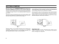
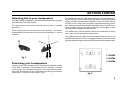
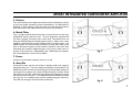
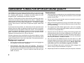
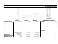
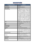
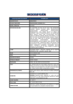
R
500 Series THX Select System Owners' Manual
INTRODUCTION & CONTENTS
Congratulations on your
purchase!
This 500 Series THX Select System is the result of an
extensive Research and Development program undertaken
to provide you with accurate, uncompromised
reproduction of movie soundtracks and music. With
attention to detail second to none, these loudspeakers not
only guarantee outstanding enjoyment but their elegant,
clean lines also allow them to integrate easily into the home.
Please read and retain this manual, it contains much useful
information that will ensure you get the best from your new
system.
2
Introduction & Contents.....................................2
Brief Introduction to Home THX .....................3
Getting Started ..................................................4
MS502 Subwoofer Amplifier...............................6
Subwoofer Tuning for
Optimum Sound Quality ....................................8
Taking Care of Your Loudspeakers .................9
Safety Precautions ............................................10
Specifications ....................................................11
A BRIEF INTRODUCTION TO HOME THX
Incorporating a series of patented electronic and
loudspeaker developments, home THX is the ultimate in
sound for multi-channel home cinema systems. The system
was developed after it was realised that conventional audio
components could not satisfactorily reproduce movie
soundtracks in the home environment.
As well as more accurately reproducing the highly complex
and competing sound fields present in multi channel
soundtracks, home THX successfully adjusts audible tonal
and spatial anomalies. These are caused by the reproduction
of movie soundtracks, that are really designed for playback
in cinemas, in the more compact home environment.
Manufactured under license from Lucasfilm
Ltd. Lucasfilm THX are registered
trademarks of Lucasfilm Ltd
THX Select was developed specifically for the smaller room,
calibrated to define reference level performance in
environments of about 2000 cu. ft.
THX Select gives you full confidence that each certified
component will perform as “the best in it’s class”.
3
GETTING STARTED
Connecting your MS500 THX Select System
Please do not compromise the performance of your system by using inferior quality cables. Mordaunt-Short recommends that high quality cables
of 16 gauge or higher be used. Your professional dealer will give you
good advice.
There are two pairs of terminals on the rear of every speaker which
permit bi-wiring if desired. For standard (non bi-wire) cable connection,
leave links in place and use either pair of terminals (fig. 1).
If your speakers are wired incorrectly they will be out of phase and sound
hollow and indistinct, with a weak bass. Re-check your connections for
correct polarity and reverse the connections if necessary
Bi-wiring sends the bass and treble frequencies down separate speaker
cables, resulting in a clearer, more focused sound. To bi-wire each speaker
loosen the upper pair of terminals and allow the binding post links to
disconnect (fig. 2). Use two runs of cable, or specific bi-wire cable,
between the amplifier and each pair of terminals
fig. 2
fig. 1
Observing polarity is of the utmost importance while connecting your
loudspeakers. Ensure that the red (+) terminals on your amplification
system are connected to the red (+) on the speaker, and black (-) on
your amplification system to black (-) on your speakers.
4
Important note
Always unplug all A.C. powered components before making any loudspeaker or component connections. This will avoid the risk of electric
shock or damage to your equipment.
GETTING STARTED
Attaching feet to your loudspeakers
Our floorstanding loudspeakers come with feet and spikes that will greatly
improve stability and sound quality.
The spikes attach to the bottom of the feet with the aid of a threaded
guide (fig. 3)
There are eight pilot holes on the bottom of the speakers. The feet are
located and secured here with the wood screws supplied (fig. 4). Level as
required.
Your MS502 front left and right speakers should be placed equidistant to
the left and right of your screen far enough apart to ensure good stereo
imaging, and with the subwoofers facing out. If they are too far apart or
too close to the corners of the room they will sound distracting and distant. Although normally best suited facing straight ahead it may be necessary (if positioned close to side walls) to ‘toe-in’ the units slightly to avoid
less than perfect imaging and treble response.
Your MS504 centre channel speaker needs to be placed above or below
your screen, directly facing the listening position.
Your MS506 dipole surrounds should be situated relatively high on the
sidewalls at the rear of the room. It is suggested that they are wall mounted
using the supplied fixings or alternatively placed on suitable speaker stands.
fig. 3
1. MS502
2. MS504
3. MS506
fig. 4
Positioning your Loudspeakers
Properly placed, your Mordaunt-Short THX Select loudspeaker system
will provide an excellent, wholly satisfying sound. However, with each
room varying in size, dimension and layout, it will be necessary to experiment with the placement of your loudspeakers in order to gain optimum
performance. A typical set-up is shown in fig. 5.
fig. 5
5
MS502 INTEGRATED SUBWOOFER AMPLIFIER
Each of your MS502’s have a built in dedicated subwoofer amplifier specially designed to deliver powerful low frequencies to the sub-woofer
drive unit mounted on the side of each MS502. This integrated system
gives the best possible bass reproduction with the minimum of adjustments and makes a separate subwoofer unnecessary. The controls are
explained here.
1.
2.
3.
5.
4.
6.
8.
7.
1. EXT/THX Input
This is a line level input for connection to the subwoofer line level output
of a Dolby Digital/DTS/THX or other surround-sound processor.
2. Loop Output
The signal applied to the EXT/THX input socket is ‘looped’ back out
through this socket so that it can be connected to another subwoofer unit
in a daisy chain.
3. THX / EXT / INT Input Switch
This switch selects which mode the MS502 operates in.
• THX mode selects the EXT/THX input socket and disables the
internal volume control and internal crossover circuits, as required by
Lucasfilm THX when used with THX certified electronics (wiring
configuration shown in fig. 7 opposite).
• EXT mode also selects the EXT/THX input socket but enables the
volume control and internal crossover circuits for use with a non THX
certified surround-sound processor (wiring configuration shown in fig.
7 below). Volume control should be adjusted for best sound balance.
• INT does not require a separate line level connection to the MS502.
In this mode the user can connect the MS502 as a conventional speaker
by using a set of normal speaker leads. The subwoofer derives its input
signal internally and thus does not need a separate input. This mode
is used with either a stereo or Pro-Logic receiver (wiring configuration
shown in fig. 8 below). The volume control should initially be set to
‘INT REF’ position, and then adjusted by ear for best sound balance.
4. Phase
fig. 6
6
Selects subwoofer output to be either in or out of phase (180 degrees).
This allows you to match the phase of your MS502s to different listening
positions and that of other speaker systems used at the same time.
MS502 INTEGRATED SUBWOOFER AMPLIFIER
5. Volume
This control allows you to adjust the volume of the low frequency output
of your sub woofer amplifier for best sound-balance. This adjustment is
defeated in THX mode as THX approved surround-sound processors
allow subwoofer level adjustments to be done by the processor.
6. Notch Filter
This is a single band Parametric EQ that is a powerful tool to help your
loudspeaker system sound it’s best. The low frequency response that
you hear is actually a function of the room itself. The Notch Filter can
help your MS502s adapt to the listening environment. Often, the in-room
response is dominated by a single resonant peak in the bass region. The
MS502 system can overcome this problem by tuning the in-built notch
filter to the same frequency as the problem resonance. The notch then
attenuates this frequency only and gives a more even, flatter bass response. Two levels of cut –6dB (shallow) and –12dB (deep) are available.
See “EQ Adjustment” section for full details.
fig. 7
7. Power
Switches the subwoofer amplifier power on or off.
8. Auto/On
If switched to auto, the amp will remain in standby mode until a signal is
detected at the input. The unit will then automatically switch itself on. The
MS502 subwoofer will then automatically go back into standby mode if an
input signal is not present at the input for approximately 5 minutes. When
the switch is in the ‘ON’ position the unit remains permanently on as long
as the main power switch is on. The LED positioned here indicates whether
the unit is on or in standby mode (red for standby and green when on).
This LED will also light red when a fault is detected.
fig. 8
7
SUBWOOFER TUNING FOR OPTIMUM SOUND QUALITY
Your MS500 system incorporates subwoofers built into the left and right
front speakers to generate substantial amounts of low-frequency energy
for a satisfying bass response. In addition the M500 system has been
designed to give a substantially flat frequency response.
However, the dimensions of some rooms and the positioning and nature
of furniture can cause the bass response to be uneven. Typically rooms
with this problem exhibit a ‘room mode’ where the room dimensions cause
reinforcement of a narrow band of frequencies. This leads to a slightly
‘boomy’ sound where a small band of frequencies appear louder than
normal.
If you experience this problem, we advise that you first experiment with
speaker placement. Begin by adjusting the distance between the speakers
and the distance from the speakers to the back wall etc. until a satisfactory
response is obtained. Remember to always use your ears as the ultimate
guide. Remember what sounds right to you, IS the optimum solution
regardless of measurements etc. that you may take.
If speaker placement alone is insufficient to solve these problems we have
incorporated a sophisticated notch filter that allows you to attenuate a small
range of frequencies for a more even, flatter bass. See instructions below:
Equipment required
•
EQ Test CD (supplied) containing eight test tones that will highlight any
low frequency ‘room mode’ resonances.
•
Sound Pressure Level (SPL) meter (not supplied): This gives an
accurate measure of the volume level of the tones emitted from the test
CD. SPL meters are available from Radio Shack (US), Maplin (UK) and
all good electrical shops. If you are unable to locate one ask your
dealer for advice.
8
Instructions
1.
Start by placing your loudspeakers in their intended locations (positioning
is discussed on page 5), ensuring that the notch filter is set to the OFF
position on both units.
2.
Set the levels of the whole speaker system as required for optimum
response (fixed in THX mode).
3.
Sitting in the listening position (as per fig.5) set the SPL meter range to
75 dB, it’s weighting to C, and set the response to slow if it has a slow/
fast response setting.
4.
The supplied test CD includes eight tracks, each one a specially
recorded tone at 1/6 octave spacing (in addition, each tone corresponds
to a value on the supplied table).
5.
Play each track on the CD in turn. Sitting in the listening position and
using the table provided, record the reading shown on your SPL meter
for each track played on the table provided. Should any one frequency
be 6dB-12dB above the average of the others, then use of the Notch
filter may be beneficial. Proceed as follows.
6.
Go to the rear of each MS502 and switch the notch filter to its –6dB
setting and adjust the notch filter frequency knob to the approximate
frequency of the highest reading taken as above. Always adjust both
notch filters (one for each speaker) together in tandem.
7.
Play the test CD again and record a second set of SPL readings in the
table to verify the improved flatness of response.
8.
Repeat steps 5 and 6 until a satisfactory fairly flat response is obtained.
TAKING CARE OF YOUR LOUDSPEAKERS
9.
Should more than 6dB of cut be required (i.e. one measurement is more
than 12dB above the average of the others) the notch filter can be set
to the –12dB setting and the process repeated.
Driver Precautions
By far the most common cause of loudspeaker failure, and one that is
understandably not covered by guarantee, is damage to the voice coils
caused by amplifier overload. This is generally due to the common belief
that if a speaker is rated at more than the amplifier’s output rating, there is
no chance of blowing that speaker.............
This is not the case!
A relatively small amplifier (i.e. 20 watts) can damage speakers like these
by “clipping” the signal, a symptom identified by lack of detail in music
and distortion. If this occurs TURN IT DOWN! If you don’t want to
blow up your speakers but want louder sound, please purchase a more
powerful amplifier.
Grilles
Mordaunt-Short loudspeakers have been designed for optimum listening
with grilles in place. The best overall performance will be had with the
tweeter protection grilles removed (if fitted, they are held in place
magnetically) and with the main grilles in place. Take care when removing
the tweeter grilles as the tweeter domes are very sensitive.
Cabinet Care
Cabinets should be dusted and lightly polished as required. Do not use
solvent based cleaners as they may damage the cabinet surface. Do not
expose the cabinets to strong, direct sunlight, high temperatures, high
humidity or allow them to become wet.
9
SAFETY PRECAUTIONS
Checking the Power Supply Setting
Plug Fitting Instructions (UK only)
For your own safety please read the following instructions carefully before
attempting to connect your MS502 unit to the mains.
The cord supplied with this appliance is factory fitted with a 13A mains plug fitted
with a 3A fuse inside. If it is necessary to change the fuse, it is important that
a 3A one is used. If the plug needs to be changed because it is not suitable for
your socket, or becomes damaged, it should be cut off and an appropriate plug
fitted following the wiring instructions below. The plug must then be disposed
of safely, as insertion into a 13A socket is likely to cause an electrical hazard.
Should it be necessary to fit a 3-pin BS mains plug to the power cord the wires
should be fitted as shown in this diagram. The colours of the wires in the mains
lead of this appliance may not correspond with the coloured markings identifying
the terminals in your plug. Connect them as
follows:-
•
•
Check that your unit indicates the correct supply voltage.
If your mains supply voltage is different, consult your dealer.
This unit is designed to operate only on the supply voltage and type that is
indicated on the unit. Connecting to other power sources may damage the unit.
Safety Precautions
This equipment must be switched off when not in use and must not be used
unless correctly earthed. To reduce the risk of electric shock, do not remove
the unit’s cover. There are no user serviceable parts inside. Refer servicing to
qualified service personnel. If the power cord is fitted with a moulded mains
plug the unit must not be used if the plastic fuse carrier is not in place. Should
you lose the fuse carrier the correct part must be reordered from your
Mordaunt-Short dealer.
The lightning flash with the arrowhead symbol within an equilateral triangle
is intended to alert the user to the presence of uninsulated ‘dangerous
voltage’ within the product’s enclosure that may be of sufficient
magnitude to constitute a risk of electric shock to persons.
The exclamation point within an equilateral triangle is intended to alert
the user to the presence of important operating and maintenance
instructions in the service literature relevant to this appliance.
This product complies with European Low Voltage
(73/23/EEC) and Electromagnetic Compatibility
(89/336/EEC) Directives when used according to this instruction
manual.
This product complies to the requirement UL 1270
and is approved by CSA-International for sale in the US
10
•
•
•
The wire which is coloured BLUE
must be connected to the terminal
which is marked with the letter ‘N’ or
coloured BLACK.
The wire which is coloured BROWN
must be connected to the terminal which
is marked with the letter ‘L’ or coloured
RED
GREEN /
YELLOW
E
FUSE
BLUE
N
L
BROWN
CORD
GRIP
The wire which is coloured GREEN/
YELLOW must be connected to the terminal which is marked with the letter
‘E’ or coloured GREEN.
Note
If your model does not have an earth wire, then disregard the Earth instruction.
If a 13 Amp (BS 1363) plug is used, a 3 Amp fuse must be fitted, or if any other
type of plug is used a 3 Amp or 5 Amp fuse must be fitted, either in the plug
or adaptor, or on the distribution board.
SPECIFICATIONS
MS502
Frequency Response
Sensitivity
Impedance (nominal)
Distortion
Power Rating
Drivers
MS504
MS506
MS502 Sub Amplifier
30Hz - 22kHz
80Hz - 22kHz
80Hz - 22kHz
90dB
90dB
87dB
4 Ohms
4 Ohms
8 Ohms
Less than 2% at 90dB
Less than 2% at 90dB
Less than 2% at 90dB
15W - 150W rms
15W - 150W rms
15W - 150W rms
(1) 10” Long throw active woofer
(2) 5.25” Aluminium alloy mid / bass
(2) 5.25” Aluminium alloy mid
(2) 5.25” Aluminium alloy mid
(1) 1” Aluminium tweeter
(2) 1” Aluminium tweeter
Bypassable 2nd order LF
2.5way 4th order mid
Attenuated dipole LF
2.5-way 4th order mid
2nd order DVP HF
2nd order mid HF
Bi-wirable, gold-plated 5-way
Bi-wirable, gold plated 5way
Bi-wirable, gold plated 5way
binding posts/switched LFE/low-level
binding posts
binding posts
950 x 180 x 350 (mm)
180 x 500 x 195 (mm)
362 x 327 x 185 (mm)
17.5 kg
7.2 kg
6.7 kg
Floorstanding
Above/below screen
Wall mounted / half space
(1) 1” Aluminium tweeter
Filter Network
2nd order DVP HF
Connections
Output power
THD
S/N ratio
Sensitivity
THX mode
External input
Internal input
Notch filter
150W rms
<0.05%
>95dB ‘A’ weighted
100mV for 88dB SPL (THX standard)
250mV (for max ouput, vol control centred)
Gain of 1 (vol control centred)
-6dB/-12dB cut
15 to 100Hz range
Maximum Power
consumption
350W
and hi-level active LF inputs
Size (HxWxD)
Weight (each speaker)
Operating Position
11