1
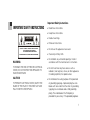
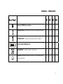
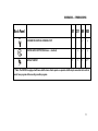
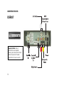
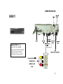
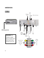
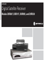
USER GUIDE
Digital Satellite Receiver
Models DSR207, DSR317, DSR505, and DSR530
CONTENTS
IMPORTANT SAFETY INSTRUCTIONS ..........................................................................................1
DSR BASICS — SYMBOLS/ICONS ...............................................................................................6
Front Panel ............................................................................................................................6
Back Panel ............................................................................................................................7
CONNECTING YOUR DSR ..........................................................................................................10
i
Important Safety Instructions
IMPORTANT SAFETY INSTRUCTIONS
• Read these instructions.
• Keep these instructions.
CAUTION
RISK OF ELECTRIC SHOCK
CAUTION: TO REDUCE THE RISK OF ELECTRIC SHOCK,
DO NOT REMOVE COVER (OR BACK).
NO USER-SERVICEABLE PARTS INSIDE.
REFER SERVICING TO QUALIFIED SERVICE PERSONNEL.
• Heed all warnings.
• Follow all instructions.
• Do not use this apparatus near water.
• Clean only with dry cloth.
WARNING
• Do not block any ventilation openings. Install in
accordance with the manufacturer’s instructions.
TO REDUCE THE RISK OF FIRE OR ELECTRICAL
SHOCK, DO NOT EXPOSE THIS APPLIANCE TO
RAIN OR MOISTURE.
• Do not install near any heat sources such as
radiators, heat registers, stoves, or other apparatus
(including amplifiers) that produce heat.
CAUTION
• Do not defeat the safety purpose of the polarized
or grounding-type plug. A polarized plug has two
blades with one wider than the other. A groundingtype plug has two blades and a third grounding
prong. The wide blade or the third prong is
provided for your safety. If the provided plug does
TO PREVENT ELECTRICAL SHOCK, MATCH THE
BLADE OF THE PLUG TO THE WIDE SLOT AND
FULLY INSERT IN RECEPTACLE.
1
IMPORTANT SAFETY INSTRUCTIONS
not fit into your outlet, consult an electrician for
replacement of the obsolete outlet.
• Protect the power cord from being walked on or
pinched, particularly at plugs, convenience
receptacles, and the point where they exit from the
apparatus.
• Use only attachments and accessories specified by
the manufacturer.
• Unplug this apparatus during lightning storms or
when unused for long periods of time.
• Refer all servicing to qualified service personnel.
Servicing is required when the apparatus has been
damaged in any way, such as when the powersupply cord or plug is damaged, liquid has been
spilled or objects have fallen into the apparatus, the
apparatus has been exposed to rain or moisture,
does not operate normally, or has been dropped.
2
Repairs
If you find the unit in need of repair, contact Star
Choice for repair or replacement.
Damage Requiring Service. Unplug this equipment
from the power source, and contact a qualified
service provider if any of the following situations
occurs:
• If the power supply cord or plug is damaged.
• If liquid or objects have fallen into the unit.
• If the unit became wet from rain or water.
• If the unit was dropped or damaged.
• If the unit’s performance changes.
Service. Do not try to service this product yourself. If
you open or remove the cover, you may be exposed
to dangerous voltage or other hazards and may void
the unit’s warranty. Contact a qualified service
provider for all service.
IMPORTANT SAFETY INSTRUCTIONS
Replacement Parts. If replacement parts are
required, be sure the service technician uses
replacement parts specified by the manufacturer or
have the same characteristics as the original part.
Unauthorized substitution may result in risk of fire,
electric shock, or other hazards.
Safety Check. After the unit is serviced or repaired,
ask the service technician to perform safety checks
to find out if the unit is in proper operating condition.
Regulatory Information
Federal Communications Commission Radio and
Television Interface Statement for a Class ‘B’ Device
This device complies with part 15 of the FCC Rules.
Operation is subject to the following two conditions:
(1) This device may not cause harmful interference,
and (2) this device must accept any interference
received, including interference that may cause
undesired operation.
This equipment has been tested and found to comply
with the limits for a Class B digital device, pursuant to
part 15 of the FCC Rules. These limits are designed
to provide reasonable protection against harmful
interference in the residential installation. This
equipment generates, uses, and can radiate radio
frequency energy and, if not installed and used in
accordance with the instructions, may cause harmful
interference to radio communications. However,
there is no guarantee that interference will not occur
in a particular installation.
If the equipment does cause harmful interference to
radio or television reception, which can be
determined by turning the equipment off and on, the
user is encouraged to try to correct the interference
by one of the following measures:
•
Increase the separation between the equipment
and the affected receiver.
•
Connect the equipment into an outlet on a circuit
different from the one the receiver is on.
Consult the dealer or an experienced radio/TV
technician for help.
3
IMPORTANT SAFETY INSTRUCTIONS
Changes or modification not expressly approved by
the party responsible for compliance could void the
user’s authority to operate the equipment.
the equipment complies with the standards of 47
CFR, Paragraphs 15.107 to 15.109.
Declaration of Conformity
This Class B digital device complies with Canadian
ICES-003.
According to 47 CFR, Parts 2 and 15 for Class B
Personal Computers and Peripherals, and/or CPU
Boards and Power Supplies used with Class B
Personal Computers, Motorola, Inc., 101 Tournament
Drive, Horsham PA, 1-215-323-1000, declares under
sole responsibility that the product complies with 47
CFR Parts 2 and 15 of the FCC Rules as a Class B
digital device. Each product marketed is identical to
the representative unit tested and found to be
compliant with the standards. Records maintained
continue to reflect the equipment being produced and
can be expected to be within the variation accepted,
due to quantity production and testing on a statistical
basis as required by 47 CFR 2.909. Operation is
subject to the following condition: This device must
accept any interference received, including
interference that may cause undesired operation. The
above-named party is responsible for ensuring that
4
Canadian Compliance
IMPORTANT SAFETY INSTRUCTIONS
© 2007 Motorola, Inc. All rights reserved. No part of this
publication may be reproduced in any form or by any means
or used to make any derivative work (such as translation,
transformation, or adaptation) without written permission
from Motorola, Inc.
MOTOROLA and the Stylized M logo are registered in the
US Patent and Trademark Office. All other product or service
names are the property of their respective owners.
Motorola reserves the right to revise this publication
and to make changes in content from time to time
without obligation on the part of Motorola to provide
notification of such revision or change. Motorola
provides this guide without warranty of any kind,
implied or expressed, including, but not limited to, the
implied warranties of merchantability and fitness for a
particular purpose. Motorola may make
improvements or changes in the product(s) described
in this manual at any time
.
5
DSR BASICS — SYMBOLS/ICONS
Front Panel
207 317 505 530
ON/STANDBY.
6
√
√
√
√
GO BACK To return to a previous menu or the last channel viewed.
√
√
√
OPTIONS To display the Main Menu.
√
√
√
NAVIGATION To navigate within menus or change channels up and
down.
√
√
√
SELECT To select a highlighted menu option.
√
√
√
DSR BASICS — SYMBOLS/ICONS
Back Panel
207 317 505 530
Back panel POWER cord connection.
√
TELEPHONE LINE For Instant Pay-Per-View (IPPV) reportback and caller
ID.
ANTENNA INPUT For analog off-air broadcast antenna or Cable TV.
√
√
√
√
√
√
√
√
√
√
√
DIGITAL VIDEO INTERFACE (DVI).
CH3/4 SWITCH To set the RF output to channel 3 or 4.
√
√
√
√
RF OUTPUT Modulated Channel 3/4 Output or Off-air Broadcast/Cable
Pass-through Output
√
√
√
√
7
DSR BASICS — SYMBOLS/ICONS
Back Panel
Y Pb Pr
207 317 505 530
USB PORTS (for future use)
1
1
1
2
COMPOSITE VIDEO OUTPUTS
1
2
2
2
√
√
2
2
2
OPTICAL DIGITAL AUDIO OUTPUT
√
√
√
S-VIDEO OUTPUT
√
√
√
COMPONENT VIDEO OUTPUT
STEREO AUDIO OUTPUTS
8
1
DSR BASICS — SYMBOLS/ICONS
Back Panel
UHF
207 317 505 530
UHF REMOTE CONTROL ANTENNA PORT
DIGITAL AUDIO OUTPUT (RCA/coax — electrical)
SATELLITE INPUT
1
√
√
√
√
√
1
1
2**
**Note: The DSR530 is equipped with two satellite tuners. Each requires a separate satellite input connection to be able to
watch one program while recording another program.
9
CONNECTING YOUR DSR
Make sure that the satellite receiver is not plugged into a power source before you connect any cables
to the receiver. First connect the satellite input from your satellite dish to your receiver.
There are several options to connect your DSR, and not every DSR model, TV, or other component
includes all of the connection types described below. Review the appropriate manuals if necessary to
determine the best connection for your system.
Video: Use Composite video output (better), S-Video output (best for standard definition), Component
video, or DVI outputs (best for high definition) to connect the DSR directly to your television, VCR, and
home theater A/V receiver.
Channel 3/4 RF modulator output to TV: If your TV is equipped with only one signal input connection
(usually labeled Antenna/CATV input), connect the DSR’s modulated RF output to TV input to receive
picture and sound with your TV tuned to either channel 3 or 4, depending on the channel 3/4 slide
switch setting on the back of your DSR.
Audio: The modulated RF output also provides audio along with video to televisions or VCRs (good).
Utilize the stereo audio output (better) or the coaxial or optical Digital audio outputs (best) to connect
the DSR directly to your television, VCR, and home theater A/V receiver.
10
CONNECTING YOUR DSR
Modem: Connect the telephone jack to a home telephone jack for Instant Pay-Per-View (IPPV)
reportback and Caller ID. Star Choice will not permit IPPV unless this remains connected.
Ant In: If applicable, connect the external antenna input for local off-air or cable TV broadcast. The DSR
will pass-through this RF source to the RF Output Connection when the DSR is in standby mode.
Once the above connections are secure, plug the DSR power cord or separate power supply (in the
case of the DSR207) into a standard power outlet. Wait one minute, and then press the ON button
located on the satellite receiver’s front panel.
Notes:
Video and audio quality should be best when you connect the DSR directly to your TV/monitor/projector
and an optional audio system. Use quality cables designed for these applications. Home theater A/V
receivers can provide a method to connect multiple input sources if your TV does not have enough
input connectors, and some home theater A/V receivers may enhance the video resolution or quality.
Refer to your home theater A/V receiver instructions for further information.
If you are using the component or DVI video outputs, you may have to toggle the HDTV mode select
button behind the flip-down door on the front panel of a DSR5xx series product. This toggles the HDTV
output between 1080i, 720p, 480p, 480i, and native modes. Native mode (0000) is the original
transmitted signal from the network/broadcaster. You should leave this on native mode unless your TV
or monitor requires a specific mode, such as 1080i.
11
CONNECTING YOUR DSR
DSR207
Important Note: Not all
connections are required.
Review your television or home
theatre manual for the best
connections for your system.
12
CONNECTING YOUR DSR
DSR317
Important Note: Not all
connections are required.
Review your television or home
theatre manual for the best
connections for your system.
13
CONNECTING YOUR DSR
DSR505
Off-Air Antenna
or Cable TV
MPEG4 Expansion Slot
Power
Important Note: Not all
connections are required.
Review your television or home
theatre manual for the best
connections for your system.
14
DVI or
DVI to HDMI
Connection to
HDTV
Telephone
Line
Coaxial
Cable to
TV
Optical
Audio
UHF Remote Control Antenna
Digital
Audio
S-Video
USB
(Reserved for
Future Use)
Satellite
In
Composite Video (Yellow)
Component
VideoTo HDTV
Left Audio (White)
(Green)
Right Audio (Red)
(Blue)
(2 Sets)
(Red)
CONNECTING YOUR DSR
DSR530
MPEG4 Expansion Slot
Important Note: Not all
connections are required.
Review your television or home
theatre manual for the best
connections for your system.
15
Motorola, Inc.
101 Tournament Drive
Horsham, PA 19044 U.S.A.
Star Choice Communications Inc.
2924 – 11 Street NE
Calgary, AB T2E 7L7
http://www.motorola.com
http://www.starchoice.com
534019-001-d
12/07