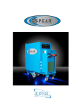
Download Moorwood Vulcan MLE30F-F-C Owner`s manual
Transcript
SNORKEL
CONVECTION OVEN
OWNER’S MANUAL
Click here for
Parts List
County of Destination
GB and IE
Manual Part No: 930087-01
Manual Rev No: 1
SNORKEL Gas Convection Oven
-1–
Manual Part No: 930087-01
Manual Rev No: 1
SNORKEL Gas Convection Oven
-2–
IMPORTANT CUSTOMER INFORMATION
Please check the gas tap and thermostat will press and release
freely prior to lighting the burner as this is part of the unit’s
safety mechanism.
It is particularly important to check this following spillage as
solidified fats and carbonised meat juices can impair the
valves correct operation.
IMPORTANT INFORMATION INSTALLATION ENGINEER
Please ensure the customer is made fully aware of how the
gas tap and thermostat operate and the importance of
checking its operation daily.
Manual Part No: 930087-01
Manual Rev No: 1
SNORKEL Gas Convection Oven
-3–
Model No.
Product Description
Snorkel-2
Snorkel Convection Oven
Manual Part No: 930087-01
Manual Rev No: 1
Flexible
Rev.
Date
Hose Size
1
08/03/00
¾” BSP hose
SNORKEL Gas Convection Oven
-4–
INDEX
Page
Cover:
1
Important Information Sheet:
2
Revision:
3
Index:
4
Introduction:
4&5
General Introduction
4
Important Note
5
Specification:
6-8
Gas & Electric Dimensions/Connection
6
Line Drawing
7
Wiring Diagram
8
Installation:
9 - 11
Important Note/Positioning
9
Positioning/Connection
10
Checking & Commissioning
11
Users Instruction:
12- 23
Important Note
12
Operation
13 - 18
Cooking Guide
18 - 22
Cleaning
22 & 23
Service/Maintenance:
24 - 35
Routine Maintenance
24
Fault Finding
25
Instructions
25 - 35
Spare Parts:
36 – 46
Fabricated Panels
36 - 38
Cladding & Finish Panels
39-& 41
Oven Furniture
42
Gassing Assembly
43 & 44
Electric Assembly
45 & 46
Warranty Cover Sheet:
Manual Part No: 930087-01
Manual Rev No: 1
47
SNORKEL Gas Convection Oven
-5–
INTRODUCTION
This manual contains all the required information to ensure that your new appliance is installed correctly
and that you have all the information necessary to identify and order spare parts. It also contains
comprehensive instructions for the user and for cleaning the appliance.
To maintain peak performance, it is recommended that the appliance be regularly serviced and that
when ordering spare parts, reference be made to the appropriate list quoting the Part No. and the
description therein. THE FITTING OF A NON-STANDARD PART MAY VOID ANY GUARANTEE.
All work carried out on this appliance during installation or servicing, must be performed by a
competent person and the connection of the appliance to the gas supply MUST be carried out by
qualified personnel in accordance, where applicable, with the relevant regulations.
The siting of the appliance and the connection to the gas/electrical supply must comply with the latest
GAS SAFETY (INSTALLATION & USE) REGULATIONS 2000: the requirements of the FIRE PRECAUTIONS
ACT 1971; the HEALTH & SAFETY AT WORK, ETC ACT 1974, the BUILDING STANDARDS (SCOTLAND)
CONSOLIDATION REGULATIONS 1971. Detailed recommendations are contained in British Standards
BS5440: Part 1:2000, BS5440: Part 2:2000, BS5588: Part 0:1996, BS5588: Part 11:1997 & BS6173: 2001.
The installation must comply with the requirements of Local Authority Regulations and the wiring must
comply with the latest I.E.E. Regulations.
An easily accessible stopcock must be fitted in the gas supply adjacent to the appliance for use in
emergency. In addition a fused mains isolator must be fitted in the electricity supply.
The details of the gas supply will be found on the Data Plate, which is located on the rear of the flue
upstand/splashback panel.
WARNING: THIS APPLIANCE MUST BE ELECTRICALLY EARTHED
Improvements
The policy of Viscount Catering Ltd is such that, each product is subject to continual development and
may, therefore, be subsequently improved. The company reserves the right to alter the design of any
appliance without prior notification and without the responsibility to update any delivered or in-service
appliance and furthermore, without incurring the responsibility for altering these instructions. In such
circumstances, it may be found that the appliance detailed herein differs in certain respects from the one
supplied.
IT IS IMPORTANT, THEREFORE, TO QUOTE THE SERIAL No. AND THE APPLIANCE MODEL No. IN ALL
COMMUNICATIONS WITH THE COMPANY
Manual Part No: 930087-01
Manual Rev No: 1
SNORKEL Gas Convection Oven
-6–
Introduction (cont.)
Important
Before installing any item please refer to the installation instructions.
We recommend that our authorised service agents carry out all servicing other than routine cleaning and
will accept no responsibility for work carried out by other persons.
For satisfactory operation, parts of catering equipment become hot. Suitable precautions must be taken
to avoid accidental burns therefore the appliance should be positioned to minimise the possibility of
accidental touching. It is the supervisors’ responsibility to warn users to wear suitable protection and to
follow correct operation and cleaning procedures.
For the details of your nearest Service Agent for all warranty and repair work, you should contact: The Service Manager,
Viscount Catering Limited
Provincial Park
Nether Lane
Ecclesfield
Sheffield
S35 9ZX
Tel: +44 (0)114 2574500
Fax:+44 (0)114 2574527
Spares can be obtained via the Spare Parts Department at the above address.
IT IS IMPORTANT, TO QUOTE THE SERIAL No. AND THE APPLIANCE MODEL No. IN ALL
COMMUNICATIONS WITH THE COMPANY.
Manual Part No: 930087-01
Manual Rev No: 1
SNORKEL Gas Convection Oven
-7–
SPECIFICATION
Snorkel Convection Oven
Gas Pressure
Supply Pressure
Adjusted Pressure
Natural Gas
20 mbar
(8.0” wg.)
11.25 mbar
(4.5” wg.)
Propane Gas
37 mbar
(14.8” wg.)
37 mbar
(14.0” wg.)
Electrical Supply
240V, 50Hz, Single Phase
Gas Connection
½” BSP Taper Male (Rp ½ “)
When connecting using a flexible hose fit a ¾” BSP hose
Heat Input (Nett)
Natural Gas
m3/h
Burner x 2
Total
2.082
Injectors
Propane gas
Btu/h
kW
33,557
9.835
67,114
19.67
Kg/h
1.688
2.87 mm
Btu/h
kW
36,781
10.78
73,562
21.56
1.70 mm
Dimensions
Overall
900mm wide x 1010mm deep x 1600mm high
Oven Internal
735mm wide x 675mm deep x 510mm high
Oven Shelf
720mm wide x 530mm deep
Cooking Volume
0.22m3 (7.7 ft.3)
Weight
300kg
Thermostat Calibration
As Thermostat knob in °C
Manual Part No: 930087-01
Manual Rev No: 1
SNORKEL Gas Convection Oven
-8–
Specification (cont.)
Manual Part No: 930087-01
Manual Rev No: 1
SNORKEL Gas Convection Oven
-9–
Specification (cont.)
Wiring Diagram
Manual Part No: 930087-01
Manual Rev No: 1
SNORKEL Gas Convection Oven
- 10 –
INSTALLATION
Important
Your attention is drawn to the latest, GAS SAFETY (INSTALLATION & USE) REGULATIONS 2000.
This appliance MUST be installed by a competent person in accordance with these and any other relevant
regulations. Users, too, should be aware of the regulations governing the use of gas appliances,
particularly with respect to the need for regular servicing.
The installation wiring of this appliance MUST comply with the latest I.E.E. Regulations.
WARNING: THIS APPLIANCE MUST BE ELECTRICALLY EARTHED
Before Installation
Before commencing installation, remove all packaging materials from the appliance. It is suggested that
any protective film adhering to the stainless steel panels should be left on until installation is completed.
BUT THIS MUST BE REMOVED BEFORE COMMISSIONING OR OPERATING THE APPLIANCE.
Check the appliance Data Plate (secured to the top plate of the control panel), to ensure that the
appliance is suitable for the gas supply available.
Ensure that the floor upon which the appliance is to stand is level and capable of adequately supporting
the weight of the appliance. TO COMPENSATE FOR SOME UNEVENNESS OF THE FLOOR, THE
APPLIANCE FEET ARE ADJUSTABLE.
THE FLOOR MUST BE FIREPROOF. If it is not, or if any adjacent wall or surface s made of a combustible
material, then the installer must ensure that the requirements of the LOCAL FIRE REGULATIONS are
observed.
Positioning
Place the appliance in position allowing a minimum gap of 75mm (3”) at the rear and at least 150mm (6”)
between the sides of the appliance and any adjacent walls. The minimum distance between the top of
the appliance and any overshelf or ceiling construction of a combustible material must be 420mm
(16½“).
Adequate ventilation is essential for safe operation of a gas appliance. A supply of fresh air is necessary
for the correct combustion of the gas and there must be a means of exhausting the heat and the
products of combustion from the kitchen. It is recommended that the appliance be sited below a
ventilating hood, one preferably connected to an extractor system incorporating a grease filter.
Manual Part No: 930087-01
Manual Rev No: 1
SNORKEL Gas Convection Oven
- 11 –
Installation (cont.)
Important Note
The appliance MUST NOT be connect DIRECTLY to a flue or ventilating system, although the flue
products of two or more appliances may be directed into a common outlet when building a suite of
appliances (see separate instructions for suiting appliances).
Ensure that the appliance is level in two places – front to rear and side to side. To check the level, it is
recommended that a spirit level be placed on a shelf in the open oven – NOT on top of the cooker! Level
can be achieved by adjusting any or all of the screw in feet in each corner of the base. Turn anticlockwise to lower and clockwise to raise the corner.
Gas Connection
Natural Gas: The size of the supply pipe should be no smaller than ½ “ BSP and an easily accessible stopcock must be
fitted in the gas line adjacent to the appliance. Although a rigid gas pipe is recommended, armoured
flexible pipe of a GAS COUNCIL APPROVED PATTERN must be used.
NOTE:
Due to the pressure loss through the snap connection fitting on flexi hoses you must fit a ¾”
flexible Hose
Ensure that all the pipes to the appliance are clean and free from swarf etc, BEFORE making the final
connection.
Propane Gas: Follow the same procedure as that for Natural Gas EXCEPT that the Gas Governor (incorporating within
the Double Solenoid Valve) IS DISABLED AT THE FACTORY by being screwed “fully” clockwise, - the Gas
Supply Tank or Cylinders are already fitted with a Gas Regulator.
Leak Test
Clean of any protective film from the stainless steel panels.
AT THIS STAGE, LEAK TEST THE WHOLE SYSTEM. THE GAS SAFETY REGULATIONS require that ALL
connections in the gas supply line between the Gas Meter and the appliance is tested for gas leaks.
THIS MUST BE DONE BEFORE COMMENCING TO COMMISSION THE APPLIANCE.
Manual Part No: 930087-01
Manual Rev No: 1
SNORKEL Gas Convection Oven
- 12 –
Installation (cont.)
Checking and Commissioning
ALTHOUGH EVERY APPLIANCE IS TESTED AND SET BEFORE IT LEAVES THE FACTORY, IT IS
IMPORTANT THAT THE INSTALLER RE-CHECKS CERTAIN FUNCTIONS BEFORE LEAVING THE SITE.
CHECK THE GAS PRESSURE AT THE APPLIANCE THUS: The pressure test point is located on the manifold pipe behind the removable lower fascia panel, which
is secured by two M5 screws.
Connect a manometer (U tube) to the test point. Turn on the gas supply and light and light the oven.
Check that the pressure reading agrees with the stated on the Data Plate.
Go through the lighting procedure, as listed in the USER INTRUCTIONS, ensuring that all the neon lights
work and leave the oven set to 175°C for 20 minutes to ensure that it heats up and that the burner (and
red light) goes out when the temperature is reached.
SHOULD ADJUSTMENT BE NECESSARY, PROCEED AS FOLLOWS: FOR PROPANE GAS, the appliance governor (fitted to the solenoid valve) is disabled at the factory,
therefore any gas pressure problems should be REFERRED TO YOUR GAS SUPPLIER.
On the gas governor: - (part of the solenoid valve).
Remove the cap in order to gain access to the pressure adjusting screw.
Turn the pressure adjusting screw clockwise to increase the pressure or anti-clockwise to decrease it.
When the pressure reading is correct, refit the cap to the governor.
Turn the gas supply to the unit OFF at the stopcock and disconnect the manometer (U tube). Ensure that
the pressure test point screw is refitted.
Turn the gas supply to the appliance on at the stopcock and leak test the pressure test point.
Burner Aeration
The aeration of the burners is fixed and does not need adjusting.
Manual Part No: 930087-01
Manual Rev No: 1
SNORKEL Gas Convection Oven
- 13 –
USERS INSTRUCTIONS
Important Note
The attention of the user is drawn to the requirements of the latest GAS SAFETY (INSTALLATION & USE)
REGULATIONS 2000. This appliance must be used in accordance with those, particularly so in respect
of the need for regular servicing.
See also the sections of this manual referring to Cleaning and General Maintenance.
Safety Note
This appliance is intended for professional use and shall only be used by qualified personnel.
Parts and surfaces of this appliance get hot in use. It is the responsibility of the kitchen supervisor to
inform and warn every user and kitchen worker of this and, furthermore, to ensure those users wear and
use protective clothing when operating the appliance.
Should any adjustment or attention be necessary, you are advised to contact your nearest CORGI
(Confederation for the Registration of Gas Installers) Service Engineer immediately. The need for regular
servicing is detailed in the latest GAS SAFETY (INSTALLATION & USE) REGULATIONS 2000.
IF YOU THINK THAT GAS IS ESCAPING, ACT IMMEDIATELY. SHUT OFF THE GAS SUPPLY AT THE
METER OR EMERGENCY CONTROL, CONTACT THE SUPPLIER OF YOUR GAS IMMEDIATELY.
MAKE SURE THAT ALL USERS OF THIS APPLIANCE KNOW WHERE THE GAS SUPPLY STOPCOCK IS
LOCATED FOR THE USE IN AN EMERGENCY.
Improvements
The policy of Viscount Catering Ltd is such that each product is subject to continual improvement. The
company reserves the right to alter the design of any appliance without prior notification and without the
responsibility to update any delivered or in-service appliance and, furthermore, without incurring the
responsibility for altering these instructions.
In such circumstances, it may be found that the appliance detailed herein differs in certain respect from
the one supplied.
For further details or enquires please contact:
Viscount Catering Ltd, Provincial Park, Nether Lane, Ecclesfield, Sheffield, S35 9ZX
Tel:+44 (0)114 2570100
Fax:+44 (0)114 2570251
Manual Part No: 930087-01
Manual Rev No: 1
SNORKEL Gas Convection Oven
- 14 –
Users Instructions (cont.)
Controls
Power/Ignition
Switch (A)
Ignition Indicator
Main ON/OFF switch, connects controls to electrical supply and initiates
ignition sequence.
Glows whenever ignition system is in operation.
Light (B)
Auxiliary Fan
Switch (C)
Timer (D)
Controls operation of fan when doors are open to permit rapid cooling of
oven.
Selects time intervals up to 60 minutes. A bell rings at the end of selected period.
Note: Timer has no control over burners.
Load Control (E)
Controls variation of gas-input between 0 and 100% of full input. See also “Load
Control Settings,” page 16.
Thermostat (F)
Controls temperature inside oven through a range of 93°C to 260°C (200°F to
500°F) by controlling both burners
Thermostat Indicator
Glows whenever thermostat is in operation.
Light (G)
Door Microswitch
Cuts off fan and main burners automatically when doors are opened. May be
overridden by means of auxiliary fan switch, see above.
Manual Part No: 930087-01
Manual Rev No: 1
SNORKEL Gas Convection Oven
- 15 –
User Instructions (cont.)
Lighting Instructions
1)
Ensure that the external electrical supply is turned ON, by checking that the indicator light on
2)
Turn ON the gas supply and press the power switch (A) to the ON position. This will initiate
the power switch (A) is glowing.
Ignition sequence.
3)
When ignition sequence is complete the Ignition Indicator Light will glow.
4)
To light main burners ensure that the load control is set to any position other than OFF and turn
thermostat knob (F) to required setting
Note: When first lighting the appliance after installation or after an extended shut-down
period, it may be necessary to repeat step 2 a few times before ignition is complete, due to the
presence of air in gas line.
Important
The burners depend upon the fan operating for them to work safely and efficiently. To ensure this
happens an air proving (or pressure switch) is fitted, which will not allow mains gas to the burners until
the fan is operating. This also means that if the doors are opened during the cooking cycle, the fan will
stop and the burners will be extinguished until the doors are closed. At this stage the ignition sequence
will restart and the cooking cycle will continue.
To Turn off
1)
2)
For short periods, turn the thermostat knob to the OFF position.
For longer periods, (or if the appliance is to be left UNATTENDED), turn the thermostat knob to
the OFF position, switch OFF the power switch and close external gas/electric supplies.
Principles of Operation
The Snorkel system of controlled convection cooking uses the “Thermaire” method of air circulation,
which, together with the load control, allows the user to adjust the oven to suit their own recipes and
obtain the desired product results.
Air Circulation - The Thermaire fan in the oven moves the air and combustion products at high velocity
over the heat exchanger tubes, through the perforated side liner plates and over the products.
No insulating layer of cool air remains around the products being cooked, as heat is immediately and
continually supplied to the surface of the product, with the result that the products cook as quickly as
their size and nature permit.
Manual Part No: 930087-01
Manual Rev No: 1
SNORKEL Gas Convection Oven
- 16 –
Users Instructions (cont.)
Principles of Operation (cont.)
Controls: -
The thermostat controls the air temperature within the oven, cutting off the burners at
the required setting. The load control determines the amount of heat input into the oven and time taken
by the air in the oven to return to the selected thermostat setting with a specific load. The following
example is given merely as a basic guide to using the load control and is not related to any specific
product: If four shelves of a product cook correctly in 15 minutes at 177°C (350°F) and a load control setting of 4,
one rack should also cook correctly in 15 minutes at 177°C. But, since the load is only ¼, not so much
heat input is needed. Using a load control setting of 2, the single rack load receives a proportionately
smaller amount of heat. The load will take the same time at the same temperature as the four-rack load
and will be cooked to the same extent.
Recipe Adjustment: -
The Snorkel requires no special recipes. Excellent results can be obtained from
any good commercial recipe, using reduced cooking times.
Temperature Adjustment: -
The Snorkel will cook or bake full or partial loads at standard
temperatures with the load control correctly set. As with any oven, the user may wish to raise or lower
the temperature by up to 14°C (25°F) to give the preferred product result.
Time Reduction: -
Owing to the many variations in recipes, ingredients and individual tastes, exact
times for different products cannot be given. The “Cooking Guide” page 18 should be used only as a
guide. Check products at half cooking time, when cooking for the first time. The products may be
cooked, or if not, additional time may be calculated and allowed.
Important: -
When established, times and load control settings should be noted on each recipe.
During baking, the design and correct operation of the oven are of great importance, but product quality
and satisfactory results also depend upon the recipe, ingredients used, and the accuracy and care with
which the ingredients are measured and the recipe instructions followed.
Forced convection cooking is faster than in a conventional oven, therefore over-cooking is more
common, take care not to cook products faster than is practical for the best results. Since forced
convection supplies heat to the surface of the product, the thicker and more massive a product,
according to type, the longer the time for it to absorb heat to cook.
Manual Part No: 930087-01
Manual Rev No: 1
SNORKEL Gas Convection Oven
- 17 –
User Instructions (cont.)
Capacity and Shelf Arrangements
The Snorkel oven has a maximum operating capacity of 7 shelves, which are supplied as standard. The
No. 8 position ensures maximum flexibility and correct shelf spacing.
The following arrangements are recommended, with the position numbers in sequence from the bottom
upwards: 1)
Seven (7) shelves in positions 1,2,3,4,6,7 & 8 for oven broiling, biscuits or reconstitution of
frozen packs at maximum capacity. Also recommended for general baking in sheet pans with
products not over 45mm (1 ¾”) high.
2)
Four (4) shelves in positions 1, 3, 5 & 7 for general baking in sheet pans, pie or cake tins and
pudding pans 76mm (3”) high, with products not over 89mm (3 ½”) high. Can also be used for
casseroles or meat dishes in “200 Series” food service pans 305 x 508 x 64mm (12” x 20” x 2
½”). (“Gastronorm” 324 x 527mm / 12 ¾” x 20 ¾” can also be accommodated).
3)
Three (3) shelves in positions 2, 4 & 7 for baking bread or cakes in loaf or tube pans and for high
meringue pies. Can also be used for casseroles, meat dishes or roasting in pans up to 100mm
(4”) deep, with products up to 115mm (4 ½”) high.
4)
Two (2) shelves in positions 1 & 5 for roasting turkeys and other roasts up to 178mm (7”) high.
Notes - a)
b)
With a shelf in No. 1 position, space below for a water pan is limited (See “Cooking
Guide” page 20)
When mixed loads or partial loads are cooked, other rack arrangements may be devised
to suit particular requirements.
Manual Part No: 930087-01
Manual Rev No: 1
SNORKEL Gas Convection Oven
- 18 –
User Instructions (cont.)
General Operating Information
Preheating
1)
2)
3)
Light the oven, see page 14.
Ensure that both doors are closed and set load control at HIGH.
Set thermostat to temperature required by recipe, or established by experience. Thermostat light
will glow until oven reaches set temperature (e.g. 10-15 minutes for settings between 149°C &
204°C 300°F & 400°F).
4)
Load the oven when thermostat light goes out for second time to indicate end of preheating
5)
Set load control to required setting.
cycle.
Loading
1)
Open doors (the fan and burners will automatically be cut-off) and load pans as quickly as
possible to conserve heat, centring them on shelves.
2)
Sheet or roast pans 457mm x 660mm (18” x 26”) should be pushed back to pan stops. Food
service and pudding pans, 305 x 580mm (12” x 20”) each, may be loaded two per shelf and
pushed back to pan stop.
3)
Take care to avoid spilling batter or liquids during loading.
4)
Close doors, cooking will begin. Set timer as required.
5)
After loading, set load control to suit product and load being cooked.
6)
When pre-set time is complete, timer will ring; check product for correct degree of cooking.
Unload, or set for additional time.
Unloading
1)
Ensure that adequate space is available for products to be unloaded from oven. Rapid unloading
conserves heat, essential if reloading for high volume production.
2)
Unloading is made easier if the shelves are pulled forward for better access to the pans or
3)
After unloading last batch of products, shut down the appliance.
alternatively use an unloading trolley/rack system.
Manual Part No: 930087-01
Manual Rev No: 1
SNORKEL Gas Convection Oven
- 19 –
User Instructions (cont.)
Load Control Settings
Dial Setting
% of Full Input
High
100
High
75
High
67
Medium
58
Medium
47
Medium
36
Low
23
Off
0
Common Convection Problems (Causes & Correction)
PROBLEM
CAUSE
REMEDY
Uneven browning, or
Load control set too high or
Reduce load control setting or
overcooking at edges of pans.
too many shelves used.
number of shelves.
Pulling to edge of pan or
Oven not level or sheet pans
Have oven levelled. Separate
spilling.
warped.
pans for baking batter
products from generalpurpose pans. If any pan shows
tendency to warp, remove it
from the baking group.
Overbrowning before cooked
Load control set too high.
Reduce load control setting.
Failure to maintain water in
Check water level frequently
oven or roasting temperature
and top-up or reduce roasting
too high.
temperature.
or shrinkage and overbrowning
at edges.
Excessive shrinkage.
Manual Part No: 930087-01
Manual Rev No: 1
SNORKEL Gas Convection Oven
- 20 –
User Instructions (cont.)
Cooking Guide
Appliance capacity and performance depends upon shelf arrangement and type of products being
cooked. To obtain best results, follow recommendations given on page 16.
The adjustable load control switch operates in conjunction with the thermostat to provide higher heat
input when required. For example, frozen foods require a very high heat input, particularly when oven is
fully loaded, and for this type of operation the load control should be set to HIGH. For conventional
cooking, intermediate load control settings may be used according to oven loading. The load control
does not affect oven temperature, which is controlled by the thermostat.
A pan of water (approx. 305 x 508 x 25mm/12” x 20” x 1”) may be placed in oven bottom to provide
humidity for reduction of shrinkage. Add water, if necessary, during roasting. Roasting pans should be
no deeper than necessary to hold drippings, usually 50 x 63mm (2” x 2 ½”).
Cooking time and shrinkage vary with roasting temperature, cut and grade of meat, and degree of
cooking required. Smaller cuts will generally show greater timesaving than larger cuts, at the same
temperature.
ROASTING
Product
Roast Standing Rib – Oven Ready
°C
°F
121
250
Time (Approximately
3 – 4 hours (Rare)
4 – 4 ½ hours (Medium)
Roast Rolled Rib – 9-10 kg (10-12 lbs.)
135
275
4 hours (Medium)
Roast Veal – 6.8 kg (15 lbs.)
149
300
3 hours (Medium-Well)
Turkeys – 6.8 kg (15 lbs.)
149
300
3 hours
Meat Loaf – 3.6-4.5 kg (8-10 lbs.)
177
350
45 – 60 minutes
Roast Lamb – 6.8 kg (15 lbs.)
149
300
3 hours (Medium-Well)
BAKING
Product
Time (Approximately
°C
°F
Scaled –2 - 2.7 kg (4.4 - 6 lbs.) per pan.
163-174
325-345
20 – 23 minutes
Scaled – 2.7 - 3.4 kg (6 – 7.5 lbs.)
157-168
315-335
22 – 25 minutes
Scaled –2.3 - 2.7 kg (5 - 6 lbs.) per pan.
149-163
300-325
25 – 35 minutes
CUP CAKES
177-204
350-400
6 – 12 minutes
CAKES
Sheet Cakes – 457mm x 660mm x 25mm
(18” x 26” x 1”)
ANGEL OR SPONGE CAKES
Sheet Cakes – 457mm x 660mm x 25mm
(18” x 26” x 1”)
Manual Part No: 930087-01
Manual Rev No: 1
SNORKEL Gas Convection Oven
- 21 –
User Instructions (cont.)
Cooking Guide (cont.)
Oven Broiling or Frying
Product
°C
°F
204-232
400-450
Time (Approximately
HAMBURGER PATTIES
Eight (8) - 0.5 kg (1 lb.)
4 – 5 minutes
Medium – Well Done
2 – 3 minutes
Six (6) - 0.5 kg (1 lb.) /
5 – 8 minutes
Four (4) - 0.5 kg (1 lb.)
7 – 10 minutes
FISH FINGERS – Frozen Breaded
28 g (1 oz)
177-204
350-400
6 – 10 minutes
71-85 g (2 ½-3 oz)
177-191
350-375
6 – 15 minutes
Fried – 0.9-1.1 kg (2–2 ½ lbs.) Bird
191-218
375-425
8 – 15 minutes
Fried – 1.1-1.4 kg (2 ½-3 lbs.) Bird
177-204
350-400
15 – 25 minutes
CHICKEN PIECES – Boiler or Oven
Re-heating prepared foods
Product
Frozen French Fries
°C
°F
204-232
400-450
Time (Approximately
6 – 8 minutes
Frozen Lunches (TV Dinners)
177-204
350-400
10 – 20 minutes
Frozen Entrees - 19mm x 25mm (3/4” x 1”)
149-177
300-350
10 – 20 minutes
Frozen Meals – 0.2 kg (8 oz) Foil packed
177-204
350-400
20 – 30 minutes
°C
°F
50 – 76mm (2 – 3”) deep
163-191
325-375
15 – 25 minutes
76 – 100mm (3 – 4”) deep
163-191
325-375
20 – 35 minute
177-204
350-400
5 – 6* minutes
Casseroles
Product
Time (Approximately
FOOD SERVICE PANS
FOIL PANS
Up to 38mm (1 ½”) deep
* Frozen 10 – 15 minutes
Manual Part No: 930087-01
Manual Rev No: 1
SNORKEL Gas Convection Oven
- 22 –
User Instructions (cont.)
Cooking Guide (cont.)
Miscellaneous Products
Product
Time Approximately
°C
°F
120 count per 23kg (50 lbs.)
204-232
400-450
20 – 25 minutes
100 count per 23kg (50 lbs.)
204-232
400-450
25 – 40 minutes
80 count per 23kg (50 lbs.)
204-218
400-425
30 – 50 minutes
Pizzas – Frozen or Pre-baked crust
218-246
425-475
5 – 10 minutes
Melted Cheese Sandwiches
204-218
400-425
8 – 10 minutes
Baked Potatoes
Special Procedures for Baking
YEAST BREAD begins to cook immediately in a convection oven and does not usually rise as much as in a
conventional oven. It is, therefore, necessary to allow a fuller proof, 2 ½ - 3 times increase in volume for
the best results.
PIES baked in the Snorkel oven should be placed 3 or 4 per 457 x 660mm (18 x 26”) sheet or bun pan to
assist the bottom crust to bake, facilitate handling and reduce the possibility of boiling over which spoils
the appearance of pies on lower shelves.
Note: PIES (Fruit/Custard). Pies in tins should be placed on 457 x 660 x 25mm (18 x 26 x 1”) pans for
baking.
Product
Time Approximately
°C
°F
Frozen Fruit Pies
177-191
350-375
30 – 45 minutes
Custard Pies
149-177
300-350
30 – 45 minutes
Meringue Pies
177-218
350-425
6 – 10 minutes
177-191
350-375
15 – 25 minutes
Scones
177-204
350-400
6 – 12 minutes
Drop Scones
177-204
350-400
6 – 15 minutes
Fruit Turnovers
457 x 660 x 25 (18 x 26 x 12) pans
Manual Part No: 930087-01
Manual Rev No: 1
SNORKEL Gas Convection Oven
- 23 –
User Instructions (cont.)
Cooking Guide (cont.)
Special Procedures for Baking
Product
Time Approximately
°C
°F
Rolls – 28g (1 oz)
177-204
350-400
5 – 10 minutes
Rolls – 43-71g (1 ½-2 ½ oz)
177-204
350-400
8 – 15 minutes
Loaf Bread – 0.5kg (1 lb.)
163-191
325-375
20 – 40 minutes
Sweet Rolls & Danish Pastries
163-191
325-375
5 – 15 minutes
Quick Breads/Biscuits – Rolled 13 mm (1/2”)
177-204
350-400
5 – 15 minutes
Muffins
163-191
325-375
6 – 18 minutes
Corn Muffins
168-196
335-385
10 – 20 minutes
Yeast Breads(must be fully proofed)
Cleaning the Equipment
It will be found that it takes less time and effort if appliances are cleaned every day, particularly while
they are still warm and before grease and spillage are burnt on. PROPRIETARY OVEN CLEANER MUST
BE USED WITH CARE. THEY ARE HIGHLY CORROSIVE AND MAY CAUSE DAMAGE TO SURFACES AND
COMPONENTS.
The oven shelves can be removed for cleaning. Withdraw the shelves in the normal way, rub them free of
grease using an absorbent pad and wash in a hot detergent solution. Rinse and dry before replacing
them.
The shelf supports are removed by lifting them free of the liner sides. They, too, can be washed in a hot
detergent solution and rinsed and dried before replacing.
Clean the oven interior and the oven door-lining daily, using a hot detergent solution. This is especially
necessary if a spill over has occurred, meat has been roasted or fruit pies baked. Rinse with clean water.
Stubborn accumulations can be gently scraped off after soaking.
DO NOT USE CAUSTIC OR ABRASIVE CLEANING AGENTS.
Manual Part No: 930087-01
Manual Rev No: 1
SNORKEL Gas Convection Oven
- 24 –
User Instructions (cont.)
Cleaning the Equipment (cont.)
It will be found that it takes less time and effort if appliances are cleaned every day, particularly while
they are still warm and before grease and spillage are burnt on.
PROPRIETARY OVEN CLEANER MUST BE USED WITH CARE. THEY ARE HIGHLY CORROSIVE AND MAY
CAUSE DAMAGE TO SURFACES AND COMPONENTS.
The oven shelves can be removed for cleaning. Withdraw the shelves in the normal way, rub them free of
grease using an absorbent pad and wash in a hot detergent solution. Rinse and dry before replacing
them.
The shelf supports are removed by lifting them free of the liner side. They, too, can be washed in a hot
detergent solution and rinsed and dried before replacing.
Clean the oven interior and the oven door-lining daily, using a hot detergent solution. This is especially
necessary if a spill over has occurred, meat has been roasted or fruit pies baked. Rinse with clean water.
Stubborn accumulations can be gently scraped off after soaking.
DO NOT USE CAUSTIC OR ABRASIVE CLEANING AGENTS.
Clean stainless steel with soap and hot water or a mild detergent solution. Rinse and dry thoroughly.
DO NOT USE CAUSTIC OR ABRASIVE CLEANERS.
DO NOT USE ABRASIVE PADS.
General Maintenance and Care
This equipment is designed and manufactured to give you long, satisfactory service at low cost, provided
that it is given proper care and attention at all times. Reduced operating will reward frequent cleaning
and regular checking of correct adjustments and maintenance costs, minimum downtime and regular
results from cooking.
Pilot/Maintenance flames must be of the correct length, stable and undistorted. They must show no
more than a trace of “yellow tipping” and the flame should just envelop the end of the flame
electrode/sensor.
DO NOT POKE WIRE INTO BURNER PORTS OR ORIFICES TO CLEAR THEM OF OBSTRUCTIONS. SEND
FOR A QUALIFIED ENGINEER
All gas taps and gas controls must operate smoothly and freely without sticking or jerking. A
QUALIFIED SERVICE ENGINEER MUST carry out re-lubrication.
Manual Part No: 930087-01
Manual Rev No: 1
SNORKEL Gas Convection Oven
- 25 –
User Instructions (cont.)
General Maintenance and Care (cont.)
WE RECOMMEND THAT ALL EQUIPMENT IS SERVICED AT LEAST ONCE A YEAR, BUT MAY BE AS
FREQUENT AS 6 MONTHS OR LESS IF THE GAS TAPS/THEROMOSTAT AND GAS CONTROLS DO NT
OPERATE FREELY. ALL WORK MUST BE CARRIED OUT BY A QUALIFIED SERVICE ENGINEER.
SERVICE INTERVALS CAN BE AFFECTED BY SPILLAGE AND SHOULD BE ASSESSED EACH TIME THE
EQUIPMENT HAS BEEN USED.
Manual Part No: 930087-01
Manual Rev No: 1
SNORKEL Gas Convection Oven
- 26 –
SERVICE AND MAINTENANCE
Maintenance MUST only be carried out by a competent person. Ensure that the gas and electricity
supplies to the appliance have been turned OFF before dismantling any components.
Routine Maintenance Procedure
1)
Carry out the lighting procedure and check that the ignition and burner flames are satisfactory.
2)
Check that the gas pressure at the pressure test point is as stated on the Data Plate:Natural Gas
11.25 mbar
( 4.5” w.g.)
Propane Gas
37 mbar
(14.0” w.g.)
3)
Turn OFF the gas/electric supplies to the appliance.
4)
Ensure that the burner injectors and burner air passages are clear.
5)
Brush off any spillage on the burner and check the electrode and sensor positions are correct.
6)
Remove the oven shelves and fan guard. Check the pressure switch pipe is clean and free from
dirt.
7)
Check that the fan blades are free from debris.
8)
Check the condition of the door seal.
9)
Check the door catch and re-grease. Replace the oven furniture.
10)
Turn ON the gas/electric supplies.
11)
Check for leaks at any joint that was remade.
12)
Check the lighting procedure.
13)
Turn thermostat to 150°C and load control to Medium. Check that the load control pulses the
burners ON and OFF.
14)
Turn thermostat to 200°C and load control to high, allow to heat up and note the centre oven
temperature is 200°C ±7°C.
Manual Part No: 930087-01
Manual Rev No: 1
SNORKEL Gas Convection Oven
- 27 –
Service and Maintenance (cont.)
Fault Finding
Mains on Indicator Lamp Not Glowing
Check the 10amp circuit breaker to see if it has tripped - before resetting look for the cause.
Oven Switched On, Pilot Will Not Light and No Spark At Electrodes
Check the Auxiliary Fan Switch position. Check the fan rotation and direction. Should be clockwise
viewed from the front of the oven.
Check that the pilot solenoid valve is operating and that gas is flowing to the pilots.
Check the 1 amp fuse, located on the underside of the Pactrol Control. If the fuse has blown check the
solenoid valves for a short circuit.
Check the operation of the Air-Pressure Switch. Note, with fan NOT rotating - look for continuity
between the common and normally closed contacts. With the fan rotating - look for continuity between
common and normally open contacts. Check the electrode spark gap is 3 – 4 mm and also inspect the
condition of the leads, connectors and porcelain pots, Check the spark ignition generator mounted
behind the lower front panel. Note that the Pactrol Control is supplying 240V live to the Spark Generator
for a short period of time at the start-up. If the Pactrol Control is NOT supplying this voltage then check
that the Air-Proving relay is operating - it will click in & out when the oven on/off switch is operated.
(The Air-Proving relay is mounted in a box on the rear of the oven).
Pilots Light but Will Not Stay In
Check the gap between the electrode and the pilot body. Check that the leads and connections are
sound. Look at the electrode porcelain pot for cracks etc; Note if one pilot is faulty the Pactrol Control
will lockout. Check that the pilot flame is satisfactory i.e. not lifting, yellow tipping or even too small.
(Clean and adjust as required).
Pilots Satisfactory but Main Burners Will Not Light
Check that the main gas solenoid valve is operating. Check that the oven thermostat is operating and
check for continuity between the thermostat contacts. Check that the Load Control is operating.
Manual Part No: 930087-01
Manual Rev No: 1
SNORKEL Gas Convection Oven
- 28 –
Service and Maintenance (cont.)
ENSURE THAT THE GAS/ELECTRICITY SUPPLIES TO THE APPLIANCE HAVE BEEN TURNED OFF, BEFORE
REMOVING OR DISMANTLING ANY CONTROLS.
Removing the Thermostat. (Section 1)
1)
Remove the top cover from the control panel by undoing the twelve fixing screws.
Fig. 1
2)
Slacken grub screw and pull off the control knob (A).
3)
Disconnect the wiring (B), noting their positions.
4)
Remove the two screws (C) and withdraw thermostat body (D) from the control panel.
5)
Release control panel assembly from the oven by removing four screws (E) and washers.
Fig. 2
6)
Release top plate (A) from oven by removing six screws (B).
7)
Remove all the oven furniture. Remove five screws (C) and withdraw air scoop (D) from right-
8)
The thermostat phial may now be unclipped from rear of oven and unthreaded through oven
hand rear of oven.
roof.
9)
Replace by reversing the above procedure.
ENSURE THAT THE THERMOSTAT PHIAL IS NOT KINKED - HAS NO SHARP
BENDS AND IS CORRECTLY LOCATED IN ITS HOLDER.
Fig. 1
Manual Part No: 930087-01
Manual Rev No: 1
Fig 2
SNORKEL Gas Convection Oven
- 29 –
Service and Maintenance (cont.)
Removing the Load Control. (Section 2)
1)
Remove the top cover from the control panel by undoing the twelve fixing screws.
Fig. 3
2)
Slacken grub screw and pull off the control knob (A).
3)
Disconnect the wiring (B), noting their positions.
4)
Remove locknut (C) and withdraw load control (D) from the rear of the control panel.
5)
To renew warning light (E), disconnect wiring (F), noting their positions. Press in locking lugs at
6)
Refit load control and warning light by reversing the above procedure.
the ends of light and pull through front of control panel.
Removing the Timer. (Section 3)
1)
Remove the top cover from the control panel by undoing the twelve fixing screws.
Fig. 4
2)
Pull off the control knob (A).
3)
Remove two screws (B) and washers, and withdraw timer (C) from rear of control panel.
4)
Replace by reversing the above procedure.
Fig. 3
Manual Part No: 930087-01
Manual Rev No: 1
Fig. 4
SNORKEL Gas Convection Oven
- 30 –
Service and Maintenance (cont.)
Rocker Switches. (Section 4)
1)
Remove the top cover from the control panel by undoing the twelve fixing screws.
Fig. 5
2)
Disconnect the wiring (A), noting their positions.
3)
Press in locking lugs at each end of the rocker switch (B) and pull switch through front of control
panel.
4)
Replace by reversing the above procedure.
Removing the Circuit Breaker. (Section 6)
1)
Remove the top cover from the control panel by undoing the twelve fixing screws.
Fig. 6
2)
Disconnect the wiring (A), noting their positions.
3)
Pull out locking pin (B) and remove circuit breaker.
4)
Replace by reversing the above procedure.
Removing the Micro-switch. (Section 7)
1)
Remove the top cover from the control panel by undoing the twelve fixing screws.
2)
Remove two screws and withdraw top capping piece.
Fig. 7
3)
Remove two screws (A) and detach bracket (B) from the oven.
4)
Remove two screws (C) and nuts (D) securing switch (E) to bracket and disconnect wiring, noting
their positions.
5)
Replace reversing the above procedure.
Fig. 5
Manual Part No: 930087-01
Manual Rev No: 1
Fig. 6
SNORKEL Gas Convection Oven
Fig. 7
- 31 –
Service and Maintenance (cont.)
Removing the Fan & Motor. (Section 8)
Note:- It is recommended that, every three months, oven fan be removed, cleaned and refitted by a
qualified service engineer, to prevent excessive carbon build-up which can impair performance. At the
same time it is advisable to remove oven linings and clear any carbon build-up behind them.
1)
Remove all the oven furniture.
Fig. 8
2)
Remove two screws (A) and withdraw flue duct (B).
3)
Remove four nuts (C) and lift fan guard (D) off retaining studs.
4)
Slacken two-grub screws (E) and draw fan (F) off motor spindle (G), if required.
Fig. 9
5)
Remove four screws (A) and pull motor (B) through oven back, complete with motor plate (C) and
wiring (D).
Fig. 10
6)
Remove two screws (A) and cover plate (B) from motor wiring box.
7)
Disconnect wiring, noting their positions and remove wiring sheath (C) by unscrewing cable
gland (D).
8)
Remove four self-locking nuts (E) and spacers (F), and detach motor plate (G) from motor (H).
9)
Replace by reversing the above procedure.
Fig. 8
Fig. 9
Manual Part No: 930087-01
Manual Rev No: 1
Fig. 10
SNORKEL Gas Convection Oven
- 32 –
Service and Maintenance (cont.)
Removing the Oven Doors. (Section 9)
1)
Open both oven doors and remove top capping piece (secured by two screws).
Note: - Removal of both doors is identical except for door Micro-switch cam/bush attached to
top hinge pin of right-hand door.
Fig. 11
2)
Remove two screws (A) and nuts (B), with spring and plain washers.
3)
Slide top hinge bush (C) out of slot in top channel (D) and lift bottom hinge pin out of bush (E) in
bottom channel (F).
4)
Fit new hinge bush to bottom channel. Fit new hinge bush and original hinge plate to top hinge
5)
If necessary remove plug buttons (G) and fit new or original handle (H), securing with set screws
(together with micro-switch cam/bush on right-hand door).
(J), washers and nuts.
6)
Refit door/s by reversing removal procedures. Ensure that cam/bush on right-hand door
correctly operates micro-switch when doors are closed.
7)
Fit and/or adjust door catch plate (K), as necessary using screws (L). Ensure that doors seal
correctly against front of oven and are retained securely by catches.
Fig. 11
Manual Part No: 930087-01
Manual Rev No: 1
SNORKEL Gas Convection Oven
- 33 –
Service and Maintenance (cont.)
Removing the Outer Side Panels. (Section 10)
1)
Disconnect oven from gas supply, and pull the oven from wall and remove outer back panel
2)
Remove doors as described in Section 9, and remove bottom front panel and bottom capping
(secured by sixteen screws).
piece.
Fig. 13
3)
Remove top front channel (A), complete with door micro-switch (B) and door catches (C) by
4)
Remove top cover plate from rear of control panel (secured by twelve screws) and remove two
removing six self-tapping screws (D) and four round head screws (E).
sets crews (F) securing control panel to outer side panel being removed.
Fig. 14
5)
Remove five screws (A)-securing bottom edge of outer side panel (B), pull panel towards front of
6)
Fit new side panel by reversing the above procedure.
oven and withdraw.
Fig. 12
Fig. 13
Manual Part No: 930087-01
Manual Rev No: 1
Fig. 14
SNORKEL Gas Convection Oven
- 34 –
Service and Maintenance (cont.)
Removing the Full Sequence Control. (Section 11)
1)
Remove the sixteen screws securing the outer back panel to the oven.
Fig. 15
2)
Remove the connecting plug (A) by lifting up.
3)
Remove the four fixing screws (B), and remove control (C).
Removing the Relay. (Section 12)
1)
Remove the sixteen screws securing the outer back panel to the oven.
2)
Remove the electric box cover by undoing the four fixing screws.
Fig. 16
3)
Disconnect the wiring (A), noting their positions.
4)
Prise open locking tabs (B) at each side and remove relay (C).
Removing the Pressure Switch. (Section 13)
1)
Remove the sixteen screws securing the outer back panel to the oven.
Fig. 17
2)
Remove single screw (B) securing cover (A).
3)
Disconnect wiring (C), noting their positions.
4)
Undo union coupling (D) and remove pressure switch (E).
Fig. 15
Fig. 16
Manual Part No: 930087-01
Manual Rev No: 1
Fig. 17
SNORKEL Gas Convection Oven
- 35 –
Service and Maintenance (cont.)
Removing the Burner. (Section 14)
1)
Remove the bottom front panel (secured by two fixing screws).
Fig. 18
2)
Lift burner (A) clear of locating peg at rear and push burner towards rear until clear of injector
3)
Replace by reversing the above procedure.
(B).
Removing the Pilot Assembly. (Section 15)
1)
Remove the bottom front panel (secured by two fixing screws).
Fig. 19
2)
Disconnect pilot pipe (A).
3)
Disconnect electrode leads (C), noting their positions.
4)
Remove two screws (B) securing pilot assembly (D) to pilot bracket (E).
5)
Replace by reversing the above procedure.
Removing the Spark Generator. (Section 16)
1)
Remove the bottom front panel (secured by two fixing screws).
Fig. 19
2.
Remove the electrode leads (C), noting their positions.
3.
Remove the two screws (either side) securing the heat shield covers.
Fig. 20
4)
Disconnect wires (A), noting their positions.
5)
Undo fixing screw (B) and remove spark generator (C)
6)
Replace by reversing the above procedure.
Fig. 18
Manual Part No: 930087-01
Manual Rev No: 1
Fig. 19
SNORKEL Gas Convection Oven
Fig. 20
- 36 –
Service and Maintenance (cont.)
Removing the Double Solenoid Valve. (Section 17)
1)
Remove the sixteen screws securing the outer back panel to the oven.
2)
Remove the bottom front panel (secured by two fixing screws).
Fig. 21
3)
Unplug the coils (A), noting their positions, from the solenoid valve (B) by removing the fixing
screws (C).
4)
Disconnect the burner supply pipes (D) at the tee piece (E) and the pilot pipe at coupling (F).
5)
Withdraw assembly from the oven and dismantle the solenoid valve from the pipework.
6)
Replace by reversing the above procedure.
Fig. 21
Manual Part No: 930087-01
Manual Rev No: 1
SNORKEL Gas Convection Oven
- 37 –
Service and Maintenance (cont.)
To Convert NG Appliances to LP Gas. (Section 18)
1.
Remove the sixteen screws securing the outer back panel to the oven.
2.
Remove the bottom front panel (secured by two fixing screws).
3.
Remove the burner as described in Section 14 to gain access to the burner injectors.
4.
Remove the burner injectors and fit replacement LP version stamped 1.70 (921374-09).
5.
Remove the pilot assembly as described in Section 15 and remove the pilot injector tee.
6.
Fit replacement LP version stamped 0.2mm (X07360-G2).
7.
Remove the governor cap (located on the double solenoid valve) and screw the adjusting screw
fully clockwise.
To Convert LP Appliances to NG Gas. (Section 19)
1.
Proceed as described in Section 18, but fit replacement NG parts: Main Burner Injector
2.87mm
Pilot Assembly 0.4mm
2.
(51M)
921374-19
X07360-G1
Remove the governor cap (located on the double solenoid valve) and adjust the gas pressure as
described on page 11 of this manual.
Manual Part No: 930087-01
Manual Rev No: 1
SNORKEL Gas Convection Oven
- 38 –
SPARE PARTS LIST- Fabricated Panels
Fig. 22
Item Number
Part No.
Description
Quantity
1
111927-1
Base Bottom
1
2
3
Screw
112679-2
4
5
111884-2
6
20
Oven Bottom Brace
1
Screw
8
Heat Shield
1
Screw
2
7
113619-1
Bottom Insulation Liner RH
1
7
113619-3
Bottom Insulation Liner LH
1
8
111927-3
Bottom Insulation
1
Setscrew
8
10
9
Washer
8
11
Spring Washer
8
12
Nut
8
Body Bottom
1
13
111918-1
14
921565-G1
Flame Chamber Assembly – LH
1
N/I
921565-G2
Flame Chamber Assembly – RH
1
15
C00013-K
Ceramic Fibre Board 5mm Thick
17
Screw
2
34
18
Washer
20
19
Spring Washer
20
20
Nut
20
21
915718-2
Flame Chamber Bolting Angle – LH
1
N/I
915718-1
Flame Chamber Bolting Angle – RH
1
22
110988-1
Oven Rest
1
Screw
2
Oven Cavity Assembly
1
23
24
915713-G5
25
BB0050
26
111336-1
Cavity Side Insulation
2
Insulation Retainer
2
27
Screw
10
28
Washer
10
29
Spring Washer
10
30
Nut
10
31
111943-G1
Bottom Channel Assembly
32
111922-G1
Top Channel Assembly
33
34
35
111688-3
1
1
Screw
14
Screw
4
Door Gasket
1
36
111339-1
Gasket Shim – Long
2
37
111339-2
Gasket Shim – Short
2
38
Manual Part No: 930087-01
Manual Rev No: 1
Securing Clip
SNORKEL Gas Convection Oven
32
- 39 –
SPARE PARTS LIST- Fabricated Panels (cont.)
Fig. 22
Item Number
Part No.
39
113582-G1
1
Screw
3
927790-01
Vent Duct
1
113594-G1
Duct Connector Assembly
Screw
4
927797-G1
Rear Vent Assembly
1
Screw
2
Motor Support Assembly
1
Nut
4
42
43
Screw
44
45
46
47
Quantity
Flue Box Assembly
40
41
Description
112946-G1
N/I
N/I
48
X07190
49
112943-G1
50
10
1
Setscrew
4
Body Back Insulation
1
Body Back
Screw
1
23
N/I – Not Illustrated
Manual Part No: 930087-01
Manual Rev No: 1
SNORKEL Gas Convection Oven
- 40 –
SPARE PARTS LIST- Fabricated Panels (cont.)
Fig. 22
Manual Part No: 930087-01
Manual Rev No: 1
SNORKEL Gas Convection Oven
- 41 –
SPARE PARTS LIST- Cladding & Finish Panels
Fig. 23
Item Number
Part No.
Description
Quantity
1
111941-G2
Body Side Assembly – LH
1
2
111941-G6
Body Side Assembly – RH
1
3
X07113
Body Side Insulation
2
4
927803-01
Heat Shield - Front
1
Screw
2
5
6
921140-G2
Body Side Extension – LH
1
N/I
921140-G1
Body Side Extension – RH
1
7
921156-3
Vent Bar
2
Screw
4
Heat Shield (Pactrol)
1
Screw
2
Back Enclosure
1
8
9
927802-01
10
11
921145-01
12
Screw
16
13
X07190
Top Insulation – side
1
14
X07190
Top Insulation – centre rear
1
15
X07190
Top Insulation – centre front
2
16
111925-G2
Body Top Assembly
1
Screw
6
112640-8
Side Flue Deflector
1
Screw
4
20
111944-1
Top Finishing Piece
1
21
111945-1
Bottom Finishing Piece
1
Screw
4
927787-G1
Bottom Panel Assembly
1
Screw
2
25
927807-G1
Door Assembly – LH
1
N/I
927807-G2
Door Assembly – RH
1
26
921350-03
Door Handle
2
27
010308
Screw
4
17
18
19
22
23
24
28
Washer
4
29
Spring Washer
4
30
921315-1
Door Handle Post
4
31
033240
Plug Button
4
32
929965-01
Door Strike
2
Screw
4
Door Catch Plate
1
33
34
915679-1
35
Screw
2
36
111794-01
Door Catch
2
37
020707-23
Compression Spring
2
Screw
2
38
Manual Part No: 930087-01
Manual Rev No: 1
SNORKEL Gas Convection Oven
- 42 –
SPARE PARTS LIST- Cladding & Finish Panels (cont.)
Fig. 23
Item No.
Part No.
39
40
927808-01
41
111139-1
42
Description
Quantity
Nut
2
Hinge Pin Bearing
4
Door Adjusting Bracket
2
Screw
4
43
Washer
4
44
Spring Washer
4
45
46
922952
47
Nut
4
Door Microswitch Cam
1
Grub Screw
1
N/I – Not Illustrated
Manual Part No: 930087-01
Manual Rev No: 1
SNORKEL Gas Convection Oven
- 43 –
SPARE PARTS LIST- Cladding & Finish Panels (cont.)
Fig. 23
Manual Part No: 930087-01
Manual Rev No: 1
SNORKEL Gas Convection Oven
- 44 –
SPARE PARTS LIST- Oven Furniture
Fig. 24
Item No
Part No.
1
111422-G2
Side Lining Assembly – LH
1
2
111422-G1
Side Lining Assembly – RH
1
Screw
1
4
111511-G1
Liner Track Assembly - LH
1
5
111511-G2
Liner Track Assembly – RH
1
3
6
7
111429-2
8
112056-G1
9
Description
Quantity
Screw
4
Drip Pan
1
Air Scoop Assembly
Screw
2
10
10
930198-06
Air Scoop Spacer
4
11
111430-02
Oven Rack Support – LH
1
12
111430-01
Oven Rack Support – RH
1
13
111265-2
Oven Rack
7
Manual Part No: 930087-01
Manual Rev No: 1
SNORKEL Gas Convection Oven
- 45 –
SPARE PARTS LIST- Gassing Assembly
Fig. 25
Item No
Part No.
Description
Quantity
Inlet Elbow
1
Manifold Pipe
1
1
2
X02017
3
921361-20BO
4
111871-1
5
Rear Manifold Support
1
Screw
4
1
6
927611-01
Double Solenoid Valve/Governor
7
922561-01
Sensing Lead
2
8
X02062
Tee Piece
1
9
10
930169-07
Pilot Pipe, valve to tee
1
11
X02067
Union Coupling
1
12
X03030
Test Nipple
2
13
X0205
Reducing Bush
2
14
15
035543
Straight
2
16
930151-01
Burner Supply Pipe
2
17
921902-G3
Injector Elbow
2
18
921374-19
Injector – NG (2.87mm)
2
921374-09
Injector – LP
2
19
112712-1
20
(1.70mm)
Nozzle Support
2
Screw
2
Pilot Bracket
2
Burner Assembly
2
21
921338-1
22
112709-G1
23
112711-1
Burner Support
2
Screw
4
X02183
Elbow Coupling
1
24
25
26
109557-3
Double Pilot Adjuster
1
27
927788-01BO
Pilot Pipe – LH
1
28
927788-02BO
Pilot Pipe – RH
1
29
X07360-G1
Pilot Assembly – NG
Spares Kit
2
30
X07360-G2
Pilot Assembly – LP
Spares Kit
2
31
923236
Ignition Electrode
32
J00085
Sensing Electrode
2
33
927791-01
Full Sequence Control
1
Screw
4
929358-01
Pressure Switch
1
37
927441-G1
Pressure Pipe Assembly
1
38
017199
Screw
2
39
927789-01
40
017199
41
927806-G1
42
017199
34
35
2
36
Manual Part No: 930087-01
Manual Rev No: 1
Spark Generator
2
Screw
4
Spark Generator Bracket Assembly
1
Screw
2
SNORKEL Gas Convection Oven
- 46 –
SPARE PARTS LIST- Gassing Assembly (cont.)
Fig. 25
Manual Part No: 930087-01
Manual Rev No: 1
SNORKEL Gas Convection Oven
- 47 –
SPARE PARTS LIST- Electric Assembly
Fig. 26
Item No.
Part No.
1
927809-G1
2
921156-1
Quantity
Control Box Assembly
1
Control Box Cover
1
3
Screw
4
Setscrew
4
5
Washer
4
Control Panel
1
Screw
6
Terminal Block – 6 way
1
Screw
2
6
927792-01
7
8
EX0079-BA
9
12
10
926103-01
Circuit Breaker – 10Amp
2
11
926104-01
Din Rail
1
Screw
2
12
14
X00021
Switch
1
15
X00024
Switch Rocker
1
16
926305-01
Timer – 90 Minutes
1
Screw
2
Control Knob
3
17
19
926563-13
20
926689-01
Relay
1
21
923222-02
Terminal Block
1
22
EX0087-AN
Load Control (Infinite Switch)
1
23
EX0082-AH
Red Neon
2
24
111506-3
Thermostat
1
Screw
2
Micro-Switch
1
30
Screw
2
31
Nut
2
32
Screw
2
Motor Mount
1
25
26
111496-F1
29
33
111160-2
34
Screw
4
35
924502-01
Motor
1
36
111233-03
Motor Spacer Tube
4
Nut
4
37
38
3-1300-5
Airotor (Fan)
1
39
926029-G1
Fan Guard Assembly
1
40
925139-01
Fan Mesh Guard
1
41
111289-1BO
Fan Cover Spacer
4
Screw
4
42
43
44
928029-01
Manual Part No: 930087-01
Manual Rev No: 1
Nut
4
Double Socket Box & Cover
1
SNORKEL Gas Convection Oven
- 48 –
SPARE PARTS LIST-(cont.)
Item No.
Part No.
45
Quantity
Screw
4
Line Filter
1
N/I
927557-01
N/I
927617-G45
Conversion Kit NG to LPG
Spares Kit
N/I
927617-G46
Conversion Kit LPG to NG
Spares Kit
Spare parts are available from:Viscount Catering Ltd
Provincial Park
Nether Lane
Ecclesfield
Sheffield
S35 9ZX
Tel: +44 (0) 114 2574550
Fax: +44 (0) 114 2574520
Manual Part No: 930087-01
Manual Rev No: 1
SNORKEL Gas Convection Oven
- 49 –
SPARE PARTS LIST- Electric Assembly (cont.)
Fig. 26
Manual Part No: 930087-01
Manual Rev No: 1
SNORKEL Gas Convection Oven
- 50 –
VISCOUNT CATERING LIMITED
WARRANTY COVER
The Company offer twelve months warranty with each new piece of equipment subject
to our normal conditions of sale and will undertake responsibility for warranty subject to
the additional following conditions.
Notice of the defect/damage is given within 48 hours of breakdown or in the case of
damage four days from the date of despatch and the manufacturer given adequate
opportunity to examine the goods in order that appropriate action can be taken.
The Company will not be obliged to repair or replace any goods if after examination the
defect/damage is found to be through accident, misuse, neglect, incorrect installation or
maintenance by other than approved engineers, or any other cause beyond the reasonable
control of the manufacturer.
EXCLUSIONS TO WARRANTY
Normal routine maintenance is not covered and the warranty specifically excludes any
problems, which are related to scale caused by hard water and the cleaning of pilot jets.
Also excluded from the warranty are the following consumable items.
Tap washers and springs, gaskets, oven lamps and indicating lights, door seals and any
other perishable parts.
This warranty in no way prejudices your rights under common law and is offered as an
addition to your statutory rights.
Manual Part No: 930087-01
Manual Rev No: 1
SNORKEL Gas Convection Oven
- 51 –


