1
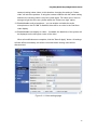
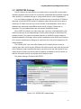
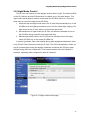
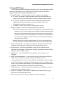
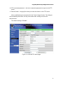
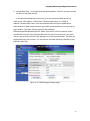
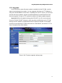
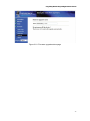
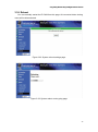
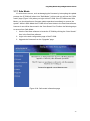
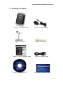
Plug & Play Wireless Day and Night NetworkCamera Table of Contents 1. INTRODUCTION..........................................................................................................................5 2. HARDWARE DESCRIPTION AND QUICK INSTALLATION/USAGE ...............................7 3. 4. 5. 2.1. M AJOR HARDWARE COMPONENTS. .....................................................................................7 2.2. QUICK INSTALLATION AND USAGE .......................................................................................8 2.3. WIRELESS CONNECTION (FOR IP CAM(W) ONLY)..............................................................12 WEB CONFIGURATION ..........................................................................................................14 3.1. INFORMATION ......................................................................................................................15 3.2. VIDEO DISPLAY ...................................................................................................................16 3.3. NETWORK ............................................................................................................................17 3.4. WIFI SECURITY (FOR IP CAM(W)) ......................................................................................19 3.5. ADVANCED NETWORK ........................................................................................................22 3.6. VIDEO SETTINGS .................................................................................................................23 3.7. 3GPP/RTSP SETTINGS .....................................................................................................23 3.8. NIGHT MODE CONTROL ......................................................................................................26 3.9. EMAIL/FTP ALARM .............................................................................................................27 3.10. NAS SETTINGS ...................................................................................................................29 3.11. SCHEDULING .......................................................................................................................31 3.12. LED DISPLAY CONTROL ....................................................................................................31 3.13. DATE/TIME ..........................................................................................................................34 3.14. ADMIN ..................................................................................................................................35 3.15. UPGRADE ............................................................................................................................36 3.16. REBOOT...............................................................................................................................38 3.17. SAFE MODE .........................................................................................................................39 3.18. SET TO FACTORY DEFAULT ...............................................................................................40 FEATURES AND SPECIFICATIONS.....................................................................................41 4.1. FEATURES ...........................................................................................................................41 4.2. SPECIFICATIONS ..................................................................................................................42 PACKAGE CONTENTS............................................................................................................44 APPENDIX A. LIST OF TESTED NAT/ROUTER DEVICES........................................................45 APPENDIX B. MAXIMUM ALLOWED VIDEO USERS.................................................................46 APPENDIX C. PERFORMANCE INFORMATION .........................................................................47 APPENDIX D. TROUBLESHOOTING .............................................................................................48 APPENDIX E. 3GPP/ISMA OPERATION .......................................................................................50 APPENDIX F. THIRD PARTY AND EMBEDDED WEB PAGE INTEGRATION ......................51 2 Plug & Play Wireless Day and Night NetworkCamera List of Figures and Tables Figure 2-1: Major components in the front panel Figure 2-2: Major components in the back panel Figure 2-3: IP CAM connection diagram. Figure 2-4: Connect Ethernet cable to a switch/router. Figure 2-5: The installation CD disk Figure 2-6: The ID/Password card Figure 2-7: Running window of CamView program Figure 2-8: Pop-up play-video password window Figure 2-9: Unplug the Ethernet cable to enable the WiFi function Figure 3-1: Open the web configuration page from CamView software Figure 3-2: IP CAM Web configuration login page Figure 3-3: IP CAM Information page Figure 3-4: Video display page Figure 3-5: Network settings page for DHCP function Figure 3-6: Network settings page for fixed IP address Figure 3-7: WiFi security disabled page Figure 3-8: WiFi security enabled page Figure 3-9: WiFi testing page Figure 3-10: Advanced network settings page Figure 3-11: Video settings page Figure 3-12: 3GPP/RTSP enabled page Figure 3-13: Night mode control page Figure 3-14: Email/FTP Alarm page Figure 3-15: NAS Storage settings page Figure 3-16: Schedule Management page Figure 3-17: Led Control settings page Figure 3-18: System date/time settings page Figure 3-19: Admin settings page Figure 3-20: Firmware upgrade settings page Figure 3-21: Firmware upgrade status page Figure 3-22: System reboot settings page Figure 3-23: System reboot under-going page Figure 3-24: Safe mode information page Figure 3-25: Stick the reset button to set to the factory default Figure 5-1: IP Camera body Figure 5-2: Power Adaptor 3 Plug & Play Wireless Day and Night NetworkCamera Figure 5-3: Bracket Figure 5-4: Antenna Figure 5-5: Quick installation guide Figure 5-6: Ethernet cable Figure 5-7: Installation CD Figure 5-8: ID/Password Card Table A-1: List of tested Wireless AP/router devices Table A-2: List of tested Wired NAT/router devices 4 Plug & Play Wireless Day and Night NetworkCamera 1. Introduction The Day & Night IP Network Camera is designed with ease-of-use firmly in mind. The camera can be easily added to a local area network, where it can be accessed within the LAN or anywhere with internet and/or phone access using the included CamView software. There is no need for complicated DNS names, firewall settings, or anything else. Just plug it in and it works. With 3GPP/ISMA support, you can view the video from the IP camera on any 3G mobile phone, any time, any place you have phone access. The special mobile phone software is designed to access the camera without the need for a fixed IP address. The video settings, including frame rate, resolution, and bandwidth, can be different for use with PC or mobile phone monitoring and viewing. For indoor surveillance and remote monitoring, the Day & Night IP Network Camera provides the best image quality and performance in its class. The Day & Night IP Network Camera also provides the best bandwidth efficiency, offering 640x480 resolution, 30 fps frame rate, and real MPEG4 image compression ability. The built-in microphone enables remote users to not only view, but also listen, to the monitored area. Equipped with a very low-light sensitive sensor and infrared LEDs, the Day & Night IP Network Camera can "see" in any lighting condition, seamlessly switching between day and night modes depending on the detected light level. The camera features a variety of storage options, including the use of Network Attached Storage devices. The software includes scheduling functions, which can activate camera recording based on a fixed time or triggered by motion detection. With a built-in web functionality, you can modify the camera can be managed from any PC or Mac using a standard web browser. The Day & Night IP Network Camera provides both wireless IEEE 802.11 b/g and wired Ethernet network interfaces for flexible installation options. It supports the WEP and WPA (Wi-Fi Protected Access) security modes to provide the best security for wireless networks. The Day & Night IP Network Camera includes a motion detection function. Users can easily setup this option and receive the alert notifications with a snapshot image through email and/or ftp whenever motion events are detected. The Day & Night IP Network Camera is ideal for a variety of personal and professional applications. 5 Plug & Play Wireless Day and Night NetworkCamera The differences It is easy to monitor the video produced by the IP Camera from anywhere in the world using the included CamView software. You do not need to remember or configure complicated network settings, such as the IP address or domain name, DDNS name, port mapping, firewall, etc. of the NAT/router devices. All you need is to have the Camera ID and Password, plus the CamView software installed on a PC or mobile device. The IP Camera is a true Plug & Play device. So, the differences between the IP Camera from Monoprice and other similar devices are as follows: Public IP address needed? No Dynamic DNS needed? No Port mapping in router? No Virtual server in router? No UPnP support in router? No What's needed? ID and Password 6 Plug & Play Wireless Day and Night NetworkCamera 2. Hardware Description and Quick Installation/Usage The IP CAM is designed to be very easy to install and use. First, let's look at the major components of the IP CAM. 2.1. Major Hardware Components The major components on the front panel of the IP CAM products are the built-in microphone, lens, IR LEDs, and status LEDs: 1. Microphone – for receiving audio/voice. Effective distance is about 16 feet (5 meters). 2. Lens – the focus of the lens is fixed, so you do not need to spend time to adjust the focus. The effective focus range is from about 12" (30 cm) to infinity. 3. IR LEDs – there are a total of 11 IR LEDs, which can provide night vision out to about 10m distance. 4. Light detector – the light detector determines the illumination level, allowing the IR LEDs to be automatically activated in low-light conditions. 5. Status indication LED (red) – this LED indicates the Internet connection status. When the Internet connection is working properly, the red LED will be steadily on. If there is any Internet connection problem, the red LED will blink repeatedly. 6. Ethernet indication LED (blue) – this LED indicates whether the Ethernet link is ok and packet traffic is being properly sent/received. When the Ethernet cable is properly connected, the blue LED is steadily on. When Ethernet data packets are being sent/received, the blue LED will blink. Figure 2-1: Major components, front view The major components on the back panel of the IP CAM products are the bracket screw jack, power jack, Ethernet jack, and reset button: 1. Bracket screw jack – this screw jack is where the mounting bracket attaches to the CAM. With the bracket you can place the IP CAM on a desk or mount it to a wall or 7 Plug & Play Wireless Day and Night NetworkCamera ceiling. 2. Power jack – this DC connector is where the external power adapter attaches to the IP CAM. The IP CAM requires a power level of 5 VDC/1.0A. Do not use any power source other than the supplied power adapter or an exact equivalent. 3. Ethernet jack – this standard RJ-45 jack is for making a wired Ethernet connection. When the Ethernet link is ok, the blue Ethernet indication LED on the front side will be steadily on (when no activity is present) or blinking (when data packets are being transferred). 4. Reset button – pressing this button resets the IP CAM to the default factory settings. The button is slightly recessed, so you will need a small object, such as a pen tip or toothpick, to press and hold the reset button for at least 4 seconds to activate the reset function. Please refer to section 3.18 for more details. 5. Antenna jack (for IP Cam(w) only) – this RP-SMA screw jack is where the wireless antenna attaches to the camera. The antenna must be properly attached for 802.11b/g wireless connectivity. However, if using only a wired connection the antenna can be left unattached. Figure 2-2: Major components, back view 2.2. Quick Installation and Usage There are only three things that you need to do to view the video from the IP CAM. 1. Connect the IP CAM to the home/office network. 2. Install the CamView software on the notebook/PC. 3. Key in the ID/password of the IP CAM (from the included ID/Password card) into the CamView software, and then you can access the camera and view video. First, connect the IP CAM to the home/office network First connect the IP CAM accessories to the IP CAM body correctly, including the antenna, bracket, power adapter, and Ethernet cable, as shown in Figure 2-3. Connect the other end of the Ethernet cable to the network, usually by plugging in to a 8 Plug & Play Wireless Day and Night NetworkCamera network switch or router, as shown in Figure 2-4. By default the IP CAM is configured to use the DHCP function and most home/office networks include a DHCP server. Therefore the IP CAM should connect to the internet immediately. The Internet status LED will be constant red when the IP CAM is properly connected to the Internet. If the LED is blinking, please refer to section 3.3-3.5 to try other network settings. Figure 2-3: IP CAM connection diagram. Figure 2-4: Connect Ethernet cable to a switch/router. Second, install the CamView software on a PC/notebook Insert the installation CD into the CD-ROM drive in your notebook or personal 9 Plug & Play Wireless Day and Night NetworkCamera computer running Microsoft Windows OS. Run the CamViewInstaller-xxx.exe installation program on the disk. The program will pop-up some windows asking about various installation options. Click the "next” button to proceed with the installation. After installation is complete, there will be a CamView icon on the desktop of your computer, double-click this icon to run the CamView software. Figure 2-5: The installation CD disk Third, use the CamView program to see the video When the CamView software starts the screen will look similar to the screen shown in Figure 2-7 below. If the computer running the CamView software is on the same local area network as the IP CAM, the CAM ID will be displayed in the Auto-Search list. For example, if the CAM ID is 001-001-029, then the Auto Search list will show the ID 001001029. If the CAM ID does not show, double-click the "Auto-Search" button to scan the network for all connected cameras. To view the video from the IP CAM, simply double-click the CAM ID in the Auto-Search list. A pop-up window will ask for the password, as shown in Figure 2-8. Enter the password found on the ID/Password Card (Figure 2-6) and click OK. Figure 2-6: The ID/Password card 10 Plug & Play Wireless Day and Night NetworkCamera Notes: 1. You can modify the password using the web configuration pages. Please refer to section 3.14 for more information. 2. You can also add the IP CAM into the CameraList in the CamView software for a more convenient video display. Please refer to the user manual of the CamView software for more information. Figure 2-7: Main window of the CamView software Figure 2-8: Pop-up window requesting the password 11 Plug & Play Wireless Day and Night NetworkCamera Viewing video in a remote location After the IP CAM has been installed and you can see the video from the CamView software in the local network, it is very easy to see the video from a remote location. All you need to do is add a camera item in the "CameraList” folder of the CamView software, then key in the IP CAM ID and Password (from the ID/Password card). Double-click the camera item to immediately begin viewing video from the IP CAM. No additional NAT/router settings modifications are needed. 2.3. Wireless Connection (for IP Cam(w) only) The IP CAM can also be connected to the network through an 802.11b/g wireless connection. There are only three steps needed to set up the wireless connection: 1. Set the WiFi security settings on the IP CAM's web configuration page. 2. Test the WiFi settings to ensure they are correct. 3. Unplug the Ethernet cable. First, set the WiFi security settings on the web configuration page. Make sure there is a WiFi router or AP on your network. Write down the WiFi security parameters used for this WiFi AP/router, including the SSID, the security mode, encryption protocols, and the "key” values. The supported WiFi security mode of the IP CAM is WEP (64 bits and 128 bits) and WPA-PSK (TKIP and AES). In most home/office WiFi environments, this is quite sufficient. The easiest way to configure the WiFi settings on the IP CAM is through the CamView software. Right-click the searched IP CAM in the "Auto Search” list and click the "Web Configure” option to open the login window of the IP CAM. Fill in all the WiFi security parameters you have written down. The WiFi configuration is complete now. Please refer to section 3.4 for more detailed description, if necessary. . Second, test the WiFi settings to ensure they are correct You can now test the above WiFi settings. Click the "WiFi test” on the "WiFi Security” settings web page. The testing result will be displayed in less than 60 seconds. If the test failed, check and re-enter the WiFi security parameters, then test again. Third, unplug the Ethernet cable If the WiFi test is successful, you can enable the WiFi connection simply by unplugging the Ethernet cable from the IP CAM. The IP CAM will detect the Ethernet 12 Plug & Play Wireless Day and Night NetworkCamera cable unplugged condition and start the WiFi connection. After the WiFi is connected, the IP CAM will connect to the Internet immediately. Notes: 1. Remember that the WiFi connection will use a different IP address, therefore you will need to do the "Auto Search” function in the CamView software again to find the IP CAM after the WiFi has connected. 2. If you want to switch back to the wired Ethernet connection, just plug the Ethernet cable into the IP CAM again. You do not need to disable the WiFi function on the web pages. Figure 2-9: Unplug the Ethernet cable to enable the WiFi function 13 Plug & Play Wireless Day and Night NetworkCamera 3. Web Configuration You can login to the web configuration page by typing the IP address of the IP CAM into a web browser. Alternatively, you can right-click the searched IP CAM in the "Auto Search” list of the CamView software and select the "Web Configure” option to open the login window of the IP CAM. Figure 3-1: Open the web configuration page from CamView software The default login User name is "admin”. Leave the Password field empty. Figure 3-2: IP CAM Web configuration login page 14 Plug & Play Wireless Day and Night NetworkCamera 3.1. Information The first page in the web configuration menu of the IP CAM is the information page. You can see the model name/firmware version, IP CAM ID, registration status, network type, and current video settings (bandwidth and resolution) on this page (see Figure 3-3). The IP CAM can be viewed remotely by the CamView software only when the IP CAM is registered. If this IP CAM is not registered, please check the Ethernet wiring of your network environment. The "Network type” field displays the network connection type (wired or wireless) and method (DHCP, PPPoE, or static IP) the IP CAM is using. The "Video users” field displays the number of connected video viewing users. Figure 3-3: IP CAM Information page 15 Plug & Play Wireless Day and Night NetworkCamera 3.2. Video Display This display page allows you to view the video display of the IP camera, as shown in Figure 3-4. For the first time use of this display on a computer, an Active-X component will be automatically downloaded into the browser. This could take some time, depending on the internet speed. The component is downloaded from a public domain, so the computer must be connected to the Internet. If you want to modify the video display screen size, please refer to section 3.6 for more details. Figure 3-4: Video display page 16 Plug & Play Wireless Day and Night NetworkCamera 3.3. Network The Network page allows you to modify the network settings of the wired Ethernet connection. The default settings use DHCP to obtain an IP address automatically. In most home and office network environments, there is a DHCP server running. In this situation, by using these default settings, the IP CAM can work immediately. If the Ethernet cable is unplugged, the IP CAM will lose connection. But as soon as the Ethernet cable is plugged in again, the IP CAM will obtain a new IP address immediately. If the network environment does not support the DHCP function you will need to configure the network settings of the IP CAM manually. Fill in all the fields including "IP address”, "Subnet mask”, "Default gateway”, and "DNS server”, to establish a network connection. All these settings must be correct for your network environment or the IP CAM will not work. The default setting is "Obtain an IP address automatically”. Figure 3-5: Network settings page for DHCP function 17 Plug & Play Wireless Day and Night NetworkCamera Figure 3-6: Network settings page for fixed IP address 18 Plug & Play Wireless Day and Night NetworkCamera 3.4. WiFi Security (for IP cam(w) only) You can connect the IP CAM to the network wirelessly, provided you have a wireless router or AP. Simply click the "Enable WiFi function” button to enable the wireless functionality. Figure 3-7: WiFi security disabled page In order to use the wireless network, you need to fill in the following fields: 1. SSID – this is the ID of the wireless router or AP in your wireless network environment. 2. Security mode – this is the security mode used by the wireless router or AP. You need to choose one of the three modes – None, WEP, or WPA-PSK: WEP: Wireless Encryption Protocol. WPA: WiFi Protected Access. PSK: Pre-Shared Key. TKIP: Temporal Key Integrity Protocol. AES: Advanced Encryption Standard. 3. WEP mode – when the WEP mode is chosen, you need to also choose between the 64-bit (5 char), 64-bit (10 hex), 128-bit (13 char), and 128-bit (26 hex) encryption modes, and then fill in the WEP key correctly. 4. WPA-PSK mode - when the WPA-PSK mode is chosen, you need to also choose between the TKIP and AES encryption modes, and then fill in the WPA-PSK key correctly. WPA2-PSK is also supported, but WPA/ WPA2 Enterprise is not. 19 Plug & Play Wireless Day and Night NetworkCamera All the fields on this page must be filled in correctly with the same settings used by the wireless router or AP. Figure 3-8: WiFi security enabled page You can also click the "WiFi test” button to check if the IP CAM can connect to the wireless network using these settings. After a successful "WiFi test" unplug the Ethernet cable to enable the wireless connection. You can click the "WiFi scan” button to scan for all the available access points nearby. If you want to use a fixed IP address with a WiFi connection, click the "IP address” button and enter in your preferred IP address. After changing settings click the "Save & Apply” button to make the changes take effect. You do not need to restart the IP CAM for the WiFi to work, just unplug the Ethernet cable. The default setting is "Disable WiFi Function”. 20 Plug & Play Wireless Day and Night NetworkCamera Figure 3-9: WiFi testing page 21 Plug & Play Wireless Day and Night NetworkCamera 3.5. Advanced Network In some special situations your network environment only provides a PPPoE connection (ADSL service), with no NAT/router available. You will then need to set the PPPoE settings on the "Advanced Network” page. Only the PPPoE username and password are needed to let PPPoE work. After the "Save & Apply” button is clicked the PPPoE function will work immediately. You can check the "Registration status” on the "Information” page to see if the IP CAM is registered using the PPPoE connection. Please be aware that the DHCP or static IP settings on the "Network” page can work alongside the PPPoE connection. However, the PPPoE has higher priority, so if the PPPoE is working, the IP CAM will use PPPoE to connect to the Internet. The default setting is "Disable PPPoE”. Figure 3-10: Advanced network settings page 22 Plug & Play Wireless Day and Night NetworkCamera 3.6. Video Settings The IP CAM is designed to provide high quality video for viewing with the CamView software. On this page, you can modify some of the settings related to video viewing: 1. Password (play video) – this is the password needed for viewing the video from the CamView software. Together with the IP CAM ID, you can view the video of this IP CAM anywhere in the world through the Internet. 2. Internet speed – this is the Internet bandwidth of your network environment. Higher values will generate higher video quality, but if your internet connection cannot provide more bandwidth than the specified value, the video quality could degrade. So, please enter a value that is lower than your internet bandwidth. 3. Select resolution & frame rate automatically – you can let the system select the most suitable video resolution and frame rate automatically. The selection is based on the "Internet speed” value. This is the recommended default setting. 4. Resolution – there are three choices: 160x120, 320x240, and 640x480. If you decide to set the value manually, be aware that if the Internet speed is too slow (low value), a high resolution (640x480) or frame rate could cause serious degradation of video quality. 5. Frame rate – the video frame display rate. Higher values mean faster movement and continuity in the video display. 6. Favor/Preference – choose between "Video motion” and "Image quality”. When the real bandwidth is insufficient for the selected "Internet speed”, the system will need to degrade the video motion or image quality. This selection determines which aspect of video quality is most important to you. 7. Brightness – the brightness of the video. A lower value means a darker display. 8. Sharpness – the sharpness of the video. A higher value means sharper video. 9. Low light sensitivity – The low light sensitivity can be normal, high, or very high. When the low light sensitivity is high, the system can produce better video clarity under low light conditions, but moving objects will lose clarity. Under very dark environmental conditions, setting the sensitivity to "very high” will get better video clarity. The default value of this setting is "high”. 10. Video color – choose between "colored” and "black&white”. 11. Video flip – the video output can be inverted for situations in which the camera is mounted upside down, such as on a ceiling. 12. Outdoor/Indoor video – for better video display quality, set this to the appropriate value for the environment in which the camera will be used. The default setting is "Outdoor video”, which in most cases is also ok for indoor usage. Under some special cases, there could be some strip lines on the video display when the IP 23 Plug & Play Wireless Day and Night NetworkCamera camera is taking indoor video. In this situation, changing the setting to "Indoor video” will solve the problem. If using the camera outdoors with the indoor setting selected, the resulting video is very blurry and vague. For indoor use, if there is strong sun light into the room, please select the "Indoor+sun light” option. 13. Enable/disable audio microphone – you can enable or disable the audio microphone on the IP CAM. If disabled, there will be no voice In the CamView video display. 14. Enable/disable time display on video – if enabled, the date/time of the system will be displayed on the left-upper corner of the video. When all modifications are complete, click the "Save & Apply” button. All settings will take effect immediately, but all the connected video viewing users will be disconnected. Figure 3-11: Video settings page 24 Plug & Play Wireless Day and Night NetworkCamera 3.7. 3GPP/RTSP Settings The IP CAM can be viewed from any mobile device running iOS or the Android operating systems with minimum 3G connectivity (bandwidth directly affects received video quality). For detailed settings on using mobile devices, refer to Appendix E. You can enable or disable the ability of mobile devices to access the IP CAM on this page. If the 3GPP/RTSP feature is disabled, mobile devices will not be able to access the IP CAM, even with the correct Camera ID and password. When this is disabled, the rtsp stream with MPEG2 audio will still function. Please refer to Appendix F for more details about the rtsp stream with MPEG2 audio. When 3GPP is enabled, the video frame rate, resolution, and bandwidth for 3G mobile access can be set independently from the video settings for CamView (PC) software access. The maximum allowed resolution is 352x255 and the maximum allowed bandwidth is 256 kbps. When audio is enabled for both 3GPP and CamView (PC), and the video/audio is displayed in CamView, the audio will be disabled in 3G mobile displays. The "Access URL” line is the URL address for 3G mobile phone to input for viewing video from the IP camera. Different 3G mobile devices may need to input this URL in different areas. Detailed information can be found in the user manual of your mobile device. Please note that a public IP address is needed for the IP camera, so that the 3G mobile devices can access the IP camera's video. The default setting is "Enable 3GPP/RTSP”. Figure 3-12: 3GPP/RTSP enabled page 25 Plug & Play Wireless Day and Night NetworkCamera 3.8. Night Mode Control The IP Cam can function in both daylight and the dark of night. The infrared LEDs on the IP CAM can provide IR illumination for objects up to 10 meters distant. This night mode control page is used to control when the IR LEDs will be on. There are three ways to control the night mode (IR LEDs): 1. Automatic day and night mode switch: the IP cam will automatically turn on the IR LEDs when the lighting conditions are too low for natural light imaging. The light sensor on the IP cam allows it to detect the light levels. 2. Scheduled time of night mode: the IP Cam can also be scheduled to turn on the IR LEDs during a specific time range each day. 3. Manual night mode control: the IP Cam can be manually forced into night mode (IR LEDs on) or day mode (IR LEDs off). In order to get better video color display during both daylight and darkness, there is an ICR (IR Cutter Remover) inside the IP Cam. This ICR automatically to filters out any IR (Infrared) light during the daylight conditions and allows the IR light to pass through during the hours of darkness. This ensures that the video color quality is excellent, especially when compared to other IP cameras. Figure 3-13: Night mode control page. 26 Plug & Play Wireless Day and Night NetworkCamera 3.9. Email/FTP Alarm The IP CAM has a built-in Email/ftp functionality, which can automatically send an email with a jpg image or push a jpg image to an ftp site whenever an alarm is triggered. The related settings are explained below: 1. Email/FTP trigger – choose between "motion”, "schedule”, and "disable” A. If "motion” is selected, it means that when there is a motion detected, the system will send out the email and/or ftp with the captured video snapshot. B. If "schedule” is selected, it means that the email/ftp alarm detection and triggering will be active according to a preset schedule. Refer to the "scheduling” instructions in section 3.11. C. If "disable” is select, there will be no email/ftp alarm activity. 2. Motion sensitivity – there are three possible choices in this field. "High” sensitivity means that an alarm will be triggered if a moving object larger than about 1% of the entire video area is detected. Note that the real size of the object is not important. What matters is the size of the moving object in relation to the rest of the video display area. A small pencil moving close to the camera could trigger the motion detection, while a large car moving far away could go unnoticed. "Median" sensitivity has a size threshold about 3% of the video display area. "Low” sensitivity has a size threshold of about 10% of the video display area. 3. Send email message – if this option is enabled, the IP CAM will send an email message with the jpeg picture attached to the specified email account. 4. Email recipient – input the email address to which the IP CAM will send a detection notice message. The email will include a jpg image file named with the date/time that the trigger occurred. 5. SMTP server – this is the SMTP server that will be used to send the mail message. 6. SMTP username/password – this is the email account information used by the SMTP server to transfer the email message. The SMTP server and username/password account are only needed for transferring an email message to the "Email recipient”. Note that the "Email recipient” can be on another email server or any reachable email address. The username and password fields can be left empty if no authentication is needed for the SMTP server. 7. SMTP server test – after the settings are completed, click "SMTP server test” to check that all the settings are correct. 8. Send FTP message – if this option is enabled the IP CAM will send out a jpg picture file to the specified ftp account. 9. FTP server – this is the FTP server address to receive the jpeg file. 27 Plug & Play Wireless Day and Night NetworkCamera 10. FTP username/password – this is the username/password to login into the FTP server. 11. Remote folder – the jpeg file will be put under this folder on the FTP server. When modifications are complete click the "Save & Apply” button. The changes will immediately take effect, but any connected video viewing users will be disconnected. The default setting is "Disable”. Figure 3-14: Email/FTP Alarm page 28 Plug & Play Wireless Day and Night NetworkCamera 3.10. NAS Settings The IP Camera has the ability to record video files to any standard NAS (Network Access Storage) device. The IP camera connects to the NAS device using the standard LMX_NS/CIFS/SSN protocols, which are the same as the Microsoft Windows network neighborhood protocols. This ability turns a standard NAS into a NVR (Network Video Recorder) device. Note: when the IP camera is performing NAS recording it counts are one video user. Please refer to Appendix B for more information about the maximum number of video users. 1. If the "Always Recording” option is selected, the system will start to record to the NAS storage device immediately and will continue to record until the NAS device is full or recording is turned off. If the "Schedule Recording” option is selected, the system will perform NAS recording according to the preset schedule, as explained in section 3.11. The "Disable Recording” option disables NAS recording. 2. When NAS recording is taking place the system will check the free disk space of the NAS device. If the free disk space is less than the specified number, the system will do "Circular recording” (overwrite the oldest recorded files of this IP CAM on the NAS device) or will "Stop recording”, as selected. If the "Keep recorded video for xx days” option is selected, the system will do circular recording and over write any recorded video files older than xx days. 3. The IP camera can connect to the NAS device by using the "NAS name” or "NAS IP address”. If the NAS device and the IP camera are in the same local area network, the IP camera can automatically locate and connect to the NAS device using the "NAS name”. If the NAS device uses a fixed IP address (either in the local area network or in the public internet), the IP camera can connect to it by using the "NAS IP address” option. 4. The "Shared folder name” is the folder on the NAS device in which recorded video files by this IP CAM will be stored. 5. The "NAS access account” and "NAS access password” are the username and password needed to login to the specified "Shared folder name” on the NAS device. 6. NAS Scan – use this option to scan for specific NAS devices in the local area network. Not all the NAS devices are supported for this scan function. 7. NAS Info – displays the NAS storage capacity and available disk space. 8. Configure NAS (web) – click this to connect to the web configuration page of the NAS device. You will need to enter the login username/password of the NAS device. 29 Plug & Play Wireless Day and Night NetworkCamera 9. Access NAS files – on the Microsoft Windows platform, click this to button access the files on the NAS devices. In the Microsoft Windows environment, you can access the NAS device by entering the URL address \\”NAS name”\”shared folder name” or \\”NAS IP address”\”shared folder name” into the Windows Internet Explorer address bar, followed by the "NAS access account” and "NAS access password” into the pop-up login window. The video files are stored in the subfolder IPCamRecordFiles/Recording/ID-ID, where ID is the ID of this IP camera. All the recorded files use the naming format hhmmss.crf, where hh is the hour, mm is the minute, and ss is the second of the starting time of the recorded video. The files are segmented every five minutes. You can use the included CamPlay software to play back the video files. Figure 3-15: NAS Storage Settings page 30 Plug & Play Wireless Day and Night NetworkCamera 3.11. Scheduling The IP Camera includes the ability to schedule the activation of motion detection triggered email/ftp alerts and/or NAS recording, using the individual parameters set in the "Email/ftp alarm settings" and the "NAS settings” pages. A total of 12 periods and events can be scheduled. However, there is no automatic event conflict checking, so if scheduled periods overlap, the IP CAM will perform all scheduled functions. To schedule Email/ftp alerts and/or NAS recording, the "Schedule” option must enabled in the "Email/ftp alarm settings" and/or the "NAS settings” pages. 1. Schedule list – all scheduled events are listed here. Each listed item can be modified or deleted by clicking the "Edit” or "Delete” button. 2. Email/ftp Alarm – for each scheduled event, if this option is selected and the "Motion triggered” option is enabled, the IP camera will trigger the email/ftp alert during the scheduled time period whenever video motion is detected. 3. NAS Record – for each scheduled event, when this option is selected you can also select either the "Continuous” or "Motion triggered” options. The "Continuous” option means that the IP CAM will perform the video recording to the NAS device during the entire scheduled period. The "Motion triggered” option means that the IP CAM will perform video recording to the NAS device for 30 seconds during the scheduled period, each time that video motion is detected. 4. For the scheduling period option you can choose between "Every week”, "Every day”, or "Fixed time” options: A. The "Every week” option allows you to set the days of the week and the times of each day during which alerts/recording will take place. B. The "Every day” option allows you to set the time during which alerts/recording will take place each day. C. The "Fixed time” option allows you to set a starting and ending date and time, during which alerts/recording will take place. 31 Plug & Play Wireless Day and Night NetworkCamera Figure 3-16: Schedule management page 32 Plug & Play Wireless Day and Night NetworkCamera 3.12. LED Display Control The IP CAM provides an LED Display Control function, with which you can enable or disable the LED indicators on the front panel of the IP CAM. The related settings are explained below: 1. Normal LED display – select this option to enable the Status and Ethernet LED displays. 2. Turn off LED display always – select this option to disable the Status and Ethernet LED displays at all times. 3. Turn off LED display after network connected – when this option is selected the LED will only display when the Internet connection has some problem. The LED display will be off as long as a good Internet connection is maintained. Figure 3-17: LED Control settings page 33 Plug & Play Wireless Day and Night NetworkCamera 3.13. Date/Time The IP CAM can synchronize its internal clock with the universally available time server (for example stdtime.gov.tw) through NTP protocol. The date/time will then always be accurate as long as the IP CAM is connected to the Internet. You can choose your local TimeZone so that the time will display correctly. For some TimeZone areas, the "Daylight Saving Time” option can be enabled or disabled. When the "Daylight Saving Time” option is enabled, the starting and ending time of the Daylight Saving Time can be edited. Figure 3-18: System date/time settings page 34 Plug & Play Wireless Day and Night NetworkCamera 3.14. Admin The Admin page controls access to the IP CAM through the web interface. Here you can modify the account username and password, which are required to access the web interface. If you forget your login information, you can reset the IP CAM to the factory default values, but will lose all your other settings. Refer to section 3.18 for instructions on performing a reset to factory defaults. Please note that this account information is different from the video play password on the "Video settings” page. Figure 3-19: Admin settings page 35 Plug & Play Wireless Day and Night NetworkCamera 3.15. Upgrade In the event that a newer firmware update is available for this IP CAM, use this page to load and apply the update. You can upgrade either from an FTP address or using a file downloaded to a local drive. If updating from an FTP server, you will need to know the server address, account username/password, and the filename of the firmware upgrade. During an FTP update the system will display update progress. Important! While the update is taking place DO NOT turn off or remove power from the IP CAM. DO NOT attempt to make any other modifications to the IP CAM settings until the update is completed and the IP CAM has rebooted. If the update process is interrupted the IP CAM could enter into "Safe Mode" (see section 3.17 for more information about Safe Mode). Figure 3-20: Firmware upgrade settings page 36 Plug & Play Wireless Day and Night NetworkCamera Figure 3-21: Firmware upgrade status page 37 Plug & Play Wireless Day and Night NetworkCamera 3.16. Reboot You can manually restart the IP CAM from this page. All connected video viewing users will be disconnected. Figure 3-22: System reboot settings page Figure 3-23: System reboot under-going page 38 Plug & Play Wireless Day and Night NetworkCamera 3.17. Safe Mode If a critical error occurs, such as damaging the firmware by interrupting the update process, the IP CAM will reboot into "Safe Mode". In this mode you will see the "Safe mode” page (Figure 3-24) when you login to this IP CAM. If the IP CAM enters Safe Mode, you should perform a firmware update operation immediately to recover the system. While in Safe Mode the IP CAM will not send video to the CamView software, however it can still be discovered in the "Auto Search" list. Perform the following steps to recover from Safe Mode: 1. Use the CamView software to locate the IP CAM by clicking the "Auto Search” item in the CamView software. 2. Login to the web configuration page of the IP CAM. 3. Upgrade the firmware from the "Upgrade” page. Figure 3-24: Safe mode information page 39 Plug & Play Wireless Day and Night NetworkCamera 3.18. Set To Factory Default If you forget your password or want to erase all information from the IP CAM, you can reset all the settings back to where they were when the IP CAM left the factory. To do this, simply press and hold the reset button on the back of the IP CAM for at least 4 seconds, then release it. This should be done while the IP CAM is powered on. The IP CAM's settings will be reset to factory defaults and it will automatically reboot. After a successful reset the web login account username will be "admin” and there will be no login password. Also, the play-video password will be "ipcam” after a reset to factory default. Figure 3-25: Stick on the reset button to set to the factory default 40 Plug & Play Wireless Day and Night NetworkCamera 4. Features and Specifications 4.1. Features Easily access the camera from anywhere in the world via the ID/password No complicated NAT/router settings needed Free video management software - CamView program included for easy access and multi-camera management 3GPP/ISMA support Dual video streaming with separate frame rate/resolution/bandwidth settings for PC and mobile IR LED control – supports automatic, manual, and scheduled modes Built-in Web server for management using a standard web browser Supports enhanced MPEG-4 compression Supports resolution of up to 640x480 pixels, 30 frames per second View video from your Wireless or wired Ethernet network 802.11b/g WiFi security supports WEP and WPA-PSK (TKIP and AES) (IP Cam(w) only) Supports PPPoE protocol for direct ADSL connection Motion Detection and E-mail/FTP notification with attached jpeg image file Synchronize the date/time settings using the NTP protocol Connect up to 20 users simultaneously (please see appendix B for limitations) Built-in microphone for synchronized audio Event scheduling NAS storage access Online Firmware upgrade, will enter safe mode when power is lost during critical firmware upgrade point Watchdog function to prevent system failure 41 Plug & Play Wireless Day and Night NetworkCamera 4.2. Specifications Models IP Camera Power DC 5V, 1A Processors RISC CPU, hardware video processing and compression. Network interface Ethernet 10BaseT/100BaseTX, Auto-MDIX, RJ-45 Wireless interface IEEE 802.11g 6 - 54 Mbps IEEE 802.11b 1 - 11 Mbps Transmit power: 14.5dBm typically @ 802.11g 17.5dBm typically @ 802.11b Receiver sensitivity: 54Mbps: Typical -73dBm @ 10% PER 11Mbps: Typical -86dBm @ 10% PER Modes: Infrastructure and ad-hoc Antenna gain: 1.8 dBi Image sensor RGB VGA 1/4 inch CMOS Automatic exposure control, automatic white balance, automatic gain control, automatic brightness control. Light sensitivity 0.2 Lux ( IR LED off ) 0 Lux (with 10 meters IR LEDs on) Automatically turn on the IR LED in low light environment. Lens 4.5 mm, F1.9, viewing angle: 55.6°, fixed iris. focus range: 30 cm to infinity Day & night IR lens Motor controlled IR-cut filter (ICR). Buttons One reset button, to factory default settings Indicators One LED for internet connection status indication One LED for Ethernet connection indication Video compression MPEG-4 Part 2 (ISO/IEC 14496-2) with motion detection, profiles: Simple Profile, level 0-3 Resolutions 160x120, 320x240, 640x480 Frame rate Up to 30 fps in all resolutions Video streaming MPEG-4 Separate frame rate/resolution/bandwidth settings for PC and mobile. Image settings Resolution: VGA(640x480), QVGA(320x240), QQVGA(160x120) Bandwidth: 64k, 128k, 256k, 512k, 768k, 1M, 1.2M, 1.5M 42 Plug & Play Wireless Day and Night NetworkCamera bps Frame rate: 1~5, 10, 15, 20, 25, 30 fps Audio Built-in microphone for audio monitoring Audio compression: MPEG2 audio, AMR-NB for 3GPP/ISMA Security Web management username/password protection Video display ID/password protection WiFi WEP and WPA security mode Installation, Installation tool on CD and Web-based configuration management and Automatic configuration backup and restore maintenance Video management software-CamView for video access and multi-camera management Firmware upgrades via FTP Minimum Web Built-in web server for standard web browser access browsing and Pentium 4 CPU 1.0 GHz or higher, or equivalent AMD management 1GB RAM software requirements Supported protocols IPv4, HTTP, TCP, ICMP, RTSP, RTP, UDP, IGMP, RTCP, SMTP, SNTP, FTP, DHCP, UPnP, ARP, DNS, PPPoE, etc. Accessories Power adaptor, camera bracket, RJ45 Ethernet cable, quick (included) installation guide, CD with installation tool/software and User's Manual, ID/Password card, antenna (for IP Cam(w)). Video management Surveillance application for viewing and archiving up to 16 software cameras Users Up to 20 simultaneous unicast users (please see appendix B) Unlimited users using multicast Alarm and event Events triggered by video motion detection management Notification/upload of JPEG images over FTP and/or email Dimensions (HxWxD) 4.9" x 3.0" x 1.4" (125 x 75 x 35 mm), 9.9 oz. (280 g), and weight incl. camera bracket, excl. power adaptor Approvals CE, FCC Part 15 Subpart B Class B Wireless RF - CE, FCC Part 15 Subpart C Power supply: FCC, UL EN 60950 Operating conditions Temperature: +32 ~ +122°F (0 ~ +50°C) Humidity: 20 - 80% RH (non-condensing) 43 Plug & Play Wireless Day and Night NetworkCamera 5. Package Contents Figure 5-1: IP Camera body Figure 5-3: Bracket Figure 5-2: Power Adaptor Figure 5-4: Antenna Figure 5-5: Quick installation guide Figure 5-6: Ethernet cable Figure 5-7: Installation CD Figure 5-8: ID/Password Card 44 Plug & Play Wireless Day and Night NetworkCamera Appendix A. List of Tested NAT/Router Devices The following tables list the tested NAT/router devices that are known to work with the IP CAM and the CamView software, when viewing in a remote location. You do not need to do any modifications to the default settings of these NAT/routers. In some office environments, if some a strict firewall function is enabled, it is possible that you cannot view the IP CAM video through the firewall router. In this situation, please contact your MIS person to solve the problem. Brand name Model name Asus WL-550gE Belkin P5D7230-4 Buffalo WHR-G54S Buffalo WHR-HP-G54 Corega CG-WLBARGO D-Link DI-524 LanTech WL54G-BR Linksys WRT54G Netgear WNR834B PCi BLW-HPMM SMC SMCWBR14-G2 ZyXEL P-334WH Table A-1: List of tested Wireless AP/router devices Brand name Model name AboCom CAS5047 ASUS RX3041 Buffalo BBR-4HG Corega CG-BARSD DLink DI-604 Edimax BR-6104K LanTech HR-114Pro Lemel LM-IS6500 PCi BRL-04R ZyXEL Prestige-334 Table A-2: List of tested Wired NAT/router devices 45 Plug & Play Wireless Day and Night NetworkCamera Appendix B. Maximum Allowed Video Users The maximum number of allowed simultaneous video users for a single IP Camera is dependent on the video settings, including the "Internet speed” and video resolution. The following tables are a summary of the maximum allowed video users with the various options enabled or disabled: Note: when the IP camera is performing NAS recording, it is counted as one video user. 1. When audio is disabled. For video resolution of 160x120 pixels Frame rate\bandwidth 64k ~ 512k 1M ~ 1.5M 5fps ~ 30 fps 20 4 For video resolution of 320x240 pixels Frame rate\bandwidth 64k ~ 256k 512k 768k 1M ~ 1.5M 5fps ~ 30 fps 20 18 9 4 For video resolution of 640x480 pixels 2. Frame rate\bandwidth 512k 768k 1M ~ 1.5M 5fps ~ 30 fps 8 6 4 When audio is enabled. For video resolution of 160x120 pixels Frame rate\bandwidth 64k ~ 256k 512k 1M ~ 1.5M 5fps ~ 30 fps 20 14 4 For video resolution of 320x240 pixels Frame rate\bandwidth 64k ~ 256k 512k 768k 1M ~ 1.5M 5fps ~ 30 fps 20 12 8 4 For video resolution of 640x480 pixels Frame rate\bandwidth 512k 768k ~ 1.2M 1.5M 5fps ~ 30 fps 6 4 3 46 Plug & Play Wireless Day and Night NetworkCamera Appendix C. Performance Information 1. Video Performance Information The video quality is dependent on the video parameter settings and the network quality. If you want to have a better video quality, you will usually want to set a higher resolution and a higher frame rate. This is fine when you are viewing the video locally in the same network, but when you want to see the video remotely through the Internet, you need to know the Internet speed (bandwidth) of your network. If the "Internet speed” setting of your IP camera is very large, but your real Internet speed (bandwidth) is relatively low, the video quality could be very bad. In some worst case scenarios, the video display could be disconnected entirely. For the best video quality you should have broadband service from your ISP and should set the "Internet speed” of the IP CAM a little lower than the real Internet speed provided by your ISP. Note that when multiple users are displaying the video from the same IP CAM at the same time, the video bandwidth times the number of users will be needed for the Internet speed. 2. WiFi Performance Information The WiFi performance is dependent on the distance between the IP camera and the AP (Access Point) / router and is dependent on the number of wireless devices connected to the AP/router. Performance can also be affected by the presence of any barriers (e.g., floors, walls, etc.) between the IP CAM and the AP/router. If there is any outdoor space between the IP CAM and the AP/router, be aware that wireless performance can also be affected by rain or other adverse environmental conditions. Another factor affecting wireless performance is the antenna gain and directionality in relation to the AP/router. In general, if the IP camera is set to the default video setting (256k bps) and there are no other interferences between the IP CAM and the AP/router, the effective straight-line distance is about 100 meters between IP CAM and the AP/router. 47 Plug & Play Wireless Day and Night NetworkCamera Appendix D. Troubleshooting 1. What does the flashing red LED on the front of the IP camera indicate? A: When the IP Cam is connected to the Internet and working correctly, the red LED light will be on constantly. If the red LED light is flashing, it is probably due to some network connecting problem. Please check the network connection settings and make any necessary changes. 2. When the IP Cam is connected to the network through the wireless connection, the video quality is poor, how can I fix this problem? A: When the IP Cam is connected using the wireless network and the video quality is poor, it is because the available bandwidth is insufficient. This could be caused by too great a distance between the IP Cam and the wireless AP (Access Point) or router or by having too many wireless clients connected to the AP/router. The use of a high-gain wireless antenna can improve distance related bandwidth issues, while disconnected unnecessary clients can reduce the load on the wireless AP/router. If all else fails, the use of a physical wired connection to the IP CAM will eliminate wireless bandwidth issues. 3. Can I adjust the effective focus of the IP Cam? A: The focus of the IP Cam is fixed to an effective distance about 12" (30 cm) to infinity. In almost all circumstances this will result in clear video with no need to adjust the focus. 4. What is the viewing angle of the IP Cam? A: The viewing angle of the IP Cam is about 60 degrees. 5. To what maximum distance can the IP Cam "see"? A: When using the IP Cam to see a long-distance object, the clarity depends on the size of the object. Usually if your eyes can see something clearly in that distance, the IP Cam can also see that object clearly at about the same distance. 6. What should I do if the password is forgotten and the ID/password card is lost or otherwise missing? A: The easiest way to solve this problem is to reset the IP Cam to the factory default. Use a pen or toothpick to press and hold the reset button on the rear panel of the IP Cam for more than 4 seconds and then release it. The IP Cam will restart to the factory default settings. The default account username is "admin” and there is no password. The default video-play password is "ipcam”. You can adjust these values by using a browser to login to the IP Cam and perform the necessary modifications. 48 Plug & Play Wireless Day and Night NetworkCamera 7. What should I do if I cannot hear the audio from the IP Cam? A: There is a microphone inside the IP Cam. If you can see the video from the accompanied CamView software, but cannot hear the audio, check the following: (1). Check that the speakers on your computer are powered on and have a sufficient volume level by playing some other audio file. (2). Check if the microphone on the IP Cam is enabled. Login to the web configuration page of the IP Cam or open the "video settings” in the CamView software, select the "video” settings, and click the "Enable audio microphone” option. 8. I can see the video in a remote location, but the video quality is poor. Sometimes the video will disconnect and then reconnect again by itself. What is the cause of the problem? A: It is probably because the internet bandwidth (internet speed) is insufficient. You can either purchase a faster internet connection from your ISP or can decrease the bandwidth settings of the IP CAM using either the web configuration page or the CamView software. 9. Does the IP Cam provide a recording function? A: Yes, you can record the video/audio of the IP Cam using the CamView software. You can also perform video/audio recording to a standard NAS storage device. Use the CamPlay software to playback the recorded video/audio files. 10. Can I connect the IP camera directly to my PC/notebook with an Ethernet cable? A: If the IP camera is directly connected to your PC/notebook computer using an Ethernet cable, the IP camera will automatically use an IP address (called "auto IP”) of 169.254.xxx.xxx. If your PC/notebook computer is configured to DHCP, it will also use an "auto IP” address, but it will take about one minute after the IP camera is connected to the computer and you need to make sure that the WiFi interface on your PC/notebook computer is disabled. After about one minute, you can run the CamView software to access the IP camera, the CAM ID should be displayed in the "auto-search” list. You can then view the video by double clicking the CAM ID icon. Be aware that in this configuration, other local or remote computers cannot access the IP CAM or view the video from it. 49 Plug & Play Wireless Day and Night NetworkCamera Appendix E. 3GPP/ISMA Operation 3GPP/ISMA operation uses the RTSP protocol for 3G mobile devices to display the video stream from some network devices, including the IP camera. The IC202w supports the RTSP protocol and the video/audio codecs needed by 3GPP/ISMA. You only need to access the address rtsp://ip_cam_address/CAM_ID.password on the 3G mobile device to access the video of the IP camera. No additional configuration is required on the IP camera. Note that "ip_cam_address" is the public IP address of the IP camera, "CAM_ID" is the unique Camera ID of the specific IP camera, and "password" is the video play password of the specific IP camera (detailed in section 3.6). Different 3G mobile devices may require different operations to enter the RTSP address. Please contact the 3G mobile device's customer service for more details. The video quality and resolution is the same value as set on the "video settings” page. Since the bandwidth provided by the 3G service is less than 256kbps, it is recommended to configure the "Internet speed” of the IP camera to 128k or 64k bps. Note 1: when the audio microphone is enabled on the IP camera, if the "Internet speed” in "video settings” page is larger than 256k or the resolution is 640x480, the audio will be disabled for 3GPP/ISMA access. In all other cases, the 3G mobile device will be able to hear the audio from the IP camera. Note 2: when the audio microphone is enabled on the IP camera, if there is any 3G mobile access to the IP camera with audio enabled, there will be no audio in the CamView software window for this IP camera. iPhone users please download the MonoCam app from iTunes App Store. 50 Plug & Play Wireless Day and Night NetworkCamera Appendix F. Third Party and Embedded Web Page Integration For third party and embedded web page integration, the IP Camera supports the standard RTSP protocol and video/audio codecs needed by most popular video playback software, including Apple QuickTime and VideoLAN. The supported media protocols include TCP and UDP. The IP Camera will automatically use TCP or UDP media streaming, depending on the connection request. The video codec supported is MPEG4 and the supported audio codecs are AMR-NB and MPEG2-audio. The access methods are as following: rtsp://ip_cam_address/CAM_ID.password.mp2 for MPEG4 video + MPEG2 audio rtsp://ip_cam_address/CAM_ID.password for MPEG4 video + AMR-NB audio where "ip_cam_address" is the IP address of the IP camera, "CAM_ID" is the unique Camera ID of the specific IP camera, and "password" is the video play password of the specific IP camera (detailed in section 3.6). You can modify the password of the IP camera to prevent others from viewing the video. For embedded web page integration, add the following code into the proper position of the desired web page: <object classid="clsid:5C519EC4-2BAE-44CE-B7F5-AD0CCD4BEFBD" id="mpeg4ax" codebase="http://www.starvedia.com/ActiveX/axmpeg4.cab#Version=0,0,0,0" width="320" height="240"> <param name="Src" value=" rtsp://ip_cam_address/CAM_ID.password.mp2"> </object> 51