1
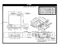
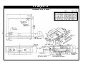
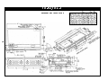
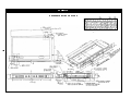
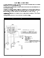
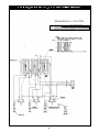
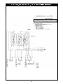
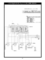
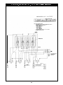
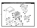
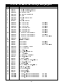
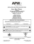
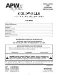
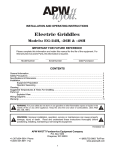
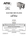
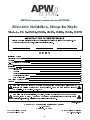
R INSTALLATION AND OPERATING INSTRUCTIONS Electric Griddles, Drop-In Style Models: EGD-1824, 1836, 1848, 2436, 2448, 2472 Please complete this information and retain this manual for the life of the equipment. For Warranty Service and/or Parts, this information is required. Model Number Serial Number Date Purchased CONTENTS 2 Installation Cutouts 7 Electrical Connections General 13 U.L. Conditions Of Acceptability 13 Layout 13 Installation 13 Owners Information 15 Cleaning The Griddle After Uncrating 15 Controls 15 Seasoning The Griddle Surface 15 Operating Instructions 15 Care & Cleaning 15 Parts Lists & Exploded Views 16 Warranty 20 ! ! WARNING: For your safety do not store or use gasoline or other flammable vapors or liquids in the vicinity of this or any other appliance. Keep the area free and clear of combustibles. (See ANZI Z83.14B, 1991) WARNING: Improper installation, operation, service or maintenance can cause property damage, injury or death. Read and understand these instructions thoroughly before positioning, installing, maintaining or servicing this equipment. ! ! P/N 88057-10 9/05 APW WYOTT Foodservice Equipment Company P.O. Box 1829 Cheyenne, WY 82003 +1 (307) 634-5801 Phone +1 (800) 752-0863 Toll Free +1(307) 637-8071 Fax www.apwwyott.com 1 U.L. CONDITIONS OF ACCEPTABILITY A. This equipment must be installed in an all metal fixture of steel or stainless steel construction, .078 inch thick minimum for the top and supporting frame. Side enclosure to be at least 22 MSG minimum thickness. B. A removable bottom enclosure must be provided under each drop-in unit and be made of metal construction of at least 22 MSG min. If ventilating openings are provided in the bottom enclosure they must not allow the entrance of a 3/4 inch diameter rod nor be located directly below uninsulated live terminals. C. Minimum spacing between griddle top edge and adjacent items should be: Fixture back wall 1-3/4 inch, Fixture side enclosure 1 inch, Front control panel 7/8 inch, Other drop-in devices 1 inch. D. Controls shall be mounted on the front vertical surface of the fixture. E. For supply connections use wire suitable for at least 90 degrees Celsius (194 degrees Fahrenheit). NOTES: 1. Griddle can be mounted with the trough in the front or rear, dimensions shown are for front trough mounting, for rear trough mounting this dimension must be between 7/8" and 2". 2. Table top reinforcement and gasket furnished with the griddle. 3. Electrical connection box factory located in the front position, the connection box can be moved to the rear location shown. IMPORTANT: 4. Any dimension smaller than the minimum or larger than the maximum shown in the table will require corresponding changes by the fabricator to the grease chute by adding an extension, etc. to prevent the grease from spilling into the cabinet. 5. Any dimensions smaller than minimum given will require additional panels or sides and back to facilitate servicing. 6. The minimum dimension from the back of the control panel to the front of the griddle top is 7/8" regardless of the shape of the bullnose or table overhang. 7. Griddles are shipped from the factory with dimension "D" at 7-7/16". Moveable braces permit the fabricator to easily vary this dimension up to 10-7/16" in increments of 3/4". 8. The minimum space between adjacent griddles must be 1-5/8" and between any other combination of drop-in cooking equipment must be 1". 9. Electrical wiring crossing the tray slide is to be placed under the tray slide and not above it. 10. The installer or servicer must put the electrical wiring near the control panel inside the wire guide before attaching the control panel to the fixture front. IMPORTANT STEPS IN INSTALLATION: ! ! Griddle position to be no closer than 7/8" from component frame edge and control panel. Install the gasket between the griddle top and the table top before clamping. Exercise caution so that the griddle top does not pinch or damage the gasket. 2 EGD-1824 REFERENCE NOTES ON PAGE 2 EGD-1836, EGD-2436 REFERENCE NOTES ON PAGE 2 EGD-1848, EGD-2448 REFERENCE NOTES ON PAGE 2 EGD-2472 REFERENCE NOTES ON PAGE 2 ELECTRICAL CONNECTIONS WARNING: Electrical and grounding connections must comply with the applicable portions of the national electrical code and/or other local electrical codes. WARNING: Disconnect electrical power supply and place a tag at the disconnect switch indicating that you are working on the circuit. Terminal Box Location. As indicated in Fig. 1, the terminal boxes can be located at either the left front or the right rear of the griddle. When shipped from the factory, the device has the terminal box attached in the left front position. The box can be relocated to the alternate position by removing two screws. . Loading. Electrical loadings of the griddles covered by this instruction are tabulated on the appropriate wiring diagram. Fusing. Griddle is not fused and must be connected to a properly fused circuit. EGD-1824, 208/240/480VAC, 1 & 3 Phase (Wiring Diagram) 7 EGD-1836, 208/240/480VAC, 1 & 3 Phase (Wiring Diagram) 8 EGD-2436, 208/240/480VAC, 1 & 3 Phase (Wiring Diagram) 9 EGD-1848, 208/240/480VAC, 1 & 3 Phase (Wiring Diagram) 10 EGD-2448, 208/240/480VAC, 1 & 3 Phase (Wiring Diagram) 11 EGD-2472, 208/240/480VAC, 3 Phase (Wiring Diagram) 12 GENERAL Drop-In Griddles are designed to be installed into metal fixtures or fabricated tops. Fixture or top must be sufficiently rigid to support device weight without warping. Emphasis is on simplifying the layout and fabrication. These instructions covers all models. The floor plans for the griddles shows overall and other key dimensions of the device and their relationships to the fixture or top into which they will be installed. U.L.CONDITIONS OF ACCEPTABILITY: A. This equipment must be installed in an all metal fixture of steel or stainless steel construction, .078 inch thick minimum for the top and supporting frame. Side enclosure to be at least 22 MSG minimum thickness. B. A removable bottom enclosure must be provided under each drop-in unit and be made of metal construction of at least 22 MSG min. If ventilating openings are provided in the bottom enclosure they must not allow the entrance of a 3/4 inch diameter rod nor be located directly below uninsulated live terminals. C. Minimum spacing between griddle top edge and adjacent items should be: fixture back wall 1-3/4 inch, Fixture side enclosure 1 inch, Front control panel 7/8 inch, Other drop-in devices 1 inch. D. Controls shall be mounted on the front vertical surface of the fixture. E. For supply connections use wire suitable for at least 90 degrees Celsius (194 degrees Fahrenheit). LAYOUT 1. The layouts illustrate the holes to be cut into the metal fixture or fabricated top to accept the griddle. Also shown are holes to be cut into the fixture front (apron) to accommodate the griddle control panel. The front-to-back (depth) dimensions for the griddles are not the same. Before making the initial cuts into the fixture, make sure that the model number you are referring to corresponds with the model number on the griddle nameplate. 2. All minimum dimensions shown must be met. 3. After making the proper layout, cut the hole in the top of the fixture. 4. Cut the large hole and drill the control panel holes in the front of the fixture from the layout. 5. The griddle is furnished with a stiffening angle or reinforcement frame assembly that is used to reinforce the fixture top. This reinforcement must be welded on the perimeter of the counter top cutout. The upturned flanges on the reinforcement should be located an equal distance from the sides of the cut-out. Figure #2 shows a cutaway view of how the stiffening angle appears when welded to the fixture top. NOTE: (1) Before welding the stiffening angle to the fixture top, assemble the furnished clamps and clamp screws as shown in figure #2. (2) Place one clamp in each of the frame assembly slots. Do not tighten the screw. INSTALLATION With all the large holes cut out, the smaller control panel holes drilled, and the stiffening angle welded into place, the fixture is now ready to receive the griddle. 13 1. Hobart furnishes a gasket or seal that must be placed around the perimeter of the hole in the top as shown in Fig. 3. This gasket may be temporarily held in place with tape. Do not place the staple securing the gasket ends on or near a corner. 2. A number of clamps, such as the one shown in Fig. 3, appear at intervals along the perimeter. Pull clamps outward so that the griddle frame clears them when it is dropped into place. 3. Drop the griddle into position by lowering it into the fixture top hole. Make sure that the thermostat capillaries are not kinked or pinched when setting the griddle in place. With the griddle in place, the gasket or seal becomes compressed. See Fig. 4. 4. Slide the clamp inward so that it engages the upper part of the protruding angle from the griddle body frame. See Fig. 5. Slide the clamp sideways so that the notch on it locks against the reinforcement angle. This prevents the clamp from sliding out. 5. Tighten the clamp screws against the angle as shown in Fig. 5. This tightening forces the clamp to press down on the griddle body frame extension. The griddle top is now drawn close to the fixture top, compressing the gasket and forming an effective grease guard. Tighten at least one screw on each side before tightening all screws. Do not exceed 60 in.Ibs. torque when tightening bolts. 6. Slide the tray slide (grease drawer receptacle) through the cut-out hole on the apron or front of the fixture, resting it on the two "U braces. 7. Mount the thermostats to the control panel and make the pilot light connections per the accompanying making any nameplate wiring electrical voltage diagram. Before connections, (located on check tray slide under grease drawer) to ensure it matches voltage being applied. 8. Set the control panel in place and screw it to the apron, using the 1/2" long thread-forming screws. 9. Pull the tray slide against the back of the control panel and secure it appropriate screws. 10. 14 Slide the grease drawer into place. with the OWNER'S INFORMATION CLEANING THE GRIDDLE AFTER INSTALLATION Before using the griddle for the first time, be sure to remove the factory-applied rust preventive compound. Add a mild detergent to hot water and wash the griddle well. Rinse with a clean, damp cloth and wipe dry. CONTROLS The heat of the griddle surface is controlled by turning the dial knobs (recessed in the front control pane!). Separate signal lights cycle with each control, whenever the thermostat calls for heat the signal light associated with it will be on. Each thermostat controls twelve inches of griddle surface width. The thermostat temperature range is 200-450 degree Fahrenheit, +/- 10 degrees. SEASONING THE GRIDDLE SURFACE After a thorough cleaning, the griddle is ready for seasoning. Preheat the griddle to 400 degrees Fahrenheit. When the dialed temperature is reached as indicated by the signal lights going off, spread a light film of cooking oil or fat over the entire surface of the griddle. After two minutes, wipe the griddle clean of excess oil. Repeat this operation. The griddle is now ready for use. OPERATING INSTRUCTIONS 1. Preheat the griddle (preheat time for 77-350 degree Fahrenheit is approximately 8 minutes) - Set the thermostat dials at the correct temperature for the food to be cooked. A red light will flash on automatically for each section of the griddle when the thermostat is set, and will go off when the section has reached the set temperature. The signal light will flash on and off during the cooking operation to show that correct temperature is being maintained. You are now ready to load the griddle. 2. Load the griddle - After preheating, load the griddle and cook according to recipe. 3. Economy hint - Turn the griddle OFF (or to the lowest thermostat setting) during idle periods. CARE AND CLEANING At the end of each day's operation, turn all temperature controls to "OFF". After each cooking load, scrape the griddle surface with scraper or rigid spatula to remove excess fat and food particles. Once a day or whenever necessary, thoroughly clean and wipe out the grease trough. As necessary during use, wipe out accumulated material to provide good drainage. Remove grease drawer, empty and wash. In general, soap and water with the aid of a sponge or soft cloth will clean the drawer thoroughly. Wipe clean with a damp cloth and dry. Clean control panel with a damp cloth and dry. Each week or whenever necessary, clean griddle thoroughly. If desired, use a pumice or griddle stone over surface. Rub with the grain of the metal while still warm. Avoid steel wool! After each thorough cleaning, the cooking surface must be re-seasoned. To remove the control knobs for cleaning, pull straight out. Wash in soapy water. Rinse, dry, and replace on shaft. 15 EGD-1824, EGD-1836 & EGD-1848 (Exploded View) 17 18 22 16 20 15 14 1 2 21 3 23 24 9 4 19 27 28 25 8 7 13 10 12 27 26 5 22 27 29 29 11 22 6 PARTS LIST ITEM 1 PART NUMBER DROP-IN ELECTRIC GRIDDLES, EGD-1824, -1836, -1848 DESCRIPTION 1439722 HEATING ELEMENT, 208 VOLT 1439723 HEATING ELEMENT, 240 VOLT 2 64256301 PRESSURE PLATE 3 64257301 BULB CLAMP ASSEMBLY 4 64634001 BAFFLE 5 64257801 TERMINAL BLOCK BOX 6 64257901 COVER 7 1126035 TERMINAL BLOCK 8 64258101 BOTTOM PANEL FOR -1824 64258201 BOTTOM PANEL FOR -1836 64258301 BOTTOM PANEL FOR -1848 64767903 BRACE ASSEMBLY FOR -1824 64767904 BRACE ASSEMBLY FOR -1836 64306601 BRACE ASSEMBLY FOR -1848 64258501 CONTROL PANEL ASSEMBLY FOR -1824 64258502 CONTROL PANEL ASSEMBLY FOR -1836 64258501 CONTROL PANEL ASSEMBLY 2 EACH FOR -1848 11 64262514 KNOB ASSEMBLY 12 1513903 INDICATOR LIGHT 13 3110082 PANEL SEAL FOR -1824 3110084 PANEL SEAL FOR -1836 3110082 PANEL SEAL 2 EACH FOR -1848 14 64252201 TRAY ASSEMBLY FRONT 15 64260301 TRAY ASSEMBLY 16 64408801 BAFFLE, R.H. 17 64409001 TRAY SLIDE ASSEMBLY 18 64408805 BAFFLE, L.H. 19 64463502 THERMOSTAT ASSEMBLY 20 8211100 SCREW, 1/4-20 X 3/4 21 8431500 HEX NUT, 1/4-20 22 8196300 SELF TAPPING SCREW, 10-32 X ½ 23 3110130 SCREW, 10-32 X 1/2 24 8417100 HEX NUT, 10-32 25 8141300 SELF TAPPING SCREW, 8-32 X ½ 26 8436400 WING NUT, 5/16-18 27 8519500 FLATWASHER, 5/16 28 8431700 HEX NUT, 1/4-20 29 8436200 HEX NUT, 5/16-18 30 642626-01 GASKET, GRIDDLE TOP (Not Shown) FOR 1824 642626-03 GASKET, GRIDDLE TOP (Not Shown) FOR 1836 642626-05 GASKET, GRIDDLE TOP (Not Shown) FOR 1848 9 10 17 EGD-2436, EGD-2448 & EGD-2472 (Exploded View) 10 12 13 9 8 20 21 1 23 11 24 22 22 28 30 29 27 5 28 30 25 7 22 27 26 6 4 18 17 16 22 2 3 19 15 14 PARTS LIST ITEM 1 PART NUMBER DROP-IN ELECTRIC GRIDDLES, EGD-2436, -2448, -2472 DESCRIPTION 1439725 HEATING ELEMENT, 208 VOLT 1439726 HEATING ELEMENT, 240 VOLT 2 64256701 PRESSURE PLATE 3 64257301 BULB CLAMP ASSEMBLY 4 64625100 BAFFLE 5 64257801 TERMINAL BLOCK BOX 6 64257901 COVER 7 1126035 8 64258202 TERMINAL BLOCK BOTTOM PANEL FOR -2436 64739201 1 EACH FOR -2448 64739401 1 EACH FOR -2448 FOR -2472 64258401 9 64767904 BRACE ASSEMBLY FOR -2436 FOR -2448 64306601 FOR -2472 64335603 10 64258502 CONTROL PANEL ASSEMBLY FOR -2436 64258501 2 EACH FOR -2448 64258505 1 EACH FOR -2472 1 EACH FOR -2472 64258506 KNOB ASSEMBLY 11 64262514 12 1513903 INDICATOR LIGHT 13 3110084 PANEL SEAL FOR -2436 3110082 2 EACH FOR -2448 3110083 2 EACH FOR -2472 14 64252201 TRAY ASSEMBLY FRONT 15 64260302 TRAY ASSEMBLY 16 64408804 BAFFLE, R.H. 17 64409002 TRAY SLIDE ASSEMBLY 18 64408803 BAFFLE, L.H. 19 64463502 THERMOSTAT ASSEMBLY 20 8211100 SCREW, 1/4-20 X 3/4 21 8431500 HEX NUT, 1/4-20 22 8196300 SELF TAPPING SCREW, 10-32 X ½ 23 3110130 SCREW, 10-32 X 1/2 24 8417100 HEX NUT, 10-32 25 8141300 SELF TAPPING SCREW, 8-32 X ½ 26 8436400 WING NUT, 5/16-18 27 8519500 FLATWASHER, 5/16 28 8431700 HEX NUT, 1/4-20 29 8436200 HEX NUT;- 5/16-18 30 8519600 FLATWASHER, 1/4 31 642626-04 GASKET, GRIDDLE TOP (Not Shown) FOR 2436 642626-06 FOR 2448 642626-07 FOR 2472 19 APW WYOTT EQUIPMENT LIMITED WARRANTY APW Wyott Foodservice Equipment Company warrants it's equipment against defects in materials and workmanship, subject to the following conditions: This warranty applies to the original owner only and is not assignable. Should any product fail to function in its intended manner under normal use within the limits defined in this warranty, at the option of APW Wyott such product will be repaired or replaced by APW Wyott or its Authorized Service Agency. APW Wyott will only be responsible for charges incurred or service performed by its Authorized Service Agencies. The use of other than APW Wyott Authorized Service Agencies will void this warranty and APW Wyott will not be responsible for such work or any charges associated with same. The closest APW Wyott Authorized Service Agent must be used. This warranty covers products shipped into the 48 contiguous United States, Hawaii, metropolitan areas of Alaska and Canada. There will be no labor coverage for equipment located on any island not connected by roadway to the mainland. Warranty coverage on products used outside the 48 contiguous United States, Hawaii, and metropolitan areas of Alaska and Canada may vary. Contact the international APW Wyott distributor, dealer, or service agency for details. Time Period One year for parts and one year for labor, effective from the date of purchase by the original owner. The Authorized Service Agency may, at their option, require proof of purchase. Parts replaced under this warranty are warranted for the un-expired portion of the original product warranty only. Exceptions *Gas/Electric Cookline: Models GCB, GCRB, GF, GGM, GGT, CHP-H, EF, EG, EHP. Three (3) Year Warranty on all component parts, except switches and thermostats. (2 additional years on parts only. No labor on second or third year.) *Broiler Briquettes, Rock Grates, Cooking Grates, Burner Shields, Fireboxes: *Heat Strips: *Glass Windows, Doors, Seals, Rubber Seals, Light Bulbs: Models FD, FDL, FDD, FDDL. 90 Day Material Only. No Labor. Two (2) Year Warranty on element only. 90 Day Material Only. No labor second year. No Labor. In all cases, parts covered by extended warranty will be shipped FOB the factory after the first year. Portable Carry In Products Equipment weighing over 70 pounds or permanently installed will be serviced on-site as per the terms of this warranty. Equipment weighing 70 pounds or under, and which is not permanently installed, i.e. with cord and plug, is considered portable and is subject to the following warranty handling limitations. If portable equipment fails to operate in its intended manner on the first day of connection, or use, at APW Wyott's option or its Authorized Service Agency, it will be serviced on site or replaced. From day two through the conclusion of this warranty period, portable units must be taken to or sent prepaid to the APW Wyott Authorized Service Agency for in-warranty repairs. No mileage or travel charges are allowed on portable units after the first day of use. If the customer wants on-site service, they may receive same by paying the travel and mileage charges. Exceptions to this rule: (1) countertop warmers and cookers, which are covered under the Enhanced Warranty Program, and (2) toasters or rollergrills which have in store service. Exclusions The following conditions are not covered by warranty: *Equipment failure relating to improper installation, improper utility connection or supply and problems due to ventilation. *Equipment that has not been properly maintained, calibration of controls, adjustments, damage from improper cleaning and water damage to controls. *Equipment that has not been used in an appropriate manner, or has been subject to misuse or misapplication, neglect, abuse, accident, alteration, negligence, damage during transit, delivery or installation, fire, flood, riot or act of god. *Equipment that has the model number or serial number removed or altered. If the equipment has been changed, altered, modified or repaired by other than an Authorized Service Agency during or after the warranty period, then the manufacturer shall not be liable for any damages to any person or to any property, which may result from the use of the equipment thereafter. This warranty does not cover services performed at overtime or premium labor rates. Should service be required at times which normally involve overtime or premium labor rates, the owner shall be charged for the difference between normal service rates and such premium rates. APW Wyott does not assume any liability for extended delays in replacing or repairing any items beyond its control. In all cases, the use of other than APW Wyott Authorized OEM Replacement Parts will void this warranty. This equipment is intended for commercial use only. Warranty is void if equipment is installed in other than commercial application. Water Quality Requirements Water supply intended for a unit that has in excess of 3.0 grains of hardness per gallon (GPG) must be treated or softened before being used. Water containing over 3.0 GPG will decrease the efficiency and reduce the operation life of the unit. Note: Product failure caused by liming or sediment buildup is not covered under warranty. THE FOREGOING WARRANTY IS IN LIEU OF ANY AND ALL OTHER WARRANTIES EXPRESSED OR IMPLIED INCLUDING ANY IMPLIED WARRANTY OF MERCHANTABILITY OR FITNESS FOR PARTICULAR PURPOSES AND CONSTITUTES THE ENTIRE LIABILITY OF APW WYOTT. IN NO EVENT DOES THE LIMITED WARRANTY EXTEND BEYOND THE TERMS STATED HEREIN. 9/05 20