1
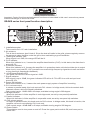
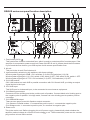
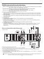
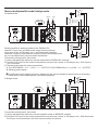
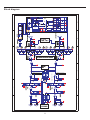
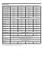
-20
-10
-8
-80
CH1
dB
-6
0
-1
-3
-5
PROT
CLIP
-5dB
-10dB
SIG
BRG PAR
ON
-20
-10
-8
GRAVIS 24
CH2
dB
-6
0
-1
-3
-5
Professional Power Amplifier
User's Manual
English
GRAVIS SERIES
CONTENTS
Important precautions........................................................................................................................2
GRAVIS series front panel and function description............................................................................3
GRAVIS series rear panel and function description.............................................................................4
GRAVIS series connections set up ....................................................................................................5
Protection circuits .............................................................................................................................7
Ex-factory settings ............................................................................................................................7
Use environment ..............................................................................................................................7
Applications .....................................................................................................................................7
Block diagram...................................................................................................................................8
Specifications ...................................................................................................................................9
GRAVIS series dimensions .............................................................................................................10
1
IMPORTANT PRECAUTIONS
1.Read all documentation before operating your equipment.
2.Retain all documentation for further reference.
3.Mains voltage must correspond to rear unit label.
4.Damages caused by connecting to improper AC voltage are not covered by any warranty.
5.Always operate the unit with the AC ground wire connected to the electrical system ground.
Precautions should be taken to avoid equipment faulty, improper or inefficient grounding.
6.After connection to power supply Standby LED is lit, showing that some components inside are
already powered.
7.Do not connect any amplifier channel output into another channel input. Do not connect in parallel or
series an amplifier output with any other amplifier output.
8.In system setup, amplifier's output power should be 50% greater than loudspeaker(s) rated handling
power.
9.Make sure the signal is correctly connected to amplifier input channel following current input mode.
10.Please turn off the power switch when extracting the power cord and signal cable, or adjusting the
input mode switch.
11.In order to split one signal to more than one amplifier, we suggest to use a signal distributor.
12.In typical use, please set the volume to -0dB position.
13.If you need to supply power to more than one unit power amplifiers,to eliminate the big surge current
interference to electricity net, and preventing the voltage fluctuate abnormal when simultaneously
switching on the amplifiers, we recommend you use the sequence power procedure.
14.Do not obstruct the air entrance and exit ports.
2
Important: Control functions and adjustment functions not described in this user's manual may cause
mechanical danger or electrical shock.
GRAVIS series front panel function description:
ON
GRAVIS 62
-6
-5
-8
-3
-1
-20
-80
dB
PROT
CLIP
-5dB
-10dB
SIG
BRG PAR
ON
0
-6
-5
-8
-3
-10
OFF
-1
-20
-80
CH1
dB
0
CH2
1. Installation socket
To be used to fix in 19" rack installation.
2. Air entrance
This is the air entrance, don't block it. Since the dust will settle in the grille, please regularly remove
the screws to clean the filter under the grille, thus maintaining a good ventilation.
3. -5dB signal indicator LED
When signal is at -5dB, this orange LED will be lit.
4. CLIP indicator
When this indicator is on, it means the amplifier has distortion (CLIP). In this status, the distortion is
around 0.5%.
5. Protection Indicator
When this indicator is lit, it means the amplifier is in protection status, which should be due to output
short-circuit, over-heat,DC, VHF (constant non-musical high frequency signal due to self-excitation
or long time high-frequencies feedback).
6. -10 dB signal indicator LED
This green LED will be lit when signal at -10dB.
7. Signal indicator
With signal is up to -22dB, the green indicator LED will be lit. This LED is on with an input level
around 0.35V.
8. Power ON Indicator
When this indicator is on, it means the main power supply system of amplifier is working.
9. CH1 volume control
In stereo or parallel mode: this knob controls CH1 volume. In bridge mode, this knob controls both
channels volume, while CH2 knob is disabled.
Gain control range: -80dB~0dB in 40 steps, available turning angle is 280 degree.
10.Bridge indicator
When this indicator is lit the amplifier is on bridge mode, as set by rear panel dip switches.
11.Parallel indicator
When this indicator is lit the amplifier is on parallel mode, as set by rear panel dip switches.
12.CH2 volume control
In stereo or parallel mode, this knob controls CH2 volume. In bridge mode, this knob is inactive, the
amplifier volume is controlled by CH1 knob only.
Gain control range: -80dB~0dB in 40 steps, available turning angle is 280 degree.
13.Power Switch
This switch is used to turn power on and off. Press the upper part to switch ON, and lower part to
switch OFF.
3
GRAVIS series rear panel function description:
CH1 LINK
CAUTION
RISK OF ELECTRIC SHOCK
DO NOT OPEN
CH1 OUTPUT
CH1 INPUT
!
ATTENTION: RISQUE DE CHOC ELECTRIQUE - NE PAS OUVRIR
WARNING:TO REDUCE THE RISK OF FIRE OR ELECTRIC
INPUT SENSITIVITY
SHOCK DO NOT EXPOSE THIS EQUIPMENT TO RAIN OR MOISTURE
3
E
F US
T12AL 250V
CAUTION:
REPLACE ONLY WITH
SAME TYPE FUSE!
CH1
4
3
CH2
2
1
32dB 1.0V
0.775V
OPERATION MODE
PARALLEL
BRIDGE STEREO
4
3
3
CH1
CH2 ON
~230V/50Hz/4500W
2
1
CH2 LINK
CH2 INPUT
CH2 OUTPUT
Made in China under license of MONTARBO ELETTRONICA S.r.l - ITALY
E
F US
OFF
SOFT
CLIPPING
1. Fuse holder(230V)
This fuse holder contains a standard fuse, which is used to protect amplifier from damages. If the
amplifier is connected to power supply but Power ON LED is not lit, please check the fuse status.
If you found the fuse broken, you must replace it with a same specification fuse.
2. Air exit
This part is the air exit. Don't obstruct it.
3. Input sensitivity selection by dip switches, with three settings:
Whole system signal gain 32dB - CH1 switches (3-4) ON; CH2 switches (1-2) ON.
Whole system signal gain 1.0V CH1 switch 4 ON, switch 3 OFF; CH2 switch 2 ON, switch 1 OFF.
Whole system signal gain 0.775V CH1 switches (3-4) OFF; CH2 switches (1-2) OFF.
4. CH1 LINK socket
CH1 LINK socket is a male XLR in parallel connection with CH1 female XLR, providing an output
signal similar to the input.
5. CH1 XLR input
This XLR input is a balanced input, to be connected to sound source equipment.
6. CH1 Binding post output
Connect red color binding post to the positive pole of speaker. Connect black color binding post to
the negative pole of speaker. In bridge mode, connect red color binding post to speaker positive
connector.
7. CH1 SPEAKON output
There are two ways to use this Speakon output connector:
1) In Stereo or Parallel modes: 1+ connects the positive pole; 1- connects the negative pole.
2) In Bridge mode: 1+ connects to positive pole, 2+ connects to negative pole.
8. Power cord
This is the mains cord. Before plugging it to a AC power supply, please kindly check whether the
amplifier marked voltage is conform to local voltage or not. Then connect the power cord to a mains
4
plug conform to local mains socket.
GRAVIS series rear panel function description:
9. Operation mode selector by dip switches allows three settings:
1)Stereo mode: dip switches 3 and 4 are OFF-OFF - CH1 and CH2 have independent inputs and outputs.
Two channels volume are independently controlled.
2)Parallel mode: dip switch 3 is OFF, and 4 is ON CH1 and CH2 use CH1 input signal.
Two channels volume are independently controlled.
3)Bridge mode: dip switches 3 and 4 are ON - CH1 and CH2 use CH1 input signal.
The volume will be controlled by CH1 knob only.
10. Soft clip selector/ DIP Switches 2-1
1) With dip switch 2 is ON and CH1 input signal overloads, the circuit will smoothly limit the waveform.
2) With dip switch 1 is ON and CH2 input signal overloads, the circuit will smoothly limit the waveform.
11. CH2 LINK socket
CH2 LINK socket is male XLR in parallel connection with CH2 female XLR, providing an output signal
similar to the input.
12. CH2 XLR input
This XLR input is a balanced input, to be connected to sound source equipment.
13. CH2 Binding post output
Connect red color binding post to the positive pole of speaker. Connect black color binding post to
the negative pole of speaker.
In bridge mode, connect red color binding post to speaker negative connector.
14. CH2 SPEAKON output
In Stereo or Parallel modes connect the SPEAKON output to the loudspeaker as follows: 1+ to the
positive pole, 1- to the negative pole.Setting the amplifier to bridge mode, this connection is no
longer active.
1-
-
OR
(OUT)
1.Stereo mode
+
-
4
3
+
CH1 LINK
CAUTION
1+
(IN)
STEREO
RISK OF ELECTRIC SHOCK
DO NOT OPEN
+
Stereo mode/parallel mode/ bridge mode
CH1 OUTPUT
CH1 INPUT
!
ATTENTION: RISQUE DE CHOC ELECTRIQUE - NE PAS OUVRIR
WARNING:TO REDUCE THE RISK OF FIRE OR ELECTRIC
INPUT SENSITIVITY
SHOCK DO NOT EXPOSE THIS EQUIPMENT TO RAIN OR MOISTURE
3
E
F US
T12AL 250V
CAUTION:
REPLACE ONLY WITH
SAME TYPE FUSE!
CH1
4
3
CH2
2
1
32dB 1.0V
0.775V
OPERATION MODE
PARALLEL
BRIDGE STEREO
4
3
3
CH1
CH2 ON
~230V/50Hz/4500W
OFF
SOFT
CLIPPING
2
1
CH2 LINK
CH2 INPUT
CH2 OUTPUT
Made in China under license of MONTARBO ELETTRONICA S.r.l - ITALY
+
-
+
1+
(IN)
-
OR
+
(OUT)
Connection procedure for this mode:
11) Using rear panel dip switches, set the mode to 'STEREO';
2) CH1 and CH2 inputs are independently connected to CH1/CH2 (L/R) outputs of sound source
(such as a mixer, CD player, etc.).
3) There are two ways for output connection:
A. CH1 SPEAKON(1+/1-)= CH1(+/-)OUTPUT, CH2 SPEAKON = (1+/1-) = CH2(+/-)OUTPUT;
B. Binding post outputs.
Attention: Before plugging the input signal connectors please turn the volume to the minimum to
avoid any noise, which should damage the connected speakers.
5
Stereo mode/parallel mode/ bridge mode
+
-
4
3
+
CH1 LINK
CAUTION
1+
(IN)
PARALLEL
RISK OF ELECTRIC SHOCK
DO NOT OPEN
+
2.Parallel mode
(OUT)
1-
-
OR
CH1 OUTPUT
CH1 INPUT
!
ATTENTION: RISQUE DE CHOC ELECTRIQUE - NE PAS OUVRIR
WARNING:TO REDUCE THE RISK OF FIRE OR ELECTRIC
INPUT SENSITIVITY
SHOCK DO NOT EXPOSE THIS EQUIPMENT TO RAIN OR MOISTURE
3
E
F US
T12AL 250V
CAUTION:
REPLACE ONLY WITH
SAME TYPE FUSE!
CH1
4
3
CH2
2
1
32dB 1.0V
0.775V
OPERATION MODE
PARALLEL
BRIDGE STEREO
4
3
3
CH1
CH2 ON
2
1
OFF
SOFT
CLIPPING
~230V/50Hz/4500W
CH2 LINK
CH2 INPUT
CH2 OUTPUT
Made in China under license of MONTARBO ELETTRONICA S.r.l - ITALY
+
-
1+
Setting amplifier's working mode to the "PARALLEL",
1channel 1 input only is linked to the output of sound source
1+
(such as a mixer, a CD player, etc.), and feeds both amplifier
channels. Anyway, both channels volume controls are independent,
OR
so you can adjust each volume control as desired.
1Connection procedure for this mode:
1) Using rear panel dip switches, set the amp mode to 'PARALLEL' position.
2) Connect CH1 input to the output of sound source (such as a mixer, a CD player, etc.); CH2 input is
not connected.
3) There are two ways for output connection:
A. CH1 SPEAKON(1+/1-)=CH1(+/-)OUTPUT, CH2 SPEAKON=(1+/1-)=CH2(+/-)OUTPUT;
B. Binding post outputs.
+
-
Plugging the input signal connector, please turn the volume knobs to the minimum to avoid any
noise, which should damage the connected speakers.
-
3.Bridge mode
OR
(IN)
4
3
CH1 LINK
CAUTION
RISK OF ELECTRIC SHOCK
DO NOT OPEN
2+
+
+
-
BRIDGE
+
(OUT)
1+
-
CH1 OUTPUT
CH1 INPUT
!
ATTENTION: RISQUE DE CHOC ELECTRIQUE - NE PAS OUVRIR
WARNING:TO REDUCE THE RISK OF FIRE OR ELECTRIC
INPUT SENSITIVITY
SHOCK DO NOT EXPOSE THIS EQUIPMENT TO RAIN OR MOISTURE
3
E
F US
T12AL 250V
CAUTION:
REPLACE ONLY WITH
SAME TYPE FUSE!
CH1
4
3
CH2
2
1
32dB 1.0V
0.775V
OPERATION MODE
PARALLEL
BRIDGE STEREO
4
3
3
CH1
CH2 ON
~230V/50Hz/4500W
OFF
SOFT
CLIPPING
2
1
CH2 LINK
CH2 INPUT
CH2 OUTPUT
Made in China under license of MONTARBO ELETTRONICA S.r.l - ITALY
Connection procedure for this mode:
1) Using rear panel dip switches, set the amplifier mode to 'BRIDGE' position.
2) Connect CH1 input to the output of sound source (such as a mixer, a CD player, etc.). With this mode,
CH2 input is not connected, and CH2 volume control is inactive.
6
Protection circuits
1. CLIP/Limit
This feature has two protection functions:
1) Limiting the input signal level to prevent input signal overloading beyond amplifier rated input level,
thus causing square wave output damaging the speaker.
2) When the signal waveform distorts, it can automatically adjust gain and limit distorted signal output.
Note: If input signal is +22dBu (10V) even clip limit will be helpless, so do not increase input source
signal unlimitedly.
2. Soft clip
This function can be selected by rear panel ON/OFF dip switches. When the input signal exceeds the
set range, it will smoothly limit the input waveform range.
3. Overheat protection
1) When the amplifier works at full load for a long time, fans could reach higher speed. If this condition
continues and the amplifier transistor temperature rises to 95 degrees, the first-step power decrease
(halving output power) will be activated, to ensure that even overheating still there's program output.
Power reduction according to different music content, amplifier will be recovered to be original output
power in 3-10 minutes.
2) When the amplifier works for long time in overload, without ventilation or external temperature higher
than 35 degrees,the amplifier is in the first phase of power reduction and no eased, the amplifier
transistor temperature rises to 105 degrees, the fully protection will be activated and no signal will be
output. In this condition, the PROT (protection) LED and temperature LED are simultaneously on.
Suggestion: Do not connect to the amplifier loads under 4 ohms, don't place the amplifier in
high-temperature environment and without air flow.
4. VHF protection
If the amplifier output has reached a certain level and large amount of frequencies exceeding 10KHz,
like a mic feedback, then the amplifier may go into VHF protection after 3 seconds. In this case the PROT
(protection) LED on the front panel will be lit, the amplifier will have no output, but it will be recovered
automatically after 10 seconds protection circuit activation. If the output signal does not change , the VHF
protection will continue to be active.
5. Short-circuit protection
All our company Gravis series amplifiers are provided of short-circuit protection. This protection makes the
output transistors working in a safe range. When output is in short-circuit, the PROT (protection) LED on
the front panel will be lit and the amplifier has no output. The amplifier will be recovered 10 seconds after
the end of short-circuit removal.
6. AC Power Supply Protection
If the AC mains voltage is lower than the minimum allowed working voltage (~165V), the power supply will
be automatically turned off until when the mains voltage returns in regular range.
7. DC protection
1) In order to protect the speaker, the DC protection circuit will be activated, when the output signal has
large DC voltage (=2.6V). In this case the PROT (protection) LED on the front panel will be lit, and the
amplifier will have no output.
2) If there is DC output and the relay circuit is open, there's a protection circuit to force the amplifier output
to burn the fuse to protect the speakers.
Ex-factory settings
1. All the volume adjustment knobs were set at "-80dB" position.
2. Power switch was set "OFF".
3. Soft clip dip switches set "ON".
4. Working mode selector dip switches set at "STEREO" place.
5. Sensitivity selector dip switches set at "0.775V" place.
Use environment
1. The room temperature shall be kept around 25 degree when used indoor. The amplifier can't be used
at too high temperature environment or such temperature may cause components damages due to
over-heat.
2. If used outdoor, please avoid sunshine and rain damped, or it would shorten equipment's life.
3. a. Environment temperature: -10°C~40°C
b. Relative humidity: less than 90%
c. Air pressure: 80kPa~106kPa
Applications
Gravis series has been designed for live concert, disco, night club, etc.
7
Block diagram
32dB/1.0V/0.775V
32dB/1.0V/0.775V
32dB/1.0V/0.775V
8
Specifications
MODEL
GRAVIS 24
GRAVIS 30
GRAVIS 46
GRAVIS 62
8Ω stereo power*
450Wx2
650Wx2
850Wx2
1200Wx2
4Ω stereo power*
750Wx2
1100Wx2
1400Wx2
2000Wx2
2Ω stereo power**
1150Wx2
1400Wx2
2300Wx2
3000Wx2
8Ω bridge power*
1600W
2280W
3000W
4100W
4Ω bridge power**
2550W
3200W
4600W
6500W
ITEM
20Hz-20KHz@8Ω,(+/-0.5dB)
Frequency response
THD+N(THD%)
<0.1%
<0.1%
<0.1%
<0.1%
Slew rate
20V/us
20V/us
20V/us
20V/us
Damping factor
(@100Hz)
>200
>200
>200
>200
Dynamic range
≥80dB
≥80dB
≥80dB
≥80dB
S/N rate
≥90dB
≥90dB
≥90dB
≥90dB
32dB/1.0V/0.775V
32dB/1.0V/0.775V
32dB/1.0V/0.775V
32dB/1.0V/0.775V
38dB
38dB
38dB
38dB
Input Sensitivity
Voltage gain
Input Impedance
Output circuit class
Protection
Bal 20K/Unbal 10K
Class 2H
Class 2H
Class 3H
Soft start, short circuit, overload, DC, over-heat, THD clip/limit, output volume increase
gradually function after switch on, lack of voltage of SMPS, VHF, infrasound frequency
protection, over-power limit, output power will be limited if over-heat
Airflow from front panel to rear panel.
Cooling air-flow
Power voltage
frequency
Gross weight
Class 3H
~230V±10%/50-60Hz
12Kg
12Kg
Power has been tested under EIAJ standard @ 230V.
9
15Kg
16Kg
GRAVIS series dimensions:
Front panel
ON
89mm
GRAVIS 62
-6
-6
-5
-8
PROT
CLIP
-5dB
-10dB
SIG
BRG PAR
ON
-3
-1
-20
-80
-3
OFF
-1
-20
0
dB
-5
-8
-80
CH1
dB
0
CH2
483mm
Rear panel
CH1 LINK
CAUTION
RISK OF ELECTRIC SHOCK
DO NOT OPEN
INPUT SENSITIVITY
3
E
F US
CH1 OUTPUT
CH1 INPUT
!
ATTENTION: RISQUE DE CHOC ELECTRIQUE - NE PAS OUVRIR
WARNING:TO REDUCE THE RISK OF FIRE OR ELECTRIC
SHOCK DO NOT EXPOSE THIS EQUIPMENT TO RAIN OR MOISTURE
T12AL 250V
CAUTION:
REPLACE ONLY WITH
SAME TYPE FUSE!
89mm
CH1
4
3
CH2
2
1
32dB 1.0V
0.775V
OPERATION MODE
PARALLEL
BRIDGE STEREO
4
3
3
CH1
CH2 ON
~230V/50Hz/4500W
2
1
OFF
SOFT
CLIPPING
CH2 LINK
CH2 INPUT
CH2 OUTPUT
Made in China under license of MONTARBO ELETTRONICA S.r.l - ITALY
430mm
Side panel
76mm
GRAVIS 24/GRAVIS 30:355mm
GRAVIS 46/GRAVIS 62:464mm
10
38mm