1
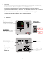
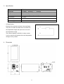
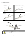
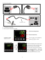
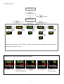
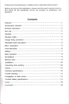
Solder Wire Pre-Heater
YPH-10
Operation Manual
Thank you for purchasing the YPH-10.
Read these instructions thoroughly for proper use of this device.
Make sure to read "Safety Notes" before you use the device.
This information protects you from possible dangers during use.
Apollo Seiko Ltd.
Safety Notes
This manual includes the important information to use the device safely. This also includes useful information to
prevent avoiding injury or damaging property.
Please read this manual carefully prior to connecting or operating the YPH-10
Keep this manual nearby the device all the time.
Supply only specified voltage
Do not connect to a power supply greater than the specified voltage. If not, electrical shock and /or damage to the
device may occur.
Make sure that the electrical outlet is properly grounded. If the outlet is not properly grounded, electrical shock
and/or damage to the device may occur.
Working ambient temperature and relative humidity
This device has been designed to use between 0~40 degree、10%~90%. Do not use this device under the
condition exceeding here-in.
Handle with care
This device is designed to pre-heat the solder wire.
Please be careful not to touch the heated solder wire. It may cause burns.
Please make sure to turn off the power, when you set or replace the solder wire.
Please handle the device with care. If you drop or make a big impact/ vibration, it may cause malfunction.
If you do not use the machine for a long time
Please turn off the power, remove the power cable and keep it dry and cool place.
If you note malfunction on unit
If the device become a malfunction, turn off the power immediately and contact a dealer you purchased the
device from.
Immunity from responsibility
We do take NO responsibility on a damage caused by misuse, mistake, accident, uses in abnormal condition or
natural disaster such as an earthquake, a fire etc.
We do take NO responsibility on contingency loss (Business loss、Business stop) caused by device stop.
We do take NO responsibility on a loss caused by the operation not mentioning on this manual.
We do take NO responsibility on a loss caused by a wrong connection with other equipment.
If for any reason the internal circuitry is tampered with altered or repaired without written consent of Apollo Seiko,
the warranty is null and void.
The customer is allowed to make necessary tooling adjustment, replace solder
wire and make any necessary adjustments to the temperature controller.
・
2
INDEX
1.
Introduction ................................................................................................................. 4
2.
Description .................................................................................................................. 4
3.
Specification ................................................................................................................ 5
4.
Dimension ................................................................................................................... 5
5.
Installation and Connection ............................................................................................... 6
6.
Temperature controller .................................................................................................... 7
7.
Parts list ....................................................................................................................11
3
1. Introduction
YPH-10 is the pre-heating solder wire equipment which makes larger diameter solder wire melt smoothly.
The diameter of solder wire is wide range with Φ1.0~1.6 (Φ0.8 special specs).
It helps to prevent solder ball spattering and reduce tact/cycle time by pre-heating the solder wire.
The progressed temperature control is user-friendly.
Also the compact design makes easy to mount and
use.
The effect of “Solder Ball Spattering Prevention” is enhanced, if ZSB feeder is also equipped.
The software and USB cable for download date can be selected as options.
2. Description
Temperature controller
Temperature and various
settings can be changed.
TEMPERATURE
POWER
Power switch
for power ON / OFF
―
○
POWER
―
PC connector
for communicating with PC.
PC
○
(Option: USB cable for data taiking)
Heater connector
for connecting heater cable.
I/O connector
for connecting heater error
output signal to outside
device.
*Relay contact
(250VAC,3A)
ON
OFF
HEATER
I/O
FUSE 2A
Fuse 2A
Fuse holder of 2A
AC IN
AZ100V~240V
Power supply inlet plug
for connecting the main
power supply plug.
MADE IN
JANAPN
4
3. Specification
・
Type
YPH-10
Dimension
110 ㎜(W) ×200 ㎜(D)
Weight
Approx. 1.2kg
Solder wire diameter
Φ1.0~Φ1.6
Temperature
0~150℃
Heater output
10W
Power supply
AC100V~240V
× 100 ㎜(H)
(Special spec Φ0.8)
Max. power consumption:1.4W or less
I/O Specification
External I/O connector is shown in the right figure.
A
The point of contact is closed when it is within the
set temperature range and open when it is out of
the temperature range.
The contact capacity is AC250V 1A relay contact.
B
It can be used as an interlock when the temperature
changes for any reason.
4. Dimension
5
5. Installation and Connection
5.1 HEATER BODY installation
1. Cover HEATER COVER
to HEATER BODY.
2. Pass TUBE SET through the each hole of
HEATER CAP COVER and HOLDER CAP
HEATER COVER
HEATER CAP COVER
HOLDER CAP
HEATER BODY
3. Pass TUBE SET through HEATE BODY and
TIP NOZZLE.
4. Tighten TIP NOZZLE and HOLDER CAP.
TIP NOZZLE
5. Put through HEATER HOLDER and put MOUNTING BRACKET.
MOUNITNG BRACKET
HEATER HOLDER
After power on, HEATER has high temperature.
So please DO NOT touch directly.
6
5.2 Connecting cables
・Connect POWER PLUG CABLE to AC IN on the
back.
・Connect the plug of POWER CABLE to the
outlet.
AC IN
AC100V~240V
・Connect HEATER RELAY CABLE to each HEATER BODY and HEATER CONNECTOR on the back.
HEATE
I/
FUSE 2A
AC IN
AZ100V~240V
HEATER RELAY CABLE
MADE IN
JANAPN
6. Temperature controller
6.1 How to operate Temperature controller
PV
PV (Present temperature)
SV
SV (Set temperature)
℃
The SV value can be changed by
Parameter change
Refer to 6.2~6.4.
MODE
Initial setting mode
FUNC
▽
△
pushing
(0~150℃)
Operation screen
*When the PV display shows in green color,
the temperature is within the setting range.
4
seconds
When it is in red, it is out of its range.
(PV value alarm upper/lower limit setting
can be changed by SET06 → E2H / E2L)
After pressing
for 2seconds, display
shows Setting Item Selection screen.
7
6.2 Setting Item Selection screen
・Input setting mode
・Control setting mode
Setting item selection screen
Setting item selection screen
PV calibration “0” setting
Auto-tuning operation screen
・Initial setting mode, Password
・Out2 setting mode
Setting item selection screen
Setting item selection screen
Enter alarm upper limit
Password screen
Enter alarm lower limit
*Password setting is only for initial setting mode.
It is unnecessary to set.
8
6.3 Status flow cart
Power-on
Initial screen
Press
for 4 sec.
Press
for 2 sec.
Operation mode
Press
for 2 sec.
Setting Item Selection screen
(SET01)
(SET03)
(SET04)
(SET06)
(SET18)
(LoC)
(AT)
(E2H)
(PASS)
(PVS1)
(E2L)
“Setting item selection screen” or “SET xx” screen is changed back to operation mode screen after 2
minutes if no operation is done.
Please carry out “Auto Tuning” after replacing the heater.
MODE
Press
FUNC
MODE
for 4 sec.
Press
FUNC
MODE
until
FUNC
Press
MODE
once.
FUNC
Press
MODE
once.
FUNC
Press
for 2 sec to return.
above screen appears.
9
6.4 Parameter showing
Description
PVS1
Setting detail
PV calibration zero setting
Initial
value
Use ▲or▼key to change .
0~150(℃)
Use ▲or▼key to change.
0:OFF
LoC
1:All lock
Key lock setting mode
0
2:Lock in operation mode
3:Lock except operation mode
Push ▲or▼key to turn on.
“AT” is flashing during auto-tuning on the
AT
Auto-tuning operation screen
SV line.
It finishes when oFF is displayed
oFF
(When ERR02 is displayed, the solder wire
may not be set properly.)
E2H
PV value alarm upper limit setting
E2L
PV value alarm lower limit setting
PASS
Password setting
(flash)
Use ▲or▼key to change.
0~150(℃)
Use ▲or▼key to change.
0~150(℃)
No need to set
Mincho
0
1
2
3
4
5
6
7
8
9
11-segment
Mincho
A
b
C
d
E
F
G
H
I
J
11-segment
Mincho
K
L
M
N
o
P
Q
R
S
t
10
11-segment
10
-
6.5 Eleven segment characters
11-segment
10
Mincho
U
V
W
X
Y
Z
/
7. Parts list
Parts No.
Description
Note
YPH-HET-ASSY08
HEATER ASSY.
for Φ0.8
YPH-HET-ASSY1012 HEATER ASSY.
for Φ1.0~1.2
YPH-HET-ASSY16
HEATER ASSY.
for Φ1.6
459M-212
HEATER HOLDER
common
459M-213
MOUNT ARM
common
459E-105
HEATER CABLE
common
TALx.x-xxxY
TUBE SET
Refer
to
below list
Solder diameter
Total length
Standard tube length
(mm)
Model
Point Soldering
Line Soldering
L-CAT NEO
650
780
L-CAT EVO
450
600
J-CAT200
650
780
J-CAT300
750
880
J-CAT400
750
880
TERRA-CO/SP
1500
1500
LUNA-LCO/LSP
1500
1500
Outer tube
Marker tube
Inner tube
11
Apollo Seiko Ltd.
2271-7 Jinba, Gotenba-shi,
Shizuoka, Japan 〒412-0047
TEL: +81-(0)550-88-2828
FAX: +81-(0)550-88-2830
E-mail: [email protected]
URL: http://www.apolloseiko.co.jp
12