1
96769450
&l t::\ CONTI\.OL DATA
\::I r:::!I CO~OR{\TION
MSOS VERSION 5
DIAGNOSTIC HANDBOOK
CDC® COMPUTER SYSTEMS:
CYBER18
1700
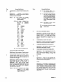
REVISION RECORD
REVISION
A
(l/77)
B
(10/77)
DESCRIPTION
Manual released.
To reflect ITOS 1.1
chan~es.
Publication No,
96769450
REVISION LETTERS I. 0, Q AND X ARE NOT. USED
~ 1977
by Control Data Corporation
Printed in the United States of America
ii
Address comments concerning this
manual to:
Control Data Corporation
Publications and Graphics Division
4455 Eastgate Mall
LaJolla, California 92037
or use Comment Sheet in the back or
this manual.
.4
LIST OF EFFECTIVE PAGES
New features, as well as changes, deletions, and additions to information in this manual, are indicated by bars in the margins o~ by a dot
near the page number if the entire page is affected. A bar by the page number indicates pagination rather than content has changed.
PAGE
Cover
Title page
ii
iii/iv
v/vi
vii
viii
1-1
1-2
2-1 thru 2-3
3-1
3-2
3-3
4-1 thru 4-3
4-4
4-5 thru 4-8
4-9
4-10 thru 4-14
4-15
4-16
5-1 thru 5-14
5-15 thru 5-18
6-1
6-2
6-7
6-8
6-9 thru 6-23
6-24
6-25
6-26
6-27 thru 6-32
Comment
sheet
Mailer
Back cover
96769450 B
REV
PAGE
REV
PAGE
REV
PAGE
REV
PAGE
REV
--B
B
B
B
B
A
A
A
B
A
A
A
B
A
B
A
B
A
A
B
B
B
A
B
A
B
A
A
B
B
-
-
iii/iv
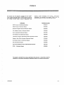
PREFACE
iP
The manual lists the diagnostic messages for the CDC@
Mass Storage Operating System (MSOS) Version 5 and the
major systems operating under it. This manual is directed at
the CYBER 18/1700 MSOS Version 5 programmer and
assumes a basic knowledge of the system. Information
concerning the commands that operate MSOS 5 and the
associated systems is found in the following manuals:
Publication
Publication Number
MSOS Version 5 Installation Handbook
96769410
MSOS Version 5 Reference Manual
96769400
Software Peripheral Drivers Reference Manual
96769390
File :v1anager Version 1 Reference Manual
39520600
Macro Assembler Reference Manual
60361900
MS FORTRAN 3A/B Reference Manual
60362000
1700 Small Computer Maintenance Monitor Reference Manual
39520200
Magnetic Tape Utility Processor Reference Manual
96768400
Sort/Merge Version 1.0 Reference Manual
96769260
RPG II Reference Manual
96769000
Operational Diagnostic System (ODS) Reference Manual
39452100
ITOS 1
96768290
Reference Manual
•
This product is intended for use only as described in this document. Control Data cannot be
responsible for the proper functioning of undescribed features or unidentified parameters.
96769450 B
v/vi
CONTENTS
)
E!WMMijW';
1.
2.
INTRODUCTION
SYSTEM INITIALIZER ERROR CODES
System Initializer
System Initializer
System Initializer
System Initializer
Error Recovery
Codes
Loader Errors
Disk Error Messages
Device Failure Codes
GENERAL SYSTEM ERRORS
Miscellaneous
Loader Error
File Manager
File Manager
4.
General System Errors
Codes
Codes
Request Errors
RECOVERY PROCEDURES
SYSCOP
SCMM
Operator-SCMM Interface Error
Messages
Engineering Log
ODEBUG
Brea.kpoint
Recovery Programs to Save System State
Recovery
5.
JOB PROCESSOR AND UTILITIES
Job Processor Error Codes
SKED
LIBILD
LIBEDT
LIBMAC
COSY
Sorting and Listing
Program Trace
Macro Assembler
MS FORTRAN
FORTRAN Compilation Error Messages
FORTRAN I/O Run-Time Error
Messages
Miscellaneous FORTRAN Error
Messages
Input/Output Utilities
IOUP
SETPV4
DSKT AP /DTLP
MTUP
Action Messages
Descriptive Error Messages
Serious Error Messages
Warning Error Messages
FDDUTY
96769450 B
aee
•
. . .w
1-1
2-1
2-1
2-1
2-2
2-2
2-2
3-1
3-1
3-2
3-2
3-2
4-1
4-1
4-9
4-9
4-14
4-15
4-15
4-16
4-16
5-1
5-1
5-2
5-2
5-3
5-4
5-4
5-5
5-5
5-6
5-7
5-7
5-10
5-11
5-11
5-11
5-12
5-12
5-12
5-12
5-13
5-13
5-14
5-14
..
, ,
'.!ie-
4iHSUM lWN·§·j
Sort/Merge (SMC)
Sort (DSORT)
Text Editor
RPG II
6.
INPUT/OUTPUT STATEMENTS
Basic Equipment Malfunction
Device Failure Codes
Special Messages
1744/274 Digigra.phic Controller
Errors
1745/210 Local Terminal
Controller Errors
1747 Data Set Controller Error
Equipment Status Codes
752 Terminal
1711/1713 Teletypewriter
1721/1722/1777 Paper Tape
Station Reader
1723/1724/1777 Paper Tape
Station Punch
1726-405 Card Reader/Controller
1728-430 Card Reader/Punch
Controller
1729-2 Card Reader
1729-3 Card Reader/Controller
1725-1 Card Punch
1721/601 Magnetic Tape
Controller
1732-1/608/609 Magnetic Tape
Con.troller
1732-2/615-73/615-93 Magnetic
Tape Controller
1733-1/853/854 Disk Drive
Controller
1733-2/856-4 Cartridge Disk
Controller
1738-853/854 Disk Drive
Controller
1739-1 Cartridge Disk Drive
1740-501 and 1742-1 Line
Printer Controller
1742-30/120 Line Printer
1743-2 Asynchronous
Communications Controller
1744/274 Digigraphic Controller
1747 Data Set Controller
1751 Drum Interface and Storage
1752 Drum Controller
1784 Teletypewriter Controller
(1711-4/5, 1713-4/5)
1811 CDT
1827-2 Line Printer
1828-1 Card Reader Controller
and 1829-30/60 Card Reader
1832-4 Magnetic Tape Controller
and 1862-72/92 Tape
Transports
5-1:'i
5-16
5-18
5-18
I
6-1
6-1
6-1
6-7
6-7
6-7
6-7
6-7
6-8
6-8
I
6-8
6-9
6-9
6-10
6-11
6-12
6-12
6-12
6-13
6-13
6-14
6-15
6-17
6-18
6-20
6-20
6-21
6-21
6-22
6-22
6-23
6-23
6-24
6-24
6-24
6-24
vii
I
1832-5 Cassette Tape Driver
and 1861 Magnetic Tape
Transport (Module FS2CAS
Present)
1833-1/2/3 Storage Module Drive
and 1867 Drive Unit
1833-4 Cartridge Disk
1833-5 Flexible Disk Drive and
1865 Disk Drive
1843-1 Communications Line
Adapter
1843-2 Communications Line
Adapter
1860 LCTT/Formatter
I
I
I
361-1 and 361-4 Communications
Adapter (Even Channel)
361-4 Communications Adapter
(Odd Channel)
364-4 Communications
Multiplexer
Pseudo Tape
COSY Driver
Pseudo Disk
Magnetic Tape Simulator
1500 Equipment
1501 High Level Analog Input
1536 Low Level Analog input
1595 Serial I/O Card
6-25
6-26
6-27
6-29
6-29
6-30
6-30
6-30
6-31
6.;31
6-31
6-31
6-31
6-31
6-32
6-32
6-32
6-32
I
TABLES
1-1
viii
Manual Format
1-1
6-1
Status Type Summary
6-27
96769450 B
1
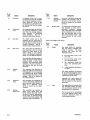
INTRODUCTION
ib6tk,·M4W• •L >tWr"
This manual lists the diagnostic messages that may be
returned to the operator (usually on the comment device) by
Mass. Storage Operating System (MSOS) Version 5 and the
major systems operating under it. The messages are grouped
into five major categories:
o
Ini tializa tion
o
General messages produced by the principal MSOS
programs that refer to malfunctions within the central
processing unit (CPU) or directly associated with file
management
•
Messages from background programs operating under
the job processor (many of these utilities may also be
called by foreground programs)
•
+';,g.'?e.g··i
"
In general, these diagnostic messages are for online operation. Methods for precise hardware diagnosis are described
in the Operational Diagnostic System (ODS) Reference
Manual. Many input/output devices may have several status
words. This manual lists only the principal status word,
which is saved in the physical device table as word 12 and
also is saved in the engineering log following an unrecoverable error. In some cases, a few of these additional status
words are routinely saved in the unit's physical device table
and can be read directly from the proper slot in that table
by a user's program.
For a full description of these
additional status words, the reader should consult the
hardware maintenance manual for the particular equipment
(controller).
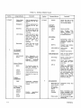
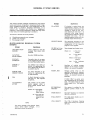
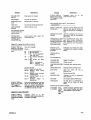
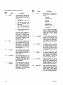
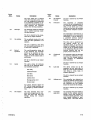
Table 1-1 lists the systems described in the manual.
Messages directly associated with input/output device
failures
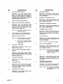
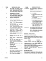
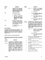
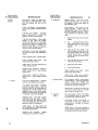
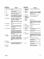
TABLE 1-1. MANUAL FORMAT
Section
Category/System
2
System Initialization
3
Initializer
Initializer
loader
Disk errors
Initializer
device failure
errors
General System
General errors
Loader errors
File manager
errors
96769450 A
Comments
Section
4
To aid the user, these
messages, which come
from operations that
are interleaved, are
labeled as to source initializer loader, disk, or
logical unit.
These errors are from
scheduling, dispatching
functions, etc.
These errors are for reloca table binary loading; same messages are
used whether the foreground or background
program is loaded.
These are the same
error messages whether
file manager is called
from the foreground or
background.
The job
processor and text editor files are treated
separately.
Category/System
Comments
Recovery
Procedures
SYSCOP
messages
SCMM
messages
Engineering
file
System checkout is a
diagnostic program to
analyze the image of
core saved in mass storage at the time of failure. The program executes online at a low
priority level.
Small Computer Maintenance
Monitor
(SCMM) provides online
confidence tests for
error isolation on peripheral devices. It is not
applicable to CYBER
18-20 or 18-30 Timeshare Computer Systems.
This file contains the
status of input/output
devices at the time of
each
unrecoverable
error. Commands allow
the user to view the file
contents online at any
time.
1-1
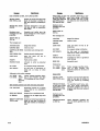
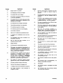
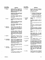
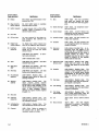
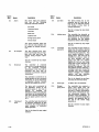
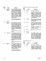
TABLE 1-1. MANUAL FORMAT (Contd)
Section
(4 Contd)
Ca tegory /System
Comments
Online debug
(ODEBUG)
Aids the programmer in
checking out his program
Breakpoint
Aids the programmer in
checking out his program
Recovery
Allows the user to find
the system state at the
end of an online job
execution.
Abort dumps
Snap dump
Section
(5 Contd)
Category/System
TRACE
ASSEM
FTN
Allows the user to save
part of all of the main
memory following an
abort stop. The contents are listed on a
printer
for
visual
checking.
Allows the user to get
the listing of major
registers online
10UP
Input/output utility to
transfer data from one
peripheral device to
another
SETPV4
Magnetic tape installation file utility
Disk-to-tape
data
transfers
Magnetic tape utility
MTUP
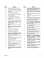
Executive
Data Management
Basic diagnostics for
the background executive; available to all
programs
operating
under the job processor
Allows a wide range of
file manipulations
EDITOR
Allows data manipulation within job processor files
Report
generator;
allows rapid data manipulation within highly
formatted files. Diagnostics are not given in
this manual, since they
are very numerous and
highly specific. Diagnostics are fully described in the RPG II
Reference Manual.
LIBILD
LIBEDT
LIBMAC
RPG II
The skeleton editor defines the contents of
the library to be built.
Builds libraries
Alters existing libraries
Maintains the macro library
Program
Compression
COSY
Compresses programs;
used for program maintenance
Sorting, Listing,
and Tracing
OPSORT
EESORT
LISTR
LULIST
1-2
Provide
specialized
sortings or listings
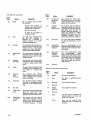
6
Also see File Manager
Codes in section 3.
Sort/merge
Library Utilities
SKED
Macro assembler
Mass storage FORTRAN; includes run
time diagnostics as well
as compiling errors
I/O Utilities
Job Processor
and Utilities
Job Processor
errors
Allows the user to list
status information on
the running program
Languages
(Compilers)
DTLP /DSKTAP
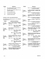
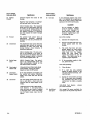
5
Comments
I/O Equipments
Basic logic unit
failed message
Error codes
for logic unit
failure
Designates device that
failed
Special
messages
Some controllers have
failure messages in addition to the basic logic
unit failure message
Status words
Words available in engineering log
96769450 A
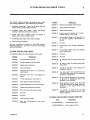
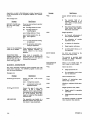
SYSTEM INITIALIZER ERROR CODES
2
hS
This section contains messages encountered when errors
occur during initialization. Five subsections are included:
•
Initializer error codes. These are all errors that are
neither loader nor disk hardware related.
•
Initializer loader error codes.
These are related
directly to problems the loader encounters.
•
System disk error messages. These are related to
address and test data on disk writing.
•
Initializing input/output device failure message
•
Error recovery procedures
The user is referred to section 6 of the MSOS Version 5
Reference Manual for the control comments used during
·system initialization.
Message
ERROR 10
Ordinal name without ordinal number
ERROR 11
Doubly defined entry point
ERROR 12
Invalid ordinal number
ERROR 13
Loader control statement out of orderCorrect order is L, LP, M, MP
ERROR 14
Data declared during an *M load but not
by the first segment; initialization restarted
ERROR 15
Not used
ERROR 16
Irrecoverable mass storage input/output
error
ERROR 17
Irrecoverable loader error; last program
loaded was ignored.
ERROR 18
Not used
ERROR 19
Not used
ERROR 20
*S, ENDOV 4, hhhh not defined before first
*L
ERROR 21
*S, MSIZV 4, hhhh not defined before first
*LP or *MP
SYSTEM INITIALIZER CODES
The following defines the system initializer error codes:
Message
Significance
Significance
ERROR 1
Asterisk initiator missing
ERROR 2
Number appears in the name field
ERROR 3
Illegal control statement
ERROR 4
Input mode illegal
ERROR 22
Attempt to load part 1 core resident into
nonexistent memory
ERROR 5
Statement other than *y or *YM previouslyentered
ERROR
~3
The name used in the second field of an
*M control statement was not previously
defined as an entry point.
ERROR 24
The entry point, SECTOR, was not defined
at the start of initialization and is not
available to the initializer.
ERROR 25
Illegal partition number in the first field
of an *MP statement or illegal number of
partitions in the second field of the
statement.
ERROR 26
An attempt was made to load- an *MP
program when no partitioned core table
exists in SYSDAT.
ERROR 6
Statement other than *y previously entered
ERROR 7
*y not entered prior to the first *L
ERROR 8
Name appears in the number Jield
ERROR 9
Illegal hexadecimal core relocation field
ERROR A
Illegal mass storage sector number
ERROR B
Errol" return from the loader module
ERROR C
Not used
ERROR D
Not used
ERROR E
Field terminator invalid
ERROR F
More than 120 characters in the control
statement
96769450 A
SYSTEM INITIALIZER LOADER ERRORS
Significance
LOADER ERROR 1
Unrecognizable input
LOADER ERROR 2
Mass storage overflow
2-1
Significance
Where:
nn
is the initializer logical unit that has failed.
is the failure code.
LOADER ERROR 3
Out-of-order input block
xx
LOADER ERROR 4
Illegal data or common declaration
yyyy is the last hardware status of the failed
device.
LOADER ERROR 5
Core overflow
LOADER ERROR 6
Overflow of entry point table
RP
To repeat the request
LOADER ERROR 7
Data block overflow
CU
LOADER ERROR 8
Duplicate entry point
Abort the operation and return to the comment device for a subsequent control statement.
LOADER ERROR 9
15/16-bit arithmetic error
LOADER ERROR 10
Unpatched externals
The error reponse is one of the two following entries:
LOADER ERROR 11 Insufficient core
SYSDAT and paging
for
both
ERROR RECOVERY
LOADER ERROR 12 Illegal page number used
LOADER ERROR 13
The initializer handles error recovery and flags error
conditions as they occur.
Most error conditions are
immediately recoverable, but if an irrecoverable loading
error occurs in the loading of a program, the initializer
bypasses the remainder of the program and continues loading
the next program. ERROR 17 appears on the comment
device.
Undefined transfer address
LOADER ERROR 14 Invalid function for loader
LOADER ER.ROR 15
Link table overflow
LOADER ERROR 16
External table overflow
LOADER ERROR 17
Entry point
7FFF l6
absolutized
The .device failure codes for the system or initializer driver
follow. The xx failure codes are defined in section 6. These
failure codes are the same for initializer and normal MSOS
processing.
to
SYSTEM INITIALIZER DISK ERROR
MESSAGES
The following list identifies some of the problems that may
cause initializer malfunctions:
Problem
Initializer stops while
loading the SYSDAT
program
Significance
DISK ERROl"
The address tag write sequence
was attempted, but an internal/external reject was found.
DISK FAILURE xx
Surface test operation caused
error xx. Refer to the device
error codes to interpret xx.
DISK COMPARE
ERROR SECT aaaa
WORD bbbb IS cccc
sa dddd
Surface test pattern error on
sector aaaa at word bbbb. Only
one error is listed per sector.
Data read was cccc but it should
be dddd.
SYSTEM INITIALIZER DEVICE
FAILURE CODES
When the system initializer device detects an input/output
failure, the message is printed:
L, nn FAILED xx (yyyy)
ACTION
2-2
Cause
Index I (location FF 16) is
not assembled in SYSDAT as
a BSS(1). Locations 0 and
FF 16 usually contain the
same value, which is the
address of the initializer's
constant table.
The first *L control statement tried to load SYSDAT
into the system library (an
·Y,PROO,l statement has
been used). The SYSDAT
program establishes the
location of the system
directory and therefore cannot be placed in the directory. This can be avoided by
changing the first *y statement to *Y,PROO,2.
Initializer stops or
restarts during loading
Data has been stored over
the initializer or a previously loaded program link
string by an ORO instruction. Locate the ORO instruction.
96769450 A
Problem
Job processor
function partially
Problem
When certain functions of
the job processor are not
working, it may be a system
problem, or the construction
of the system library may
not correspond to the order
in the *y and *YM statements.
No autoload after
successful initialization
The cause may be an improperly constructed interrupt trap or priority structure or a missing driver.
Initializer terminates
input or output
One of the following:
96769450 A
o
The requested device is
not turned on.
o
The requested device is
not ready and is locally
cleared.
Initializer skips the
next program after an
*y statement
Cause
•
The equipment or station is not properly prepared for the in itializer.
•
A hardware malfunction
exists.
When the *y statement instructs the ini tializer to
read subsequent control
statements from the binary
input device, the record
read may be the NAM block
of the program that cannot
be recognized as a control
statement. Either place a
control statement at the input device before typing *y
or type * instead of *Y.
2-3
GENERAL SYSTEM ERRORS
This section contains messages encountered by the general
system operating in foreground or background mode. Diagnostic messages generated only in the background mode are
found either in section 4, Recovery Procedures, or in
section 5, Job Processor and Utilities (i.e., background,
programs). Input/output diagnostics, though they may occur
in any mode, are treated separately in section 6.
Message
. If a device is marked down, yet
requested by a program, and this
device contains no alternate, this
message is typed on the comment device the first time it is
requested after being downed.
The completion address is alwR.ys
scheduled with error. The requesting program should not continually request downed units.
MI INPUT ERROR
The statement presented to the
manual interrupt processor is unrecognizable, or' the requested
program is not supplied.
MM ERR xx LU=nn
T=hhm m :ss S=ssss
Mass storage input/output error
Miscellaneous general error messages
Loader error messages
File manager errors
MISCELLANEOUS GENERAL SYSTEM
ERRORS
Message
I
Significance
CHECKING FILES ERRORS
Errors detected in the file
manager files check after
autoload.
DATE/TIME
ENTRY ERROR
Re-enter MSOS date/time.
EF STACK
OVERFLOW
Currently there is no space
in the engineering file stack
to record this device failure.
EFSTOR LU
ERROR
An attempt was made to
upda te the engineering file
for a logical unit less than 1
or greater than 99.
EFSTOR MASS
MEMORY ERROR
An error occurred in updating the engineering file
on mass memory.
GIxx
A ghost interrupt on interrupt line xx was reported
by LIN1V4.
L,nn FAILED xx
ACTION
Significance
LU nn DOWN
The section is divided into three portions:
•
•
•
3
The number of the failed
device appears when a
driver cannot recover from
an error
Where: nn is the logical
unit of the
failed device
xx is the code that
indicates the
cause of failure
NOTE
Where: xx
nn
is the error
number
is the logiclil
unit
hhmm is the hours/
minutes
ssss
is the hardware
status
OV
Overflow of volatile storage;
appears on the output comment
device - no recovery is possible.
PARITY, hhhh
Memory parity error at the
specified hexadecimal location;
appears on the output comment
device - no standard recovery is
provided.
If hhhh = DSA? no parity error
was encountered on the memory
scan. The parity fault was most
likely caused by a DSA parity
etTor.
SET PROGRAM
PROTECT
The system is waiting for the
program protect swi tch to be
set.
TIMER REJECT
The timer start-up was rejected
(SPACE or MIPRO).
STALL REJECT
The stall alarm disable was rejected (SPACE).
1781-1 REJECT
The 1781-1 Hardware Floating
Point Unit startup was rejected
(SPACE).
The above message is the general input/
output device failure message.
It is
described in detail in section 6.
96769450 B
3-1
LOADER ERROR CODES
Message
E1
Irrecoverable input/output error; terminates
load
E2
Overflow of entry/external table reservation
on mass storage; terminates load
E3
Illegal or out-of-order input block; terminates
load
E4
Incorrect common or data block storage reservation. Occurs if the largest common storage
declaration is not on the first NAM block to
declare common or data storage or, if protected common or data was being used, the NAM
block declared a reservation longer than protected common or data; terminates load.
E5
Program is longer than area or partitions
allotted to it; terminates load.
E6
Attempt to load information in protected core;
terminates load
E7
Attempt to begin data storage beyond the
assigned block; terminates load
E8
Duplicate entry point
E9
High order bit of a relocatable address is set.
or negative relocation has been encountered
during a part 1 load; terminates load.
E10
Ell
E12
E13
E14
E15
3-2
Significance
Unpatched externals; external name is printed
following the diagnostic. When all unpatched
externals have been printed, the operator may
terminate the job by typing in an *T (ci=) or
continue execution by typing in an * (Cr). '-6ore
resident entry point tables may also 'De linked
by typing in an *E.
The minimum amount or core is not available
for load. At least 195 words plus the length of
the loader must be available; terminates load.
Overflow of command sequence storage reservation on mass storage; terminates load.
Undefined or missing transfer address; this
code is not given if the loading operation is
part of system initialization. It occurs when
the loader does not encounter a name for the
transfer address or the name encountered is
not defined in the loader's table as an entry
point name; loading is terminated.
The loader request operation code word is
illegal; terminates load.
Overflow of loader table used to store relocatable addresses that have been absolutized to
7FFF 16; terminates load.
Message
Significance
E16
Entry point name is not in the loader table;
operator must type in the correct entry point
name.
E17
Informative diagnostic.
Relocatable entry
point has been absolutized to location 7FFF 16'
If any program in the system is testing for an
entry point value of 7FFF 16 to indicate that
this entry point is not present, the test is not
valid.
FILE MANAGER CODES
Error
F.M. ERROR 1
Significance
An irrecoverable mass memory error
occurred while space was being returned to the space pool. This error
may result in invalid space pool
threads and/or file space being lost to
the file manager.
To recover, the user may autoload
and then purge all system files. Then
the files may be reloaded from a user
written backup program as described
in the MSOS file manager reference
manual.
FILE MANAGER REQUEST ERRORS
The file request indicator is a parameter returned to the
requestor at the end of a file manager request. The
following is a list of the file request indicator bits.
Bit
Significance
o
File defined/not defined
1
File locked/not locked
2
File store or short read
3
End-of-file encountered
4
At least one more record exists with the same key
value
5
Record does not exist or has been removed
6
Unused
7
Mass storage error
8
No file space left
9
Attempt to store direct outside file manager's disk
space
10
File combination incorrect
96769450 A
Bit
Significance
•
Bit 5 is set for RTVIDX if the record does not
exist or the request is repeated after the end
of the link is reached.
11
File already defined/not defined as indexed
12
Key length not one for indexed-ordered file
•
Bit 4 is set for STOIDX if the file has not been
defined as linked.
13
Unprotected file request attempt to change a
protected file
•
Bit 2 is set for STOSEQ/STOIDX.
14
File request illegal
•
15
File request rejected; this bit is set whenever:
Bit 1 is set for RELFIL, UNLFIL, STODIR,
LOKFIL (already locked), RTVSEQ, RTVIDX,
RTVIDO, and RTVDIR (attempt to remove
from locked file without the combination).
•
96769450 A
Bit 14, 13, 12, 11, 10, 8, 7, or 0 is set.
3-3
RECOVERY PROCEDURES
4
w
The recovery procedures are special programs to aid the
user in recovering from a system malfunction or stop and to
aid him in checking out programs.
•
Control messages (C): System checkout gives messages
to control the operation of SYSCOP. Control messages
appear on the list device unless operator intervention is
required. In this case, the control message and its
associated input are entered via the comment device.
Control messages always appear, regardless of the
message option selected.
•
Error messages (E): Error messages indicate that an
error condition was detected. Gross error detection
messages, as well as specific error messages, are
included in this message level. Error messages appear
on the list device.
•
Support messages (S): System checkout uses support
messages to support, expand, and present information to
the user.
Support messages supply the user with
organized information that may help in isolating errors.
The section has six major sUbsections:
•
SYSCOP messages.
System Checkout Program
(SYSCOP) diagnoses failures in MSOS by analyzing the
core image of the failed system that was saved on mass
storage.
•
SCMM messages.
pherals.
SCMM tests the input/output peri-
•
Engineering log
•
Online debugging program (ODEBUG)
•
Breakpoint program for checking out new programs
•
Recovery programs to save main or selected mass
memory at the end of a job execution or to save
registers and main memory following an abort condition
Support messages may not always be related to an
error. All support messages appear on the list device.
~
S
Message/Significance
A
REGISTER
Q
SYSCOP
aaaa qqqq iiii
When the system fails, the following steps are used to
bootstrap the failed system onto mass memory, so that
SYSCOP can analyze the CPU state at failure time.
Significance: A printout of the contents of the
registers as saved by the checkout bootstrap
program:
1.
Stop the computer. Do not master clear.
2.
Clear the M, P, Y, and X registers.
Where:
aaaa is the contents of A register
qqqq is the contents of Q register
is the contents of I register
iiii
3.
Set the P register to the address 142 16,
4.
Set the SELECTIVE STOP switch.
ister.
5.
E
aaa IS NOT A bbbb DEVICE
Select the Q reg-
Place the computer in run. The computer stops when
the failed image has been transferred. If Q is zero, go
to step 6; otherwise, an error has occurred - retry the
sequence from step 2.
Significance: This error message appears for
input devices that cannot read or output
devices that cannot write.
aaa is one of:
SBI -
6.
Autoload the system.
7.
After system start-up, request SYSCOP via MIPRO.
SBO -
The system checkout program produces three categories of
messages: control, error, and support. The operator selects
the type of message.
SLO SCO -
NOTE
SCI -
All numbers included in the messages are
given in hexadecimal.
96769450 A
Standard binary input device specified in F9 16
Standard binary output device specified in FA 16
Standard print output device specified in FB 16
Output comment device specified in
FC 16
Input comment device specified in
FD 16
bbbb is either READ or WRITE
4-1
Message/Significance
~
E
~
Message/Significance .
ADDRESS IN aa WAS ffff BUT SHOULD BE
iiii
is
the starting address of a
block of allocatable core
jjjj
is
the length of the block plus
the two preceding control
words (that specify length of
block and starting address).
If the length does not match
the length in a directory
entry, XXXX appears on the
listing.
kkkk is
the thread to next empty
block or next word
iiii
Significance:
LOCORE communication
address error. Appears each time an altered
address is found in LOCORE
Where:
aa
is the address of LOCORE
location containing
a
monitor address
ffff is the value at failure time.
addresses
The list of
checked
for
alteration
includes:
ffff
iiii
~ru are the dump of first five words
Contents
B5 16
FNR
B6
COMPRQ
16
B716
MASKT
B916
REQST
BA
VOLR
16
BB16
VOLA
BC
LUABS
16
BD16
SABS
BE16
CABS
BF 16
NABS
EA 16
DISPxx
F4
MONI
16
F8
IMPROC
16
FE 16
ALLIN
is the value at initialize time
*** ALLOCATABLE CORE ERROR
pppp
E
ALLOCATABLE CORE MAP INDEX START
LNGTH THRD DUMP hhhh iiii jjjj kkkk 1111
mmmm nnnn 0000 pppp EMPY iiii jjjj kkkk 1111
m mm m nnnn 0000 pppp
Significance: Support message. The first two
lines appear only once. Ei ther the third or
fourth line appears for each block of
Only the first system
allocatable core.
directory with matching length appears. If the
block was assigned at failure time, the third
line appears. If the block was not assigned,
the fourth line is printed.
Where:
4-2
hhhh is the ordinal of mass storage
program in the system
whose length matches the
length of the block
BIT TABLE CHECKSUM ERROR
Significance: LOCORE bit table error. An
incorrect checksum of the total of locations 2
through 4616.
At least one location
between 2 and 4616 has been altered. If no
error is detected, the message does not
appear.
E
CONSIDER SW AP RATE TOO RAPID
Significance: System was kept from swapping
because a set time interval had not elapsed.
E
CONSIDER UNPROTECTED I/O HANGUP
Significance: The system is waiting to swap;
unprotected input/output is active.
E
CORE USAGE CAUSED SWAP WHILE JP IN
Significance: The job processor was in core,
and the system was swapped. This is not an
error but occurs normally during job
processing•.
Significance: Error message. Cannot account
for all of allocatable core; a thread is broken.
S
of the block
C
*D
Significance: Output on print logical unit.
This message is valid after SYSCOP announces
DUMP at the end of the program.
DUMP
Significance: The package is waiting for valid
dump addresses. This control message appears
after completing a request or after an invalid
entry. The dump is 16 locations per line unless
the comment logical unit is used. Then, the
dump is eight locations per line (that is, the
list logical unit is the same as the comment
logical unit).
96769450 A
Type
S
iVl essliI?e/Sign ificance
ENTRY FOR LVL hhhh
INITIALLY iiii
CHANGED TO jjjj
INDEX hhhh HAS INVALID REQ PRI iiii
iiii
is the value on autoload image
Significance: Request priority error Inesslll~e.
This message is printed for allocatable cor~
programs. The only program permitted to
have a request priority below 3 is the job
processor. Ordinals for these modules arc
verified and all other programs mw;t be at a
request priority level of 4 or above. This
message appears for each ordinal that does not
have a valid request level.
jjjj
is the value on failed image
Where:
Significance: The image for each level entry
in the modified masl< table
Where:
S
hhhh is the level of
entry - 1 to F
mask table
hhhh is the ordinal in the system
directory
FILEl FILE2 FILE3 FILE4 LOADR BP hhhh iiii
jjjj kkkk llli m mm m
Significance: Support message. These are the
job processor file locations. If an address is
zero, it implies that the respective module was
not active.
Where: hhhh is
iiii
E
the absolute starting addresses of the four files
kkk'1
is
INDEX hhhh TOO LONG FOR REQ PRI iiii
Significance: Error message. This message is
printed for allocatable core program<;. The
only program permitted to have 3 request
priority below 3 is the job processor. Ordinals
for these modules are verified and all othe,'
programs must be at a request priority level of
4 or above. This request priority message
appears for each system directory program
that is longer than the core reserved for its
request priority level.
m~ ~ are the job processing files
1111
the starting address of the
relocatable binary loader (in
TRVEC)
Where:
hhhh is the system directory ordinal
iiii
mmmm is the starting address of the
breakpoint package (F3 )
16
C
S
ILLEGAL BUSY INDICATOR
Significance: Error message. A bit in the busy
word must be set for each permanently busy or
unused partition.
C
IMAGE START SECTOR IS ssss
Significance:
A control message acknowledging the beginning of the image sector
Where:
96769450 A
**. INTERRUPT TRAP
ERROR
E
***INTERRUPT TRAP ERROR INITIALLY
Significance: Header indicates an error message on the autoload image in the interrupt
trap region.
S
INTRPT STACK LEVEL h i j kim no p q r s
t uv w
FORTRAN LEVELS h i j k I (ERROR)
Significance: FORTRAN levels error. There
are errors between the FORTRAN priority
levels 3 and E. h. i. j. k, I are the levels.
E
is the request priority level
Significance: Header indicates an error on the
failed image.
FORTRAN LEVELS h i j k I
Significance:. This support message designates
the legal levels reserved as FORTRAN levels
in FMASK. h. i, j. k. I are the levels.
E
E
FINISH SYSCOP
Significance: Checkout completed; core is
released. This is the last SYSCOP message.
is the request priority level
Significance: This support message gives the
interrupt stack entries:
Where:
h thru ware the levels of the entries
in the interrupt stack; h
is the lowest and should
always be -1; E
is
the highest permissible
level; 16 is the maximum number of entries.
If any of these conditions are violated or levels
are not in ascending order, an error has
occurred. One level can appear only once.
Nothing appears if the stack is empty and the
priority level was -1.
ssss is the starting sector of failed
image
4-3
Type
S
Message/Significance
JP
LOCKED
OUT FOR
UBEDT OR
RECOVERY.
SIGN OFF REQUESTED OF
LIBEDT OR RECOVER Y.
Significance: This support message gives the
job processor lockout switch status. If SWTCH
in TRVEC is negative, only the first sentence
appears. If positive, only the second sentence
appears. This indicates the job processor is
ei ther locked out or the LIBEDT or the
recovery program has requested a sign off. If
SWTCH is 0, the message does not appear.
S
Type
S
LINE 0 1 2 3 4 5 6 7 8 9 ABC D E F
LEVEL h h h h h h h h h h h h h h h h
Significance: This support message gives the
line and level status.
Where:
E
is the· level indicated in the trap
region
LINE 0 IS NOT SETUP FOR PARITY/PROTECT
Significance: This error message indicates
line 0 error. The priority level for line 0
assu med to be F, and the response routine
the internal interrupt handler. When this
not true, this message appears.
JP NOT IN CORE
Significance: This support message indicates
that the job processing executive was not in
core at the time of system failure. Specifically, address pointer FILEl in the TRVEC
program had a pointer of O. No further job
processor checks are made. The job processing
executive maintains four files. These files can
be located from addresses in FILEl, FILE2,
FILE3, and FILE4.
IV! essage/Signi ficance
E
LINE hh IS SET FOR LVL iiii BUT IS ABLE
TO INTERRUPT jjjj
Significance: Mask table error. This error
message appears when no bit is detected in the
mask tables for lower level masks.
hh
Where:
S
the line number
are the priority level numbers; jjjj is lower than
iiii.
E
LAST ENTRY TO BE SCHEDULED hhhh/iiii
jjjj kkkk 1111
Where:
hhhh
is
~mkkkk}
are the dumps of hhhh entry
Where:
the address of a scheduler stack entry
S
LEVEL hh IS USED FOR INTERRUPTS AND
IS RESERVED FOR FORTRAN
Significance:
This error message indicates
that the interrupts cannot use the levels
reserved for FORTRAN.
When FMASK is
unpatched (7FFF), it is assumed no FORTRAN
levels are reserved.
hh
is the priority level number
hh
is
~m}
1111
are the priority level numbers; jjjj is lower than
iiii.
the line number
LINE ii LAST INTERRUPTED tttt
Significance:
Last location interrupted by
each valid line. This support message indicates an interrupt occurred on a line. Line 1
trap is also used by the monitor to initiate or
to resume a program's operations.
llll
Where:
LINE hh IS SET FOR LVL jjjj BUT UNABLE
TO INTERRUPT iiii
Significance: Mask table error. This error
message appears each time a bit is encountered in the mask table for a line at a higher level
than the level indicated in the trap region.
Significance:
This scheduler stack entry
message defines the last entry that was scheduled. If jjjj (starting address) is 0, the message
is suppressed.
E
is
JP WAS IN CORE
Significance: This support message indicates
that FILEl contained a file address.
The
remainder of the job processor checks are
made.
S
a
is
is
is
Where:
E
ii
is the line number
tttt
is the location specified in the
appropriate interrupt trap
LINE ii LAST INTERRUPTED tttt (INVALID)
Significance: The error message indicates an
interrupt on an invalid line. The specified line
4-4
96769450 B
I
Message/Significance
~
has INVINT as its response routine, yet an
interrupt has occurred.
E
Where:
E
ii
is the line number
tttt
is the location specified in the
appropria te trap
Where:
Significance: This error message indicates
unpatched interrupt response routines.
E
ii
is the hexadecimal interrupt
line number that had a
7FFF 16 (unpatched external) for the address of its
interrupt processing routine
S
***LOCORE CONSTANT ERROR
Significance: When the constants contained in
the communication region are checked for
errors, errors are detected on the failed
image. Messages that follow the header refer
to these errors. If no error is detected on the
failed image, the message does not appear.
E
***LOCORE CONSTANT ERROR INITIALLY
LU uu CURRENT PARA LIST AT iiii
RC jjjj
C kkkk
TH llli
LU mmmm
N nnnn
S 0000
I/O IN PROGRESS
Where: uu
iiii
***LOGICAL UNIT CAPABILITY ERROR
Significance: Header message indicating that
the failed image is incorrect. The device does
not have the appropriate read or write
capability.
E
uu} are the logical units whose physvv
ical device table addresses
match in LOGlA, but the
LOGl entry for logical unit
uu does not indicate a
shared device.
Significance: This support message appears
for each busy device. A device is considered
busy if a nonzero logical unit appears in word 5
of the physical device table. The last line of
this support message does not appear if the
diagnostic clock (word 4) is set to minus
(device idle).
Significance: When the constants contained in
the communication region were checked,
errors were detected on the autoload image.
Messages that follow the header refer to these
errors. If no error is found on the autoload
image, this message does not appear.
E
LU uu AND vv MATCH BUT SHARED BIT IS
NOT SET
Significance: This error message indicates
inconsistently shared devices.
LINE ii RESPONSE IS UNPA TCHED
Where:
Message/Significance
jjjj
thru
0000
***LOGICAL UNIT CAPABILITY ERROR
INITIALLY
Significance: The autoload image has logical
units with illegal capabilities (header
message).
is the active logical unit
is the parameter list address
contained in word 6 of the
driver's
physical device
tables; specifies the parameter list upon which the
driver last operated
are the hexadecimal dump of
parameter list at location
iiii
jjjj
is the request code
kkkk
is the completion address
llll
is the thread
mmmm is the logical unit
E
***LOGICAL UNIT TABLE ERROR
nnnn
is the number of words to
transfer
0000
is the starting address
Significance:
Header indicates an error
detected on the failed image.
E
***LOGICAL
INITIALLY
UNIT
TABLE
ERROR
Significance:
Header indicates an error
detected in the logical unit tables of the
autoload image.
96769450 A
E
LU aa IS ALTERNATE FOR uu, BUT HAS
LESS CAPABILITY
Significance: This error message indicates
that the alternate device does not have the
4-5
Message/Significance
read/write capability specified for the primary
device.
E
LU uu IS SHARED BUT UNMATCHED
***MASK TABLE ERROR INITIALLY
Significance: Header message indicates that
an error was detected in the autoload image
mask table.
Where: aa is the assigned alternate logical
unit for logical unit uu
E
Message/Significance
~
S
Significance: This error message indicates
inconsistently shared devices.
MAX CORE WAS hhhh WITH iiii TO jjjj
UN PROT
Significance: Highest core location and bounds
of unprotected core. This support message
indicates no location error was detected. It
appears twice on the printout.
The first
appearance is for the autoload image and the
second for the failed image.
Where: uu is the logical unit in which bit 14 of
the LOGI table entry is set but
for which there is no other logical unit with an identical
physical device table in LOGIA.
Where:
S
LU uu THREAD jjjj kkkk Ull mmmm nnnn
0000 pppp qqqq rrrr •••
Significance:
This support message gives
information about the logical unit threads. It
lists the addresses of the threaded elements
until it encounters an empty entry (FFFF 16).
E
S~gnificance:
Error in core bounds. The error
message indicates that the unprotected bounds
exceed the limits of core, that the top of
unprotected is below the bottom, or that some
of the addresses are negative. It appears
twice on the printout. The first appearance is
for the autoload image, and the second is for
the failed image.
jjjj is the entries on the thread
LU uu THREAD MAY BE BROKEN
S
Significance: If more than 40 16 elements are
on the logical unit thread, only the first 40 16
are listed, and this message appears. It does
not appear for any logical unit whose thread is
empty (that is, FFFF I6)
LU uu WAS MARKED DOWN
Significance: Support message: bit 13 of the
LOGI table refiects an inoperative logical
unit. This message appears for each logical
unit marked down.
Where:
S
E
···MASK TABLE ERROR
Significance: Header message indicates that
the tailed image mask table either contains an
error or was modified.
is the contents of F6 16-1
MAXSEC WAS hhhhhhhh
Significance: MAXSEC value. MAXSEC is in
the LOCORE program. This support message
for the error in MAXSEC appears twice on the
printout. The first appearance is for the
autoload image and the second is for the failed
image.
LU 1 NOT CORE ALLOCATOR
Significance: This error message indicates the
equipment type code if logical unit 1 does not
specify the software core allocator. If logical
unit 1 is the core allocator, the message is
suppressed.
hhhh is the contents of F5 16
iiii is the contents of F7 16 +1
jjjj
Where: uu is the logical unit number
E
is the contents of F6 16-1
MAX CORE WAS hhhh WITH iiii TO jjjj
UNPROT (ERROR)
jjjj
Where: uu is the logical unit whose LOG2
entry is not FFFF 16
S
hhhh is the contents of F5 16
iiii
is the contents of F7 16+1
E
MAXSEC WAS hhhhhhhh (ERROR)
Significance:
Error in MAXSEC.
The
following error message indicates that the
most significant bits specified in MAXSEC
were not zero. This support message appears
twice on the printout. The first appearance is
for the autoload image and the second is for
the failed image.
Where: hhhhhhhh is the most
bits (msb)
significant
96'169450 A
Message/Significance
NO VALID PHYSTB FOR LU uu
Significance: This error message indicates
that the particular LOGlA entry does not
point to a core location that contains a
scheduler request code (52xx16) followed by
three cells, none of which is unpatched. The
message appears for each error.
S
S
PENDING INPUT REQUEST FOR JP
Significance: Manual interrupt handling support message. The MIB flag was set, and
input is for the job processor.
NUM OF LUS DO NOT AGREE, ASSUME hh
S
Significance: This error message indicates
that LOGlA, LOGl, and LOG2 do not contain
the same number of logical units.
The
message does not appear if the first word of
each of the three tables agrees.
E
***POSSIBLE LEVEL HANGUP
Significance: Analysis of system priority level
header. This error message requires further
investigation and appears only if the priority
level is above 2
NUM OF SCHEDL STACK ENTRIES WAS hh
NUM OF SCHEDL CALLS STACKED WAS ii
Significance: Support message:
PENDING INPUT REQUEST FOR MIPRO
Significance: Manual interrupt handling support message. The MIB flag was set, and the
input is for the MIPRO program
Where: hh is the number of logical units as
specified in LOG lA
S
PARTITION THREADS
Significance: This support message appears
with a printout of partition and thread for
every busy partition.
Where: uu is the logical unit number
E
Message/Significance
~
S
PRI LVL WAS hhhh
Significance: This support message gives the
system priority level and is printed only to aid
subsequent debugging.
Where: hh is the total number of scheduler
entries defined in the system
ii is the number of scheduler entries
which were queued when the
system failed
Where:
E
E
Significance: Incorrect priority level. This
error message indicates that the priority level
was not between -1 and 15.
Where:
PARTITION CORE ADDRESSES PARTITION
xx hhhh
Significance: This support message appears
for every assigned partition where xx is the
partition number and hhhh is the starting
address of the partition.
E
C
S
PARTITION IN USE
Significance: This support message appears
when the USE table is analyzed. Each partition in use is printed. Appears with partition
core address message
E
PARTITION OUT OF ORDER
hhhh is the priority level of system
at the time the image was
written on mass storage;;
value is from EF 16.
*R
Significance: Repeat SYSCOP program with
options set. This control message is valid
after SYSCOP announces DUMP at the end of
the program.
PARTITION CORE ERROR
Significance: This header message reports
partition errors.
S
PRI LVL WAS hhhh (ERROR)
PARTITION 0 ABOVE 8000
Significance: Error message: Partition 0 must
begin at 8000 16 or below
S
hhhh is the priority level of system
RETURN FOR FNR WAS hhhh
RETURN FOR CMR WAS iiii
Significance: This support message gives the
last return addresses for FNR and NCMPRQ.
Where:
hhhh is the last location to call find
next request; address should
be in a driver
Significance: Error message: Partitions must
be specified in ascending order.
96769450 A
4-7
Message/Significance
Message/Significance
iiii
E
SBI IS NOT A
is the last location to call
complete request; should be
in a driver
READl DEVICE
{WRITJ
E
C
SELECT OPTION
Type option:
*Z Checkout package released
SBI -
o
Control transferred to dump routine
I
Print error messages only.
2
Print error messages and support messages associated with detected errors.
Print error messages and all support messages.
Significance: This control message indicates
operator selection of the message option.
Each higher option includes the capabilities of
the previous option.
Standard binary input device specified in F9 16
SBO -
Standard binary output - FAl6
SCI -
Input comment - FDl6
SCO -
Output comment - FC 16
3
SLO -
Standard print output - FBl6
.Press RETURN.
SBO IS NOT A
S
SCHEDL STACK ENTRIES hhhh/ iiii jjjj kkkk
lil mmmm/ •••
Significance: Support message:
each entry appears.
When 1. 2. or 3 is completed. the user is again
asked to select options. After a dump is
completed. the typeout DUMP is repeated.
The user may then return to select options.
execute another dump, or release the SYSCOP
program.
This message is repeated if the operator
selectes an undefined option.
A line for
E
Where:
hhhh
are the address of a schedthru
uler stack entry
mmmm
iiii
thru
1111
are the dump of hhhh entry
{~it~}
{~it~}
DEVICE
Significance: See SBI IS NOT A
DEVICE message for significance.
C
***SCHEDULER STACK ERROR
SCI IS NOT A
SLO IS NOT A
READ
{ WRIT
SYSCOP START
Significance: This control message indicates
the start of the checkout program.
Significance: This message indicates levels in
the scheduler stack are inconsistent; priority
level at time of failure is also checked.
E
***SYSTEM DIRECTORY ERROR
Significance: The system directory is not
constructed correctly.
DEVICE
Significance: See SBI IS NOT A
DEVICE message for significance.
4-8
READ
{ WRIT
The first word can be any of the following
devices:
{READ} DEVICE
WRIT
Significance: See preceding message for significance.
E
{READl DEVICE
WRIT J
Significance: See SBI IS NOT A
DEVICE message for significance.
Significance: Standard input/output logical
units read/write capability error. This error
message appears for each input device not
capable of being read or each output device
that cannot write. If all five devices are of
the correct capability. no messages appear.
E
E
SCO IS NOT A
READ
{WRIT
96769450 A
J
S
SCMM
Message/Significance
~
SYSTEM NOT SWAPPED
Significance: This support message appears if
SWAPON is not set but SPASW is set.
The Small Computer Maintenance Monitor (SCMM) provides
a method of online hardware error detection for 1700
Computer Systems. SCMM consists of a main program and
one test program for each input/output device to be tested.
The main program is loaded into the operating system as a
system ordinal and the tests are placed in the program
library. SCMM runs at the lowest foreground priority and all
programs are run-anywhere. This section is intended as a
general description only. For detailed instructions, refer to
the 1700 Small Computer Maintenance Monitor Reference
Manual. SCMM is not applicable on CYBER 18-20 or 18-30
Timeshare Computer Systems.
SYSTEM USING NDISP WITH REENT
FORTRAN (ERROR)
Two types of error indications may be sent to the test
operator:
Significance: This error message appears if
more than one FORTRAN level is reserved in
FMASK, but the system is using NDISP instead
of RDISP.
•
Message for errors occurring during operator-SCMM
interface; i.e., while selecting a list for a particular
equipment.
•
Messages for errors discovered during the hardware
testing. Tests are listed in the following order:
Significance: This support message indicates
that the SW APON flag and the swap waiting
flag (SPASW) were not set. SPASW is in the
TRVEC program.
S
E
S
SYSTEM NOT SWAPPED BUT WAITING TO
SWAP
SYSTEM WAS SW APPED
Significance: This support message appears if
the SW APON flag is set, thus indicating that a
swap is in effect. This flag is in the DRCORE
program.
S
THERE WERE hhhh OF THE iiii VOLATILE
WORDS ASSIGNED
Analog input
. (high and low speed)
Card reader
Digital input/output
(logic level and relay)
Disk
(cartridge, pack, and variable
position)
Drum
Significance: This support message specifies
the amount of volatile storage in use at the
time of system failure is specified by:
I
Where:
hhhh is the amount of volatile storage assigned at failure
iiii
S
is the total volatile storage
available
Significance: This support message gives the
unprotected input/output and timer request
status. If no input/output or timer requests
were active, the message does not appear.
hhhh is the sum of UNPIO
UNPTIM in TRVEC
iiii
C
Line printer
Magnetic tape
Paper tape (reader and punch)
Teletypewriter sample timer
OPERATOR-SCMM INTERFACE
ERROR MESSAGES
hhhh UNPROT REQ WERE ACTIVE AND
STACKED AT LOC iiii
Where:
Events counter
and
is the absolute location of the
stacked requests in the protect processor (PROTEC)
*Z
Message
Significance
CONTROL ERROR
An illegal control statement was
entered by the operator. t
DISK ERROR
A disk error occurred during the
transfer of a test from mass
storage to core. The test may
request parameters, or SCMM
may recycle. If parameters are
requested, the prudent procedure
is to abort the test by typing in ?
and re-requesting the test via
the SCMM monitor.
Significance: Terminate SYSCOP. This control message is valid after SYSCOP announces
DUMP at the end of the program.
t All these entries cause SCMM to display the query line (CONTROL. TEST ID) so the operator can re-enter his request.
96769450 8
4-9
Message
Significance
NOT IN LIBRARY
The test required is not in the
program library. t
PROGRAM NOT
SCHEDULED
PROGRAM
SCHEDULED
Message
CHNLxxxx VALUE
TOO+
Deviation is >+7.
The operator requested a control
statement (STP, PRM, NPT, or
PRT) for a test that had not been
set into execution. t
CHNLxxxx VALUE
TOO-
Deviation is <-7.
Histogram
See SCMM reference manual for
use.
The program requested by the
operator is already in operation. t
LU ERROR
Wrong logical unit
TSTAD2 CHNLxxxx
BAD INDEX
Local index wrong
TSTAD2 CHNLxxxx
EXT REJECT
External reject
TST AD2 CHNLxxxx
INT REJECT
Internal reject
TSTAD2 CHNLxxxx
REJECT
Local reject
TSTAD2 CHNLxxxx
TIME OUT
Time out on channel
The hardware test error messages follow:
Message
Significance
Low speed analog input (1536, 1502-80, 1525-3)
ADR ERROR
Wrong channel shows deviation
value if >+7 or <-7.
CHNLxxxx CK
RELAY VALUE
READxxxx
CHNLxxxx VALUE
TOO+
Deviation is >+7.
CHNLxxxx VALUE
TOO-
Deviation is >-7.
Histogram
See SCMM reference manual for
use.
Card Reader (1726/405)
LU ERROR
Wrong logical unit
TSTAD1 CHNLxxxx
ADC REJECT
Analog/digital
jected transfer
TSTAD1 CHNLxxxx
EXT REJECT
External reject from remote unit
TSTAD1 CHNLxxxx
INT REJECT
Internal reject for remote unit
TSTAD1 CHNLxxxx
MUX REJECT
Multiplexer reject
TSTAD1 CHNLxxxx
TIME OUT
Time out on local or remote unit
controller
CHNLxxxx CK
RELAY VALUE
READyyyy
Each of the following
messages (except the
last) is prefaced by
TST 405 SECxx
CARDSxxxx.
xx is test section number:
1
Wrong channel shows deviation
value if >+7 or <-7.
= read random data
2= read
AAA516'
55AA 16 ,
A555 16 data pattern
4= user supplied data pattern
8 = read sync check data pattern
re-
High speed analog input (1501-x, 1525-3)
ADR ERROR
Significance
ALARM
Output stacker full or card jam
or feed failure
CKSUM ERROR
Holes not clearly punched
EXT REJECT
Device busy or not ready
FEED FAIL
Card did not feed
ILLEGAL ASCII
Punch pattern illegal
INPUT EMPTY
INPUT HOPPER
EMPTY
Both messages indicate no more
cards to read
INT REJECT
Device failed to respond to CPU
within allotted time
NO 7-9 PUNCH
7/9 punch in column 1
FREAD ASCII request
NON-NEG RECORD
LENGTH
Not first card of record
PRE-READ ERROR
Read amplifiers not off during
dark check
READER BUSY
Card in reader
with
t All these entries cause SCMM to display the query line (CONTROL, TEST ID) so the operator can re-enter his request.
4-10
96769450 A
Significance
Message
READER NOT
READY
SEQ ERROR
STACKER FULL/
JAM
TIME OUT
1706 ADDRESS
'ERROR
Busy signal not dropped
Card out of sequence
Stacker full or card jam
No interrupt within allotted time
Buffer address wrong
The following message
occurs without the
usual preface:
TST 405 DATA
ERROR COL xxxx
ACTUAL yyyy
EXPECTED zzzz
Card column xxxx failed the
verification test
Digital I/O, logical level (1553-x/1544-x)
SCMLLV TEST aa
RUN bb 15 cc CHNL
dd STATUS ERROR
eeee
Test error message
Where:
aa
bb
cc
is the test number 1-5
is the run number
is the device identification, e.g., 1533
dd
is the channel identification
eeee is the status for local
10M:
8000 = Bad index or
8001 = Internal
or
external reject
For remote 10M:
7FFF = Reject on local unit
Bit 13 = Receive error (local
control)
Bit 12 = Receive error (remote
con trol input)
Bit 10 = Internal reject on remote unit
Bit 9 = External
reject
on
remote unit
SCMLLV TEST aa
RUN bb OUT CHNL
ffff is gggg IN
CHNL hhhh IS iiii
Data error message where aa and
bb are as shown above, ffff and
hhhh are channel identification,
and gggg and iiii are data format
out and data format on return
Digital I/O, relay (1555/1544)
SCMRLY TESTaa
RUN bb 15 cc CHL
dd STATUS ERROR
eeee
96'169450 A
Message
Significance
SCMRL Y TEST aa
Variables same as
RUN bb OUT CHNL 1553/1544 test above.
ffff IS gggg IN CHNL
hhhh IS iiii
in
the
Disk cartridge type (1739-1, 1733-2/856-2,
1733-2/856-4)
TSTCD1 COMP ERR
TOTAL xxxx
TSTCD1 SEC ADDR
ERROR
Number of errors found after full
block of test data is written to
disk and verified by rereading to
core
Operator attempted to test system area of disk or non-existent
disk tracks
TSTCD1 SEC xx RUN
yy COMP ERR H/W
ADDR zzzz SECTOR
ssss WORD wwww
WAS aaaa IS bbbb
The specified word had a compare error during verification.
SEC specifies the test in progress when the error occurred (6
tests).
Hardware error
messages have this
preamble:
Preamble and trailer have same
meanings as in compare message
above.
TSTCD1 SEC xx
RUNyy
The messages are:
ADDRESS ERR
CHKWRD ERR
CONTROLLER SEEK
ERR
DRIVE SEEK ERR
LOST DATA
PARITY
PROTECT ERR
megal file address
Check on read
Controller seek existing track
Seeking beyond existing track
Data not taken off bus in
allotted time
Parity error on DSA
Attempt to write to protected
main memory
No compare during verification
No disk pack or underspeed, or
heads not on track, or drive
fault.
Followed by this trailer message:
NO COMP
NOT READY
D-C XFER
C-D XFER
H/W
Trailer message specifies direcADDR tion of data transfer and disk/zzzz
CPU address at time of fault
SECTOR
aaaa
Variables same as in the
1553/1544 test above except status 8000 is not legal.
4-11
Message
Significance
Disk (1738/853 and 854, 1733-1/853 and 854)
TSTDKI COMP
ERR TOTAL xxxx
TSTDKI SEC ADDR
ERROR
Hardware error
messages have this
preamble:
Number of errors found after full
block of test data is written to
disk and verified by rereading to
core
Operator attempted to test system area of disk or nonexistent
disk tracks
Preamble and trailer have the
same meanings as in the compare
message above.
TSTDKI SEC xx
RUNyy
The messages are:
ADDRESS ERR
CHKWRD ERR
illegal file address
Check on read
CONTROLLER SEEK Controller seek existing track
ERR
DRIVE SEEK ERR
Seeking beyond existing track
LOST DATA
Data not taken off bus in
allotted time
PARITY
Parity error on DSA
PROTECT ERR
Attempt to write to protected
core
NO COMP
No compare during verification
NOT READY
No disk pack or underspeed, or
heads not on track, or drive
fault.
Followed by this trailer message:
D-C XFER
C-D XFER
H/W
ADDR
zzzz
Trailer message specifies direction of data transfer and disk/
CPU addresses at time of fault.
Message
TSTDVP SEC xx RUN
yy COMP ERR H/W
ADDR zzzz SECTOR
ssss WORD wwww
WAS aaaa IS bbbb
TSTDVP SEC xx
RUNyy
The messages are:
ADR ERR
CHKWRD ERR
DEFTRK
illegal file address
Check on read
LOST DATA
Data not taken off bus in allotted time
No compare during verification
No disk pack or underspeed,
heads not on track, or drive fault
Parity error on DSA
Attempted to write to protected
main memory
Incomplete seek
NO COMP
NOT READY
PARITY
PROTECT ERR
SEEK ERR
Followed by:
D-C XFER H/W
C-D XFER ADDR
zzzz
Trailer message specifies direction of data transfer and
disk/CPU address at the time of
the fault.
Drum (1751)
TSTDMI COMP
ERR TOTAL xxxx
TSTDMI SECTION
xx RUN yyyy COMP
ERR TRACK zzzz
WORD wwww WAS
aaaa IS bbbb
CYL ADR ERR
Requested cylinder is in system
area of disk or is a nonexistent
cylinder.
HEAD NO. ERROR
LU ERROR
Request for a nonexistent head
Request for an illegal logic unit
for disk
Hardware error
messages have the
preamble:
TSTDVP COMP ERR Number of errors found after full
TOTAL xxxx
block of test data is written to
disk and verified by rereading to
core
TSTDMI SECTION
xx RUN yy
4-12
The specified word had a compare error during verification;
SEC specifies the test in progress when the error occurred (six
tests).
Hardware error
messages have this
preamble:
SECTOR
aaaa
Disk variable position test (both 1738 and 1733 Disks)
Significance
Number of errors found after full
block of test data is written to
drum and verified by rereading
to core
The specified word had a compare error during verification.
SECTION specifies the test in
progress when the error occurred
(7 tests).
Where SECTION specifies the
test and RUN specifies the run
number
96769450 A
Significance
Message
The messages are:
CHKWRD ERR
Significance
Message
Line printer (1740/501. 1742-1, 1742-30. 1742-120)
Check on read
GUARDED ADDRESS Attempt to write on protected
ERROR
track
Hardware error
messages have the
following preamble:
LOST DATA
Data not taken off of, or sent to,
DSA within acceptable time
NOT READY
Power not on, speed low, or
temperature or pressure out of
tolerance
The messages are:
POWER FAILURE
Lost ac power to drum
ALARM
PROTECT FAULT
Tried to access protected core
SECTOR OVERRANGE ERROR
Attempted to access nonexistent
track
TIMING TRACK
ERROR
Lost drum timing pulses
Events counter (1547)
TSTPRT SECTION xx Where section number is one of
the six tests in bit configuration
(2,4,8,1°16,2°16,4°16)
Out of paper, torn paper, interlock open, or fuse alarm
EXT REJ
Printer busy or not ready
INT REJ
Device did not reply to CPU in
allotted time
TIME OUT
Device did not generate interrupt in allotted time
Followed by:
DASH NO. ERROR
Choices are 1 and 2
INTERR UPT
ASSIGNMENT
ERROR
Interrupt on wrong line
CNTRL NOT READY Indicates controller status
or CNTRL READY
NO INTERRUPT
Interrupt selected but not generated
Magnetic tape (1731/601, 1732-2/615-73, and 615-93,
1732/608 and /609, 1732/608 and /609, 1706, 1732-3/616-72, 616-92, and 616-95)
Required for testing counting,
interrupts, and events/unit time.
TSTMTT SEC xx
RUN yy TAPE UNIT
zz COMP ERR
RECORD aaaa
WORD bbbb WAS
cccc IS dddd
OUTPUT TYPE
ERROR
1572-1 SYN. NOT
SYSTEM TIMER
Hardware error
messages have the
following preamble:
TSTCTR TEST
RUN yyyy
xx
xx is test 1 or 2; yyyy is run
number
Hardware error
messages have the
following preamble:
The messages are:
TSTMTT SEC xx RUN
yy TAPE UNIT zz
COUNT ERR
The messages are:
NO READ CLEAR
CORRECTED
On reread
DROPOUT (615 only)
READ CLEAR
STATUS ERR
END OF TAPE
Followed by:
ACTUAL aaaa
EXPECTED bbbb
CTRWEMS cccc
Data error on specified run and
unit. Expected and actual words
received are shown. Tests (sections) are 2, 4, 8, and 10 •
16
Where the actual and expected
values are given for the event
counter with WES code cccc
TSTCTR TEST xx
Reject message giving Q, A, and
RUN yyyy CTRWEMS X register values
aaaa INT REJECT
Q = bbbb
EXT REJECT
556 and 800 bits per inch are
ILLEGAL DENSITY
SELECTED (615. 616) legal on seven-track 800, and
1600 bits per inch are legal on
nine-track.
LOST DATA
More data to register before
data transferred
NO ID (615, 616)
Drive not properly addressed
NO WRITE RING
Write command, but tape lacks
write ring
A=cec X=dddd
96169450 A
4-13
Message
NOT READY
Significance
Drive not connected or controller not ready
PARITY
PE LOST DATA (616) Parity errors
PE WARNING (616)
WRONG POSTAMBLE (615)
Postamble not 1 byte of Is fol
lowed by 40 bytes of Os
Message
Significance
Paper tape punch (1713, 1722, 1723, 1778)
The messages are the same as the for paper tape
reader, except the unit identification is TSTPTP and
TAPE SUPPL Y LOW is used instead of MOTION
FAILURE and VALIDATION ERROR is used instead of
CHECKSUM ERROR.
-Followed by:
Teletypewriter (1711-1 through 1711-5, 1713-1 through
1713-5, 1713-10/711 -100/713 -120 1743-2, 1595)
T-C XFER
or
C-T XFER
TSTTTY ALARM
Not ready or lost data
TSTTTY EXT REJ
Teletypewriter replied that it is
not ready.
TSTTTY INT REJ
Teletypewriter did not reply in
the allotted time.
Line break
Parity error
RECORD Indicating the direction of transaaaa
fer at failure time and specifying
the failed record
And, where applicable,
one of these messages:
Short record
TSTMTT SHORT
XFER TSTMTT UNEXPECTED END-DFFILE
TSTMTTTAPE
UNIT xx COMP
ERR TOTALyy
Cumulative error for a single
record check
TSTTTY LINE BK
TSTTTY PARITY
TSTTTY TIME OUT
Teletypewriter did not interrupt
in the allotted time.
ENGINEERI,NG LOG
Paper tape reader (1713,1721,1723,1777)
TSTPTR DATA
ERROR FRAME xx
ACTUAL yyyy
EXPECTED zzzz
Data error on specified frame
word
Error messages have
the following preamble:
TSTPTR SECTION xx Specifying test section (2, 4, 8,
RECS yyyy
or 10 ) and record
16
The messages are:
ALARM
Paper motion fault, lost data, or
no power
BUSY
CHECKSUM ERROR
EXISTANCE CODE
Station does not exist (reader/
punch combination units)
EXTERNAL REJECT Reader replied that it is not
ready.
INTERNAL REJECT
LOST DATA
MOTION FAILURE
NOT READY
PARITY ERROR
POWER FAILURE
4-14
The engineering log stores equipment failure data. Such
data is temporarily stored in a five-entry table in core in the
following format:
Reader did not reply in allotted
time.
87
logical unit
0
1
2
Day - month - year
Military time
3
Seconds
4
Hardware status
1 Error code
Where word 4 is word 12 of PHYSTB for this logic unit.
(This may be a true hardware status or a composite status
formed by the logic unit's controller.)
This information (except the first word) is later stored on
mass memory in sectors so that each sector holds messages
for one logic unit; i.e., 96/4 or 24 failures per device. Each
sector is filled in wrap-around style, which causes the sector
to be a push down/fall off stack.
The error messages are:
Message
MM ERR xx
T =hhmm:ss
LU = yy
S =zzzz
Significance
An automatic message
is sent to the comment
device if a mass storage
error occurs. xx is the
96769450 A
Message
Significance
error code as shown in
section 6; T is the time,
and zzzz is the status
word.
ENGINEERING FILE
INFORMATION LISTING
1. In response to MI, then
LOGICAL UNIT xx
2. In response to MI, then
EFLU:
the failure
codes for the logic units
specified
DATE
aa
name
TIME
hhmm:ss
F AlLURE CODE
bb
EF: all failure codes
for all logic units
3. In response to MI, then
EFMM:
the failure
codes for the core resident mass memory failure table
Message
DB ILLEGAL MM ADD
No such sector address on
mass storage
DB INVALID REQUEST
No such DEBUG mnemonic
for command
DB NO CORE AVAILABLE
Insufficient
ODEBUG
DB ORDINAL LENGTH 0
No program is associated
with this ordinal (identifier)
in the system library.
DB ORDIN AL OVER
MAX
This ordinal is greater than
the largest ordinal assigned
in the system library.
DB SEARCH FINISHED
All searched cells containing
the specified value are listed following the CELL
CONTENT message.
NEXT
ODEBUG is ready for the
next command.
HARDWARE STATUS
cc
Note that the log for each logic unit is a wrap around.
The operator should inspect the date and time to find
the entry for the logic unit most likely to reflect the
particular error he is investigating.
OOEBUG
The on-line debug program (ODEBUG) allows the programmer to access both protected and unprotected main
memory and mass storage. Both kinds of storage may be
searched, altered, dumped, or moved. Main memory may be
allocated; main memory and mass memory may be compared, threads may be traced, and magnetic tape transport
control is available. Commands executed by ODEBUG are
described in the MSOS reference manual.
The messages are:
Message
core
to
load
BREAKPOINT
This background package allows the programmer to check
out a program by use of conditional stops (breakpoints).
When the specified condition occurs and the program stops,
the operator may alter core or registers, dump core as
registers, change the logic units, jump or resume processing,
or dump mass storage. Magnetic tape control commands are
also available.
Commands executed by breakpoint are
described in the MSOS reference manual. The messages are:
Message
Significance
xxxx
FORMAT ERROR
The parameter list field
specified for this breakpoint
command is in error.
I
xxxx
PROTECT ERROR
The breakpoint specified
does not lie wi thin unprotected core.
I
TOO MANY BREAKPOINTS
xxxx
FORMAT ERROR
Only 15 active breakpoints
are allowed; xxxx is the
location of the 16th breakpoint specified in the SET
breakpoints command.
Significance
CELL CONTENT
Shows the cell content in
hexadecimal
DEBUG IN
ODEBUG is ready for the
first command.
DEBUG OUT
ODEBUG has exited from
the system.
DB FORMAT INVALID
The parameter list for the
request is invalid.
DB I/O ERROR
Input/output failure during
processing
DB ILLEGAL LU
No such logic unit in the
LOG tables
Alternate forms of the messages are:
B01, statement
96769450 B
Significance
Statement or parameters
are unintelligible for the
breakpoint program~
4-15
I
Message
Significance
B02, hhhh
The specified hexadecimal
address hhhh cannot be processed by the breakpoint
program because it is protected.
B03, hhhh
The breakpoint limit is exceeded. The specified hexadecimal address is the last
breakpoint processed.
RECOVERY PROGRAMS TO
SAVE SYSTEM STATE
Four programs are included in this group:
•
Recovery, which allows dumps of core or mass memory
following job execution
•
System abort dump, which allows any specified section
of core to be dumped following an abort stop
•
CYBER 18 extended memory abort dump, which allows
any specified section of core within a page file to be
dumped following an abort stop
4-16
•
On-line snap dump, which allows listing of the P, Q, A,
M, and I register contents at any time.
The last three programs have no error messages; failure to
obtain the requested dump is noted by a failure to respond to
commands. The operator should check his request procedure
and repeat the appropriate process as described in the M505
reference manual.
RECOVERY
The recovery package allows the programmer to determine
the state of the system at the end of the job execution.
Recovery requests an operator command. Four standard
commands are available: to dump core, to dump mass
storage, to select an output device, or to terminate
recovery. The program is described in the M505 reference
manual.
There is only one error message:
Message
Significance
INCORRECT OPERATOR
ENTRY
The operator must reenter the proper command and parameter
list.
96769450 A
JOB PROCESSOR AND UTILITIES
The job processor acts as executive for almost all background programs. Included in this section are diagnostic
messages for the following utilities:
•
Job processor entry
•
Skeleton editor (SKED) for building libraries
•
Library builder (LIBILD)
•
Library editor (LIBEDT) for altering libraries
•
Macro library maintenance (LIBMAC)
•
Program compression (COSY)
•
Sorting and listing (OPSORT, EESORT, LISTR, and
LULIST)
•
Program trace (TRACE)
•
Macro assembler (ASSEM)
•
MS FORTRAN (FTN)
•
Input/output utilities
Input/output utility program (lOUP)
Magnetic tape editing (SETPV4)
Disk/tape utility (MTUP).
•
Sort/merge
•
Text editor
•
Report generator (RPG II)
The commands which operate the macro assembler, MS
FORTRAN, magnetic tape utility, sort/merge, and report
generator programs are described each in their own reference manuals. All other programs cited are described in the
MSOS reference manual.
JOB PROCESSOR ERROR CODES
Message
JOB ABORTED
Significance
The current batch job has abnormally
terminated. If the job card included a job
name, that name replaces JOB.
JP,yyyyyy
yyyyyy is the last program the library
program executed before the job terminated.
JP01,hhhh
A program protect violation occurred at
address hhhh.
96769450 A
Message
JP02,hhhh
5
Significance
megal request or parameters at the
specified hexadecimal address, hhhh
JP03, statement An unintelligible control statement is output with the diagnostic.
JP04, statement megal or unintelligible parameters in the
control statement
JP05
The statement entered after manual
interrupt is illegal.
JP06
A threadable request was made at level 1
when no protect processor stack space
was available, or an unprotected threaded
request was made at level 1.
JP07
An unprotected program tried to access
the protected device.
JP08
An attempt was made to access the readonly unit for write or the write-only unit
for read, an attempt was made to access
an unprotected request on a protected
unit, or an attempt was made to select a
mass storage device as the standard print
unit.
JP09
An input/output error occurred while
accessing the job processor file directory
table.
JP10
An operation was attempted on file that is
not in the job processor file table; define
the file.
JPll
The filename being defined already exists
for another job processor file. Dump the
file table to select a name not used
previously or attempt a new definition
with another name.
JP12
An attempt was made to access a job
processor file that has not been opened.
JP13
No job processor files are available for
definition. Purge the file table to make
any expired files available.
JP14
An attempt was made to open a previously
opened job processor file, or an attempt
was made to open more than one file on
the same unit at the same time.
JP15,xxx
The JOB card is not the first control
statement in the job, or more than one job
card is detected within a job. xxx is the
control statement in error.
5-1
SKED
Message
The skeleton editor (SKED) consists of requests to the
installation file builder (LIBILD) that specify the order of
the binary programs that will ultimately become one of the
MSOS libraries.
Message
Significance
COMMAND NAME
NOT UNIQUE
Not enough letters are included to
uniquely define the command.
ERROR IN COMMAND FORMAT
A comma,
omitted.
INVALID CHARACTER IN NUMBER
A nondecimal character is specified
in the number argument.
argument,
etc.,
was
INVALID COMMAND The command is not legal for SKED.
BAD *DEF RECORD.
IDENT CHAR ALREADY
USED. IGNORED.
CHECKSUM ERROR
NOTED IN LAST
PROGRAM
The previously generated checksum does a compare with the
current checksum when the program is read from mass memory.
ILLEGAL CHARACTER
STARTS IDENT FIELD
The identification field
start with a single quote.
ILLEGAL IDENT FIELD.
RECO~D IGNORED.
The *B record was not terminated by a Single quote prior to
colUmn 73.
ILLEGAL *B RECORD.
RECORD IGNORED
The name field of *B must be
enclosed by single quotes.
The device is incompatible with
the function to be performed.
INVALID RECORD
NUMBER
The record number is out of range or
the second argument is less than the
first argument.
INVALID CLASS CODE
LU NOT LEGAL
FOR COMMANDS
The LU type is not valid for the
command requiring the LU.
INVALID DEFINITION
RECORD. IGNORED.
NO INSERTION
RECORD AT
SPECIFIED LU
The device defined for insertion
records does not contain any records.
INVALID LU
RANGE CONTAINS The record that is referenced has
NUMBER ALREADY been deleted.
DELETED
RECORDS HAVE
BEEN PREVIOUSLY
DELETED
The range of record numbers of the
CATALOG command includes numbers that have been deleted.
RECORDS NOT
DELETED PLEASE
RESEQUENCE
SKELETON
An attempt was made to delete more
than 500 records since the file was
last resequenced.
RECORD NUMBER
IS ZERO
The record number of zero is illegal.
SKELETON was not loaded prior to
operating upon it.
LlBILD
The library builder (LIBILD) merges input libraries of
relocatable binary programs into a single output library.
The installation file generated by LIBILD can be used by
LIBEDT or the system initializer to build a system.
Message
Significance
BAD *DEF RECORD. NO *DEF is not the first record of a
definition group.
IDENT CHARACTER
5-2
must
The logical unit is illegal.
INVALID *USE'RECORD. No nonblank character was
IDENT FIELD. RECORD detected prior to column 73.
IGNORED.
INVALID *USE RECORD. The *USE record is infinitely
MAX IMBEDDED LEVEL recursive.
IS 6.
RECORD IGNORED
LAST DECK REJECTED - There are duplicate copies of the
NOT UNIQUE
program; the program identification must be unique.
LAST DECK REJECTED - The binary program does not
NO XFER RECORD
have a transfer record. Type:
1 =Terminate
RESPONSE MUST BE An invalid response to the message:
LU(CR) OR (CR)
ANY MORE INPUT. ENTER LU
SKELETON NOT
LOADED
Significance
2 =Proceed to subsequent library
3 =Continue with current library
MORE THAN ONE
PROGRAM HAS THIS
NAME.
NAME RECORD NOT
1ST RECORD OF DECK
Type:
1 =Terminate
2 = Proceed to subsequent library
3 =Continue with current library
NO DEFINITIONS ARE
STORED. RECORD
IGNORED.
*USE is encountered, but no
definitions are made.
96769450 A
Message
Significance
NO DEFINITIONS WERE
SUCCESSFULLY
LOADED. TOO MANY
DEFINITION SETS.
IGNORED.
Message
Significance
L06
The illegal field in the control statement was
presented to the library editing program, or
and input/output was attempted on a protected
device.
L07
Errors in loading resulted from a library
editing program control statement.
LOS
A program to be added to the program library
has an entry point duplicating one already in
the directory.
LOg
The standard input failed on the first input
record following an *N request.
LIO
The operator is deleting a program that is not
in the library.
Lll
There is no header record on the file input
from mass storage.
Ll2
On an *L entry statement, either there was an
input error or the first record was not a NAM
block.
L13
The common declared by the program being
loaded exceeds the available common, or the
system common was not specified in the
system when requested.
Ll4
The program being loaded is longer than the
size of unprotected core, but not longer than
the distance from the start of unprotected
core to the top of core.
LIS
The illegal input block was encountered; the
last program stored in the library is not
complete.
Ll6
An input/output input error occurred; the last
program stored is not complete.
Ll7
An *L program being installed exceeds the
capacity of LIBEDT to input from mass
storage.
LIS
An attempt was made to load a zero-length
program during an *M request or an *N
request.
Ll9
No data base entry point is specified in the
system for use by an *A statement and
parameters.
L20
An irrecoverable
loading.
L21
An attempt was made to write beyond the
maximum sector number specified for
MAXSEC at initialization.
NULL PROGRAM NAME. The name field consists of two
RECORD IGNORED.
single quotes.
PROGRAM HAVING THIS
ID INFO NOT FOUND
PROGRAM NAME TOO
LONG. RECORD
IGNORED
The name on *B contains more
than six nonblank characters.
PROGRAM SPECIFIED
BY THIS RECORD NOT
FOUND.
The first program on the library
with this name is written to
installation file.
TOO MANY BINARY
DECKS LOADED.
CHANGE LIMIT AND
RECOMPILE.
This library has more programs
than LIBILD can process.
XFR RECORD MISSING
FOR LAST PGM LISTED.
PGM DELETED.
Type:
I =Terminate
2 = Proceed to subsequent li.brary
3 =Continue with current library
LIBEDT
The library editor (LIBEDT) program allows adding, deleting,
or altering programs on the program library, replacing
certain programs, setting request priorities for system
library programs, combining programs for output, and
transferring information between peripheral devices and job
processor files.
Message
Significance
LOI
More than six characters in a parameter name
are presented to the library editing program.
L02
More than six digits in a number are presented
to the library editing program.
L03
An improper system directory ordinal was
presented to the library editing program.
L04·
An invalid control statement was presented to
the library editing program.
LOS
The illegal field delimiter in a control statement was presented to the library editing
program.
96769450 A
error
occurred
during
5-3
Message
LlBMAC
The following error codes are output by the macro library
generator (LIBMAC). The format is:
Action: Reads revisions and lists them
with asterisks in columns 1 through 4 until
it reads a DCK/, MRG/, CPY/, or END/
card.
LIBMAC ERROR nn •••
Where nn is one of the following codes:
Significance/COSY Action
02
Illegal parameters on MRG/control card.
COSY aborts.
03
First card from merge input is not a
DCK/control card.
Meaning
Code
01
No MAC definition card
02
Address modifier on MAC card
03
Label field missing or incorrect
04
Illegal terminator after macro name
04
MRG/ control card within revisions decks.
COSY aborts.
05
More than two characters in a MAC or LOC
definition card
05
Illegal parameters on DEL/, INS/, or
REM! control card.
06
Invalid special character on MAC or LOC card
07
Duplicate parameter names on MAC and/or LOC
card
08
Invalid special character in a parameter string on a
MAC or LOC card
09
Address modifier on LOC card
OA
No terminating apostrophe on macro skeleton
record
OB
Parameter name on macro skeleton record not
previously defined on MAC or LOC card
OC
Internal buffer exceeded; skeleton record too long
00
Macro definitions exceeded limit (currently 320
definitions allowed)
Action: Reads revisions and lists them
with asterisks in columns 1 through 4 until
it reads a OCK/ or END! card.
Action: Reads revisions and lists them
with asterisks in columns 1 through 4 until
it reads the next control card.
06
Action: Reads revisions and lists them
with asterisks in columns 1 through 4 until
it reads the next control card.
07
OE
Two sequence numbers on INS/ control
card.
Action: Reads revIsions and lists them
with asterisks in columns 1 through 4 until
it reads the next control card.
08
Control does not follow DCK! card when
merging revisions.
More Jhan 65K of skeleton file defined
Action: Reads revisions and lists them
with asterisks in columns 1 through 4 until
it reads next control card.
The line printed following the error code is the line in error.
All errors are fatal.
09
First card of source deck not CSY / or
HOL! control card. COSY aborts.
10
Requested deck not on input library.
COSY
This program allows the operator to compress information in
the source decks by replacing three or more blanks on a card
with two special ASCII characters.
Message
Significance/COSY Action
nn ERRORS
This message appears at the end of a
COSY job if errors exist. The number
specified is the decimal count of errors in
the COSY job.
****COSY
Cnn****
01
5-4
Sequence numbers out of order within the
revisions set.
First card of revisions deck is not a DCK/,
MRG/, CPY/, or END/control card.
Action: Reads revisions and lists them
wi th asterisks in columns 1 through 4 until
it reads a DCK! , MRG/, or END! card.
11
Deck names on DCK/ and HOL! cards do
not agree when adding new deck to COSY
library. COSY aborts.
12
Revision card following DCK/ card is not
a control card.
Action: Reads revIsions and lists them
with asterisks in columns 1 through 4 until
it reads a control card.
96769450 A
1
Message
13
14
Significance/COSY Action
DEL/ or INS/ card contains sequence
number beyond the end of the input deck.
Message
Significance/COSY Action
L,lu FAILED ec
COSY driver errors are output by the
alternate device handler. All errors are
catastrophic.
Action: Reads revisions and lists them
with asterisks in columns 1 through 4 until
it reads a DCK/, MRG/, or END/ card.
Action: For protected requests, type CU.
For unprotected requests, type DU.
illegal parameter on DCK/ card
ec = 1
2
First record read was not a CSY /
record.
3
END/ card was not the last card
on COSY input.
Action: Uses a second parameter.
4
No end-of-file on COSY input.
DCK/ card requests both H and C or H
and L on the same unit.
5
A read request was made to a
logical unit assigned to output,
or a write request was made to a
logical unit assigned to input.
6
A motion request was made to a
logical unit assigned to input!
output, and no end-of-deck
marker was encountered.
Action: Reads revisions and lists them
with asterisks in columns 1 through 4 until
it reads a DCK/, MRG/, or END/ card.
15
16
Parameter on DCK/ card twice.
Action: C or L parameter is ignored;
processing continues.
17
DCK/ card requests input from logical
unit previously used for output.
Action: Reads revisions and lists them
with asterisks in columns 1 through 4 until
it reads a DCK/, MRG/, or END/ card.
18
COSY output is requested on unit previously used for Hollerith output or
Hollerith output is requested on unit
previously used for COSY.
Action: illegal output requestJs__cleared;
processing continues.
19
Maximum number of output units is
exceeded.
Action: Output is cleared; processing
continues.
20
21
The DCK/ card requests output on a
logical unit previously used as input.
23
96769450 A
REWIND LUnn
This message may appear at various times
during a COSY job. The specified number
is the decimal logical unit to be rewound.
Action: The operator must enter any
value through the standard input comment
device after rewinding the unit.
SORTING AND LISTING
Four utilities are included in this group:
EESORT processes relocatable binary programs to prepare a
listing of program name, card comments, length, common
size, data size, entries, and externals. There is only one
diagnostic message:
Message
Significance
Action: The output is removed; processing continues.
MEMORY OVERFLOW - NO SORT Not enough core to
process the program
The DCK/ card requests C and L output
on the same unit.
OPSORT operates on 1700 series assembly language operands. There are no diagnostic messages.
Action: The L parameter is ignoredprocessing continues.
'
22
Not assigned.
L~STR lists the name and record length of all programs on a
bmary tape. There are no diagnostic messages.
The CPY / control card is not the first
card of the revisions deck.
LULIST lists the system logical units.
diagnostic messages.
Action: The CPY / control card is listed
with asterisks in the first four columns
and the next control card is read.
PROGRAM TRACE
The CPY / card was not followed by a
CPY / or END/ card. COSY aborts.
There are no
Trace provides the operator with the ability to list certain
information about a running program. The program cannot
trace through protected core (e.g., monitor calls, jumps to
5-5
?ispatcher, or calls to find addresses to table of presets), but
It can recommence at the completion address of a monitor
request.
Significance
Message
**DS
Double defined symbol; a name
in:
The messages are:
Significance
Message
SPECIFY P ARMS (ssss,
1111, eeee, aaaa, qqqq,
iiii, x, y)
Trace has been entered, operator
must specify:
ssss Starting address of trace
1111 Starting address of
traced program
eeee Ending address of trace
aaaa Initial contents of A, Q,
qqqq and I registers
iiii
**EX
x if = L, loop instruction listing
is suppressed
y if =S, subroutine instruction
listing is suppressed
TYPE *C TO CONTINUE, Trace reached a point where it
TYPE *Z TO ABORT
cannot logically continue; *C
returns control to the traced
program.
EXECUTION TIME
DURING THIS PART OF
EXECUTION 1784-1 **
1774 ** 1704 ** 1784-2
wwww xxxx yyyy zzzz
When trace is suspended, the
instruction time (in hexadecimal
count) is given for time spent in
the specified computer.
MACRO ASSEMBLER
The macro assembler transforms source language into 1700
series object language. The OPSORT program is often used
with the macro assembler.
**xxxx**yy**********
******yy**********
ABS BASE ERR
5-6
Significance
The location field of a
machine instruction or an
ALF, NUM, or ADC pseudo
instruction
•
The address field of an EQU,
COM, DATA, EXT, BSS or
BZS pseudo instruction
lllegal expression:
•
No forward referencing of
some symbolic operands
•
No relocation of certain
expression values
•
A violation of relocation
•
lllegal register reference
•
A symbol other than Q, 1, or
B is specified.
INPUT ERROR
An error was returned by the
driver when doing a read.
**LB
The numeric or symbolic label
contains an illegal character.
The label is ignored.
MASS STORAGE
OVERFLOW
There is not enough room for
input image on mass storage.
**MC
Macro call error:
Messages are:
Message
•
•
Illegal parameter list
•
No continuation card where
one was indicated
**MD
Macro definition error
**MO
Overlow of load-and-go area;
affects only X option
**NN
Missing or misplaced NAM statement
Format for pass 3 error messages.
If the L option is
selected, errors in pass 3 precede
the source line on the list output.
If L is not selected, error messages are output on the standard
comment unit.
**OP
Illegal operation code, either:
The assembler was loaded at a
different location from the location where it was absolutized.
**OV
-
Format for pass 1 and 2 error
messages:
xxxx A 4-digit line number.
yy
A 2-character error code
(explained below).
•
megal symbol in operation
code field
•
megal operation code terminator
The numeric constant or operand
value is greater than allowed.
97769450 A
Message
Significance
**pp
There was an error in the previous pass of the compilation
assembly. See the output page
immediately preceding the first
page of the listing for the pass 1
or pass 2 error message.
Where:
megal relocation, either:
**RL
•
Violation of relocation
•
Violation of an instruction
rule that requires the
expression value to be either
absolute or have no forward
referencing of symbolic
operands.
Sequence error; tags instructions
with sequence numbers that are
out of order. This is not fatal
and is not counted in the number
of errors reported at the bottom
of the symbol table.
**SQ
variable
* F'
N co de
*N
F ,code,
A compilation free of diagnostics is syntactically correct. The compilation is also free of
common semantic errors, such as undefined
variables in context that require definition. If
the detected error prevents the code from
being generated in a reasonably accurate
manner, the error is considered fatal and
compilation terminates. When an assumption
is made as to the intended meaning of a
statement, the diagnostic indicates the
assumption. When possible, errors that may
not be fatal (e.g., an A in column 3) are
flagged. A reference to such a label (or the
intended nonexistent label) causes the fatal
error.
96769450 A
is a fatal error
is the number of statements in
error; appears only when
applicable
Compilation error. When errors cannot be
detected until all the specification statements
have been read and initially processed, the
error appears in this format. As the specification statements are processed further, a few
diagnostics can be printed. In these cases, the
variable causing the difficulty is printed. The
diagnostic is printed on the next line without a
statement number reference since it is no
longer available.
Where:
N
is a trivial error; only flagged.
Example:
not separating
array declarators in a
dimension statement
F
is a fatal error
code is the number of statements in
error; appears only when
applicable
FORTRAN COMPILATION ERROR MESSAGES
Significance
F
part is the part of statement in
error; appears only when
applicable
The MS FORTRAN package allows the programmer to write
The
his programs in simple English-like statements.
FORTRAN compiler (one of two versions) and run-time
packages (one of three versions) translate the programs to
1700 series code and execute it either in foreground or
background mode.
Message
is a trivial error; only flagged.
Example:
not separating
array declarators in a
dimension statement
no.
MS FORTRAN
Compilation errors are listed at the end of the source listing
and are indicated within the source listing in the following
format:
N
code is the diagnostic number; see
the following message for
listing of codes
An undefined symbol in an address expression
**UD
no., part
Significance
Message
1
The field is not recognizable (illegal characters in field, such as 8 in octal field).
2
The minimum range limit of a constant is
exceeded.
3
More than six characters in a name
4
The maximum range limit of a constant is
exceeded.
5
The exponent is missing in a constant.
6
The subscripted variable was not previously
dimensioned.
7
The expression in an IF statement does not
have initial parenthesis.
8
Incorrect FORMAT statement
9
Illegal use of the .NOT. operator
5-7
Significance
Message
Significance
35
This line, which begins a statement, has other
than zero or blank in column 6; blank is
assumed.
36
Too many labeled common blocks are declared;
continuation of the last declared block is
assumed.
37
The name in this COMMON statement is either
a formal argument or defined in a previous
COMMON statement. The name is ignored.
38
The name is specified as two different types.
This specification is ignored.
39
This byte is typed as other than an integer, or
it is a formal argument. The byte specification is ignored.
40
This byte was previously specified as a
different type. The previous specification is
retained, and this specification is ignored.
41
The bit specified is not within the bounds of
the 1700 series word size.
10
Illegal operator or operand
11
The subprogram reference is illegal.
12
The labeled END card is illegal.
13
The number of arguments differs in references
to the same subprogram.
,14
The implied DO in the DATA statement either
contains the wrong number of subscripts or the
subscript is out of range.
15
The expression has an illegal termination.
16
Unmatched parentheses in an expression
17
The relational operator is missing.
18
The relational operator was used illegally.
19
An asterisk is assumed.
20
Only one
21
A variable and a subprogram name are interchanged.
42
The least significant bit in this specification is
greater than the most significant bit.
The subprogram name does not appear in an
EXTERNAL statement.
43
The name must be an external function or
subroutine name.
One or more DO loops terminate on an
undefined statement label.
44
The field must be a nonzero positive integer
constant.
45
The array has more than three dimensions.
46
The DATA statement contains too many constants for the space provided.
47
The statement has more than five continuation
cards; excess cards are ignored.
48
An insufficient number of constants is provided in this data statement.
50
The constant is not the same type as the
corresponding data cell.
51
The statement redefines the DO loop parameter
52
The statement type is unrecognizable, or it
follows an executable statement.
53
Not defined
54
The statement label is meaningless; the label
is ignored.
55
The statement label was previously defined;
the current label is ignored.
22
23
** is allowed per parentheses level.
24
Illegal subscript
25
The statement is syntactically incorrect.
26
This array was previously dimensioned in a
DIMENSION, COMMON, or TYPE statement or
previously defined in an EXTERNAL statement. The previous dimensioning or defining is
retained, and the new is ignored.
27
28
5-8
Message
The field must be a variable or array name if
processing a COMMON, DATA, EQUIVALENCE, BYTE, or SIGNED BYTE statement;
an array name if processing a DIMENSION
statement; or an array, variable, or FUNCTION name if processing a type statement.
The logical IF statement contains another
logical IF, DO, DATA, or FORMAT statement.
29
The name must be the name of an array.
30
Must be first statement of program unit
32
A missing comma in this statement is assumed.
34
The illegal character in this statement is
changed to a blank.
96769450 A
Message
Significance
80
Subroutine argument table overflow caused by
a large number of declared parameters and
unique references to these parameters.
81
This formal argument was previously specified
as another formal argument or the subprogram
name.
82
Too many formal arguments caused a compiler
table overflow.
83
The above name is not a variable or an array
element.
84
Two elements of the same array or common
block are assigned to the same storage unit.
85
Blank common and formal arguments may not
be initialized with DATA statements.
87
An array element in a BYTE, SIGNED BYTE,
DATA, or EQUIVALENCE statement either
has the wrong number of subscripts or the
subscript is out of range.
88
Too many EQUIVALENCE names caused a
compiler table overflow.
This field on the STOP card must have an octal
number not greater than 77777. STOP is
assumed.
89
At least two elements must appear in an
EQUIVALENCE statement.
68
The field must be a positive integer.
90
The preceding equivalenced symbols have
overflowed the origin of common.
69
The field must be an integer variable.
91
70
The field must be a statement label.
The DATA statement field is not an integer,
real, double precision, or literal constant.
71
This form of the ASSEM argument cannot
reference elements in COMMON, EXTERNAL
names, or subprogram arguments.
92
Missing terminating asterisk or quote in a
literal string as appropriate.
100
72
This type of statement may not terminate a
DO loop.
73
This statement terminates a DO loop when it
is not the last DO encountered.
Catastrophic table overflow; compilation is
abandoned. If the offending statement is
arithmetic or a logical IF, the statement
should be broken into two or more statements
and the program recompiled.
101
74
This GO TO jumps to itself.
Two PROGRAM, FUNCTION, SUBROUTINE,
or BLOCK DATA statements in one program
unit; the second is ignored.
75
A program consisting of only an END card is
illegal.
103
The relative address argument in the ASSEM
statement requires an asterisk at the end of
the preceding instruction.
110
An overflow of the table used for symbol
references; subsequent references are not
listed by the option S processor.
111
The index used in this subscripted variable is in
conflict with the dimension declaration.
Message
Significance
56
The program name is expected in this field.
57
Too many dimensions caused a table overflow.
58
The symbol table overflowed; compilation
terminates.
59
The statement label may not be zero.
~o
There is no apparent exit from this program.
61
Unclosed DO-implied list
62
An unformatted WRITE must have a list.
63
The name must be an integer variable or
integer constant.
64
The name is not implicitly an integer variable.
65
A RETURN statement may appear only in a
subroutine or function definition. A STOP
statement is assumed.
66
Superflous information in this statement is
ignored.
67
77
Too many unique dummy parameter references
caused a compiler table overflow.
78
The label in a DO statement must reference a
statement following it.
79
The maximum allowable number of nested DOs
was exceeded. The DO loop may be implied in
a DO list.
96769450 A
5-9
Message
Significance
113
The maximum number of macros overflowed;
this macro definition is ignored.
114
This macro was previously defined; the new
definition is ignored.
115
Call to an undefined macro.
116
Embedded macros are illegal.
Message
Significance
Where: xx is the decimal unit number of
a device used improperly
7
I/O RQST
statement no.
xx
A write was attempted on magnetic tape
with no write enable. To continue, press
RETURN.
Where: xx is the decimal unit number of
a device is used improperly.
t
152
Arithmetic table overflow.
8
I/O RQST
statement no.
xx
Where: xx is the decimal unit number of
a device is used improperly.
FORTRAN I/O RUN-TIME ERROR MESSAGES
The following error messages apply only to the FORTRAN
input/output run-time.
Message
1
I/O RQST
statement no.
ffff
Significance/Action/Result
Error in a format statement; illegal character in format statement.
Program
terminates.
Where:
2
I/O RQST
statement no.
ffff
gggg
ffff
is the current decimal
value of the format
statement pointer.
megal character in the input field. .Program terminates.
Where:
ffff
is the current decimal
value of format statement pointer
gggg is the current decimal
value of input field
pointer
3
I/O RQST
statement no.
ffff
gggg
Input data exceeds the limits of the 1700
series word: Exponent >139 10 1. Program
terminates.
Where:
ffff
is the current decimal
value of the format
statement pointer
gggg is the current decimal
value of the input field
pointer
4
I/O RQST
statement no.
xx
5
I/O RQST
statement no.
xx
5-10
Attempt to read on a write unit or write
on a read unit. Program terminates.
Where: xx is the decimal unit number of
a device used improperly.
An attempt was made to use a logical un!t
number greater than 99. Program termInates.
9
I/O RQST
statement no.
xx
Backspace at loadpoint. Program terminates.
10
The end of magnetic tape is sensed. To
continue, press RETURN.
I/O RQST
statement no.
xx
12
I/O RQST
statement no.
ffff
Where: xx is the decimal unit number of
a device is used improperly.
Where: xx is the decimal unit number of
a device is used improperly.
megal formatted input; more elements
are given than are contained in an input
record. Program terminates.
Where:
13
I/O RQST
statement no.
ffff
14
is the current decimal
value of the format
statement pointer
megallist; a list is given but there are no
conversion codes in the format statement.
Program terminates.
Where:
I/O RQST
statement no.
xx
ffff
ffff is the current decimal
value of the format
statement pointer
The file is defined twice; more than one
OPEN request is given for the same file.
Program terminates.
Where: xx is the decimal file number for
a mass storage device
15
I/O RQST
statement no.
xx
The parameter is negative or zero; one ~f
the parameters in an OPEN statement IS
negative or zero. Program terminates.
Where: xx is the decimal file number for
a mass storage device
Read or write request after an end-of-file
has been read without first doing an end of-file check. Program terminates.
96769450 A
Message
Significance/Action/Result
•
16
I/O RQST
statement n'o.
xx
The sector address is too large; the
starting sector address or ending address
exceeds 215 -1. Program terminates.
Magnetic tape editing (SETPV 4) provides the capability
to build and maintain installation files. The MSOS
reference manual describes the SETPV 4 command set.
•
Disk/tape utility (DSKTAP via DTLP). The DSKTAP
program is loaded under the job processor using DTLP.
The program allows saving the disk and tape or loading
(protected as well as unprotected) the disk from tape.
The MSOS reference manual describes the DSKTAP/
DTLP command set.
•
Magnetic tape utility (MTUP) provides a variety of tape
commands including tape-to-tape copying, dumps, initialization, record control, motion, and conversion. The
Magnetic Tape Utility Processor Reference Manual
describes the MTUP command set.
•
Flexible disk utility (FDDUTY) provides a variety of
commands for the flexible disk including initialization,
writing programs onto the diskette from another input!
output device, copying data from one diskette to
another, and verifying data from one diskette to
another. The MSOS reference manual describes the
FDDUTY command set.
Where: xx is the decimal file number for
a maSs storage device
17
I/O RQST
statement no.
xx
The file was not defined; a READ or
WRITE request was given for a file that
was not defined by an OPEN statement.
Program terminates.
Where: xx is the decimal file number for
a mass storage device
18
I/O RQST
statement no.
xx
The logical unit is not a mass storage
device. Program terminates.
19
I/O RQST
statement no.
xx
The record number in the READ or WRITE
request is incorrect. The resulting sector
address is out of the range of the file, or
it is zero program terminates.
Where: xx is the decimal file number for
a mass storage device
Where: xx is the decimal file number for
a mass storage device.
MISCELLANEOUS FORTRAN ERROR
MESSAGES
Message
More than 32,767 cells of object code
have been produced
*UD
Undefined symbol in address field
UNDEFINED SYMS
name name name
Undefined statement
variable names
*80
Scratch mass memory overflow
INPUT ERROR
A request from the comment device
for input has returned, on error.
FORTRAN exits the job.
labels
Message
Significance
END OF TAPE LU
nnnn ACTION?
An end of tape mark is sensed while
writing data on magnetic tape. The
operator must respond with either
$RES, to resume action from the
point of the last interruption, or
$END, to terminate the request.
FILE BACKD FILE
nnnn FILE BACKD
RECS nnnn
The specified unit has been backspaced by nnnn files or records.
FILE SKIPD FILE
nnnn FILE SKIPD
RECS nnnn
The specified unit has been advanced
by nnnn files or records.
FORMAT ERROR
Invalid control statement; re-enter
the statement.
IN/OUT ERROR LU
An error occurred in an input/output
operation on logical unit nne
MISMATCH REC
nn*32768+nnnnn
The indicated data is not the same on
both the records being verified.
and
INPUT jOUTPUT UTILITIES
Five programs are included in this category:
Input/output utility program (IOUP) transfers data from
one input/output device to another, compares data, and
commands motions on input/output devicen.
The
devices serviced are card readers/punches, magnetic
tape transports, paper tape equipment, and line
printers. The MSOS reference manual describes the
10UP command set.
96769450 A
IOUP
Significance
CORE OVFL
o
The diagnostic messages for each of these programs follows.
nn
00 through 03; the quotient
obtained by dividing the
total number of records by
32,768. If nn is 0, only
nnnnn is typed out.
5-11
Message
Significance
nnnnn
MODE DIFFERENT
ON MAG TAPE
0
through 32,767; the
remainder obtained by dividing the total number of
records by 32,768.
One or more records on magnetic
tape contain the same information as
the record being verified against but
of a different mode.
UT FORMAT
INCORRECT
The request is not correctly
formatted; parameters and/or delimiters are incorrect.
UT INVALID
REQUEST
The mnemonic request code is illegal.
DSKTAP/DTLP
The DTLP loader function has no diagnostic messages.
DSKTAP messages are as follows:
Message
Significance
DISK ERROR ssss
Disk failed to respond to input/output
commands; ssss is the device status.
ILLEGAL PARAMETERS SPECIFIED
The equipment code is not in hexadecimal format.
SECTOR xxxx
Verification failed; the disk address is
WORD - WW DOES
given.
NOT COMPARE.
TYPE C TO CONTINUE ORA
CARRIAGE RETURN
TO ABORT
SETPV4
SETPV4 error messages are output on the standard list
device. Errors occur in two phases: statement reading and
statement execution. All errors are fatal; however, some
errors may be delayed fatal (DF), allowing all statements to
be read and diagnosed. All errors occurring in the statement
execution phase are immediately fatal (IF) and cause an exit
to the job processor•.. A flag is set and checked on entry to
phase two (execution) and, if set, the execution is not
initiated. The message format is:
Magnetic tape failed to respond to
input/output commands; ssss is
PHYSTB word 12 status.
TURN OFF
PROTECT SWITCH,
TYPE CARRIAGE
RETURN
The computer protect switch must be
off to run DSKTAP.
MTUP
*****ERROR code
~
TAPE ERROR ssss
Error
1
IF
An *L control statement must be the first
statement.
2
DF
megal or wrong format for the control
statement.
There are four types of MTUP diagnostic messages: action,
descriptive, serious errors, and warning errors.
Action Messages
Message
3
IF
An *E must be the last control statement.
4
IF
Output is attempted with parameters less
than the current position.
5
DF
Control statements are out of order
(issued after an attempt sort).
6
IF
The maximum number of control statements is exceeded (1200 maximum).
*DATA SET NAME:
Significance/Action
Label processing: output volumes
require a data set name if not available from input.
Action: DSN="XXXXX"
*INVALID PARM=
"XXX ••• "
*RETYPE PARM:
The characters within quotes are
invalid and may be corrected.
Action: Enter corrected parameter.
7
DF
The first statement is an *I or an *R
statement and cannot have an asterisk (*)
indicating use of the previous binary.
8
IF
An attempt is made to access a unit after
a file mark has been encountered.
9
IF
An *E statement is encountered before an
*0 statement.
Outputting must take
place if there are any *R, *1, *D, or *S
statements in the set.
10
5-12
IF
Mass storage overflow
*MOUNT,OUTPUT,
SCRATCH:
Action: Type carriage return, which
implies that tape is ready, or type
any other character followed by a
carriage return to terminate the
initialize function.
VOLSER=nnnnnn
Informative tape file just opened with
the specified volume serial number
Action: None
*VOLSER=nnnnnn:
VOL NOT
EXPIRED USE:
Label processing:
output volume
header records are checked against
the system date.
96769450 A
Message
Significance/Action
Action: Carriage return implies do
not use.
U implies use, ignoring
expiration date.
10 ERRORS
*CONTINUE:
Serious Error Messages
Message
****SOOO****
Verify function has located 10 consecutive records that contain errors.
Action.
Type carriage return to
terminate or type one character followed by carriage return to continue.
****S001****
Data buffer linkage has been destroyed. Cause: input/output malfunction, CPU malfunction
Action: Reload utility.
****S003****
A required file is not open, and the
specified
function
cannot
be
executed.
An attempted function is not available in the system. The function is
not invalid; rather, the system was
configured without the requested
module.
Action:
possible.
****S004****
Attempt to write on a file not opened
for write.
•
Input/output error; i.e., parity, read,
or write error, lost data, or alarm.
Blocking has been requested, and specified
block size is smaller than specified record
size.
Use another function, if
****S005****
The volume mounted does not contain
a volume label or the header label
sequence is incorrect; i.e., the wrong
volume of a multiple volume file is
mounted.
Open or close the proper
A parameter is not available in the
system. The parameter is not invalid;
rather, the system was configured
without the requested module.
Action: Use another parameter, if
possible.
A variable size error was detected prior
to write.
Action: Attempt to re-execute the function after closing and reopening all files.
Possible hardware malfunction
A fixed block error was detected prior to
write. The record length is not specified.
Action: Close the file and reopen with
the proper record size or dump file to
locate erroneous records.
The file being opened. or closed is
already in that state.
Action:
file.
Variable length block does not match
actual length read, or variable read length
is greater than specified block size.
Action:
Reopen the file with proper
parameters.
****S006****
*PARM NOT
AVAILABLE
•
Action: Close all files. Open input as
undefined and dump records to locate the
erroneous record. The file cannot be
processed as variable length.
Action: Mount the correct volume
and type a carriage return.
*INVALID OPEN
OR CLOSE
Read end-of-file
Action: Retry the function.
Action: Open the file and re-enter
the function.
*INCORRECT
VOL MOUNT:
•
Significance/ Action
Message
*FUNCTION NOT
AVAILABLE
Attempt to close a file already closed.
Action: Close proper file.
Descriptive Error Messages
FILES{S) NOT OPEN
Available memory has been filled.
Action: Free memory by closing a file.
****S002****
****COOO****
Significance/Action
****S007****
The labeled file sequence number is in
error (file is not opened.)
Action:
reopen.
****S008****
Mount the proper volume and
The labeled file EOF1 trailer label contains invalid information that does not
correspond to header label 1Action: This file· cannot be processed
with standard labels.
96769450 A
5-13
Message
Significance/ Action
Message
****S009****
The labeled file is missing end-of-file
trailer labels.
xxxW002xxx
The end-of-tape is sensed on the output
file (unlabeled).
xxxW003xxx
Action: Close the file with end-of-volume
and reopen after mounting the new tape.
Re-enter the function to complete
processing.
****S011****
A double file mark has been sensed on an
input file. Processing is terminated.
Action: Close the input file and mount
next volume. Re-enter the function to
complete processing.
****S012****
Invalid date.
Action: Re-enter the date function with
the proper date.
****S013****
The labeled volume sequence number is
incorrect (occurs after OPEN file is not
opened).
FDDUTY
The FDDUTY error codes are numeric and are preceded by
one of the three characters below:
(blank)
An incorrect user record
*
The resources of the FDDUTY program and/or
computer are not sufficient to execute.
+
A possible irrecoverable hardware problem
Message
Significance
+0540
More than two bad tracks have been detected
while initializing. Discard the diskette and
retry with another diskette.
+0550
The written track of initialized data was not
read correctly, but the hardware did not
detect an error. Retry and/or request maintenance support.
0610
Illegal sector address; the user attempted to
write (using an *A, *B, or *H request) beyond
the maximum allowable sector address. Move
the program to a lower sector address or place
the program on another diskette.
+0620
A fatal flexible disk drive input/output error
has occurred. Assure that the flexible disk
drive unit is ready (the diskette is inserted and
the door is closed) and that the switches are
set properly (i.e., write enabled, initialize
enabled, and unit reverse). If this has been
done, retry with another diskette and/or
request maintenance support.
Blocking is not specified but the block
size and record size have been specified
differently in OPEN.
+0630
The written data, when read, does not compare
exactly. Retry and/or request maintenance
support.
Action: Open the file with the proper
parameters or continu~ the statement.
0710
The specified logical unit is not a flexible disk
drive.
The file count is specified as zero.
0810
One of the parameters of the last read request
record is illegal. For example, the sector
address may be larger than the maximum
allowable sector address.
The ZERO LENGTH block specified in the
OPEN FILE is not opened.
Action: Reopen, specifying the proper
block length.
****S015****
The block or record length specified is not
a multiple of two. FILE, is not opened.
Action:
Reopen, specifying the even
block and record length. If either the
block or record length is odd, the data
cannot be processed by the system.
Warning Error Messages
Message
xxxWOOOxxx
xxxW001xxx
Significance/Action
Action: Re-enter the function with the
proper parameters or continue the statement.
5-14
The input and output record lengths have
been specified differently for COPY.
Action: Re-enter the function with the
proper parameters or continue the statement.
Action: Mount the proper volume and reopen the file.
****S014****
The record count is specified as zero.
Action: Re-enter the function with the
proper parameters or continue the statement.
Action: The file cannot be processed as
labeled.
****S010****
Significance/ Action
96759450 A
Message
Significance
Message
Significance
0910
One of the hexadecimal parameters of the last
read !'equest record is not a hexadecimal digit.
0130
1010
Illegal diskette format; the format (IBM or
CDC) of a diskette to be read or written does
not agree with the last *F request record (if
there is no *F record, CDC format is
assumed). This error should only occur if a
diskette is inserted to be read or written
without first being initialized by the FDDUTY
program.
Illegal sector address; the computer last sector
address to be written (*C) or compared (*V) is
greater than the maximum allowable sector
address.
0140
Illegal *F request; the specific number of
words/sector and/or sector/track is incorrect.
0210
Illegal record after an *A record; position 1
does not contain an asterisk, or position 2 does
not contain a comma (program name specification) or T (terminate).
*0220
Too many program names specified; more than
20 program names have been specified. To
increase the number of program specification
names, the FDDUTY program needs to be
reconfigured.
0230
Illegal record after program name specifications; the record is neither a relocatable
binary record nor an*T record.
0240
No binary program is entered; an *T record
(terminate) was encountered without any
relocatable binary program being loaded.
0250
Program specification error; one or more
. program specification names have not been
encountered as relocatable binary programs.
0260
Illegal NAM record; the NAM record encountered was not the first record of a relocatable
binary program.
Illegal relocatable binary record; an undefined
or illegal (BZS or EXT) relocatable binary
record has been encountered.
0280
Illegal first record of the relocatable binary
program; the first record of a relocatable
binary program was not a NAM record; instead
it was an ENT, XFR, or RBD record.
0290
No end byte was encountered on the last
relocation byte of an RBD record.
*0299
Program size is too large; the size of the
program being loaded (plus the FDDUTY program) is too large to fit in the program
memory area. To load such a program, the
operating system must be rebuilt to sufficiently increase the program memory area.
*0510
+0520
Not enough memory to initialize; the area
needed to properly initialize a diskette (plus
the FDDUTY program) is too large to fit in the
program memory area.
To initialize, the
operating system must be rebuilt to sufficiently increase the program memory area.
Fatal flexible disk drive error while initializing; a fatal error has occurred on the flexible
disk drive. Ensure that the flexible disk drive
unit is ready (diskette is inserted and the door
is closed), and the switches are set properly
(i.e., write enabled, initialize enabled, and unit
reverse). If this has been done, retry with
another diskette and/or request maintenance
support.
Sort/Merge for MSOS 5 is an interactive dialog program. For
several of the diagnostics, the operator has the option of
continuing, avoiding this error, or avoiding this type of
error. The interactive dialog is described in the Sort/M.erge
reference manual.
Significance
Message
ABNORMAL
ERROR = n
Values of n are given below.
operator action is expected.
Track zero was detected to be bad while
initializing. Discard the diskette and retry
with another diskette and/or request maintenance support.
0110
Illegal control record; position 1 of the request
record does not contain an asterisk, or
position 2 does not contain a legal character
(A, B, C, F, H, I, R, S, V, or Z).
0120
Illegal start or end address; the ending sector
address is less than the starting sector address
on an *C or *V record.
96769450 B
No
I
1 = Unexpected release file status
return
2 = Unexpected retrieve
status return
3
+0530
I
SORT MERGE (SMC)
=Unexpected
store
sequence
sequence
status return
4 =Illegal logic unit for work file;
fatal error
5 = Unexpected call to or status
from define file (DEFFIL); fatal
error
6 = Input to binary/decimal conversion was >9999; fatal error
5-15
I
Message
Significance
Message
7 = Fixed tables contain the incorrect edit phase (SMCEDT) size;
fatal error
SEQ DIR ERROR
Sort-only run. Sequence directory
read/write error; run aborted. No
operator action.
8 = Fixed tables contain the incorrect sort phase (SMCSRT) size;
fatal error
SEQUENCE ERROR
Latest record should have preceded
previous record in key merging.
Action:
Operator may direct the
program to delete the record or to
continue with or without operator
interaction for this type of error.
9 = Call to intermediate merge
(SMCIMG) unjustified, since all
remaining strings can be merged
by the final merge (SMCFMG);
fatal error
I
FWRITE STATUS
<parameters>
=
I
INTERPHASE
RECORD COUNTS
DISAGREE
I
OVERSIZE BLOCK
<parameters>
I
RELFIL REQIND =
<parameters>
I
TOO LITTLE CORE
The requested inputs cannot be
No
processed in available core.
operator action.
I
TOO LITTLE DISK
Sort-only run. Inadequate disk space;
run aborted. No operator action.
I
12 = Fixed tables contain the incorrect final phase (SMCFMG) size;
fatal error
TYPE-IN ERROR
Error in trying to interpret operator's
command. Action: Operator reenters
proper command statement.
I
Bad user-defined output file status;
run aborted. Action: Operator must
redefine file.
SORT (DSORT)
Information and request for action:
The operator may direct program to
rewrite the file, to abort the run, or
to continue without operator interaction for format write errors.
The number of output records does
not equal the number of input sort
records. No operator action.
Information on operator's choice of
block size. Action: The operator may
direct the program to reread the file,
to delete it, or to continue without
operator interaction for this block
size type error.
The release file operation failed.
Action:
Operator may direct
program to retry the release or to
continue with or without operation
interaction for this type of error.
I RTVSEQ REQIND = Retrieve error.
<parameters>
I
SEG MENT LIST
ERROR
5-16
I
Store error. Action: operator may
direct the program to again store the
file, to abort the run, or to continue
without operator interaction for this
type of store error.
11 = The call to the final merge
(SMCFMG) unjustified, since the
number of strings to be merged
exceeds the number that can be
merged in a single pass.
DEFFIL REQIND =
<parameters>
I
STOSEQ REQIND =
<parameters>
10 = Fixed tables contain the incorrect
intermediate
phase
(SMCIMG) size; fatal error
I
Significance
Action:
The
operator may direct the program to
again retrieve the file, to delete it,
or to continue without operator
interaction for this type of retrieval
error.
Sort-only run. Work file accountability lost; run aborted. No operator
action
The sorting operation for ITOS (DSORT) is called only from a
procedure. Most errors reported by diagnostic errors lead to
a fatal error. The operator must then alter the procedure
stream. and recenter it. The DSORT utility is described in
the ITOS Reference Manual.
Message
ABNORMAL
ERROR =n
Significance
Values of n are:
1 = Unexpected release file status
return
2 = Unexpected retrieve
status return
sequence
3 = Unexpected
status return
sequence
store
4 = Open file error
5 = Unexpected call to or status
from define file (CREATE)
6 = Input
to
binary/decimal
conversion was >9999
7 = Fixed
tables
contain
the
incorrect edit phase (SMCEDT)
size
8 = Fixed
tables
contain
the
incorrect sort phase (SMCSRT)
size
96769450 B
9 = Call to intermediate merge
(SMCIMG) unjustified since all
remaining strings can be merged
by final merge (SMCFMG)
GETFCB REQIND =
$xxxx
Status word for GETFCB operation
which failed
GETS REQIND =
$xxxx
Status word for GETS operation when
GETS failed
INTERPHASE
RECORD COUNTS
DISAGREE
Number of output records does not
equal number of input sort records
INPUT FILE
LENGTHS ARE
NOT EQUAL
Cannot sort files with unequal record
length
KEY FIELD
EXTENDS BEYOND
END OF RECORD
Key specified is too long for record
OPENFL REQIND =
$xxxx
Status word for OPENFL oper.qtion
when OPENFL failed
14 = Error encountered while trying
to update FCB request
OUTPUT FILE
RECORD LENGTH
IS ZERO
Data sort with all of record used for
keys
15 = Error
encountered
while
processing GETFCB request
OUTPUT RECORD
COUNT BAD
Improper number of records in output
file
PASSED = (number)
The specified number of records were
either processed or skipped
PUTS REQIND =
$xxxx
Status word for PUTS operation when
PUTS failed
SEQ. DIR. ERROR
Sequence directory
error
START OF KEY
FIELD OUTSIDE
OF RECORD
Key position starts before or after
record
TOO LITTLE CORE
Requested inputs cannot be processed
in amount of core space available
TOO LITTLE DISK
Inadequate disk space
operation
TYPE-IN ERROR
Sort
cannot interpret command
statement in the procedure stream
UPDFCB REQIND =
$xxxx
Status word for UPDFCB operation
when UPDFCB failed
VOLUME = (name)
Volume name
10 = Fixed
tables
contain
the
incorrect intermediate phase
(SMCIMG) size
11 = The call to the final merge
(SMCFMG) unjustified. since the
number of strings to be merged
exceeds the number that can be
merged in a single pass
12 = Fixed
tables
contain
the
incorrect final phase (SMCFMG)
size
13 = Error encountered while trying
to close file
aa ••• aa
Numerical data with prefix
aa •.•••• aa
Card image appears with
messages specifying error
other
ABNORMAL
ERROR = (error)
Alerts operator that sorting operation
failed.
ADDROUT SORTS
ONLY 1 FILE
Use only one
ADDROUT sort
BLKSIZ/RECLTH
•NE.l.2.3 ••••
Record length parameter is not
divisor of block size parameter •
CANNOT OPEN
INPUT FILE
Cannot sort the requested file since
it cannot be opened to be read.
input
file
for
or
wri tc
an
a
CLOSEFL REQIND = Status word for CLOSEFL operation
$xxxx
when CLOSEFL failed
CREATE REQIND =
$ xxx x
Status word for CREATE operation
when CREATE failed
DELETE REQIND =
$xxxx
Status word for DELETE operation
when DELETE failed
DONE = (number)
Number of records processed
EXPECTED aa ••• aa
FOUND bb
Sort did not find the type of
parameter expected.
Sorting is
aborted
FATAL ERROR
Sorting operation was aborted
FN=aa ••• aa.bb ••• bb
Reconstructed input file name and
owner
FILNAM=aa ••• aa.
bb••• bb
File name/owner for input or output
files
96769450 B
read
for sorting
VOLUME (name) NOT Volume specified for output file is
MOUNTED
not mounted
5-17
•
TEXT EDITOR
Using its own two files (work file and user file), text editor
can build files or alter any job processor files. The editor
can operate on any file read into its own file sp~ce. The
following diagnostic messages can appear durmg those
commands shown:
Message
Significance/Command
DISK READ ERROR
The work file and scratch file are
kept on disk; each line is read as a
separate record. A disk read or write
error may occur during any read
operation.
Commands: Any
DIRECTORY READ
ERROR
Significance
Message
LINE NUMBER
OVERFLOW
Line number >9999.
RESEQ, the text editor
work file all data up
causing the overflow.
the work file is lost.
For all but
saves in the
to the line
For RESEQ,
Commands: LOAD, MERGE, GET,
AUTO, RESEQ
NAME NOT UNIQUE The operator specified only the first
letter of the command mnemonic
(A,C,D,L, or S). At least the first
two letters of these commands must
be speC!ified.
Commands:
AUTO,
ALIGN,
CHANGE, CLEAR, CONTRL, DE!rTE, DUMr, LIST, LOAD. SAVE.
SEARCW-
The parameter fileid cannot be
obtained while reading the job
processor directory.
Commands: GET, MERGE, SAVE
FILE NOT DEFINED
FILE SPACE FULL
The parameter fileid is not in the job
processor direC!tory.
RPG II
Commands: GET, MERGE, SAVE
Numerous diagnostiC! messages are provided by the report
program generator (RPG II): Compilation errors:
The file manager has run out or spaC!e
to assign to its text editor (work rile
or user file).
•
Control C!ard diagnostics
•
Extention <!Ode diagnostiC!S
Commands:
Any
CLEAR,CONTROL
•
CalC!u1ation diagnostiC!S
•
Output format speC!ification diagnostics
•
Compile time array diagnostics
exC!ept
EXIT,
INVALID COMMAND The necessary charaC!ters at the beginning of the command mnemoniC!
are erroneous, or a necessary parameter is omitted or wrong (e.g.,
k <k )·
2 1
Commands: Any
INVALID LINE
NUMBER
The line number parameter (k or n) is
greater than 9999.
Commands: Any but EXIT, CLEAR,
CONTROL, SAVE, ALIGN
•
5-18
Run time errors
Data manager errors
Disk file utility errors
There are several hundred of these messages that are very
closely tied to the source language format of RPG II. The
messages are listed in detail in the RPG II reference manual,
appendix E.
96769450 B
INPUT/OUTPUT STATEMENTS
Three types of input/output equipment diagnostics are
provided.
•
•
•
The basic failure message (LV xx FAILED yy) that
specifies the unit (xx) that failed and the code (yy) that
specifies the failure cause
DEVICE FAILURE CODES
Device Failure
Code and Error
o
Time-out
Other failure messages produced by a few controllers
(special messages)
1
Lost data
1833-5 Flexible Disk:
pseudo status
CU
To report the error to the requesting program; the
device is allowed to continue processing requests.
CD
To cause any future programs calling the device to
be informed of the failure by their completion
addresses. The error is reported to the calling
program and the device is marked down.
No
subsequent attempt is made to operate this device.
DU
To activate control unit and suspend job processing.
If job processing is not in progress, this action is
not taken and ACTION is retyped. Another option
may be selected.
DD
To activate control unit and suspend job processing.
If job processing is not in progress, this action is
not taken and ACTION is retyped. Another option
may be selected.
96769450 B
bad initiator
Magnetic tape: Use the control unit
option to continue without processing
the lost record or abort the read
option.
nn is the number of the logical unit that failed
xx is the failure code.
To repeat the request
Retype
1829-30/60 Card Reader (diagnostic
logic unit only): bad initiator status
LV,nn FAILED xx
ACTION
RP
Data was not transferred out of the
read register before the next data
word appeared.
1711/1713 Teletypewriter:
the statement.
When a system input/output device driver has detected an
error, the alternate device handler is called. The alternate
device handler prints the following diagnostic message on
the standard comment device if no alternate device is
defined:
Respond to the error by typing one of the following:
Failure to interrupt within the allotted time (requires TIMER package)
The hardware
All other devices:
failed to generate an interrupt within
the allotted time. Hardware maintenance is required.
BASIC EQUIPMENT MALFUNCTION
Where:
I
Significance/ Action
. Teletype:
The operator failed to
supply input within the allotted time.
Ignore the message and continue normally.
Status information. In this manual, only those status
words are described that are readily available to the
user; i.e., the engineering log status (PHYSTB, word 12)
and other status words saved in PHYSTB.
The first and second types of diagnostics are produced for
all input/output devices. For additional information on the
status words, the hardware maintenance manual for the
individual device should be consulted.
6
2
Alarm
Indicates the presence of an abnormal
condition
1713 Paper Tape Reader: paper tape
motion failure. No change in the
feed hold circuit has occurred for 40
milliseconds while trying to read. If
not the end-of-tape, manually position the paper tape so that the end of
the next to last record and the
beginning of the last record are on
opposite sides of the photocells. If
end-of-tape, take the control unit
option.
Paper tape punch: paper tape supply
low or tape break. Abort the punch
operation and correct the problem.
6-1
I
Device Failure
Code and Error
2 Alarm
(contd)
Device Failure
Code and Error
Significance/ Action
Line printer: paper out, paper tear,
fuse alarm, or interlock open. Correct the problem and use the RP
option.
4
Checksum
1729-2 Card Reader: interlock open.
Correct the problem and take the RP
option.
Significance/ Action
FREAD binary:
The sum of the
header word and data in a record did
not balance to zero when added to
the checksum word.
Card readers:
The holes are not
cleanly punched. Check cards for
tears between holes. If the cards are
all right, attempt recovery. Otherwise, perform the following operations:
1728-430 Card Reader:
interlock
open or chip box full. Correct the
problem and take the RP option.
1.
Remove the cards from the input
hopper.
2.
For
1728-430/1729-2/1729-3
only, single cycle the card in the
transport area to the output
stacker.
3.
Take the last two cards in the
output hopper and put them into
the input hopper ahead of the
unread cards; with a multicard
record, re-read all cards within
the record.
bad
4.
For 1726-405 only, press the RELOAD memory switch.
COSY driver: The first record is not
a CSY / control record.
5.
Ready the card reader.
6.
Take the RP option.
1726-405 Card Reader: If the output
stacker is full, clear the output
stacker and type RP. If a card jam
has occurred, abort the operation and
correct the problem. If there is a
failure to feed, attempt to ready the
device and take the RP option.
1829-30/60 Card Reader (diagnostic
for logic unit only): bad continuator
status
1832-5 Cassette Tape: runaway tape
1833-5 Flexible Disk Drive:
continuator pseudo status
Magnetic tape simulator: failure to
fulfill request due to mass storage
device error
1833-5 Flexible Disk Drive:
faults after input/output
Pseudo tape: Failure to fulfill request due to mass storage device
failure.
Parity
1711/1713 Teletypewriter: Attempt
recovery by retyping the command
1713 Paper Tape Reader: Manually
position the paper tape so that the
end of the next to last record and the
beginning of the last record are on
opposite sides of the photo cells.
Repeat the read request by typing RP
in response to the error message.
Magnetic tape: The tape is positioned after the bad record. Either
tape the control unit option to continue processing (the bad record is
ignored) or abort the operation.
COSY driver: The last record was
not an END/record. COSY deck must
have END/record added.
I
status
COSY driver: There was no end-offile mark following the END/record.
5 Internal reject
3
I
The computer cannot communicate
with the device. Check the hardware
address switch and POWER ON
switch. The RP option may be used if
the problem has been corrected.
COSY driver: Read on the write unit
or write on read before the end-ofdeck marker is encountered.
6
External
reject
The input/output device has replied
to the computer that it is not ready
to perform the specified request.
The device is busy or not ready. If
the device is not busy, check the
ready switch. Attempt to continue
by typing RP.
COSY driver: The motion request is
on the read unit after the CSY /record
and before the end-of-deck marker.
Magnetic tape simulator:
illegal
record header or header not found
6-2
96769450 B
Device Failure
Code and Error
7 Compare
Pre-read
Significance
Hardware problem: A compare error
occurs when a faulty signal is detected in the area of the punch
solenoid and echo amplifier circuits
during an echo check.
Device Failure
Code and Error
12 7/9 punch
1728-430 Card Reader: Remove and
discard the last card punched. Ready
the device and type RP.
•
Card readers: Attempt recovery as
for the card checksum error (see
error code 4).
•
A pre-read error occurs if all read
amplifiers are not off during a dark
check.
13 ·Controller
write on
device
The first word of a formatted binary
record is the complement of the
number of records within the record.
The word may be a negative number
indicating that the card read was not
the first card of the record.
Attempt recovery using the procedure for the checksum error (see
error code 4).
11
Read/write
mode change
If mode switch is allowable, repeat
the request using the RP option.
96769450 A
no write ring is
Pseudo tape: An attempt was made
to write on a file that was opened to
read only.
Magnetic tape simulator: An attempt
was made to write with the write ring
not enabled. See manual input operations.
1832-5 Cassette Tape:
enabled
write not
1833-5 Flexible Disk:
The write
enable switch is not set or the diskette has been defined as read only via
a motion request (code = 5).
14 Not ready
Ready the device and use the RP
option.
15 Noise record
1832-4 Magnetic Tape:
A noise
record was detected and ignored.
16 Controller
seek
The controller seek error occurs when
the controller has failed to obtain the
file address selected during a read,
write, compare, or checkword operation. This is usually an indication of
a positioning error.
17
A drive seek error occurs when the
drive unit detects that the cylinder
positioner moved beyond the legal
limits of the device during a load
address, write, read, compare, checkword, check, or write address
function.
Drive seek
Indicates a switch from read or write
mode
1728-430 Card Reader: This message
is issued only as a warning to the
operator.
Magnetic tape:
installed.
Insert the write ring and use the RP
option.
To allow software recovery, the
driver places an ASCII? in the buffer
word for the bad column. Select the
repeat option to continue, or abort
the job and correct the mispunched
cards.
10 Non-negative
record length
If column 1 was misread, read
the card as for a checksum error.
An attempt was made to write on
magnetic tape without the write enabled.
Occurs when the card reader encounters a punch sequence that does
not comply with the Hollerith to
ASCII conversion table being used by
the driver.
Cards within a record are not in
sequential order. Abort the read
operation and restore the sequential
order to the record.
If column 1 is a 7/9 punch, there
is no recovery; the abort operation request is the wrong mode.
Card readers: Attempt recovery as
for· the card checksum error (see
error code 4).
9 Sequence
The error occurs if a 7/9 punch in
column 1 is read when an FREAD·
ASCII request is specified.
Card reader recovery:
1728-430 Card Reader: Remove and
discard the last card punched. Ready
the device and type RP.
8 megal Hollerith punch
Significance
18 Address
This error occurs when an illegal file
address obtained from the computer
is detected or the controller has
6-3
Device Failure
Code and Error
18 Address
(Contd)
Significance
advanced beyond the limits of file
storage.
Device Failure
Code and Error
25 Card jam
Magnetic tape simulator: an attempted read past end of written data
Significance
A card transport problem has occurred. It is possible for a card jam to
occur in anyone or more of four read
stations in the 1728 Card Reader.
CAUTION
1833-5 Flexible Disk: The requested
sector area for input/output does not
fit within the 75 logical tracks that
can be addressed, or initialization of
the diskette attempts to reference
the track beyond the valid 0 through
76 tracks.
19
20
Protect
Checkword
Do not attempt to singlecycle the machine. Damage
to the card transport or
punch head may result. Call
customer engineering to aid
in clearing the jam.
The protect fault occurs when an
unprotected controller operation
attempts to write in a protected core
location.
Jam while reading:
The check word error occurs when the
controller logic detects an incorrect
checkword in data read from file
storage during a read, compare, or
check word operation.
1.
Examine the transport area.
2.
Remove all cards that have completely passed under the read
station.
3.
The cards that have not completely passed the read station
have not been read. Put these
cards back into the hopper.
Ready the card reader and
repeat the request via the RP
option. The cards must be recycled in proper sequence.
4.
If the procedure results in fail-
1833-5 Flexible Disk: The data written to the diskette is not same as
data read from the diskette when the
software compare option is selected
via a motion request (code = 3)~
21
22
23
24
End-of-tape
error
Card output
stacker full
Card input
hopper empty
Card feed
1832-5 Cassette Tape: The end-oftape is an unrecoverable error; the
tape automatically rewinds on the
next back motion command.
Jam while punching:
1728-430/1729-2/1729-3/1829-30/60
Card Readers: Empty the output
hopper and take the RP option.
1.
Clear the jam.
2.
If a card has only partially
passed the punch station, it has
not been punched correctly. Discard the card.
If the read operation is complete, use
the control unit option; otherwise,
supply more cards and take the RP
option.
3.
The read ready station does not contain a card after a f~ed cycle has
occurred and the input hopper is not
empty.
1728-430/1729-2/1729-3/1829-30/60
Card Readers: A card feed failure
error can occur as a result of warped
or damaged cards. If the card reader
can be made ready, take the RP
option.
6-4
ure, abort the read.
Ready the card reader and type
RP. If any cards were damaged,
the operation may have to be
started over to obtain a readable
deck.
1829-30/60 Card Reader:
jam status returned
26 Insufficient
file space
stacker
Not enough file space available for
this request to the pseudo tape driver
96769450 A
Device Failure
Code and Error
Significance
27
Device message
Illegal device message on 1720 Card
Punch
28
File
No file assigned to this logical unit
(pseudo tape driver)
29
Read
A read error occurred in reading the
resident mass-storage driver.
30
Validation
error
The frame punched does not compare
with the original data, or there was
an echo error on the 1720-1 Card
Punch. Abort the punch operation.
31
Short record
An attempt was made to write a
record with a length less than the
standard noise record length.
Device Failure
Code and Error
40
Repea ted the
request due to
an error
The driver is attempting recovery.
41
Incomplete
request
The request was not successfully
completed. The driver attempted to
repeat the request the maximum
number of times.
42
Timing error
Occurred while drum was busy
43
Incomplete
directory call
or overlay read
request
Due to irrecoverable error
44
Guarded
address
Error on write
Magnetic tape simulator: An attempt
was made to write past the end of the
specified magnetic tape simulator
disk area.
Magnetic tape simulator:
noise
record. Attempt to do a zero length
write.
32
33
34
Tape supply
Line break
Data interrupt
Tape supply low on the 1720-1 Card
Punch
45
Timing
Occurred while drum was not busy
A line break occurred while attempting to input on the 361-1 Communications Adapter.
46
External reject
On output
47
External reject
On input
A data interrupt occurred after reading 80 columns.
48
Controller
address
The controller address status was not
the expected value.
1728-430/1729-2/1729-3/1829-30/60
Card Readers: This error indicates a
hardware failure, possibly due to improper card travel. Reread the card
(see the recovery procedure for error
code above).
49
Drive address
The drive address status was not the
expected value.
50
No ID
ID abort, no ID burst (1732-2, 1732-3)
51
Illegal density
An attempt was made to select an
illegal density (1732-2, 1732-3) or an
attempt was made to select a density
when the. unit was not at the load
point.
52
Power failure
Power failure on 1752 Drum
53
EOP
End-of-operation not set after interrupt (1752 Drum)
'--
35
End-ofoperation
An
end-of-operation
interrupt
occurred prior to reading 80 columns.
1728-430/1729-2/1729-3/1829-30/60
Card Readers: Continuous failures
may indicate card slippage in feeding.
Reread the card as for error code 4
above •.
36
Reserved
37
Wrong address
38
Not used
39
Not used
96769450 A
Significance
1829-30/60 Card Reader: no end-ofoperation status
The buffered data channel is using
the first word address other than the
address sent by a buffered driver.
54
Data
The data was not set after the interrupt (1752 Drum).
1829-30/60 Card Reader:
before end-of-operation.
no data
6-5
Device Failure
Code and Error
Device Failure
Code and Error
Significance
55
Status
Bad status (an indeterminate error
occurred on 1752)
56
Mass memory
buffer expired
No more buffer space is available
(software buffer driver).
57
Buffer transfer
A mass memory error on the buffer
transfer, which is detected in the
software buffer driver.
58
Not used
59
PE lost data
An error occurred in the phase encode formatter that affected the
data transfer.
60
megaltape
motion request
An illegal tape motion request was
made to the magnetic tape simulator.
61
Interrupt
status bit
1833-5 Flexible Disk: The interrupt
should not be set when the initial
status is taken.
1829-30/60 Card Reader:
rupt status indication
71
ECC
1833-1 Disk: The error correction
code could not correct the error,
since too many error bits were generated.
72
Ghost interrupt
1833-1 Disk: An unexpected interrupt was received.
73
Force release
1833-1 Disk: A force release was
required but the disk was not released
(multiple disk adapter system).
74 Transfer length
1833-1 Disk: The data transfer was
longer than requested.
75 Transfer
1833-1 Disk: The data transfer was
not accomplished after the maximum
number of retries.
76
Recovery
indicator
1833-5/1865-1 Flexible Disk: An informative error was logged in the
engineering file to indicate recovery
has been performed on this device a
specific number of times.
The
threshold value for the error is contained in word 43 of the physical
device table for this unit.
77
Expected reject
did not occur
1833-5/1865-1 Flexible Disk (diagnostic logic unit only): An illegal
function was issued but did not cause
a reject.
no inter-
1833-5 Flexible Disk: same
62
ADT
1829-30/60 Card Reader:
transfer fault status
B.uto-data
63
Busy after
EOP
1829-30/60 Card Reader: still busy
after end-of-operation occurs
64
Not busy
1829-30/60 Card Reader: not busy
before end-of-operation occurs
65
No interrupt
selected
1833-5/1865-1 Flexible Disk:
no
interrupt select status bit when the
interrupt occurred
66
Memory
address
1833-5/1865-1 Flexible Disk:
The
direct memory access memory
address fault or A/Q transfer attempted to cross a bank boundary or the
direct memory access attempted to
cross a bank boun~ary without
priming the request (motion request
of code =1).
67
Not used
68
Interrupt
status bit
1833-5/1865-1 Flexible Disk:
The
interrupt status bit was not set when
the interrupt occurred.
69
Initialization
not enabled
1833-5/1865-1 Flexible Disk:
The
disk initialization switch was not set.
70
Connect
1833-1 Disk: failure to connect to
the control unit or drive after a
maximum number of retries.
6-6
Significance
78 Transfer
1833-5/1865-1 Flexible Disk:
The
number of words transferred was not
correct or the spindle speed during
initialization of the disk was more
than 3.5 percent off the normal
value.
79
Unit busy
1833-5/1865-1 Flexible Disk:
The
unit is busy at the time the input/output request is attempted.
80
Unit seeking
1833-5/1865-1 Flexible Disk:
The
unit is seeking when the input/output
request is attempted.
81
Unit doing
input/output
1833-5/1865-1 Flexible Disk:
The
unit is doing input/output when the
input/output request is attempted.
82
CU
1833-1 Disk: error in 1833-3 Control
Unit
83
Main memory
1833-1 Disk:
The disk adapter
attempted to address a nonexistent
central processing unit memory
address.
96769450 A
SPECIAL MESSAGES
Error Code
The control units for the 1744, 1745, and 1747 equipments
produce the following error messages. Error messages are
on the comment device unless otherwise specified.
Significance
A
Zero length request; not completed with
error and not executed
B
Software
cannot
(treated as ghost).
identify
interrupt
1744/274 Digigraphic Controller Errors
The comment device error messages are:
Message
Significance
BDC NOT READY
Buffered data channel not ready
BDC BUSY
Buffered data channel busy
DGC NOT READY
Digigraphic console not ready
DGC EXT REJ
Digigraphic external reject
EGC INT REJ
Digigraphic internal reject
Message
Significance
GI1706
Ghost (unexpected) interrupt on 1706 connected to the local terminal controller
GICRT
Ghost interrupt from local terminal controller
1747 Data Set Controller Errors
Message
Significance
1745/210 Local Terminal Controller Errors
DSC REJECT
Data set controller reject
Local terminal controller error messages have the following
format:
BDC NOT READY
Buffered data channel not ready
BDC BUSY
Buffered data channel busy
DSC NOT READY
Data set controller not ready
DSC BUSY
Data set controller busy
TEST MODE
Data set controller in test mode
NO CARRIER
No carrier signal on the data set
CRT yx
Where:
y is the station number of the unit on which the
error occurs.
x is the error code.
Error codes for the local terminal controller are as follows:
Significance
Error Code
o
EQU IPMENT STATUS CODES
Diagnostic timeout
The following status codes appear in one or more of the
following locations:
Reject in initiator
2
Reject doing function output
3
Reject attempting buffered input/output
4
Reject on write terminate function
5
Reject in
interrupt)
6
Reject in interrupt response (end-ofoperation interrupt)
7
Reject in send portion of continuator
8
Reject after end-of-operation in continuator
9
Allocatable core is not sufficient for this
format read size
96769450 A
interrupt
response
(station
•
System initializer error message
•
Engineering log printout
•
PHYSTB for the device (ESTAT2 = word 12)
In this manual, only one status is given; it is the one found in
the engineering log for that device (see Engineering Log in
section 4, for the method of finding the status word). This
status may be a composite status word developed by the
device driver.
In some cases (e.g., the 1833-1 Disk),
numerous status words can be obtained from the device by
use of a WES code requesting status with a director bit set
to the code for the status word desired. See the devices'
hardware maintenance manuals for information on these
status words, some of which may also be saved in other
words of PHYSTB.
6-7
In most cases, the word given may be obtained by a status
request (WES code) to the device. In this case, the status
word is returned in the A register. However, when the
device has multiple status words (see the device hardware
maintenance manua!), the status word shown here is the
status word with the appropriate director code. If the driver
generates a composite status word for ESTAT2, no status
request loads the word given here into the A register.
I
Conlole Driver (752 Terminal)
Status
Bits
Status
4=1
End-ofoperation
The clutch in the teletypewriter
is disengaged.
A change of
controller mode may be accomplished at this time. This status
is equivalent to a not busy
status.
5=1
Alarm
The ready status is a 0, or the
lost data status is a 1. The
alarm status drops when the condition it caused is corrected or
when the interrupt request is
Cleared.
6=1
Lost data
The holding register contained
data for transfer to the computer, and the teletypewri ter
began to send a new character
sequence. Lost data status may
be cleared by a clear controller
function or a select write mode
function after the teletypewriter
is stopped and the character in
the holding register is read or
when the interrupt request is
cleared.
7
Not used
8
Not used
Status bits for the 752 terminal are the same as those for
the 1843-2 Communications Line Adapter described later in
this section.
1711/1713 Teletypewriter
Status
Bits
Status
Description
0=1
Ready
The teletypewriter power switch
is in the on-line position; power
is applied to the teletypewriter.
1=1
Busy
If the controller is in read mode,
it is in the process of receiving a
character from the teletypewriter, or the holding register
contains data for transfer to the
computer. The busy status drops
when the data transfer to the
computer is completed, if data
has not been lost in the meantime.
Read mode
The controller is conditioned for
input operations.
10=1
Motor on
(ready)
Identical to a ready status; the
teletypewriter is turned on.
11=1
Manual
interrupt
9=1
If the controller is in write
mode, the data register contains
data and is in the process of
transferring it to the teletypewriter.
Busy drops when the
transfer is complete.
In either mode, the teletypewriter mode control relays are in
the process of switching from
one mode to another.
2=1
Interrupt
An interrupt condition exists in
the controller.
3=1
Data
If the controller is in read mode,
the holding register contains
data for transfer to the computer. The data status drops
when the read is completed. One
character (located in the lower
seven bits of the A register) is
transmitted at a time.
the controller is in write
mode, it is ready to accept
another write from the computer. The data status drops
when the write is completed.
If
6-8
De8cription
1721/1722/1777 Paper Tape Station Reader
Status
Bits
Status
Description
0=1
Ready
The paper tape reader is operational.
1=1
Busy
The paper tape reader is busy.
2=1
Interrupt
Indicates an interrupt has occurred
3=1
Data
Indicates the data hold register
contains a frame of data ready
for transfer to the computer.
96769450 B
Status
Bits
4
Status
Description
Not used
Status
Bits
6=1
5=1
Alarm
Indicates a paper motion failure,
lost data, or reader power turned
off
6=1
Lost data
Indicates the data is not transferred to the computer before
the next frame appears for reading. A lost data signal is generated to indicate a frame has
been passed. Tape motion stops
after the frame is read.
7=1
Protected
Indicates PROGRAM PROTECT
switch is on
8=1
Reader nonexistent
Indicates the station does not
exist
9=1
Paper motion
failure
Indicates a change in state did
not occur in the feed hold circuit
for 40 milliseconds while trying
to read
10=1
Power on
The power is on.
11=1
End-of-file
An end-of-file has been detected
(set by driver).
Validation
error
Status
Description
0=1
Ready
The paper tape punch is operational.
1=1
Busy
The paper tape punch is busy.
2=1
Interrupt
Indicates an interrupt occurred
3=1
Data
The data in the hold register has
been processed and new data
may be received
Indicates a validation error. If a
validation error is detected by
the controller, tape motion is
prevented and the incorrect
punch character is held. This
permits the computer to generate the same character again or
o characters, which are punched
over the incorrect character.
Lack of error status after repunching does not necessarily
indicate that the incorrect character was corrected.
NOTE
Bi t 6 is used only by the
1777 Paper Tape Station Punch. Bit 6 is not
used
by
1723/1724
Paper Tape Station
Punch Units.
7=1
Protected
Indicates
the
PROGRAM
PROTECT switch is on
8=1
Pun'ch nonexistent
Indicates that the station does
not exist
9=1
Tape break
Indicates the punch supply tape
has broken or run out and
approximately 2 inches of tape
remain
10=1
Power on
The power is on
11=1
Tape supply
low
Limited supply of tape remaining
to be punched
1723/1724/1777 Paper Tape Station Punch
Status
Bits
Description
Status
1726-405 Card Reader/Controller
4
5=1
Not used
Alarm
96769450 A
Indicates a tape break, punch
power off, or tape supply low. A
validation error sets status bit 6
only. This status is cleared with
a clear interrupt or clear controller function.
Status
Bits
Description
Status
0=1
Ready
1=1
Busy
2=1
Interrupt
The card reader is operational
The controller is busy whenever
card is being entered into the
buffer memory.
a
The interrupt status is available
if one or more of the selected
interrupts has occurred. Other
bits must be monitored to determine the condition causing the
interrupt.
6-9
Status
Bits
Status
Status
Bits
Description
3=1
Data
The card reader is ready to
transfer data to the computer.
4=1
End-ofoperation
The last card column was read,
or a reload memory function was
sent.
5=1
Alarm
The card reader has one or more
of the following alarm conditions:
Compare or preread error
Stacker full or jammed
Input tray empty
in
Fail to feed
The card failed to feed. Set by
the driver
7=1
Protected
The controller recognizes only
the input/output instructions
with the protect bit . present.
Bit 7 is 1 when the protect
switch is in the PROT position.
8=1
Error
A preread or compare error
occurred.
9=1
Binary card
The contents of the first card
were transferred to memory and
a binary card was detected, or
the negate Hollerith to ASCII
function was selected.
10=1
Separator
card
The contents of the first card
were transferred to memory and
a separator card was detected.
11=1
Fail to feed
The card failed to feed. The
failure was detect~d by hardware.
12=1
Stacker full
or jammed
The stacker is full of cards, or
the cards have jammed.
13=1
Input tray
empty
The input tray is empty.
6
6-10
Description
14=1
End-of-file
The end-of-file condition is
caused by an empty input tray,
unloaded buffer memory, or the
END-OF-FILE switch being on.
When the input tray does not
contain the last card of a file,
the switch should be off to
inhibit the status.
15=1
Manual
switch or
MOTOR
POWER off
The AUTO/MAN switch is in
manual position or the MOTOR
POWER switch is off.
1728-430 Card Reader/Punch Controller
Fail to feed
Separator card transferred
to memory
AUTO/MAN
switch
manual position
Status
Status
Bits
Status
Description
0=1
Ready
The card reader is operational.
1=1
Busy
The controller is busy whenever
a card is being entered into the
buffer memory.
2=1
Interrupt
The interrupt status is available
if one or more of the selected
interrupts has occurred. Other
bits must be monitored to determine the condition causing the
interrupt.
3=1
Data
The card reader is ready to
transfer data to the computer.
4=1
End-ofoperation
The last card column was read or
a reload memory function was
sent.
5=1
Alarm
The card reader has one or more
of the following alarm conditions:
Compare or pre read error
Stacker full or jammed
Input tray em pty
Fail to feed
Separator card transferred
to memory
AUTO/MAN
switch
manual position
in
96769450 A
Status
Bits
Status
6=1
Lost data
Description
Indicates data not transferred
out of the holding register before
the next column being read
appeared. The status drops when
a clear (0=1) is sent to the
controller.
Status
Bits
7=1
Protected
Data
Indicates data transfer may
occur. Reader data: The data
hold register contains information ready for transfer to the
computer.
4=1
End-ofrecord
Indicates the card reader completed operation
5=1
Alarm
Indicates presence of an alarm
condition
6=1
Lost data
Indicates data not transferred
out of the holding register before
the next column being read
appeared. The status drops when
a clear (0=1) is sent to the
controller.
The controller recognizes only
the input/output instructions
with the protect bit present.
Bit 7 is 1 when the PROTECT
switch is in the PROTECT
position.
8=1
Error
A preread or compare error
occurred.
9=1
Motion
failure
Indicates that during a card
cycle, the· transport of the card
failed
10=1
End-of-file
11=1
Chip box
error
NOTE
When lost data occurs,
no further transfers
occur from that card,
and an' end-of-operation
status is generated.
7=1
Protected
Indicates the PROTECT switch
on the card reader is in PROTECT position.
When in this
position, the card reader only
accepts instructions with a 1 on
the program protect line. All
other instructions are rejected.
A protected instruction is used
with either a protected or unprotected card reader.
8=1
Error
Indicates a preread error occurred
9=1
Feed alert
Indicates that during a card
cycle, the transport of the card
failed
10=1
End-of-file
switch
Indicates the
switch is on
11=1
End-of-file
card
Indicates and end-of-file card
has been read. The bit is set by
the driver.
The end-of-fiie condition is
caused by an empty input tray,
unloaded buffer memory, or the
END-oF-FILE switch being on.
. When the input tray does not
contain the last card of a file,
the switch should be off to
inhibit the status.
The chip box is full.
1729-2 Card Reader
Status
Bits
Status
Description
0=1
Ready
Card reader operational
1=1
Busy
Card reader busy
2=1
Interrupt
Indicates interrupt response generated by card reader. Other
status bits must be monitored to
determine the cause of the interrupt.
96769450 A
Description
3=1
NOTE
When lost data occurs,
no further transfers
occur from that card.
An
end-of-operation
status is generated.
Status
END-oF-FILE
6-11
1729-3 Card Reader/Controller
Status
Bits
Status
1725-1 Card Punch
Description
0=1
Ready
The card reader is operational.
1=1
Busy
The card reader is busy.
2=1
Interrupt
Indicates interrupt response generated by card reader. Other
status bits must be monitored to
determine the cause of the interrupt.
3=1
Data
Indicates data transfer may
occur. Reader data: The data
hold register contains information ready for transfer to the
computer.
End-ofoperation
Indicates the card reader completed operation
5=1
Alarm
Indicates the presence of an
alarm condition
6=1
Lost data
Indicates the data was not transferred out of the holding register
before the next column being
read appeared. The sta ~us drops
when a clear (0=1) is sent to the
controller
4=1
Status
Bits
Status
Description
0=1
Ready
The card punch is on-line and
operational.
1=1
Busy
A card is in progress
2=1
Interrupt
One of the interrupt responses
was generated by the controller.
Other bits must be monitored to
determine the condition causing
the interrupt.
3=1
Data
The card punch is ready to
receive data from the computer.
4=1
End-ofoperation
The referred station has completed an operation.
5=1
Alarm
Indicates the presence of one of
the following abnormal condi·
tions:
The ready signal becomes
not active while the controller is busy
The punch is ready but an
error or lost data occurred
The punch is inhibited when
trying to punch.
NOTE
When lost data occurs,
no further transfers
occur from that card,
and an end-of-operation
status is generated.
7=1
Protected
Indicates the PROTECT switch
on the card reader is in the
PROTECT position. When in this
position, the card reader only
accepts instructions with a 1 on
the program protect line. All
other instructions are rejected.
A protected instru.ction is used
with either a protected or
unprotected card reader.
8=0
Not used
9=1
Not ready
Always inverse of bit 0
10=1
End-of-file
switch
Indicates
the
switch is on
End-of-file
card
Indicates an end-of-file card has
been read. The bit is set by the
driver.
11=1
6-12
END-OF-FILE
6
Not used
7=1
Protected
Indicates the controller is in the
protect state
8=1
Error
Preread or
occurred.
a
punch
error
1731/601 Magnetic Tape Controller
Status
Bits
Status
Description
0=1
Ready
The tape unit is connected and
ready
1=1
Busy
The equipment is busy.
2=1
Interrupt
3=1
Data
4=1
End-ofoperation
Read/write data transfer
96769450 A
Status
Bits
Status
Status
Bits
Description
Status
Description
5=1
Alarm
12=1
556 bpi
The tape is set to 556 bpi.
6=1
Lost data
13=1
800 bpi
The tape is set to 800 bpi.
7=1
Protected
Indicates PROTECT PROGRAM
switch is on
14=1
7-track
15=1
Write enable
8=1
Parity error
A parity error is detected.
9=1
End-of-tape
The end-of-tape
sensed.
10=1
Loadpoint
The load point is sensed.
11=1
File mark
The file mark is sensed.
12=1
Controller
active
The controller is active.
13=1
556 bpi
14=1
Not used
15=1
Write enable
marker
is
The write enable ring is present.
1732.2/615.73/615 ·93 Mag net i c
Tape Controller
Status
~
Status
Description
0=1
Ready
The tape unit is connected and
ready.
1=1
Busy
The equipment is busy.
The tape is set to 556 bpi.
2=1
PE warning
There was an error in the PE
formatter that did not affect the
data transfer.
The write enable ring is present.
3=1
PE lost data
There was an error in the PE
formatter that affected the data
transfer.
4=1
End-ofoperation
Data transfer was completed.
5=1
Alarm
An error condition - see
other error status lists.
6=1
Lost data
7=1
PE transport
The controller is connected to a
phase encoding transport.
8=1
Parity error
A parity error was detected
9=1
End-of-tape
An end-of-tape
sensed.
1732.1/608/609" Mag netic Tape Controlle r
Status
Bits
Status
Description
the
0=1
Ready
The tape unit is connected and
ready.
1=1
Busy
The equipment is busy.
2=1
Interrupt
Indicates an interrupt occurred
3=1
Data
Read/write data transfer
4=1
End-ofoperation
5=1
Alarm
10=1
Loadpoint
6=1
Lost data
11=1
File mark
A file mark or tape mark is
sensed.
7=1
Protected
556 bpi
The tape is set to 556 bpi.
Parity error
12=1
8=1
A parity error was detected.
13=1
800 bpi
The tape is set to 800 bpi.
9=1
End-of-tape
The end-of-tape
sensed.
14=1
7-track
15=1
Write enable
10=1
Loadpoint
11=1
File mark
96761450 A
marker
marker
was
is
The write enable ring is present.
The file mark or tape mark is
sensed.
6-13
1733-1/853/854 Disk Drive Contro lIer
Status
Bits
0=1
Description
Status
Ready
•
•
•
2=1
3=1
4=1
6-14
Interrupt
On cylinder
End-ofoperation
Alarm
Description
Indicates that one of the following abnormal conditions occurred:
Not ready
Check word error
Lost data
Seek error
Address error
Defective track
Storage parity error
Protect fault
The disk pack is not in the
drive unit
The disk drive motor is not
up to opera ting speed
(2400 rpm).
The read/write heads are
not in the operating position.
A fault condition develops in
the selected unit
The ready 'status condition is
affected by the operating program only if it selects a nonexisting device or a device that
is not ready.
Normally, this
status bit indicates that manual
intervention is required at the
selected drive unit.
Busy
5=1
Status
The selected unit is available and
ready to operate. The unit becomes not ready for the following reasons:
•
1=1
Status
Bits
Bit 5 is cleared by any output
function. The not ready condition can be changed by selecting
another drive unit or by manual
intervention at the selected
drive unit.
6=1
No compare
The busy status indicates that
the controller and/or the' drive
unit is presently involved in the
performance of an operation.
Bit 1 is set by the acceptance of
a load address, write, read, compare, checkword checK, or write
address function.
Bit 6 set indicates that the data
received from computer core
storage does not' compare with
data read from file storage during a compare operation. The bit
is cleared by any output function.
7=1
Protected
The interrupt status indicates
that a selected interrupt condition has occurred. The bit is
cleared by the acceptance of any
output function.
A selected drive unit is protected and may only be accessed
by protected computer instructions. When bit 7 is set, it can
be cleared by a protected director function that has the release
bit set in A.
8=1
Check word
error
The controller logic has detected
an incorrect checkword in data
read from file storage during a
read, compare, or checkword
check operation.
This bit is
cleared by any output function.
9=1
Lost data
The direct access bus of the
computer has not been able to
keep up with the file data transfer rate during a write, read, or
compare operation. The bit is
cleared by any output function.
10=1
Seek error
The drive unit has detected a
head positioner that has moved
beyond the legal limits of the
device during a load address,
write, read, compare, checkword
check, or write address function.
The on-cylinder status bit is set
when the selected drive unit
positioner is on cylinder. The bit
is cleared if the drive unit is
presently positioning or if a seek
error is detected
The end-of-operation status bit
is set whenever the controller
portion of an operation is complete.
(The busy status may
remain set if the selected unit is
positioning.) This bit is cleared
by any output function.
96769450 A
Status
Bits
10=1
11=1
12=1
13=1
14=1
15=1
Status
Seek Error
(Contd)
Address error
Defective
track
Storage
parity error
Protect
fault
Reserve
Description
The controller has been unable to
obtain the sector record address
selected during a write, read,
compare, and checkword check
operation. The bit is cleared by
any function that sets the busy
status bit.
Status
Bits
0=1
Status
Ready
(Contd)
This computer has the controller
reserved.
0=1
Status
Ready
Description
The ready status bit indicates
that the drive is available and
ready to operate. The drive
becomes not ready for the
following reasons:
•
96769450 A
The disk pack is not in the
drive unit.
•
The read/write heads are
not in the operating position.
A fault condition develops in
the drive.
Normally, the ready status bit
indicates that manual intervention is required at the selected
drive unit.
1=1
Busy
The busy status bit indicates that
the controller and/or the drive
unit is presently involved in the
performance of an operation.
The bit is set by the acceptance
of a load address, write, read,
compare, checkword check, or
write address function.
The busy status bit is cleared
when the controller and/or drive
unit has completed its operation
or an abnormal condition is
detected that aborts the operation. Once initiated, the computer cannot clear the busy
condition.
2=1
Interrupt
The interrupt status bit indicates
that a selected interrupt condition has occurred.
The bit is cleared by the acceptance of any output function.
3=1
On cylinder
The on-cyclinder status bit is set
when the drive positioner is on
cylinder.
The bit is cleared if the drive
unit is presently positioning or if
a seek error is detected
1733-2/856-2/856-.4 Cartridge Disk Controller
Status'
Bits
The disk drive motor is not
up to operating speed.
The status condition is affected
by the operating program only if
it selects a nonexisting device or
a device that is not ready
The controller has received a
parity error signal from the
direct storage bus while receiving data or control information.
If the error is detected during
control information transfer, the
operation ends immediately. If
the error is detected during data
transfer, the operation ends at
the end of the current sector.
Bit 13 is cleared by any output
function.
An unprotected controller operation attempts to write into a
protected computer storage
area. When the error is detected
while transferring data to
storage, the operation ends at
the end of the current sector.
The bit is cleared by any output
function.
•
•
The controller has detected an
illegal file address received from
the computer or the controller
has advanced the sector record
address beyond the limits of file
storage. The bit is cleared by
any output function.
The controller has attempted to
access a file storage address that
had previously been labeled as
being in a defective track.
Bit 12 is cleared by any output
function.
Description
4=1
End-ofoperation
The end-of-operation status bit
is set whenever the controller
portion of an operation is complete. The busy status bit may
remain set if the selected unit is
positioning.
The bit is cleared by any output
fun~tion.
6-15
Status
Bits
5=1
Status
Alarm
Description
The alarm status bit indicates
that one of the following
abnormal conditions occurred:
Not ready
Check word error
Lost data
Seek error
Address error
Storage parity error
Protect fault
Any output function clears the
bit. The not ready condition can
be changed by manual intervention.
6=1
No compare
Status
Bits
9=1
Status
Lost data
Protected
10=1
Address error
11=1
Controller
seek error
The controller is presently
reserved for or being operated on
by the protected computer
instructions, or the drive unit is
protected and may only be
accessed by protected computer
instructions.
The drive unit is protected by
the PROTECT switch on the
operators panel; it can then be
cleared
by
ehanging
the
PROTECT switch to its off position (down) or by deselecting the
unit with a director function that
has the proper protect code set
in A.
8=1
Checkword
error
The controller logic has detected
an incorrect checkword in data
read from file storage during a
read, compare, or checkword
check operation.
The controller has detected an
illegal file address received from
the computer, or the controller
has advanced the file address
beyond the limits of file storage.
The bit is cleared by any output
function.
The data received from computer core storage does not compare with data read from file
storage during compare operation.
The con"troller is reserved for or
being operated on by a protected
instruction; it can be cleared by
a protected director function
that has the release bit set in A.
The direct access bus of the
computer has not been able to
keep up to the file data transfer
rate during a write, read, or
compare operation.
The bit is cleared by any output
function.
The bit is cleared by any output
function.
7=1
Description
The controller has been unable to
obtain the file address selected
during a write, read, compare, or
check word check operation. This
error usually indicates a positioning error. The error can be
corrected by doing a status of
the drive cylinder, and comparing this with the cylinder
register (to find out how many
tracks and in what direction the
positioning error is from the
selected file address). The first
load address function following a
controller seek error moves the
cartridge disk drive positioner
without changing the cylinder
register and can therefore
correct the positioning error.
The bit is cleared by any function that sets the busy status.
12
Drive type
An 856-2 drive is connected.
13=1
Storage
parity error
The controller has received a
parity error signal from the
direct storage bus while receiving data or control information.
If the error is detected on control information transfer, the
operation ends immediately. If
the error is detected during data
transfer, the operation ends at
the end of the sector being
operated on.
The bit is cleared by any output
function.
The bit is cleared by any output
function.
6-16
96769450 A
;
Status
Bits
Status
14=1
Protect fault
Description
An unprotected controller operation attempts to read or write in
a protected computer storage
area. If the error is detected
while receiving control information from storage, the operation
ends immediately. If the error is
detected while transferring data
to or from storage, the operation
ends at the end of sector being
operated in.
Status
Bits
Status
1=1
Busy
The busy status indicates that
the controller and/or the drive
unit is presently involved in the
performance of an operation.
Bit 1 is set by the acceptance of
a load address, write, read, compare, check word check, or write
address function.
2=1
Interrupt
The interrupt status indicates
that a selected interrupt condition has occurred. The bit is
cleared by the acceptance of any
output function.
3=1
On cylinder
The on-cylinder status bit is set
when the selected drive unit
positioner is on cylinder. The bit
is cleared if the drive unit is
presently positioning or if a seek
error is detected.
4=1
End-ofoperation
The end-of-operation status bit
is set whenever the controller
portion of an operation is com(The busy status may
plete.
remain set if the selected unit is
positioning.) This bit is cleared
by any output function.
5=1
Alarm
The alarm status indicates that
one of the following abnormal
conditions occurred:
The bit is cleared by any output
function.
15=1
Drive seek
error
The drive unit has detected that
the cylinder positioner has
moved beyond the legal limits of
the device (below cylinder zero
or above maximum cylinder) during a load address, write, read,
compare, check word check, or
write address function.
The bit is cleared by any
function that sets the busy
status.
1738-853/854 Disk Drive Controller
Status
Bits
0=1
Description
Status
Ready
The disk pack is not in the
drive unit.
•
The disk drive motor is not
up to operating speed
(2400 rpm).
•
The read/write heads are
not in operating position.
•
A fault condition develops in
the selected unit
The ready status condition is
affected by the operating program only if it selects a nonexisting device or a device that
is not ready.
Normally, this
status bit indicates that manual
intervention is required at the
selected drive unit.
96169450 A
Not ready
Checkword error
Lost data
Seek error
Address error
Defective track
Storage parity error
Protect fault
The selected unit is available and
ready to operate.
The unit
becomes not ready for the
following reasons:
•
Description
Bit 5 is cleared by any output
function. The not ready condition can be changed by selecting
another drive unit or by manual
intervention at the selected
drive unit.
6=1
No compare
Bit 6 being set indicates that the
data received from computer
core storage does not compare
with data read from file storage
during a compare operation. The
bit is cleared by any output
function.
6-17
Status
Bits
7=1
Status
Protected
Description
A selected drive unit is protected and may only be accessed
by protected computer instructions. When bit 7 is set, it can
be cleared by a protected director function that has the release
bit set in A.
8=1
Check word
error
The controller logic has detected
an incorrect checkword in data
read from file storage during a
read, compare, or checkword
check operation.
This bit is
cleared by any output function.
9=1
Lost data
The direct access bus of the
20mputer has not been able to
keep up with the file data transfer rate during a write, read, or
compare operation. The bit is
cleared by any output function.
Status
Bits
13=1
14=1
Seek error
Storage
the error is detected during data
parity error transfer, the operation ends at
(Contd)
the end of the current sector.
Bit 13 is cleared by any output
function.
Protect fault
Status
Bits
12=1
13=1
6-18
Address
error
Defective
track
Ready
The drive unit has detected a
head positioner that has moved
beyond the legal limits of the
device during a load address,
write, read, compare, checkword
check, or write address function.
Storage
parity error
The controller has detected an
illegal file address received from
the computer or the controller
has advanced the sector record
address beyond the limits of file
storage. The bit is cleared by
any output function.
The controller has attempted to
access a file storage address that
had previously been labeled as
being in a defective track.
Bit 12 is cleared by any output
function.
The controller has received a
parity error signal from the
direct storage bus while receiving data or control information.
If the error is detected during
control information transfer, the
operation ends immediately. If
Description
Status
The controller has been unable to
obtain the sector record address
selected during a write, read,
compare, and checkword check
operation. The bit is cleared by
any function that sets the busy
status bit.
11=1
An unprotected controller operation attempts to write into a
protected
computer storage
area. When the error is detected
while transferring data to storage, the operation ends at the
end of the current sector. This
bi t is cleared by any output
function.
1739-1 Cartridge Disk Drive
0=1
10=1
Description
Status
The ready status bit indicates
that the drive is available and
ready to operate.
The drive
becomes not ready for the
following reasons:
•
The disk pack is not in the
drive unit.
•
The disk drive motor is not
up to operating speed.
•
The read/write heads are
not in the operating position.
•
A fault condition develops in
the drive
The status condition is affected
by the operating program only if
it selects a nonexisting device or
a device that is not ready.
Normally, the ready status bit
indicates that manual intervention is required at the selected
drive unit.
1=1
Busy
The busy status bit indicates that
the controller and/or the drive
unit is presently involved in the
performance of an operation.
The bit is set by the acceptance
of a load address, write, read,
compare, check word check, or
write address function.
96769450 A
Status
Bits
Status
Description
The busy status bit is cleared
when the controller and/or drive
unit has completed its operation
or an abnormal condition is detected that aborts the operation.
Once initiated, the computer
cannot clear the busy condition.
4=1
Interrupt
Status
Bits
Status
6=1
No compare
(Contd)
The bit is cleared by any output
function.
7=1
Protected
The controller is presently
reserved for or being operated on
by protected computer instructions, or the drive unit is protected and may only be accessed
by protected computer instructions.
The interrupt status bit indicates
that a selected interrupt condition has occurred.
The controller is reserved for or
being operated on by a protected
instruction; it can be cleared by
a protected director function
that has the release bit set in A.
The bit is cleared by the acceptance of any output function.
3=1
On cylinder
The on-cylinder status bit is set
when the drive positioner is on
cylinder.
The drive unit is protected by
the protect switch on the
operator's panel, it can then be
cleared by changing the protect
switch to its off position (down)
or by deselecting the unit with a
director function that has the
proper protect code set in A.
The bit is cleared if the drive
unit is presently positioning or if
a seek error is detected.
4=1
End-ofoperation
The end-of-operation status bit
is set whenever the controller
portion of an operation is complete. The busy status bit may
remain set if the selected unit is
positioning.
8=1
Checkword
error
The bit is cleared by any output
function.
5=1
Alarm
The alarm status bit indicates
that one of the following abnor:'
mal conditions occurred:
Not ready
Checkword error
Lost data
Seek error
Address error
Storage parity error
Protect fault
No compare
96769450 A
The data received from computer core storage does not compare with data read from file
storage during the compare
operation.
The controller logic has detected
an incorrect checkword in data
read from file storage during a
read, compare, or checkword
check operation.
The bit is cleared by any output
function.
9=1
Lost data
The direct access bus of the
computer has not been able to
keep up to the file data transfer
rate during a write, read, or
compare operation.
The bit is cleared by any output
function.
10=1
Address error
Any output function clears the
bit. The not ready condition can
be changed by manual intervention.
6=1"
Description
The controller has detected an
illegal file address received from
the computer, or the controller
has advanced the file address
beyond the limits of file storage.
The bit is cleared by any output
function.
11=1
Controller
seek error
The controller has been unable to
obtain the file address selected
during a write, read, compare, or
checkword check operation. This
error usually indicates a positioning error. The error can be
6-19
Status
Bits
11=1
12
13=1
Status
Controller
seek error
(Contd)
Description
corrected by doing a status of
the drive cylinder and comparing
this with the cylinder register (to
find out how many tracks and in
what direction the positioning
error is from the selected file
address). The first load address
function following a controller
seek error moves the cartridge
disk drive positioner without
changing the cylinder register
and can therefore correct the
positioning error.
The printer is operational.
1=1
Busy
The printer is busy during the
transfer and storage of each
character. It is also busy after
the initiation of a print cycle and
remains busy until the content of
memory is printed.
Paper
motion also activates the printer. However, transfer of data to
memory is allowed.
The bit is cleared by any function that sets the busy status.
2=1
Interrupt
The
printer
indicates
an
interrupt response. The other
status bits determine the cause
of the interrupt.
The controller has received a
parity error signal from the
direct storage bus while receiving data or control information.
If the error is detected on control information transfer, the
operation ends immediately. If
the error is detected during data
transfer, the operation ~nds at'
the end of the sector being
operated on.
3=1
Data
The printer is ready to receive
data. If an interrupt on data has
been selected, the data status
also indicates the interrupt has
occurred.
4=1
EOP
The printer has -completed an
operation. If the bit is 1, no
operation is in progress.
5=1
Alarm
The printer has an alarm condition.
6=1
Not used
7=1
Protected
Not used
Storage
parity error
Protect fault
Drive seek
error
Description
Status
Ready
An unprotected controller operation attempted to read or write
in a protected computer storage
area. If the error is detected
while receiving control information from storage, the operation
ends immediately. If the error is
detected while transferring data
to or from storage, the operation
ends at the end of sector being
operated in.
The bit is cleared by any output
function.
15=1
Status
Bits
0=1
The bit is cleared by any output
function.
14=1
1740-501 and 1742-1 Line Printer Controller
The drive unit has detected that
the cylinder positioner has
moved beyond the legal limits of
the device (below cylinder zero
or above maximum cylinder) during a load address, write, read,
compare, checkword check, or
write address function.
The PROTECT switch on the
printer is in the protected position. In this position, the printer
accepts only those instructions
with a 1 on the program protect
line. All other instructions are
rejected. A protected instruction can be used with either a
protected or unprotected printer.
1742-30/120 Line Printer
Status
Bits
Status
Description
0=1
Ready
The printer is operational.
1=1
Busy
The printer is busy during the
transfer and storage of each
character. It is also busy after
the initiation of a print cycle and
remains busy until the content of
memory is printed.
Paper
The bit is cleared by any function that sets the busy status.
6-20
96769450 A
Status
Bits
Status
Description
1=1
Busy
(Contd)
motion also activates the printer. However, transfer of data to
memory is allowed.
2=1
Interrupt
The printer indicates an interrupt response. The other status
bits determine the cause of the
interrupt.
3=1
4=1
Data
EOP
The printer is ready to receive
data. If an interrupt on data has
been selected, the data status
also indicates the interrupt has
occurred.
The printer has completed an
operation. If the bit is 1, no
operation is in progress.
5=1
Alarm
The printer has an alarm condition.
6=1
Error
Parity synchronization or compare error
7=1
Protected
The PROTECT switch on the
printer is in the protected position. In this position, the printer
accepts only those instructions
with a 1 on the program protect
line. All other instructions are
rejected. A protected instruction can be used with either a
protected or unprotected printer.
8=1
Load image
The image memory of the line
printer must be loaded (1742-120
only). The next 288 characters
are sent to image memory.
Status
Bits
Status
15=1
Parity error
Status
Status
Bits
Status
0=1
Power off
The console power is off (console
disabled).
1=1
Delay
interrupt
The delay interrupt is received.
2=1
Light pen
Light pen strike interrupt
3=1
Priority
interrupt
The
priority
received.
4=1
Light pen
interrupt
The light pen switch interrupt
flip-flop is enabled.
5=1
Delay
interrupt
The delay interrupt flip-flop is
enabled.
6=1
Light pen
The light pen strike interrupt
flip-flop is enabled
7=1
Display
Terminate the display following
the light pen strike interrupt.
8=1
Function
keyboard
The variable function keyboard is
activated.
9=1
Alphanumeric
keyboard
The alphanumeric keyboard is
activated.
10=1
Special
function
keyboard
The special function keyboard is
activated.
11=1
LIGHT PEN
switch
The LIGHT PEN switch is on.
12=1
Keyboard
interrupt
Keyboard interrupt
13=1
Keyboard
interrupt
The keyboard interrupt flip-flop
is enabled.
14=1
Priority
interrupt
The priority interrupt flip-flop is
enabled.
15=1
LIGHT PEN
switch
interrupt
LIGHT PEN switch interrupt
Description
0=7
Data
Data received from· terminal
8=1
Break
No valid stop
received.
9=1
Lost data
bit has
Description
interrupt
is
been
Data was not read before a new
character was shifted into the
holding register.
10=1
Character
request
The send section is in the proper
condition to receive data from
the computer.
11=1
Character
ready
The holding register in the
receive section contains a valid
character.
96759450 A
The parity of the received character does not agree with
selected parity type.
1744/274 Digigraphic Controller
1743-2 Asynchronous Communications Controller
Status
Bits
Description
6-21
Status
Bits
1747 Data Set Controller
Status
Bits
0=1
Status
Ready
Description
1=1
Busy
The busy status indicates that
the data set controller is
selected for a transmit or
receive operation or is transmitting a response code.
2=1
Interrupt
The interrupt status indicates an
interrupt from the data set controller is active. It clears upon
receipt of a clear interrupt or
clear controller function code.
3=1
Receive and
full
The receive and full status indicates the data set controller has
assembled a data word for input
to the computer.
4=1
Transmit
and empty
The transmit and empty status
indicates the data set controller
is ready to output another data
word.
5=1
6=1
7=1
Alarm
Interrupt
word
received
Protected
8=1
Not used
9=1
Cyclic code
error
10=1
6-22
Receive and
not carrieron/off
The alarm status indicates a data
set fault, .data set controller is in
test mode, or a cyclic code
error.
The interrupt word received
status indicates the data set controller detected the interrupt
code word (7622 8),
The protected status indicates
the data set controller protect
switch is in the protected position.
The cyclic code error status indicates the cyclic code check
detected a receive error. A new
function code clears this status.
The receive and not carrieron/off status indicates a loss of
carrier after receipt of a sync
word and prior to termination of
a receive operation. It clears
Description
10=1
Receive and
not carrieron/off
(Contd)
upon receipt of a select transmit, select receive, or clear controller function code or master
clear from the computer.
11=1
Transmit
and not
clear-to-send
The transmit and not clear-tosend status indicates the data set
controller has lost the clear-tosend signal from the data set
during a transmit operation. It
clears upon receipt of a select
transmit, select receive, or clear
controller function code or
master clear from the computer.
12=1
Test mode
The test mode status indicates
the data set controller is in test
mode.
13=1
Not carrieron/off or not
interlock
The not carrier-on/off or not
interlock status indicates loss of
data set carrier-on/off and interlock signals.
14=1
Sync word/
interrupt
word not
acknowledge
The sync word/interrupt word
not
acknowledged
status
indicates the local data set controller received no response from
the remote data set controller.
(The remote data set controller
must have a sync word acknowledge circuit).
15=1
Not used
Bit 0 is present when the data
set controller:
Detects the presence of
carrier-on/off and interlock
signals from the data set
Is not in test mode
Is ready for an address or
function selection
Status
1751 Drum Interface and Storage
Status
Bits
Status
Description
0=1
Ready
The drum is operational.
1=1
Busy
The drum is performing data
transfer.
2=1
Interrupt
Drum interrupt response
3
Not used
4=1
End-ofoperation
5
Not used
Data transfer is complete.
Read
The data was not transferred to
memory before new data was
taken from the drum.
Write
Data was not received from
memory in time to be written on
the drum.
96769450 A
Status
Bits
Status
6=1
Lost data
7=1
Protected
8=1
Parity error
Status
Bits
Description
The controller PROTECT switch
is on.
Not used
10=1
Guarded
address
An attempt was made to write
on a guarded address.
11=1
Timing track
error
Loss of drum timing pulses
1752 Drum Controller
Status
Bits
Status
8=1
Checkword
error
A check word error occurred during drum read.
9=1
Protect fault
An unprotected input/output
instruction has attempted to
access protected core.
10=1
Guarded
address
enabled
The switch is set to inhibit
writing into guarded track
addresses.
11=1
Timing track
error
Loss of drum timing pulses
12=1
Power
failure
There is a loss of ac power to the
drum.
13=1
Sector
compare
The sector address counter
equals the initial sector address
register.
Read/write data error
9
Description
Status
Description
0=1
Ready
The drum is up to speed and ac
power is up. The drum temperature and pressure is ok.
14=1
Guarded
address
error
An attempt was made to write
on the drum at guarded addresses.
1=1
Busy
The controller
read/write.
15=1
Sector overrange error
An attempt was made to read/
write on a nonexistent drum
track.
2=1
Interrupt
An alarm, end-of-operation, or
timing error cleared interrupt is
present.
is
performing
1784 Teletypew rite r Contro lie r
(1711-4/5,1713-4/5)
Status
Description
Bits
Status
3=1
Data
The controller is ready for data
transfer.
4=1
EOP
Data transfer is complete.
0=1
Not used
Always 1
5=1
Alarm
One of the following alarm conditions exist:
1=1
Busy
Read mode - The controller is in
the process of receiving a character from the teletypewriter/
conversational display terminal,
or the holding register contains
data for transfer to the computer.
Drum not ready
Lost data
Checkword error
Write mode - The data register
contains data and is in the process of transferring it to the
teletypewriter / conversa tional
display terminal.
Protect fault
Timing track error
Power failure
Guarded address error
6=1
Lost data
Sector over-range error
2=1
Interrupt
An interrupt condition exists in
the controller.
Read Mode - Data is not transferred to core before new data is
taken from the drum.
3=1
Data
Read mode - The holding register contains data for transfer to
the computer.
is
not
Write
Mode - Data
received from core in time to be
written on the drum.
7=1
Protected
96769450 A
PROGRAM
PROTECT
The
switch is in the protected position.
Write mode - The controller is
ready to accept another character from the computer.
4=1
Not used
Always the inverse of busy
6-23
Status
Bits
Status
Description
Status
Bits
Description
Status
5=1
Alarm
A lost data or parity error condition has occurred.
4=1
End-ofoperation
(EOP)
6=1
Lost data
The holding register contained
data for transfer to the computer, and the teletypewriter/conversational display terminal
began to send a new character.
The read cycle is completed
(81st column time). Bits 2 and 4
are cleared automatically by the
start of the next read cycle.
5=1
Alarm
Error due to one of:
7=1
Pari ty error
A pari ty error has occurred in
the data character received from
the teletypewriter/conversational display terminal.
8=0
Not used
Always 0
9=1
Read mode
The controller is conditioned for
an input operation.
10=1
Not used
Always 1
11=1
Manual
interrupt
A manual interrupt has occurred.
•
Lost data
•
Any not ready condi tion
The cause of the alarm must be
corrected before the alarm bit
can be cleared. Bi t 2 is also
cleared at that same time.
6=1
Lost data
7=1
Protected
8=1
9=1
Not used
Not ready
Status bits for the 1811-i.: Conversational Display Terminal
are the same as those for the 1843-2 Communications Line
Adapter described later in this section.
10=1
ADT mode
The CPU has set the controller
for an auto-data transfer (A/Q
buffered) transfer.
1827.2 line Printer
11=1
End-of-file
The controller detected the endof-file card.
Status bits for the 1827-2 Line Printer are the same as those
for the 1843-2 Communications Line Adapter described
lat-:'I' in this section.
12=1
Hopper empty
The input hopper is empty, and
the last card was read.
13=1
Stacker full
The output stacker is full, but
the top card was read.
1828·1 Card Reader Controller and
1829.30/60 Card Reader
14=1
Failed to
feed
The're was a failure to feed the
current card after two attempts.
15=1
Stacker jam
There is a jam in the path
between the reader and stacker.
1811.2 Conversational Display Terminal (COT)
Status
bits
0=1
1=1
2=1
3=1
6-24
Status
Ready
Busy
Interrupt
Data
Description
The card reader is ready (i.e.,
powered. input hopper loaded,
output stacker not full, no feed
failure, no card motion failure,
and no read alter). Manual intervention is required if any of
these conditions do not exist.
Data not transferred to the CPU
before the first column of data
on the next card was ready for
the buffer. All the rest of the
columns onthe card are rejected
until an end-ofoperation occurs.
The protect jumper is installed.
Logical complement of bit 0
(ready)
1832·.4 Magnetic Tape Controller and
1862.72/92 Tape Transports
Status
Bits
Status
Description
0=1
Ready
:rhe card is currently being read.
It is automatically cleared by
card cycle completion.
The controller and drive are
ready.
1=1
Busy
The card reader generated an
interrupt. Bits 3, 4, and 5 define
the type of interrupt.
The drive is busy terminating the
previous
command
(except
rewind).
2=1
Recovered
error
3=1
Irrecoverable
error
4=1
Not used
The data register holds data for
transfer to the CPU. Bits 2 and
3 are cleared automatically by
data transfer to the CPU.
96769450 B
Status
Bits
5=1
Status
Alarm
Lost data
7=1
Not used
8=1
Pari ty error
Description
One of the following errors
occurred:
end-of-tape found,
tape mark found, data error,
inoperative during execution,
.overload, program error, or read
command after write without an
intervening backspace command.
Timeout or overload. On overload, the tape moves to the gap.
Timeout includes the runaway
tape error, written data not
under the read head yet, and
attempting to backspace at the
beginning of tape.
Parity error, longitudinal redundancy check error, or cyclic
redundancy check error (ninetrack only)
The drive reports the end of
usable tape has been reached.
Status
Bits
Status
Description
2=1
Recovered
error
The driver reattempted the function, and the command was executed.
3=1
Data
Data is available (read) or data is
needed (write).
4=1
EOP
End-of-operation; tape motion
has ended.
5=1
Alarm
Not ready, lost data (overflow
during read or underflow during
write), cyclic redundancy check
error, format error, or end of
tape
6=1
Lost data
Overflow on read or underflow
on write
7=1
Protected
The program protect switch is
set.
8=1
CRC/format
The cyclic redundancy check
detected an error or format
error.
9=1
EOT
The end-of-tape was found on
forward motion.
9=1
End-of-tape
10=1
Noise record
bypassed
11=1
File mark
The file mark has been found.
10=1
Load point
The beginning-of-tape was found
on reverse motion.
12=1
556 fpi
The hardware supports a 556
frames per inch tape speed.
11=1
File mark
Found file mark on read, or
search for mark, or read after
write
12=1
Irrecoverable
error
The driver attempted to re-execute the failed operation the
preset number of times. The
operation failed
on every
attempt.
13=1
Overflow
Data was bypassed.
14=1
Side B
Track B under read/write head
15=1
Write enable
The tape is ready to execute
write commands.
13=1
800 fpi
The hardware supports a 800
frames per inch tape speed.
14=1
7 track
The hardware supports seventrack tape; if 14=0, the hardware
supports a nine-track tape.
15=1
Write enable
error
No write enable ring is installed
on the tape reel, and the write
operation was requested.
1832-5 Cassette Tape Driver and 1861 Magnetic
Tape Transport (Module FS2CAS Present) .
This is a driver-composed status word.
If module FS2CAS is not present, bits 2, 12, 13, 14, and 15
have the meanings given in the controller status word.
Status
Bits
0=1
Status
Ready
Description
Power is present, the cassette is
loaded, and the interlock is
closed. This bit equals 0 in echo
mode, and the alarm = 1.
Status
Bits
2=1
12=1
1=1
Busy
96769450 A
The cassette is in the motion
cycle.
Status
Description
Write enabled
Tape ready to execute write
commands
Side A/B
Track B under read write
head = 1. Otherwise, side A is
under the read/write head.
6-25
Status
Bits
Status
Description
13=1
Unit 0/1
1 = Unit 1 selected,
o = Unit 0 selected
14=1
Data
available
Data available from read or echo
operation
ADT mode
Auto
data
selected
15=1
transfer
Status
Bits
Status
8=1
Protected
The protect jumper is installed;
the disk system is operating in
the protected mode.
9=1
Lost data on
DMA
The transfer rate of communications adapter and drive exceeded
the direct memory access ability
to handle the data. The read or
write operation was terminated.
10=1
Forced
disconnect
The alternate channel executed a
forced release function.
The
drive interface disconnects from
the control unit, and the alternate channel gains control. The
operation in progress terminates
at the end of the current sector.
11=1
Memory
address error
The drive interface attempted to
address a nonexistent location in
the CPU main memory. The
operation in progress terminates
at the end of the current sector.
mode
183~-1/2/3 Storage Module Drive and
1867 Drive Unit
In this section, CU is the control unit and DMA is the direct
memory access bus.
Status
Bits
Status
Description
0=1
Busy
The drive interface or control
unit is busy with the previous
operation (read, write, function,
seek, or poll). It is cleared by
operation completion, abort, or
clear function.
1=1
Interrupt
The interrupt is active. Bits 2,
3, 4, 5, 6, and 7 indicate the
cause· of the interrupt.
2=1
CU selected
The control unit is selected by
this drive interface.
3=1
Transfer
complete
The read or write operation is
completed.
4=1
Alarm
The drive interface detected lost
direct memory access data,
forced disconnect condition,
memory address error, direct
memory access parity error, protect fault, or control unit error.
12=1
5=1
Seek
complete
One or more drives completed
seek operations. The CPU should
poll the drive interface to find
the drives concerned.
6=1
End of
cylinder
The read or write reached a
cylinder boundary. Data on the
current cylinder may be transferred, however. A new seek
com mand and disk addresses
must be supplied for data on the
next cylinder.
7=1
Alternate
The drive interface was interdrive interface rupted by the other drive
interrupt
interface in a dual CPU configuration.
6-26
D~A
Parity
error
Description
Parity error on direct memory
access; the operation terminates
at end of the current sector.
13=1
Protect error
An unprotected drive interface
operation attempted to write
data into the protected CPU
memory. The CPU inhibits the
write and the operation terminates at the end of the current
sector.
14=1
CU error
The drive interface detected an
error in the control unit operation. The CPU must read the
drive interface and/or control
unit status to determine the
error.
15=1
Address field
The drive is operating in the
sector address field.
The storage module drive also has a variety of other status
information available. The other status words are obtained
by sending the normal WES code during an input command
with the D value specifying the status type requested.
Table 6-1 summarizes the status types. For a standard
CYBER 18-20 or 18-30 Timeshare Computer System with
one storage module drive, WESD is 070x16 when x = D in
range 0 through F •
16
96769450 A
TABLE 6-1. STATUS
D Code
0=1
SUMMARY
Comments
Type Status
0
Disk adapter file register data
Input comparable to select file address output
function
1
Physical unit number
Specifies physical number of current selected logical
drive
2
Poll status
Specifies response to selected poll condition by drive
number (0 through 7 or 8 through F)
3
Select acknowledge status
Drive select status
4
Drive echo input data
Verifies data lines between control unit and drive
using pattern selected by echo function command
5
Cylinder address status
Last cylinder address used by disk adapter
6
Current physical sector address
Current sector under read/write head
7
Sector and head address status
Current sector and head for function
8
Disk adapter status
This is the standard status word described above.
9
Drive status word 2
Status of selected drive
A
Error correction code pattern
Error bits 00 through 07 used by ECC polynomial
processor
B
Error correction code condition status
Status of error correction code used for polynomial
correction
C
Drive fault condition status
Status of malfunctioning drive
D
Control unit status
Status of selected control unit
E
Drive status word 1
Valid only after direct memory access read or write
command
F
Control unit echo input. data
Verifies command. status, and data paths between
disk adapter and control unit using pattern selected
by control unit echo function command
1833."
Status
Bit
TYP~
Cartridge
Disk
96769450 B
The status condition is affected
by the operating program only if
it selects a non-existent device
that is not ready.
Description
Status
Ready
(COD)
The device is available and ready
to operate. The drive becomes
not ready if:
•
The disk pack is not in the
drive unit.
•
The disk drive motor has not
reached operating speed.
•
The read/write heads are
not
in
the
operating
position.
•
A fault condition develops in
the drive.
Normally, the ready status bit
indicates
that
manual
interruption is required at the
selected drive unit.
1=1
Busy
The controller is presently
performing an operation. The bit
is set by accepting the following
command:
•
Unit select.
•
Bus connect.
6-27
Status
Bits
Status
Status
Bits
Description
•
Director functions:
Read.
write.
compare.
check-word check, wri te
address, sense-verify.
•
Wait for seek change.
•
Seek to device.
Busy status is cleared upon
completion of the command
which caused the controller to
become busy. Master clear or
clear controller will also clear
busy.
2=1
3=1
Interrupt
Alarm
EOP or alarm or alternate bus
reg interrupt response is active.
The bi t is reset by clear
interrupts. master clear. or clear
controller.
One of the following abnormal
conditions occurred:
•
Not ready during a director
function operation.
•
Checkword error.
•
Lost data.
•
Controller seek error.
•
Drive seek error during
director function operation.
•
DMA parity error.
•
DMA protect fault.
•
Bus relinquished.
•
DMA address error.
•
Compare error.
•
End of medium.
•
Missing index sector pulses.
•
Wrong sector format.
•
Wrong device transfer.
•
Not
on-cylinder
during
director function operation.
•
F aul t
occurs
operation on COD.
Status
Description
4=1
On-Cylinder
The heads are positioned over
the cylinder selected. The bi t is
reset if the drive is still
positioning the heads or if a seek
error is detected.
5=1
Disk Write
Protected
The unit's WRITE PROTECT
switch is ON and all write
functions are inhibi ted by the
unit.
6
Not used
7=1
Single Density
The selected COD is a single
density unit (203 tracks). When
this bit is zero, it indicates that
the CDD is a double density unit
(406 tracks).
8=1
EOP
The previous operation has been
completed.
9
Not used
10
Not used
11
Not used
12=1
On bus
This COD controller has control
of the bus and can access the
disks.
If this bit is zero, it
indicates
that
this
COO
controller is not using the disks.
13=1
Device Seek
Error
The heads have moved to an
illegal address, or a seek was not
completed within 200 milliseconds.
14=1
Controller
Protected
A protected unit is selected.
The controller will reject all
unprotected
OUTPUT
instructi ons.
Deselecting the Protected Unit
or selecting a non-protected unit
will clear this bi t.
15=1
during
Bus Busy
If both this bit and bit 12 are set,
this COD controller has control
on the bus and the other COD
controller is sending a bus
request.
If this bit is set and bit 12 is not
set. the other COD controller
has control on the bus.
This bi t is reset upon release or
relinquishment of the bus.
This bit is reset upon acceptance
of any new command which
causes the controller to become
busy. It is also reset by clear
controller or master clear.
o 6-28
96769450 B
1833-5 'Flexible Disk Drive and 1865 Disk Drive
Status
Bits
0=1
1=1
2=1
3=1
4=1
5=1
Status
Unit ready
Unit busy
Head loaded
Seeking
Description
Status
Bits
Status
11=1
Seek error
The disk is at running speed. The
initial seek is to track O.
The unit is busy with data transfer on the seek operation. The
bit cleared bv the end-ofoperation, seek "error. operation
aborted, or master clear.
Reading/
writing
The unit is transferring data or
initializing. The bit clears when
the operation completes or
aborts.
Interrupt
The unit became not busy, and
the interrupt was selected. It
was
cleared
by
interrupt
select/clear or master clear.
6=1
Interrupt
selected
The interrupt selected status enabIes the interrupt. It sets bit 5
at the end of operation. It is
cleared by interrupt clear or
master clear.
7=1
DMA parity
error
The direct memory access parity
error status detects memory
parity errors during write to disk
via direct memory access lines.
One of the
occurred:
following
errors
•
No address sync was found
within one second.
•
Wrong track
transfer
•
Cannot find requested sector address
Address cyclic redundancy
check error found
•
The head is automatically loaded
(brought
with
the
proper
read/write distance of the drive
surface) when a data transfer
begins. The head automatically
unloads if no data transfer or
seek occurs within six revolutions.
The head is seeking as a result of
a seek com mand or automatic
seek to the next track. The bit
cleared when the operation was
completed.
Description
•
address
for
No data record or only deleted data records found
within one second
Attempted transfers are aborted.
The controller and unit become
not busy. If the drive or controller error caused the wrong
address, a seek to track 0 is required for recovery.
12=1
Data CRC
error
13=1
Deleted record The current sector being read
has deleted the record sync code.
14=1
Protect switch
on
15=1
Controller busy The data transfer logic of the
controller is currently in use.
Attempted data transfers are
rejected.
The cyclic redundancy check
failed in the sector just read.
The flexible disk drive system
protect switch is on, sampled
only after a master clear.
1843-1 Communication Line Adapter
8=1
9=1
10=1
DMA protect
fault
DMA memory
address fault
Lost data
96769450 B
The direct memory access protect fault status attempted to
write
into
protected CPU
memory with a request initiated
by an unprotected command.
The direct memory access
memory address fault status
attempted to write to a nonexistent
address
in
main
memory.
Direct memory access has not
accepted or presented data before the controller required data
to be moved. This status cannot
occur during buffered operation
since data is transferred to the
controller buffer register one
sector at a time. Transfer on
the direct memory access lines is
not dependent on disk rotating
speed.
Status
Bits
Status
Description
0=1
Ready
The power is applied.
1=1
Busy
Always 0
2=1
Interrupt/
input data
The character is ready for transmission to the CPU.
3=1
Interrupt/
output data
The receiver is ready for character t.ransm iss ion from the
CPU.
4=1
Error interrupt An error condition is detected
5=1
ADT on input
Auto-data transfer
input mode
mode and
6=1
ADT on output
Auto-data transfer
output mode
mode and
7=1
Sync match
During extended channel function transmission, the data
matches the sync code.
6-29 I
Status
Bits
Status
1860 LCTT/Formatter
Description
8=1
Carrier
The carrier signal is detected on
the link lines.
9=1
Clear-to-send
The request-to-send is received;
the modem sets the clear-tosend flag.
10=1
Ring indicator
The ring signal is received from
the modem.
11=1
Data set ready
Data set
modem
12=1
13=1
14=1
15=1
ready
signal
from
Data not
available
The data request from the transmitter is not serviced in time;
the fill character was sent instead of the data.
ADT COP
End-of-operation in auto-data
transfer mode; a macro interrupt
was generated.
Protect
Test mode
The channel and encoder are
operating in protected mode.
The channel is operating in test
mode.
18"3-2 Communicotion Line Adapter (CLA)
Status
.Jill..
Description
~
Sub request
code internal
to driver
Code 0 1234-31 -
Normal mode
Logical connect
Logical disconnect
Write-Read operation
Not used
Not used
8
Parity error
9
10
Illegal request
Request timeout
Training error
Lost data
11
12
~: )
Not used
15
Com munica tion
Subsystem down
Status
Bit
o
1
2
3
4
.}
~
Ready
Busy
Interrupt
Alarm
Description
Tape uni t connected and ready
Equipment is busy
Interrupt response
Not used
s75
8
9
10
11
12
13
14
15
End of operation
End of tape
Not used
File mark
On-bus
Not used
Controller
protect
Bus-busy
Data transfer completed
End-of-tape marker sensed
File mark or tape mark is sensed
Controller connected be formatter
Controller cannot be accessed
from unprotected location if
protect is enable
Formatter cannot be accessed
by controller
361-1 and 361-4 Communication Adapter
(Even Channel)
Status
Bits
Status
Description
Data bits to
Communication Multiplexer
Input words of 5 to 8 data bits
from the modem
8=1
Break
The break status indicates a line
current break or interruption
from the remote station.
9=1
Character
lost
The servicing program did not
receive the current data character before a new character
was shifted into the receive sections holding register. Current
character data is lost.
10=1
Character
requestt
The send section is in condition
to receive data from the computer. Bit 10 is set after the
enable character request signal
from the communication multiplexer and the clear-to-send signal from the modem are present
in the send action.
0-7
t Transmitted by the send section of an input operation
o
6-30
96769450 B
Status
Bits
11=1
15=1
Status
Character
ready
Terminal
connected
Description
The character ready status sets
when the holding register in the
receive section contains a valid
data character ready for transfer
to the communication multiplexer.
The input/output terminal is connected to the communications
adapter (set by the driver).
Status
Bits
7=1
Status
PROTECT
switch status
Description
Indicates the PROTECT switch is
in the protected position.
Pseudo Tape
Status
Bits
Status
Description
0=1
Ready
Always set
1=1
Busy
Always set
2
Not used
3=1
Data
4=1
End-ofoperation
5=1
Alarm
6~
Not used
361-4 Communication Adapter (Odd Channel)
Status
Bits
0=1
Status
Description
Test mode
select
The test mode select status indicates the communication adapter
is in test mode.
~=1
Da ta term inal
ready
The communication adapter is
ready to communicate with the
data set.
3=1
Carrier on
The data carrier is being received from the data set.
6=1
Data set ready
The data set is ready to operate.
This bit is also placed in position 15 of the even channel
status by the driver.
)
End-of -tape
Last existing record on the file
has been accessed.
10=1
Loadpoint
Internal pointers are pointing to
the beginning of the file.
11=1
File mark
A pseudo file mark has been
sensed.
12)
13
Not used
14=1
Mode
o for read,
15=1
Write enable
The file may be written on.
9=1
7=1
Reverse
channel
receive
The data set is receiving the
reverse channel signal from the
remote receiving station.
8=1
Ring indicator
The data set is receiving an
incoming call from a remote
station.
9=1
10=1
11=1
Parity error
A character parity error has
been received.
Function
request
The control channel is able to
receive function commands from
the computer.
Status ready
This status can indicate:
The carrier on has changed
state.
The reverse channel receive
was received.
A parity error was received.
The status request was received.
364-4 Communications Multiplexer
Status
Bits
3=1
Status
Clock status
96769450 B
Set on completion of read or
write
1 for write
COSY Driver
The status bits in the COSY driver physical device table and
the status bits for the device used by the COSY driver are
the same.
Pseudo Disk
The status bits in the pseudo disk physical device table are
defined similarly to the status bits for a real disk.
Magnetic Tape Simulator
The status bits in the magnetic tape simulator physical
device table are defined similarly to the status bits for a
real magnetic tape transport.
Description
The clock status indicates the
interrupt clock has completed a
cycle since the last status check.
6-31
I
1500 EQUIPMENT
1501 High Level Analog Input
Status
Bits
Status
0-3
Address code
4
Mode enabled
5 - 14
15
The present channel address is
being used.
1 =sequential channel address
channel address
o = random
o
1- 3
6-32
Busy
Address code
Address code of first mUltiplexer
module with analog signal lost (if
A bit 15=1)
Signal lost
The analog signal is lost.
15
The input occurred while incrementing.
Description
1595 Serial I/O Card
Status
Description
0-7
Not used
8=1
DSR
The data set is ready.
9=1
EOT
The preselected ASCII character
has been detected.
10=1
Receive
detect
The terminal is receiving suitable data.
11=1
Character
request
The transmitter accepts the next
data word to be transmitted.
The multiplexer system is busy.
Not used
Description
4
Interrupt
The interrupt status is ready
after clear interrupt.
12=1
Parity error
The parity error occurred during
a read data operation.
5
Delay
700 microseconds after start interrupt
13=1
Line break
6
Read
interrupt
Analog-to-digital converter read
data ready interrupt
The line break status indicates
the absence of the stop bit in the
received character.
14=1
Lost data
7
Signal lost
interrupt
Analog signal lost interrupt
Two or more characters were
received without an intervening
read operation.
15=1
Valid
character
The suitable character has been
received.
8 -11
D
Status
12 - 14
Status
Bits
1536 Low Level Analog Input
Status
Bits
Status
Description
Not used
Bad channel
address code
Status
Bits
Not used
96769450 B
COMMENT SHEET
MANUAL TrrLE
CDC® MSOS Version 5 Diagnostic Handbook
PUBLICATION NO. _...::9:..:;:6;..:.7~6~9..:.;45=:.;O:::.-_ _ _ _ _ _ _ _ REVISION _ _B
_ _ _ _ _ _ _ _ _ _ _ __
FROM
NAME: ______________________________________________________________________
BUSINESS
ADDRESS: ______________________________________________________________------
COMMENTS: This form is not intended to be used as an order blank. Your evaluation of this manual will be welcomed
by Control Data Corporation. Any errors, suggested additions or deletions, or general comments may
be made below. Please include page number.
STAPLE
STAPLE
:
I
I
I
I
I
I
I
I
I
1
I
I
I
FOLD
-----------------------------------J
FiRST CLASS
PERMIT NO. 333
BUSINESS REPLY MAIL
LA JOLLA CA.
NO POSTAGE STAMP NECESSARY IF MAiLED !N U.S.A.
POSTAGE WILL BE PAID BY
CONTROL DATA CORPORATION
PUBLICATIONS AND GRAPHICS DIVISION
4455 EASTGATE MALL
LA JOLLA, CALIFORNIA 92037
------------------------------------~
FOLD
STAPLE
STAPLE
CORPORATE HEADQUARTERS, P.O. BOX 0, MINNEAPOLIS, MINN. 55440
LITHO IN U.S.A.
SALES OFFICES AND SERVICE CENTERS IN MAJOR CITIES THROUGHOUT THE WORLD
@:~
CONTR.OL DATA
CO~OR{\TION