1
GMR300648xx0_Cover.ai
2006-12-06
10:27:00
User’s Manual
A100
GMR300648EN0
GMR300648EN0
Choose freedom.
computers.toshiba-europe.com
Choose freedom.
computers.toshiba-europe.com
TOSHIBA A100
Copyright
© 2006 by TOSHIBA Corporation. All rights reserved. Under the copyright
laws, this manual cannot be reproduced in any form without the prior
written permission of TOSHIBA. No patent liability is assumed, with respect
to the use of the information contained herein.
TOSHIBA A100 Portable Personal Computer User’s Manual
First edition December 2006
Copyright authority for music, movies, computer programs, data bases and
other intellectual property covered by copyright laws belongs to the author
or to the copyright owner. Copyrighted material can be reproduced only for
personal use or use within the home. Any other use beyond that stipulated
above (including conversion to digital format, alteration, transfer of copied
material and distribution on a network) without the permission of the
copyright owner is a violation of copyright or author’s rights and is subject
to civil damages or criminal action. Please comply with copyright laws in
making any reproduction from this manual.
Disclaimer
This manual has been validated and reviewed for accuracy. The
instructions and descriptions it contains are accurate for the TOSHIBA
A100 Portable Personal Computer at the time of this manual’s production.
However, succeeding computers and manuals are subject to change
without notice. TOSHIBA assumes no liability for damages incurred directly
or indirectly from errors, omissions or discrepancies between the computer
and the manual.
Trademarks
IBM is a registered trademark, and IBM PC and PS/2 are trademarks of
International Business Machines Corporation.
Intel, Intel SpeedStep and Intel Core and Centrino are trademarks or
registered trademarks of Intel Corporation or its subsidiaries in the United
States and other countries/regions.
Windows and Microsoft are registered trademarks and Windows Vista is a
trademark of Microsoft Corporation.
Photo CD is a trademark of Eastman Kodak.
Memory Stick is a registered trademark and i.LINK is a trademark of
SonyCorporation.
TruSurround XT, WOW HD, Circle Surround Xtract, SRS and
symbol
are trademarks of SRS Labs, Inc.
TruSurround XT, WOW HD, Circle Surround Xtract, TruBass, SRS 3D,
Definition and FOCUS technologies are incorporated under license from
SRS Labs, Inc.
User’s Manual
ii
TOSHIBA A100
InterVideo and WinDVD are registered trademarks of the InterVideo Inc.
DVD MovieFactory is trademarks of the Ulead Systems. Inc.
Other trademarks and registered trademarks not listed above may be used
in this manual.
Macrovision License of Notice
This product incorporates copyright protection technology that is protected
by methods and claims of certain U.S. patents and other intellectual rights
owned by Macrovision Corporation, and other rights owners. Use of this
copyright protection technology must be authorized by Macrovision
Corporation and is intended for home and other limited viewing uses only
unless authorized by Macrovision Corporation. Reverse engineering of
disassembly is prohibited.
Safety Instructions
Use the following safety guidelines to help protect yourself and your
computer.
When Using Your Computer
Do not operate your portable computer for an extended period of time with
the base resting directly on your body. With extended operation, heat can
potentially build up in the base. Allowing sustained contact with the skin
could cause discomfort or, eventually, a burn.
■ Do not attempt to service the computer yourself. Always follow
installation instructions closely.
■ Do not carry a battery in your pocket, purse, or other container where
metal objects (such as car keys) could short-circuit the battery
terminals. The resulting excessive current follow can cause extremely
high temperatures and may result in damage from burns.
■ Be sure that noting rests on your AC adapter’s power cable and that the
cable is not located where it can be tripped over or stepped on.
■ Place the AC adapter in a ventilated area, such as a desk top or on the
floor, when you use it to run the computer or to charge the battery. Do
not cover the AC adapter with papers or other items that will reduce
cooling; also, do not use the AC adapter while it is inside a carrying
case.
■ Use only the AC adapter and batteries that are approved for use with
this computer. Use of another type of battery or AC adapter may risk fire
or explosion.
User’s Manual
iii
TOSHIBA A100
■ Before you connect the computer to a power source, ensure that the
voltage rating of the AC adapter matches that of the available power
source. 115 V/60 Hz in most of North and South America and some Far
Eastern countries such as Taiwan. 100 V/50 Hz in eastern Japan and
100 V/60 Hz in western Japan. 230 V/50 Hz in most of Europe, the
Middle East, and the Far East.
■ If you use an extension cable with your AC adapter, ensure that the total
ampere rating of the products plugged in to the extension cable does
not exceed the ampere rating of the extension cable.
■ To remove power from the computer, turn it off, remove the battery, and
disconnect the AC adapter from the electrical outlet.
■ To help avoid the potential hazard of electric shock, do not connect or
disconnect any cables or perform maintenance or reconfiguration of this
product during an electrical storm.
■ When setting up the computer for work, place it on a level surface.
EU Declaration of Conformity
TOSHIBA declares, that the product: Toshiba A100 conforms to the
following Standards:
This product is labelled with the CE Mark in accordance with the related
European Directives, notably Electromagnetic Compatibility Directive 89/
336/EEC for the notebook and the electronic accessories including the
supplied power adapter, the Radio Equipment and Telecommunications
Terminal Equipment Directive 99/5/EEC in case of implemented
telecommunication accessories and the Low Voltage Directive 73/23/EEC
for the supplied power adapter.
CE Marking is the responsibility of TOSHIBA EUROPE GmbH,
Hammfelddamm 8, 41460 Neuss, Germany, phone +49-(0)-2131-158-01.
For a copy of the related CE Declaration of Conformity please refer to the
following website: http://epps.toshiba-teg.com
This product and the supplied accessories are designed to observe the
related EMC (Electromagnetic Compatibility) and safety standards.
However, Toshiba cannot guarantee that this product still observes these
EMC standards if accessories or cables not manufactured / distributed by
Toshiba are connected or implemented. To avoid in general EMC problems,
the following advice should be observed:
■ Only CE marked accessories should be connected / implemented
■ Only best shielded cables should be connected
User’s Manual
iv
TOSHIBA A100
Modem warning notice
Conformity Statement
The equipment has been approved to [Commission Decision "CTR21"] for
pan-European single terminal connection to the Public Switched Telephone
Network (PSTN).
However, due to differences between the individual PSTNs provided in
different countries/regions the approval does not, of itself, give an
unconditional assurance of successful operation on every PSTN network
termination point.
In the event of problems, you should contact your equipment supplier in the
first instance.
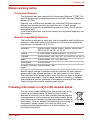
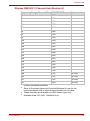
Network Compatibility Statement
This product is designed to work with, and is compatible with the following
networks. It has been tested to and found to conform with the additional
requirements conditional in EG 201 121.
Germany
ATAAB AN005, AN006, AN007, AN009, AN010 and
DE03, 04, 05, 08, 09, 12, 14, 17
Greece
ATAAB AN005, AN006 and GR01, 02, 03, 04
Portugal
ATAAB AN001, 005, 006, 007, 011 and P03, 04, 08, 10
Spain
ATAAB AN005, 007, 012, and ES01
Switzerland
ATAAB AN002
All other countries/ ATAAB AN003, 004
region
Specific switch settings or software setup are required for each network,
please refer to the relevant sections of the user guide for more details.
The hookflash (timed break register recall) function is subject to separate
national type approvals. It has not been tested for conformity to national
type regulations, and no guarantee of successful operation of that specific
function on specific national networks can be given.
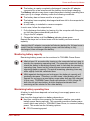
Following information is only for EU-member states:
The use of the symbol indicates that this product may not be
treated as household waste. By ensuring this product is
disposed of correctly, you will help prevent potential negative
consequences for the environment and human health, which
could otherwise be caused by inappropriate waste handling of
this product. For more detailed information about recycling of
this product, please contact your local city office, your
household waste disposal service or the shop where you
purchased the product.
User’s Manual
v
TOSHIBA A100
Optical disk drive safety instructions
TOSHIBA A100 computer is shipped with one of the following drives
preinstalled: DVD-ROM, CD-RW/DVD-ROM, or DVD Super Multi (+-R DL)
drive.
The optical disc drive employs a laser system. To ensure proper use of this
product, please read the manual carefully and retain for future reference.
Should the unit ever require maintenance, contact an authorized service
location.
Use of controls, adjustments or the performance of procedures other than
those specified may result in hazardous radiation exposure.
To prevent direct exposure to the laser beam, do not try to open the
enclosure.
USE OF CONTROLS OR ADJUSTMENTS OR PERFORMANCE OF
PROCEDURES OTHER THAN THOSE SPECIFIED IN THE MANUAL
MAY RESULT IN HAZARDOUS RADIATION EXPOSURE.
The optical drive that is used in this computer is equipped with a laser
device. A classification label with the following sentence is affixed to the
surface of the drive.
CLASS 1 LASER PRODUCT
LASER KLASSE 1
LUOKAN 1 LASERLAITE
APPAREIL A LASER DE CLASSE1
KLASS 1 LASER APPARAT
CLASS 1 LASTER PRODUCT
LASERSCHUTZKLASSE 1
PRODUKT
TO EN 60825
ADVERSEL: USYNLIG
LASERSTRÅLING VED ÅBNING,
NÅR SIKKERHEDSAF-BRYDER
ER UDE AF FUNKTION.
UNDGÅ UDSÆTTELSE FOR
STRÅLING
A drive with the label above is certified by the manufacturer that the drive
complies with the requirement for laser product on the date of
manufacturing pursuant to article 21 of Code of Federal Regulations by the
United States of America, Department of Health & Human Services, Food
and Drug Administration (DHHS 21 CFR).
In other countries, the drive is certified to comply with the requirement
pursuant to IEC 825 and EN60825 on class 1 laser product.
User’s Manual
vi
TOSHIBA A100
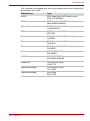
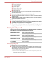
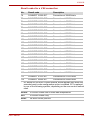
This computer is equipped with one of the optical drive in the following list
according to the model:
User’s Manual
Manufacturer
Type
HLDS
DVD Super Multi (±R Double Layer)
GSA-T10-ATAKK0
HLDS
DVD Super Multi (±R Double Layer)
GMA-4082N-ATAKK0
Matsushita
DVD Super Multi (±R Double Layer)
UJ-841BTJV-A
NEC
DVD Super Multi (±R Double Layer)
ND-7550
Panasonic
DVD Super Multi (±R Double Layer)
UJ-850B
Pioneer
DVD Super Multi (±R Double Layer)
DVD-K16
Teac
DVD Super Multi (±R Double Layer)
DV-W28E
Teac
CD-RW/DVD ROM
DW-224ER
HLDS
CD-RW/DVD ROM
GCC-4244-ATAKK0
Panasonic
CD-RW/DVD ROM
UJDA 770
Toshiba Samsung
CD-RW/DVD ROM
TS-L-462C
Toshiba Samsung
DVD ROM
SD-C2732
vii
TOSHIBA A100
Important Notice
Copyrighted works including, but not limited to music, video, computer
program, databases are protected by copyright laws. Unless specifically
permitted under applicable copyright laws, you cannot copy, modify, assign,
transmit or otherwise dispose of any copyrighted work with the consent of
the owner of the copyright. Please take notice that unauthorized copying,
modification, assignment, transmission and disposition may be subject to
claims for damages and penalties.
■ Avoid using a telephone (other than a cordless type) during an electrical
storm. There may be a remote risk of electric shock from lightning.
■ Do not use the telephone to report a gas leak in the vicinity of the leak.
■ Use only the power cord indicated in this manual.
■ Replace only with the same or equivalent type battery recommended by
the manufacturer.
■ Dispose of used batteries according to the manufacturer’s instructions.
Use only the battery pack that came with the computer or an optional
battery pack. Use of wrong battery could damage your computer
TOSHIBA assumes no liability for any damage in such case.
User’s Manual
viii
Table of Contents
Chapter 1
Introduction
Equipment checklist. . . . . . . . . . . . . . . . . . . . . . . . . . . . . . . . . . . . . . . 1-1
Features. . . . . . . . . . . . . . . . . . . . . . . . . . . . . . . . . . . . . . . . . . . . . . . . . 1-3
Special Features . . . . . . . . . . . . . . . . . . . . . . . . . . . . . . . . . . . . . . . . . . 1-9
TOSHIBA Value Added Package . . . . . . . . . . . . . . . . . . . . . . . . . . . . 1-11
Utilities and Application. . . . . . . . . . . . . . . . . . . . . . . . . . . . . . . . . . . 1-12
Options . . . . . . . . . . . . . . . . . . . . . . . . . . . . . . . . . . . . . . . . . . . . . . . . 1-14
Chapter 2
The Grand Tour
Front with the display closed . . . . . . . . . . . . . . . . . . . . . . . . . . . . . . . 2-1
Left side . . . . . . . . . . . . . . . . . . . . . . . . . . . . . . . . . . . . . . . . . . . . . . . . . 2-2
Right side . . . . . . . . . . . . . . . . . . . . . . . . . . . . . . . . . . . . . . . . . . . . . . . 2-4
Back side. . . . . . . . . . . . . . . . . . . . . . . . . . . . . . . . . . . . . . . . . . . . . . . . 2-5
Underside . . . . . . . . . . . . . . . . . . . . . . . . . . . . . . . . . . . . . . . . . . . . . . . 2-6
Front with the display open . . . . . . . . . . . . . . . . . . . . . . . . . . . . . . . . . 2-7
AV Buttons . . . . . . . . . . . . . . . . . . . . . . . . . . . . . . . . . . . . . . . . . . . . . . 2-8
System indicators. . . . . . . . . . . . . . . . . . . . . . . . . . . . . . . . . . . . . . . . . 2-9
Keyboard indicators . . . . . . . . . . . . . . . . . . . . . . . . . . . . . . . . . . . . . . 2-10
USB diskette drive . . . . . . . . . . . . . . . . . . . . . . . . . . . . . . . . . . . . . . . 2-11
Optical Media drive. . . . . . . . . . . . . . . . . . . . . . . . . . . . . . . . . . . . . . . 2-11
Chapter 3
Getting Started
Connecting the AC adaptor . . . . . . . . . . . . . . . . . . . . . . . . . . . . . . . . .
Opening the display . . . . . . . . . . . . . . . . . . . . . . . . . . . . . . . . . . . . . . .
Turning on the power . . . . . . . . . . . . . . . . . . . . . . . . . . . . . . . . . . . . . .
Starting up for the first time . . . . . . . . . . . . . . . . . . . . . . . . . . . . . . . .
Turning off the power . . . . . . . . . . . . . . . . . . . . . . . . . . . . . . . . . . . . . .
Restarting the computer . . . . . . . . . . . . . . . . . . . . . . . . . . . . . . . . . . .
System Recovery Options . . . . . . . . . . . . . . . . . . . . . . . . . . . . . . . . . .
User’s Manual
3-2
3-2
3-3
3-4
3-4
3-7
3-7
ix
TOSHIBA A100
Chapter 4
Operating Basics
Using the Touch Pad . . . . . . . . . . . . . . . . . . . . . . . . . . . . . . . . . . . . . . 4-1
Using the USB diskette drive . . . . . . . . . . . . . . . . . . . . . . . . . . . . . . . 4-2
Using optical media drives . . . . . . . . . . . . . . . . . . . . . . . . . . . . . . . . . 4-3
AV Button function (Provided with some models) . . . . . . . . . . . . . . 4-7
Writing CDs on CD-RW/DVD-ROM drive. . . . . . . . . . . . . . . . . . . . . . . 4-8
Writing CD/DVDs on DVD Super Multi (+-R DL) drive . . . . . . . . . . . 4-10
TOSHIBA Disc Creator . . . . . . . . . . . . . . . . . . . . . . . . . . . . . . . . . . . . 4-13
Data Verification . . . . . . . . . . . . . . . . . . . . . . . . . . . . . . . . . . . . . . . . . 4-14
Video . . . . . . . . . . . . . . . . . . . . . . . . . . . . . . . . . . . . . . . . . . . . . . . . . . 4-14
When using Ulead DVD MovieFactory® for TOSHIBA: . . . . . . . . . . 4-15
Media care . . . . . . . . . . . . . . . . . . . . . . . . . . . . . . . . . . . . . . . . . . . . . . 4-17
Modem (Provided with some models) . . . . . . . . . . . . . . . . . . . . . . . 4-18
Wireless communications . . . . . . . . . . . . . . . . . . . . . . . . . . . . . . . . . 4-20
LAN . . . . . . . . . . . . . . . . . . . . . . . . . . . . . . . . . . . . . . . . . . . . . . . . . . . 4-22
Cleaning the computer. . . . . . . . . . . . . . . . . . . . . . . . . . . . . . . . . . . . 4-24
Moving the computer . . . . . . . . . . . . . . . . . . . . . . . . . . . . . . . . . . . . . 4-24
Heat dispersal . . . . . . . . . . . . . . . . . . . . . . . . . . . . . . . . . . . . . . . . . . . 4-25
Chapter 5
The Keyboard
Typewriter keys. . . . . . . . . . . . . . . . . . . . . . . . . . . . . . . . . . . . . . . . . . .
F1 ... F12 function keys . . . . . . . . . . . . . . . . . . . . . . . . . . . . . . . . . . . .
Soft keys: Fn key combinations . . . . . . . . . . . . . . . . . . . . . . . . . . . . .
Windows special keys . . . . . . . . . . . . . . . . . . . . . . . . . . . . . . . . . . . . .
Keypad overlay . . . . . . . . . . . . . . . . . . . . . . . . . . . . . . . . . . . . . . . . . . .
Generating ASCII characters . . . . . . . . . . . . . . . . . . . . . . . . . . . . . . . .
Chapter 6
5-1
5-2
5-2
5-5
5-5
5-7
Power and Power-Up Modes
Power conditions . . . . . . . . . . . . . . . . . . . . . . . . . . . . . . . . . . . . . . . . . 6-1
Power indicators. . . . . . . . . . . . . . . . . . . . . . . . . . . . . . . . . . . . . . . . . . 6-2
Battery types. . . . . . . . . . . . . . . . . . . . . . . . . . . . . . . . . . . . . . . . . . . . . 6-3
Care and use of the battery pack . . . . . . . . . . . . . . . . . . . . . . . . . . . . 6-4
Replacing the battery pack . . . . . . . . . . . . . . . . . . . . . . . . . . . . . . . . 6-10
Starting the computer by password . . . . . . . . . . . . . . . . . . . . . . . . . 6-12
Power-up modes. . . . . . . . . . . . . . . . . . . . . . . . . . . . . . . . . . . . . . . . . 6-13
Chapter 7
HW Setup and Passwords
HW Setup. . . . . . . . . . . . . . . . . . . . . . . . . . . . . . . . . . . . . . . . . . . . . . . . 7-1
User’s Manual
x
TOSHIBA A100
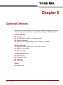
Chapter 8
Optional Devices
PC cards . . . . . . . . . . . . . . . . . . . . . . . . . . . . . . . . . . . . . . . . . . . . . . . . 8-2
Express Card . . . . . . . . . . . . . . . . . . . . . . . . . . . . . . . . . . . . . . . . . . . . 8-3
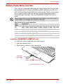
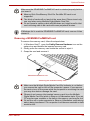
Multiple Digital Media Card Slot . . . . . . . . . . . . . . . . . . . . . . . . . . . . . 8-5
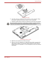
Memory expansion . . . . . . . . . . . . . . . . . . . . . . . . . . . . . . . . . . . . . . . . 8-7
Additional battery pack (6 Cell, 9 Cell and 12 Cell) . . . . . . . . . . . . . 8-10
Additional AC adaptor . . . . . . . . . . . . . . . . . . . . . . . . . . . . . . . . . . . . 8-10
Battery charger . . . . . . . . . . . . . . . . . . . . . . . . . . . . . . . . . . . . . . . . . . 8-10
USB FDD Kit . . . . . . . . . . . . . . . . . . . . . . . . . . . . . . . . . . . . . . . . . . . . 8-10
External monitor . . . . . . . . . . . . . . . . . . . . . . . . . . . . . . . . . . . . . . . . . 8-10
Television . . . . . . . . . . . . . . . . . . . . . . . . . . . . . . . . . . . . . . . . . . . . . . 8-11
i.LINK (IEEE1394) . . . . . . . . . . . . . . . . . . . . . . . . . . . . . . . . . . . . . . . . 8-11
Chapter 9
Troubleshooting
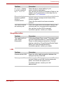
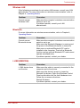
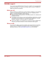
Problem solving process . . . . . . . . . . . . . . . . . . . . . . . . . . . . . . . . . . . 9-1
Hardware and system checklist . . . . . . . . . . . . . . . . . . . . . . . . . . . . . 9-3
TOSHIBA support . . . . . . . . . . . . . . . . . . . . . . . . . . . . . . . . . . . . . . . . 9-18
Chapter 10
Disclaimers
Appendix A
Specifications
Appendix B
Display Controller and Modes
Appendix C
V.90/V.92
Appendix D
Wireless LAN
Appendix E
AC Power Cord and Connectors
Appendix F
If your computer is stolen
Glossary
Index
User’s Manual
xi
Preface
Congratulations on your purchase of the TOSHIBA A100 computer. This
powerful, lightweight notebook computer is designed to provide years of
reliable, high-performance computing.
This manual tells how to set up and begin using your Toshiba A100
computer. It also provides detailed information on configuring your
computer, basic operations and care, using optional devices and
troubleshooting.
If you are a new user of computers or if you’re new to portable computing,
first read over the Introduction and The Grand Tour chapters to familiarize
yourself with the computer’s features, components and accessory devices.
Then read Getting Started for step-by-step instructions on setting up your
computer.
If you are an experienced computer user, please continue reading the
preface to learn how this manual is organized, then become acquainted
with this manual by browsing through its pages. Be sure to look over the
Special Features section of the Introduction, to learn about features that
are uncommon or unique to the computers and carefully read HW Setup
and Passwords. If you are going to install PC cards or connect external
devices such as a printer, be sure to read Chapter 8, Optional Devices.
Manual contents
This manual is composed of ten chapters, five appendixes, a glossary, and
an index.
Chapter 1, Introduction, is an overview of the computer’s features,
capabilities, and options.
Chapter 2, The Grand Tour, identifies the components of the computer and
briefly explains how they function.
Chapter 3, Getting Started, provides a quick overview of how to begin
operating your computer and gives tips on safety and designing your work
area.
User’s Manual
xii
TOSHIBA A100
Chapter 4, Operating Basics, includes tips on care of the computer and on
using the Touch Pad, optical media drive, external diskette drive, Wireless
LAN, LANs, Audio/Video controls, and internal modem.
Chapter 5, The Keyboard, describes special keyboard functions including
the keypad overlay and hot keys.
Chapter 6, Power and Power-Up Modes, gives details on the computer’s
power resources and battery save modes.
Chapter 7, HW Setup and Passwords, explains how to configure the
computer using the HW Setup program. It also tells how to set a password.
Chapter 8, Optional Devices, describes the optional hardware available.
Chapter 9, Troubleshooting, provides helpful information on how to perform
some diagnostic tests, and suggests courses of action if the computer
doesn’t seem to be working properly.
Chapter 10, Disclaimers, states the Disclaimer(s) information applicable to
TOSHIBA computer.
The Appendixes provide technical information about your computer.
The Glossary defines general computer terminology and includes a list of
acronyms used in the text.
The Index quickly directs you to the information contained in this manual.
Conventions
This manual uses the following formats to describe, identify, and highlight
terms and operating procedures.
Abbreviations
On first appearance, and whenever necessary for clarity, abbreviations are
enclosed in parentheses following their definition. For example: Read Only
Memory (ROM). Acronyms are also defined in the Glossary.
Icons
Icons identify ports, dials, and other parts of your computer. The indicator
panel also uses icons to identify the components it is providing information
on.
Keys
The keyboard keys are used in the text to describe many computer
operations. A distinctive typeface identifies the key top symbols as they
appear on the keyboard. For example, Enter identifies the Enter key.
User’s Manual
xiii
TOSHIBA A100
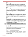
Key operation
Some operations require you to simultaneously use two or more keys. We
identify such operations by the key top symbols separated by a plus sign
(+). For example, Ctrl + C means you must hold down Ctrl and at the same
time press C. If three keys are used, hold down the first two and at the
same time press the third.
ABC
When procedures require an action such as clicking an icon
or entering text, the icon’s name or the text you are to type in
is represented in the type face you see to the left.
Display
ABC
Names of Windows or icons or text generated by the
computer that appears on its display screen is presented in
the type face you see to the left.
Messages
Messages are used in this manual to bring important information to your
attention. Each type of message is identified as shown below.
Pay attention! A caution informs you that improper use of equipment or
failure to follow instructions may cause data loss or damage your
equipment.
Please read. A note is a hint or advice that helps you make best use of
your equipment.
Terminology
This term is defined in this document as follows:
Start
User’s Manual
The word "Start" refers to the "
Windows Vista™.
" button in Microsoft®
xiv
General Precautions
TOSHIBA computers are designed to optimize safety, minimize strain and
withstand the rigors of portability. However, certain precautions should be
observed to further reduce the risk of personal injury, damage to the
computer or impared performance.
Be certain to read the general precautions below and to note the cautions
included in the text of the manual.
Stress injury
Carefully read the Instruction Manual for Safety & Comfort. It contains
information on prevention of stress injuries to your hands and wrists than
can be caused by extensive keyboard use. Chapter 3, Getting Started, also
includes information on work space design, posture and lighting that can
help reduce physical stress.
Heat injury
■ Avoid prolonged physical contact with the computer. If the computer is
used for long periods, its surface can become very warm. While the
temperature will not feel hot to the touch, if you maintain physical
contact with the computer for a long time (if you rest the computer on
your lap, or if you keep your hands on the palm rest, for example) your
skin might suffer low-heat injury.
■ If the computer has been used for a long time, avoid direct contact with
the metal plate supporting the I/O ports. It can become hot.
■ The surface of the AC adaptor can become hot when in use. This
condition does not indicate a malfunction. If you need to transport the
AC adaptor, disconnect it and let it cool before moving it.
■ Do not lay the AC adaptor on a material that is sensitive to heat. The
material could be damaged.
User’s Manual
xv
TOSHIBA A100
Pressure or impact damage
Do not apply heavy pressure to the computer or subject it to strong impact.
Excessive pressure or impact can cause damage to computer components
or otherwise cause malfunctions.
PC card overheating
Some PC cards can become hot with prolonged use. Overheating of a PC
card can result in errors or instability in the PC card operation. Also be
careful when you remove a PC card that has been used for a long time.
Mobile phone
Use of mobile phones can interfere with the audio system. Computer
operation is not impaired but it is recommended that a distance of 30 cm be
maintained between the computer and a mo-bile phone in use.
User’s Manual
xvi
Chapter 1
Introduction
This chapter provides an equipment checklist, and it identifies the
computer’s features, options and accessories.
Some of the features described in this manual may not function properly if
you use an operating system that was not pre- installed by TOSHIBA.
Equipment checklist
Carefully unpack your computer. Save the box and packing materials for
future use.
Hardware
Check to make sure you have all the following items:
■ Toshiba A100 Portable Personal Computer
■ Universal AC adaptor and power cord
■ Modular cable (Provided with some models)
User’s Manual
1-1
Introduction
Software
Windows Vista™
■ The following software is preinstalled:
■ Microsoft® Windows Vista™
■ Modem Driver
■ Display Drivers for Windows
■ Wireless LAN driver (Can be used only for Wireless LAN models)
■ Sound Driver for Windows
■ LAN Drivers
■ Bluetooth Driver (Can be used only for Bluetooth models)
■ Pointing Device Driver
■ Toshiba Value Added Package
■ TOSHIBA Power Saver
■ TOSHIBA User’s Manual
■ TOSHIBA Assist
■ TOSHIBA ConfigFree
■ TOSHIBA PC Diagnostic Tool
■ TOSHIBA Zooming Utility
■ TOSHIBA CD/DVD Drive Acoustic Silencer
■ TOSHIBA SD Memory Utilities
SD Memory Card Format Utility and other SD functions are packaged into
TOSHIBA SD Memory Utilities. When uninstalling the SD utilities, click
, Control Panel, Uninstall a program, and select TOSHIBA SD
Memory Utilities.
■
■
■
■
TOSHIBA Disc Creator
Symantec Norton Internet Security (NIS) 2007
InterVideo WinDVD
Ulead DVD MovieFacotry® for TOSHIBA
Documentation:
■ A100 Quickstart
■ A100 Portable Personal Computer User’s Manual
■ Microsoft® Windows Vista™ Quick Start Guide (provided with some
models)
■ Instruction Manual for Safety & Comfort
■ Warranty Information
User’s Manual
1-2
Introduction
Backup media and additional Software
■ Product Recovery DVD-ROM
■ Windows Anytime Upgrade DVD (provided in some regions)
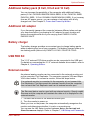
Features
The computer uses TOSHIBA’s advanced Large Scale Integration (LSI),
Comple-mentary Metal-Oxide Semiconductor (CMOS) technology
extensively to provide compact size, minimum weight, low power usage,
and high reliability. This computer incorporates the following features and
benefits:
Please visit your region’s website for the configuration details of the model
that you have purchased.
Processor
Built-in
Depending on the model you purchased:
■ Intel® Celeron® M Processor 410 or higher.
■ Intel® Core™ Solo Processor T1300 or higher.
■ Intel® Core™ Duo Processor T2250 or higher.
■ Intel® Core™ 2 Duo Processor T5200 or
higher.
■ Intel Pentium 2060 Processor.
Memory
Slots
PC2-4200 or PC2-5300 256MB, 512 MB, 1024 MB
or 2048 MB memory modules can be installed in
the two memory slots for a maximum of 4096 MB
system memory.
Video RAM
Depending on the model you purchased.
Intel® 945GM/943GML/940GML model:
Up to 128 MB integrated solution shares with main
memory.
nVIDIA® Geforce® Go 7600/7300 model:
■ External 64/128/256 MB
(Depending on model you purchased)
User’s Manual
1-3
Introduction
Disks
User’s Manual
Hard disk drive
The computer has an integrated, 2 1/2" hard disk
drive (HDD) for nonvolatile storage of data and
software. It comes in the following sizes.
■ 40 GB (37.26 billion bytes)
■ 60 GB (55.89 billion bytes)
■ 80 GB (74.52 billion bytes)
■ 100 GB (93.15 billion bytes)
■ 120 GB (111.78 billion bytes)
■ 160 GB (130.41 billion bytes)
■ 200 GB (186.26 billion bytes)
DVD-ROM drive
A full-size, DVD-ROM drive module lets you run
either digital versatile or compact disks without
using an adaptor. It runs DVD-ROMs at maximum
8 speed and CD-ROMs at maximum 24 speed.
This drive supports the same formats as the
CD-ROM drive plus the following:
■ DVD-ROM
■ DVD-Video
CD-RW/DVD-ROM
drive
Some models are equipped with a full-size,
CD-RW/DVD-ROM drive module that lets you run
CD/DVDs without using an adaptor. It reads
DVD-ROMs at maximum 8 speed and CD-ROMs
at maximum 24 speed. It writes CD-R at up to 24
speed and CD-RW at up to 24 speed. See
Chapter 4, Operating Basics, for details. For
reading, this drive supports the same formats as
the DVD-ROM drive.
1-4
Introduction
DVD Super Multi
(+-R DL) drive
Some models are equipped with a full-size DVD
Super Multi (+- R DL) drive module that lets you
record data to rewritable CD/DVDs as well as run
either 12 cm (4.72") or 8 cm (3.15") CD/DVDs
without using an adaptor. It reads DVD-ROMs at
maximum 8 speed and CD-ROMs at maximum 24
speed. It writes CD-R at up to 24 speed, CD-RW at
up to 16 speed, DVD-R at up to 8 speed and
DVD-RW at maximum 6 speed and DVD-RAM at
maximum 5 speed. DVD+R at up to 8 speed and
DVD+RW at up to 8 speed. DVD+R DL at up to 4
speed and DVD-R DL at up to 4 speed. This drive
supports the same formats as the DVD-ROM
drive.
■ DVD-ROM
■ DVD-Video
■ DVD-R
■ DVD-RW
■ DVD+R
■ DVD+RW
■ DVD-RAM
■ DVD+R DL
■ DVD-R DL
■ CD-DA
■ CD-Text
■ Photo CD (single/multi-session)
■ CD-ROM Mode 1, Mode 2
■ CD-ROMXA Mode 2 (Form1, Form2)
■ Enhanced CD (CD-EXTRA)
■ CD-G (Audio CD only)
■ Addressing Method 2
Display
The computer’s LCD panel supports high-resolution video graphics. The
screen can be set at a wide range of viewing angles for maximum comfort
and readability.
Built-in
User’s Manual
Thin-film transistor color LCD is available in three
sizes:
■ 15.4" WXGA,
1280 horizontal × 800 vertical pixels
■ 15.4" WXGA-CSV,
1280 horizontal × 800 vertical pixels
■ 15.4" WSXGA+-CSV,
1680 horizontal × 1050 vertical pixels
1-5
Introduction
Graphics
controller
Graphics controller maximizes display performance.
Refer to Appendix B for more information.
Keyboard
Built-in
85 keys or 86 keys, compatible with IBM®
enhanced keyboard, embedded numeric overlay,
dedicated cursor control,
and
keys. See
Chapter 5, The Keyboard, for details.
Pointing Device
Built-in
A Touch Pad and control buttons in the palm rest
enable control of the on-screen pointer.
Power
Battery pack
The computer is powered by one rechargeable
lithium-ion battery pack.
RTC battery
The internal RTC battery backs up the Real Time
Clock (RTC) and calendar.
AC adaptor
The universal AC adaptor provides power to the
system and recharges the batteries when they are
low. It comes with a detachable power cord.
Because it is universal, it can receive a range of
AC voltage between 100 and 240 volts.
Ports
User’s Manual
Headphone
Enables connection of a stereo headphone.
Microphone
Enables connection of a monaural microphone.
External monitor
15-pin, analog VGA port supports VESA DDC2B
compatible functions.
Universal Serial
Bus (USB2.0)
Four Universal Serial Bus (USB) enables chain
connection of a number of USB-equipped devices
to one port on your computer.
i.LINK™
(IEEE 1394)
This port enables high-speed data transfer directly
from external devices such as digital video
camera.
(Provided with some models)
Video Out Jack
This S-Video out port lets you transfer NTSC or
PAL data to external devices.
1-6
Introduction
Slots
PC card
A PC card slot accommodates:
One 5 mm Type II card
Refer to Chapter 8, Optional Devices, for details
Multiple Digital
Media Card
This slot lets you easily transfer data from devices,
such as digital cameras and Personal Digital
Assistants, that use flash memory (SD/MS/MS
Pro/MMC/xD memory cards).
(Provided with some models)
Express card
(depending on
model purchased)
This slot allows you to install a Express Card™/34
or Express Card™/54 to expand functionality.
(Provided with some models)
Multimedia
Sound System
Sound Blaster™ Pro™ and Windows Sound
System compatible sound system provides
internal speaker as well as jacks for an external
microphone and headphone. It also has a volume
control dial.
S-Video Out Port
This S-Video out port lets you transfer NTSC or
PAL data to external devices. See Chapter 8,
Television, for details.
Communications
LAN
User’s Manual
The computer is equipped with a LAN card that
supports Ethernet LAN (10 Mbit/s, 10BASE-T),
Fast Ethernet LAN (100 Mbit/s, 100BASE-TX).
1-7
Introduction
User’s Manual
Wireless LAN
Some computers in this series are equipped with a
Wireless LAN mini card that is compatible with
other LAN systems based on Direct Sequence
Spread Spectrum/Orthogonal Frequency Division
Multiplexing radio technology that complies with
the IEEE 802.11 Standard (Revision A, B and G).
■ Automatic Transmit Rate Select mechanism in
the transmit range of 54, 48, 36, 24, 18, 12, 9
and 6 Mbit/s (Revision A/B, B/G, A/B/G combo
type).
■ Automatic Transmit Rate Select mechanism in
the transmit range of 11, 5.5, 2 and 1 Mbit/s
(Revision B).
■ Frequency Channel Selection (5 GHz:
Revision A/2.4 GHz: Revision B/G).
■ Roaming over multiple channels.
■ Card Power Management.
■ Wired Equivalent Privacy (WEP) data
encryption, based on 128 bit encryption
algorithm (Intel module type).
■ Advanced Encryption Standard (AES) data
encryption, based on 256 bit encryption
algorithm (Atheros module type).
Modem
(Provided with
some models)
Some computers in this series are equipped with
an internal modem. The internal modem provides
capability for data and fax communication. It
supports V.90 (V.92). Refer to V.90/V.92 section in
Appendix C. The speed of date transfer and fax
depends on analog telephone line conditions. It
has a modem jack for connecting to a telephone
line. It is preinstalled as a standard device in some
markets. Both of V.90 and V.92 are supported only
in USA, Canada and Australia. Only V.90 is
available in other regions.
Bluetooth
Some computers in this series are equipped with
Bluetooth functions. Bluetooth wireless technology
eliminates the need for cables between electronic
devices such as computers and printers. Bluetooth
provides fast, reliable, and secure wireless
communication in a small space.
Wireless
Communication
Switch
This switch turns the Wireless LAN and Blurtooth
function on and off.
(Provided with some models)
1-8
Introduction
Security
Security lock slot
Connects an optional security lock to anchor the
computer to a desk or other large object.
Software
Operating System
Windows Vista™ is available. Refer to the
preinstalled software section at the front of this
chapter.
TOSHIBA Utilities
A number of utilities and drivers are preinstalled to
make your computer more convenient to use.
Refer to the Utilities section in this chapter.
Plug and Play
When you connect an external device to the
computer or when you install a component, Plug
and Play capability enables the system to
recognize the connection and make the necessary
configurations automatically.
Special Features
The following features are either unique to TOSHIBA computers or are
advanced features, which make the computer more convenient to use.
User’s Manual
Hot keys
Key combinations let you quickly modify the
system configuration directly from the keyboard
without running a system configuration program.
Display automatic
power off
This feature automatically cuts off power to the
internal display when there is no keyboard input for
a time specified. Power is restored when any key
is pressed. You can specify the time in the Monitor
power off item of the Basic Setup tab in TOSHIBA
Power Saver.
HDD automatic
power off
This feature automatically cuts off power to the
hard disk drive when it is not accessed for a time
specified. Power is restored when the hard disk is
accessed. You can specify the time in the HDD
Power off item of the Basic Setup tab in TOSHIBA
Power Saver.
System automatic
Sleep/Hibernation
This feature automatically shuts down the system
in sleep mode or Hibernation mode when there is
no input or hardware access for a time specified.
You can specify the time and select either System
Sleep or System hibernation in the System sleep
and System item of the Basic Setup tab in
TOSHIBA Power Saver.
1-9
Introduction
User’s Manual
Keypad overlay
A ten-key pad is integrated into the keyboard.
Refer to the Keypad overlay section in Chapter 5,
The Keyboard, for instructions on using the
keypad overlay.
Power on
password
Two levels of password security, supervisor and
user, are available to prevent unauthorized access
to your computer.
Instant security
A hot key function blanks the screen and disables
the computer providing data security.
Intelligent power
supply
A microprocessor in the computer’s intelligent
power supply detects the battery’s charge and
calculates the remaining battery capacity. It also
protects electronic components from abnormal
conditions, such as voltage overload from an AC
adaptor. You can monitor remaining battery
capacity. Use the Battery remaining item in
TOSHIBA Power Saver.
Battery save mode
This feature lets you save battery power. You can
specify the Power Save Mode in the Profile item in
TOSHIBA Power Saver.
Panel power on/off
This feature turns power to the computer off when
the display panel is closed and turns it back on
when the panel is opened. You can specify the
setting in the When I close the lid item of the Setup
Action tab in TOSHIBA Power Saver.
Low battery
automatic
hibernation
When battery power is exhausted to the point that
computer operation cannot be continued, the
system automatically enters Hibernation and shuts
down. You can specify the setting in the Setup
Action tab in TOSHIBA Power Saver.
Heat dispersal
To protect from overheating, the CPU has an
internal temperature sensor. If the computer’s
internal temperature rises to a certain level, the
cooling fan is turned on or the processing speed is
lowered. Use the Cooling Method item of the Basic
Setup tab in TOSHIBA Power Saver.
■ Maximum
Performance
Turns on fan first, then if
necessary lowers CPU
processing speed.
■ Battery
optimized
Lowers the CPU processing
speed first, then if necessary
turns on the fan.
1-10
Introduction
Hibernation
This feature lets you turn off the power without
exiting from your software. The contents of main
memory are saved to the hard disk, when you turn
on the power again, you can continue working right
where you left off. Refer to the Turning off the
power section in Chapter 3, Getting Started, for
details.
Sleep
If you have to interrupt your work, you can turn off
the power without exiting from your software. Data
is maintained in the computer’s main memory.
When you turn on the power again, you can
continue working right where you left off.
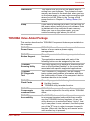
TOSHIBA Value Added Package
This section describes the TOSHIBA Component features pre-installed on
the computer.
User’s Manual
TOSHIBA
Power Saver
TOSHIBA Power Saver provides you with the
feature of more various power supply
managements.
TOSHIBA
Button Support
This utility controls the following computer button
functions.
The applications associated with each of the
following button can be assigned by the user.
TOSHIBA
Zooming Utility
This utility allows you to enlarge or reduce the icon
size on the Windows Desktop, or the zoom factor
associated with specific supported applications.
TOSHIBA
PC Diagnostic
Tool
The TOSHIBA PC Diagnostic Tool will display
basic system configuration information and allow
the functionality of some of the computer’s built-in
hardware devices to be tested.
TOSHIBA
Flash Cards
This utility supports the following functions.
■ Hot Key function.
■ TOSHIBA utility launcher function.
TOSHIBA
Components
common Driver
TOSHIBA Components Common Driver contains
the module required for the utility which TOSHIBA
offers.
TOSHIBA
Accessibility
The TOSHIBA Accessibility utility provides support
to movement impaired users when they need to
use the TOSHIBA Hot-key functions. In use, the
utility allows you to make the Fn key "sticky", that
is you can press it once, release it, and then press
one of the "F" keys in order to access its specific
function. When set, the Fn key will remain active
until another key is pressed.
1-11
Introduction
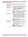
Utilities and Application
This section describes preinstalled utilities and tells how to start them. For
details on operations, refer to each utility’s online manual, help files or
readme.txt files.
TOSHIBA Assist
TOSHIBA Assist is a graphical user interface that
provides easy access to help and services.
HW Setup
To start the utility, click
, point to All
Programs, click TOSHIBA, click Utilities, and
select HWSetup icon.
DVD Video Player
The DVD Video Player is used to play DVD-Video.
It has an on-screen interface and functions. Click
, point to All Programs, point to InterVideo
WinDVD, then click InterVideo WinDVD.
TOSHIBA
Disc Creator
You can create CD/DVDs in several formats
including audio CDs that can be played on a
standard stereo CD player and data CD/DVDs to
store the files and folderson your hard disk drive.
This software can be used on a model with
CD-RW/DVD-ROM drive, DVD-R/-RW drive,
DVD+-R/+-RW drive and DVD Super Multi drive.
You can boot TOSHIBA Disc Creator from the
menu bar as follows.
- All Programs - TOSHIBA - CD&DVD
Applications - Disc Creator
TOSHIBA
DVD-RAM Utility
TOSHIBA DVD-RAM Utility has the function of
Physical Format and Write-Protect to DVD-RAM.
This utility is contained the setup module of
TOSHIBA Disc Creator.
You can boot TOSHIBA DVD-RAM Utility from the
menu bar as follows.
- All Programs - TOSHIBA - CD&DVD
Applications - DVD-RAM Utility
User’s Manual
1-12
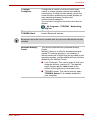
Introduction
TOSHIBA
ConfigFree
ConfigFree is a suite of utilities to allow easy
control of communication device and network
connections. ConfigFree also allows you to find
communication problems and create profiles for
easy switching between location and
communication networks.
You can boot ConfigFree from the menu bar as
follows.
- All Programs - TOSHIBA - Networking ConfigFree
Bluetooth
TOSHIBA Stack
This software enables communication between
remote Bluetooth devices.
Bluetooth cannot be used in models that do not have a Bluetooth module
installed.
Windows Mobility
Center
User’s Manual
This section describes the Windows Mobility
Center.
Mobility Center is a utility for accessing several
mobile PC settings quickly in one window. A
default maximum of eight tiles are provided by the
operating system, and an additional three tiles are
added to your Mobility Center.
■ Lock Computer: This can be used to lock your
computer without turning it off. This has the
same function as the Lock button at the
bottom of the right pane in the start menu.
■ TOSHIBA Assist: This can be used to open
TOSHIBA Assist if it is already installed in
your computer.
1-13
Introduction
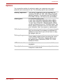
Options
You can add a number of options to make your computer even more
powerful and convenient to use. The following options are available:
User’s Manual
Memory expansion
Two memory expansion slots are available for
installing 256 MB, 512 MB, 1024 MB or 2048 MB
memory modules. The modules are PC2-4200 or
PC2-5300, 200-pin, SO Dual In-line (SO-DIMM).
Battery pack
An additional battery pack
6 cells Type (PA3399U-2BAS/PA3399U-2BRS),
9 cells Type (PA3478U-1BAS/PA3478U-1BRS),
12 cells Type (PA3400U-1BAS/PA3400U-1BRS)
can be purchased from your TOSHIBA dealer. The
battery pack is identical to the one that came with
your computer. Use it as a spare or replacement.
AC adaptor
If you use your computer at more than one site, it
may be convenient to purchase an additional AC
adaptor for each site so you will not have to carry
the adaptor with you.
Battery charger
The battery charger provides a convenient way to
charge battery packs without requiring the use of
your computer. The battery charger holds up to
two battery packs (lithiumion) PA3471U-1CHG,
PA3471E-1CHG.
USB diskette drive
A 3 1/2" diskette drive accommodates 1.44megabyte.
Security lock
A slot is available to attach a security cable to the
computer to deter theft.
1-14
Chapter 2
The Grand Tour
This chapter identifies the various components of your computer. Become
familiar with each component before you operate the computer.
Front with the display closed
Figure below shows the computer’s front with its display panel in the closed
position.
Multiple Digital Media
card slot
Display latch
Multiple Digital
Media card
indicator
System Indicators
Volume control
Microphone
Headphone
Front of the computer with display closed
User’s Manual
Display latch
This latch secures the LCD panel in its closed
position. Slide the latch to open the display.
Volume control
Use this dial to adjust the volume of the system
speaker and headphones.
Microphone jack
A standard 3.5 mm mini microphone jack enables
connection of a monaural microphone or other
device for audio input.
2-1
The Grand Tour
Headphone jack
A standard 3.5 mm mini headphone jack enables
connection of a stereo headphone (16 ohm
minimum) or other device for audio output. When
you connect headphones, the internal speaker is
automatically disabled.
Infrared receiver
window
Infrared receiver window is provided with some
models.
This is a sensor window that receives signals from
the remote control which is provided with your
computer.
Not supported by a Windows Vista™ model.
Multiple Digital
Media Card Slot
This slot lets you easily transfer data from devices,
such as digital camera and PDA, that use flash
memory (SD/MS/MS Pro/MMC/xD memory cards).
Multiple Digital
Media Card
Indicator
This LED glows blue when the computer is
accessing the memory card.
System Indicators
Four LEDs let you monitor the DC IN, Power
status, Main battery and Disk. Details are in the
System indicators sections.
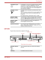
Left side
Figure below shows the computer’s left side.
Video-out jack
Fan vent
External monitor port
Express card slot (depending
on model purchased)
i.LINK (IEEE 1394) Port
PC card slot
The left side of the computer
User’s Manual
External monitor
port
This 15-pin port lets you connect an external
monitor.
Fan vent
Provides air flow for the fan.
2-2
The Grand Tour
Be careful not to block the fan vent. Also be careful to keep foreign objects
out of the vents. A pin or similar object can damage the computer’s
circuitry.
Video-out jack
Plug a 4-pin S-Video connector into this jack.
i.LINK (IEEE 1394)
Port
Connect an external device, such as a digital video
camera to this port for high-speed data transfer.
Some models are equipped with a i.LINK port.
(Provided with some models)
When multiple IEEE1394 devices are connected to a PC, the devices may
not correctly be identified. This problem may occur when Windows Vista™
is restarted while the devices are connected or when the power to the
IEEE1394 devices is turned on before the PC is turned on. If it occurs,
disconnect the IEEE1394 cables and then reconnect them.
PC Card Slot
The PC card slot can accommodate one 5 mm PC
card (Type II). The slot supports 16-bit PC card
and 32-bit CardBus PC card.
Keep foreign objects out of the PC card slot. A pin or similar object can
damage the computer’s circuitry.
Express Card
Depending on the model purchased, the computer
provides Express Card slot on its left side, which
allows you to install an additional Express card.
(Provided with some models)
EXPRESS CARD SLOT is upper and PC CARD SLOT is lower. When you
insert it, please pay attention since it causes the breakdown.
User’s Manual
2-3
The Grand Tour
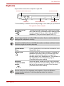
Right side
Figure below shows the computer’s right side.
Wireless communication switch
USB Ports
Security lock slot
Optical Media Drive
*Modem jack
*The availability of Modem Jack is depending on the model you purchased.
The right side of the computer
Universal Serial
Bus Ports
The two Universal Serial Bus (USB) ports comply
with USB Serial 2.0 standards, which enables data
transfer speeds 40 times faster than the USB 1.1
standards. (The ports also support USB 1.1)
Keep foreign objects out of the USB connectors. A pin or similar object can
damage the computer’s circuitry.
Operation of all functions of all USB devices has not been confirmed. some
functions might not execute properly.
Optical Media
Drive
A DVD-ROM drive, CD-RW/DVD-ROM drive, DVD
Super Multi drive.
Modem jack
In areas where an internal modem is installed as
standard equipment, there is a modem jack that
lets you use a modular cable to connect the
modem directly to a telephone line. The modem is
not supported in some marketing regions.
(Provided with some models)
Wireless
communication
switch
Slide this switch toward the right of the computer
to turn on Wireless communication. Slide it toward
the left of the computer to turn off the functions.
(Provided with some models)
Set the switch to off in airplanes and hospitals. Check the Wireless
communication indicator. It will stop glowing when the wireless
communication.
User’s Manual
2-4
The Grand Tour
Security lock slot
A security cable attaches to this slot. The optional
security cable anchors your computer to a desk or
other large object to deter theft.
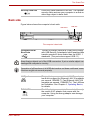
Back side
Figure below shows the computer’s back side.
USB Ports
LAN jack
DC IN 15V
The computer’s back side
Universal Serial
Bus Ports
The two Universal Serial Bus (USB) ports comply
with USB Serial 2.0 standards, which enables data
transfer speeds 40 times faster than the USB 1.1
standards. (The ports also support USB 1.1)
Keep foreign objects out of the USB connectors. A pin or similar object can
damage the computer’s circuitry.
Operation of all functions of all USB devices has not been confirmed. some
functions might not execute properly.
User’s Manual
LAN jack
This jack lets you connect to a LAN. The adaptor
has built-in support for Ethernet LAN (10 megabits
per second, 10BASE-T), Fast Ethernet LAN (100
megabits per second, 100BASE-Tx). The LAN has
two indicators. See Chapter 4, Operating Basics,
for details.
DC IN 15V
The AC adaptor connects to this socket. Use only
the model of AC adaptor that comes with the
computer. Using the wrong adaptor can damage
your computer.
2-5
The Grand Tour
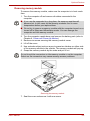
Underside
Figure below shows the underside of the computer. Make sure the display
is closed before turning over your computer.
Battery pack
Battery Release Latch
Battery Pack Lock
Memory module cover
The underside of the computer
User’s Manual
Battery pack
The battery pack powers the computer when the
AC adaptor is not connected. The Batteries
section in Chapter 6, Power and Power-Up
Modes, describes how to access the battery pack.
Additional battery packs can be purchased from
your TOSHIBA dealer to extend the computer’s
battery operating time.
Battery pack cover
latch
Slide this latch to release the battery pack.
This latch moves only when the computer is
upside down.
Battery lock
Slide the battery pack lock to unlocked position to
free the battery latch.
Memory module
cover
This cover protects two memory module sockets.
One or two modules are preinstalled.
2-6
The Grand Tour
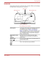
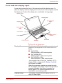
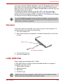
Front with the display open
Figure below shows the front of the computer with the display open. To
open the display, slide the display latch on the front of the computer and lift
the display up. Position the display at a comfortable viewing angle.
Display Screen
Display Hinge
Stereo Speaker
(Right)
Display Hinge
Stereo Speaker
(Left)
Power Button
Touch Pad Control
Buttons
Internet Button
CD/DVD Button
System
Indicators
Touch Pad
The front with the display open
User’s Manual
Display Screen
The full-color LCD displays high-contrast text and
graphics The computer’s LCD consist of one of
below:
■ 15.4" WXGA,
1280 horizontal × 800 vertical pixels.
■ 15.4" WXGA-CSV,
1280 horizontal × 800 vertical pixels.
■ 15.4" WSXGA+-CSV,
1680 horizontal × 1050 vertical pixels.
The computer has a Thin-Film Transistor (TFT)
display. Refer to Appendix B, Display Controller
and Modes for details.
When the computer operates on power through
the AC adaptor, the display screen’s image will be
somewhat brighter than when it operates on
battery power. The lower brightness level is
intended to save battery power.
Display Hinge
The display hinge holds the display screen at
easy-to-view angles.
2-7
The Grand Tour
Stereo Speaker
The speaker emits sound generated by your
software as well as audio alarms, such as low
battery condition, generated by the system.
Touch Pad
Moves the pointer and selects or activates items
on the screen. Can be set to perform other mouse
functions, such as scrolling, selecting, and doubleclicking.
Touch Pad
Control Buttons
Function like the left and right buttons on an
external mouse.
Power Button
Press the power button to turn the computer’s
power on and off. The Power button LED indicates
the status.
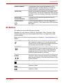
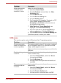
AV Buttons
Six buttons are provided with some models.
Available for use: Internet, CD/DVD, Play/Pause, Stop, Previous, Next.
These buttons allow you to manage Audio/Video, run applications and
access utilities.
Refer to the AV button function section in Chapter 4, Operating Basics for
details.
User’s Manual
Internet Button
Press this button to launch an Internet browser. If
the computer’s power is off, you can press this
button to turn on the computer’s power and launch
the browser automatically in one step.
CD/DVD Button
Press this button to launch a Windows Media
Player/WinDVD. If the computer’s power is off, you
can press this button to turn on the computer’s
power and launch the Windows Media Player/
WinDVD automatically in one step.
Play/Pause
button
Press this button to run Windows Media Player/
WinDVD. When Windows Media Player/WinDVD
was already running, this button becomes to Play/
Pause function.
STOP
Press this button to stop play.
Previous button
Press this button to advance to the previous track,
chapter or data.
Next button
Press this button to advance to the next track,
chapter or data.
2-8
The Grand Tour
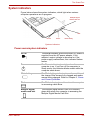
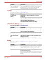
System indicators
Figure below shows the system indicators, which light when various
computer operations are in progress.
Multiple Digital
Media card slot
Disk
DC IN
Power
Main battery
Systems indicators
Power source/system indicators
User’s Manual
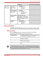
DC IN
The DC IN indicator glows blue when DC power is
supplied from the AC power adaptor. If the
adaptor’s output voltage is abnormal or if the
power supply malfunctions, this indicator flashes
amber.
Power
The Power indicator glows blue when the
computer is on. If you turn off the computer in
Sleep mode, this indicator blinks amber while the
computer shuts down.
Main battery
The Main battery indicator shows the condition of
the charge. Blue means fully charged and amber
means being charged. Refer to Chapter 6, Power
and Power-Up Modes.
Disk
The Disk indicator glows blue when the computer
is accessing a disk drive.
Multiple digital
media card slot
The Multiple digital Media Card Slot indicator
glows blue when the computer is accessing the
Multiple Digital Media Card Slot.
2-9
The Grand Tour
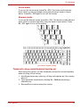
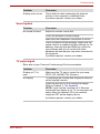
Keyboard indicators
The figures below show the positions of the keypad overlay indicators and
the CapsLock indicator.
When the F10 key indicator glows the keypad overlay lets you control the
cursor.
When the F11 key indicator glows the keypad overlay lets you enter
numbers.
Numeric mode
Arrow mode
Keypad overlay indicators
Arrow mode
When the Arrow mode indicator lights green, you
can use the keypad overlay (white labeled keys)
as cursor keys. Refer to the Keypad overlay
section in Chapter 5, The Keyboard.
Numeric mode
You can use the keypad overlay (white labeled
keys) for numeric input when the Numeric mode
indicator lights green. Refer to the Keypad overlay
section in Chapter 5, The Keyboard.
When the CapsLock indicator glows the keyboard is in all-caps mode.
Caps Lock Indicator
CapsLock indicator
Keyboard indicator
Caps Lock
User’s Manual
This indicator glows green when the alphabet keys
are locked in uppercase.
2-10
The Grand Tour
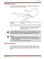
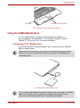
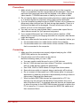
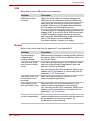
USB diskette drive
A 3 1/2" diskette drive accommodates 1.44-megabyte or 720-kilobyte
diskettes. It connects to the USB port.
Disk-In-Use
Indicator
Diskette slot
Eject button
USB diskette drive
Disk-In-Use
Indicator
This indicator lights when the diskette is being
accessed.
Diskette slot
Insert diskette in this slot.
Eject button
When a diskette is fully seated in the drive, the
eject button pops out. To remove a diskette, push
in the eject button and the diskette pops out
partially for removal.
Check the Disk-In-Use indicator when you use the diskette drive. Do not
press the eject button or turn off the computer while the light is glowing.
Doing so could destroy data and damage the diskette or the drive.
NOTES:
1. The external diskette drive should be placed on a flat, horizontal
surface when in use. Do not set the drive on an incline greater than 20°
while it is operating.
2. Do not set anything on top of the diskette drive.
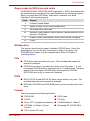
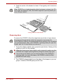
Optical Media drive
CD-RW/DVD-ROM drive, DVD-ROM drive, DVD Super Multi (+-R DL)
drive. An ATAPI interface controller is used for CD/DVD-ROM operation.
When the computer is accessing a CD/DVD, an indicator on the drive
glows.
User’s Manual
2-11
The Grand Tour
Region codes for DVD drives and media
CD-RW/DVD-ROM, DVD-ROM, DVD Super Multi (+-R DL) drive and media
are manufactured according to the specifications of six marketing regions.
When you purchase DVD-Video, make sure it matches your drive,
otherwise it will not play properly.
Code Region
1
Canada, United States
2
Japan, Europe, South Africa, Middle East
3
Southeast Asia, East Asia
4
Australia, New Zealand, Pacific Islands, Central America, South
America, Caribbean
5
Russia, Indian Subcontinent, Africa, North Korea, Mongolia
6
China
Writable discs
This section describes the types of writable CD/DVD discs. Check the
specifications for your drive to for the type of discs it can write. Use
TOSHIBA Disc Creator to write compact discs. Refer to Chapter 4,
Operating Basics.
CDs
■ CD-R discs can be written only once. The recorded data cannot be
erased or changed.
■ CD-RW discs can be recorded more than once. Use either 1, 2, or 4
multi speed CD-RW discs or high-speed 4- to 10-speed discs. The write
speed of the ultra-speed CD-RW discs (Ultra-speed is CD-RW/
DVD-ROM drive only) is maximum 24-speed.
DVDs
■ DVD-R, DVD+R and DVD+R DL discs can be written only once. The
recorded data cannot be erased or changed.
■ DVD-RW, DVD+RW and DVD-RAM discs can be recorded more than
once.
Formats
The drives support the following formats:
■ DVD-ROM
■ DVD-Video
■ CD-DA
■ CD-Text
■ Photo CD™ (single/multi-session) ■ CD-ROM Mode 1, Mode 2
■ CD-ROM x A Mode 2 (Form1,
Form2)
■ Enhanced CD (CD-EXTRA)
■ CD-G (Audio CD only)
User’s Manual
2-12
The Grand Tour
DVD-ROM drive
The full- size DVD-ROM drive module lets you record data to rewritable
CD/DVDs as well as run either 12 cm (4.72") or 8 cm (3.15") CD/DVDs
without using an adaptor.
The read speed is slower at the center of a disc and faster at the outer
edge.
DVD read
8 speed (maximum)
CD read
24 speed (maximum)
CD-RW/DVD-ROM drive
The full-size CD-RW/DVD-ROM drive module lets you record data to
rewritable CDs as well as run either 12 cm (4.72") or 8 cm (3.15") CD/DVDs
without using an adaptor.
The read speed is slower at the center of a disc and faster at the outer
edge.
DVD read
8 speed (maximum)
CD read
24 speed (maximum)
CD-R write
8 speed (maximum)
CD-RW write
10 speed (maximum, high-speed media)
24 speed (maximum, Ultra-speed media)
DVD Super Multi (+-R DL) drive
The full-size DVD Super Multi drive module lets you record data to s as
rewritable CDs as well as run either 12 cm (4.72") or 8 cm (3.15") CD/DVDs
without using an adaptor.
The read speed is slower at the center of a disc and faster at the outer
edge.
User’s Manual
DVD read
8 speed (maximum)
DVD-R write
8 speed (maximum)
DVD-RW write
6 speed (maximum)
DVD+R write
8 speed (maximum)
DVD+RW write
8 speed (maximum)
DVD+R DL write
4 speed (maximum)
DVD-R DL write
4 speed (maximum)
DVD-RAM write
5 speed (maximum)
CD-R write
24 speed (maximum)
CD-RW write
16 speed (maximum, ultra-speed media)
2-13
The Grand Tour
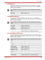
AC adaptor
The AC adaptor converts AC power to DC power and reduces the voltage
supplied to the computer. It can automatically adjust to any voltage from
100 to 240 volts and to a frequency of either 50 or 60 hertz, enabling you to
use the computer in almost any region.
To recharge the battery, simply connect the AC adaptor to a power source
and the computer. See Chapter 6 Power and Power-Up Modes for details.
The AC adaptor(2-pin plug)
The AC adaptor (3-pin plug)
Use of the wrong adaptor could damage your computer. TOSHIBA
assumes no liability for any damage in such case. The output rating for the
computer is 15 volts DC.
Please use only the AC adaptor supplied with the computer or an AC
adaptor certified by TOSHIBA.
User’s Manual
2-14
Chapter 3
Getting Started
This chapter provides basic information to get you started using your
computer. It covers the following topics:
Be sure also to read Instruction Manual for Safety & Comfort. This guide,
which is included with the computer, explains product liability.
■ Connecting the AC adaptor
■ Opening the display
■ Turning on the power
■ Windows Vista™ setup
■ Turning off the power
■ Restarting the computer
■ Restoring the Windows system
If you are a new user, follow the steps in each section of this chapter as you
prepare to operate your computer.
All users should be sure to carefully read the sections Windows Vista™
setup, which describe actions to take when you turn on the power for the
first time.
User’s Manual
3-1
Getting Started
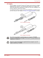
Connecting the AC adaptor
Attach the AC adaptor when you need to charge the battery or you want to
operate from AC power. It is also the fastest way to get started, because
the battery pack will need to be charged before you can operate from
battery power.
The AC adaptor can be connected to any power source supplying from 100
to 240 volts and 50 or 60 hertz. For details on using the AC adaptor to
charge the battery pack, refer to Chapter 6, Power and Power-Up Modes.
Use of the wrong adaptor could damage your computer. TOSHIBA
assumes no liability for any damage in such case. The output rating for the
computer is 15 volts DC.
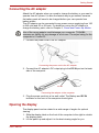
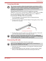
1. Connect the power cord to the AC adaptor.
Connecting the power cord to the AC adaptor
2. Connect the AC adaptor’s DC output plug to the DC IN port on the back
side of the computer.
DC-IN
Connecting the adaptor to the computer
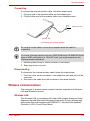
3. Plug the power cord into a live wall outlet. The Battery and DC IN
indicator on the front of the computer should glow.
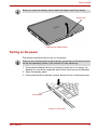
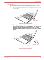
Opening the display
The display panel can be rotated in a wide range of angles for optimal
viewing.
1. Slide the display latch on the front of the computer to the right to unlatch
the display panel.
2. Lift the panel up and adjust it to the best viewing angle for you.
User’s Manual
3-2
Getting Started
When you open the display, hold it with both hands and lift up slowly.
Display latch
Opening the display panel
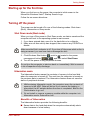
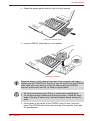
Turning on the power
This section describes how to turn on the power.
After you turn on the power for the first time, do not turn it off until you have
set up the operating system (OS) and the OS has started up.
1. If the external diskette drive is connected, make sure it is empty. If a
diskette is in the drive, press the eject button and remove the diskette.
2. Open the display panel.
3. Press and hold the computer’s power button for two or three seconds.
Power Button
Turning on the power
User’s Manual
3-3
Getting Started
Starting up for the first time
When you first turn on the power, the computer’s initial screen is the
Microsoft® Windows Vista™ Startup Screen Logo.
Follow the on-screen directions.
Turning off the power
The power can be turned off in one of the following modes: Shut down
(Boot), Hibernation or Sleep mode.
Shut Down mode (Boot mode)
When you turn off the power in Shut Down mode, no data is saved and the
computer will boot to the operating system’s main screen.
1. If you have entered data, save it to the hard disk or to a diskette.
2. Make sure all disc activity has stopped, then remove any CD/DVDs or
disette.
Make sure the Disk’s indicator is off. If you turn off the power while a disc is
being accessed, you can lose data or damage the disc.
3. Click Windows Start button
, point to
located in the power
management button
, and then select Shut Down.
4. Turn off the power to any peripheral devices.
Do not turn the computer or devices back on immediately. Wait a moment
to let all capacitors fully discharge.
Hibernation mode
The hibernation feature saves the contents of memory to the hard disk
when the computer is turned off. The next time the computer is turned on,
the previous state is restored. The hibernation feature does not save the
status of peripheral devices.
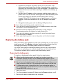
1. While entering hibernation mode, the computer saves the contents of
memory to the HDD. Data will be lost if you remove the battery or
disconnect the AC adaptor before the save is completed. Wait for the
Disk indicator to go out.
2. Do not install or remove a memory module while the computer is in
hibernation mode. Data will be lost.
Benefits of hibernation
The hibernation feature provides the following benefits:
■ Saves data to the hard disk when the computer automatically shuts
down because of a low battery.
User’s Manual
3-4
Getting Started
For the computer to shut down in hibernation mode, the hibernation feature
must be enabled in two places: the Hibernate tab in Power Options and
Setup Action tab in TOSHIBA Power Saver. Otherwise, the computer will
shut down in Sleep mode. If battery power becomes depleted, data saved
in Sleep mode will be lost.
■ You can return to your previous working environment immediately when
you turn on the computer.
■ Saves power by shutting down the system when the computer receives
no input or hardware access for the duration set by the System
hibernate feature.
■ You can use the panel power off feature.
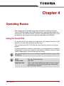
Starting Hibernation
To enter Hibernation mode, follow the steps below.
Windows Vista™
1. Click Windows Start button
.
2. Point to
located in the power management button
3. Select Hibernate.
.
Automatic Hibernation
The computer will enter Hibernate mode automatically when you press the
power button or close the lid. First, however, make the appropriate settings
according to the steps below.
1. Open the Control Panel.
2. Open Mobile PC and open Power Options.
3. Select Choose what the power button does.
4. Enable the desired Hibernation settings for When I press the power
button and When I close the lid.
5. Click the Save changes button.
Data save in hibernation mode
When you turn off the power in hibernation mode, the computer takes a
moment to save current memory data to the hard disk. During this time, the
Built-in HDD indicator will light.
After you turn off the computer and memory is saved to the hard disk, turn
off the power to any peripheral devices.
Do not turn the computer or devices back on immediately. Wait a moment
to let all capacitors fully discharge.
User’s Manual
3-5
Getting Started
Sleep mode
In sleep mode the power remains on, but the CPU and all other devices are
in sleep mode.
1. Before entering Sleep mode, be sure to save your data.
2. Do not install or remove a memory module while the computer is in
sleep mode. The computer or the module could be damaged.
3. Do not remove the battery pack while the computer is in sleep mode
(unless the computer is connected to an AC power source). Data in
memory will be lost.
Benefits of sleep
The sleep feature provides the following benefits:
■ Restores the previous working environment more rapidly than does
hibernation.
■ Saves power by shutting down the system when the computer receives
no input or hardware access for the duration set by the System Sleep
feature.
■ You can use the panel power off feature.
Executing sleep
You can also enable Sleep by pressing Fn + F3. See Chapter 5, The
Keyboard, for details.
You can enter sleep mode in one of three ways:
1. Click Windows Start button
, point to
located in the power
management button
, and then click Sleep.
2. Close the display panel. This feature must be enabled. Refer to the
Power Options in the Control Panel.
3. Press the power button. This feature must be enabled. Refer to the
Power Option in the Control Panel.
When you turn the power back on, you can continue where you left when
you shut down the computer.
1. When the computer is shut down in sleep mode, the power indicator
glows amber.
2. If you are operating the computer on battery power, you can lengthen
the operating time by shutting down in hibernation mode. Sleep mode
consumes more power.
Sleep limitations
Sleep will not function under the following conditions:
■ Power is turned back on immediately after shutting down.
■ Memory circuits are exposed to static electricity or electrical noise.
User’s Manual
3-6
Getting Started
Restarting the computer
Certain conditions require that you restart the computer system. For
example, if:
■ You change certain computer settings.
■ An error occurs and the computer does not respond to your keyboard
commands.
There are three ways to restart the computer system:
1. Click Windows Start button
, point to
located in the power
management button
, and then click Restart.
2. If the computer is already on, press Ctrl + Alt + Del to display the menu
window, then select Restart from the Shut down options.
3. Press the power button to turn the computer off, then press it a second
to time in order to restart.
System Recovery Options
A 1.5GB hidden partition is allocated on the hard drive for the System
Recovery Options.
The System Recovery Options feature will be unusable if this partition is
deleted.
The System Recovery Options feature is installed on the hard disk when
shipped from the factory. The System Recovery Options menu includes
some tools to repair startup problems, run diagnostics or restore the
system. You can see the more information about "Startup Repair" in
"Windows Help and Support" content.
The System Recovery Options can also be run manually to repair
problems. The procedure is as follows. Follow the instructions shown on
the onscreen menu.
1. Turn off the computer.
2. While holding the F8 key, turn the computer on.
3. The Advanced Boot Options menu will be displayed.
Use the arrow keys to select Repair Your Computer and press Enter.
4. Follow the on-screen instructions.
The Windows Vista Complete PC Backup feature can only be used on
Windows Vista™ Business Edition and Ultimate Edition.
User’s Manual
3-7
Getting Started
Restoring the preinstalled software from the Product Recovery Media
If preinstalled files are damaged, use the Product Recovery Media to
restore them. To restore the operating system and all preinstalled software,
follow the steps below.
When you reinstall the Windows operating system, the hard disk will be
reformatted and all data will be lost.
1. Load the Product Recovery Media in the drive and turn off the
computer’s power.
2. Hold down the F12 key and turn on the power. When In Touch with
Tomorrow TOSHIBA appears, release the F12 key.
3. Use the cursor keys to select CD/DVD in the display menu. For details,
refer to the Boot priority section in Chapter 7, HW Setup and
Passwords.
4. Follow the on-screen instructions.
5. If your computer came with additional software installed, this software
can not be recovered from the Product Recovery DVD-ROM. Re-install
these applications (e.g. Works Suite, Games, etc.) separately from
other media.
User’s Manual
3-8
Chapter 4
Operating Basics
This chapter gives information on basic operations including using the
Touch Pad/Dual Mode Pad, USB diskette drive, optical media drives, the
microphone, the internal modem, wireless communication and LAN. It also
provides tips on caring for your computer, diskettes and CD/DVDs.
Using the Touch Pad
To use the Touch Pad, simply touch and move your finger tip across it in the
direction you want the on-screen pointer to go.
Two buttons below the Touch Pad are used like the buttons on a mouse
pointer.
Press the left button to select a menu item or to manipulate text or graphics
designated by the pointer. Press the right button to display a menu or other
function depending on the software you are using.
You can also tap the Touch Pad to Perform functions similar to those of the
left button.
Click:
Double click:
Drag and drop:
User’s Manual
Tap the Touch Pad once.
Tap twice.
Tap to select the material you want to move. Leave
your finger on the Touch Pad after the second tap
and move the material.
4-1
Operating Basics
Touch Pad
Touch Pad Control Buttons
Touch Pad and Touch Pad control buttons
Using the USB diskette drive
A 3 1/2" diskette drive connects to the computer’s USB port. It
accommodates 1.44-megabyte or 720-kilobyte diskettes. Refer to
Chapter 2, The Grand Tour, for more information.
Connecting 3 1/2" diskette drive
To connect the drive, plug the diskette drive connector into a USB port.
Refer to figure below.
Make sure the connector is right side up and properly aligned with the
socket. Do not try to force the connection, doing so can damage the
connecting pins.
Connecting the USB diskette drive
If you connect the diskette drive after turning on the computer, it will take
about 10 seconds for the computer to recognize the drive. Do not
disconnect and reconnect before 10 seconds has elapsed.
User’s Manual
4-2
Operating Basics
Disconnecting 3 1/2" diskette drive
When you have finished using the diskette drive, follow the procedures
below to disconnect it:
1. Wait for the indicator light to go out to make sure all diskette activity has
stopped.
If you disconnect the diskette drive or turn off the power while the computer
is accessing the drive you may lose data or damage the diskette or the
drive.
2. Click the Safely Remove Hardware icon on the system tray.
3. Click Diskette drive.
4. Pull the diskette drive connector out of the USB port.
Using optical media drives
The text and illustrations in this section refer primarily to the optical
DVD-ROM drive. However, operation is the same for all other optical media
drives. The full-size drive provides high-performance execution of CD/
DVD-ROM-based programs. You can run either 12 cm (4.72") or 8 cm
(3.15") CD/DVDs without an adaptor. An ATAPI interface controller is used
for CD/DVD-ROM operation. When the computer is accessing a CD/
DVD-ROM, an indicator on the drive glows.
Use the WinDVD application to view DVD-Video discs.
If you have a CD-RW/DVD-ROM drive, refer also to the Writing CDs on
CD-RW/DVD-ROM drive section for precautions on writing to CDs.
If you have a DVD Super Multi drive, refer also to the Writing CD/DVDs on
DVD Super Multi drive section for precautions on writing to CDs/DVDs.
User’s Manual
4-3
Operating Basics
Loading discs
To load CD/DVDs, follow the steps below and refer to figures 4-3 to 4-7.
1. a. When the power is on, press the DVD-ROM eject button to open the
drawer slightly.
Eject button
Pressing the DVD-ROM eject button
b. Pressing the eject button will not open the drawer when the
DVD-ROM drive’s power is off. If the power is off, you can open the
drawer by inserting a slender object (about 15 mm) such as a
straightened paper clip into the eject hole just to the right of the eject
button.
15
mm
Diameter 1.0 mm
Eject Hole
Manual release with the eject hole
User’s Manual
4-4
Operating Basics
2. Grasp the drawer gently and pull until it is fully opened.
Pulling the drawer open
3. Lay the CD/DVD, label side up, in the drawer.
Inserting a CD/DVD
When the drawer is fully opened, the edge of the computer will extend
slightly over the CD/DVD tray. Therefore, you will need to turn the CD/DVD
at an angle when you place it in the tray. After seating the CD/DVD,
however, make sure it lies flat, as shown in figure above.
1. Do not touch the laser lens. Doing so could cause misalignment.
2. Do not keep foreign matter from entering the drive. Check the back
edge of the tray to make sure it carries no debris before closing the
drive.
3. Press gently at the center of the CD/DVD until you feel it click into
place. The CD/DVD should lie below the top of the spindle, flush with
the spindle base.
User’s Manual
4-5
Operating Basics
4. Push the center of the drawer to close it. Press gently until it locks into
place.
If the CD/DVD is not seated properly when the drawer is closed, the CD/
DVD might be damaged. Also, the drawer might not open fully when you
press the eject button.
Closing the DVD-ROM drawer
Removing discs
To remove the CD/DVD, follow the steps below and refer to figure above.
Do not press the eject button while the computer is accessing the
DVD-ROM drive. Wait for the optical media drive indicator to go out before
you open the drawer. Also, if the CD/DVD is spinning when you open the
drawer, wait for it to stop before you remove it.
1. To pop the drawer partially open, press the eject button. Gently pull the
drawer out until it is fully opened.
■ When the drawer pops open slightly, wait a moment to make sure the
CD/DVD has stopped spinning before pulling the drawer fully open.
■ Turn off the power before you use the eject hole. If the CD/DVD is
spinning when you open the drawer, the CD/DVD could fly off the
spindle and cause injury.
2. The CD/DVD extends slightly over the sides of the drawer so you can
grasp it. Hold the CD/DVD gently and lift it out.
User’s Manual
4-6
Operating Basics
Removing a CD/DVD
3. Push the center of the drawer to close it. Press gently until it locks into
place.
AV Button function (Provided with some models)
This section describes a button function.
AV Button
Icon
AV Button
DVD
*CD/None
CD/DVD
Launch WinDVD
Launch Windows Media
Player
Play/Pause
Play/Pause
Play/Pause
Stop
Stop
Stop
Previous
Previous chapter
Previous tune
Next
Next chapter
Next tune
*Windows Media Player 10
User’s Manual
4-7
Operating Basics
Writing CDs on CD-RW/DVD-ROM drive
You can use the CD-RW/DVD-ROM drive to write data to either CD-R or
CD-RW discs. The following applications for writing are supplied: TOSHIBA
Disc Creator.
CD-R discs can be written to only once. CD-RW discs can be rewritten
many times.
Important message (CD-RW/DVD-ROM drive)
Before you write or rewrite to CD-RW disc, read and follow all setup and
operating instructions in this section.
If you fail to do so, the CD-RW/DVD-ROM drive may not function properly,
and you may fail to write or rewrite, lose data or incur other damage.
Before writing or rewriting
Please observe the following points when you write or rewrite the data.
■ We recommend the following manufacturers of CD-R and CD-RW
media. Media quality can affect write or rewrite success rates.
CD-R:
TAIYO YUDEN CO., LTD.
Mitsui Chemicals Inc.
MITSUBISHI KAGAKU MEDIA CO., LTD
Ricoh Co., Ltd.
Hitachi Maxell Ltd.
CD-RW:
MITSUBISHI KAGAKU MEDIA CO., LTD
Ricoh Co., Ltd.
The following special media recommended the next manufacturers.
■ Multi-speed and High-speed CD-RW:
MITSUBISHI CHEMICAL CORPORATION, RICOH Co., Ltd.
■ Ultra-speed CD-RW:
MITSUBISHI CHEMICAL CORPORATION
TOSHIBA has confirmed the operation of CD-R and CD-RW media of the
manufacturers above. Operation of other media cannot be guaranteed.
■ CD-RW can generally be rewritten about 1,000 times. However, the
actual number of rewrites is affected by the quality of the media and the
way it is used.
■ Be sure to connect the AC adaptor when you write or rewrite.
■ Be sure to close all other software programs except the writing
software.
■ Do not run software such as a screen saver which can put a heavy load
on the CPU.
■ Operate the computer at full power. Do not use power-saving features.
User’s Manual
4-8
Operating Basics
■ Do not write while virus check software is running. Wait for it to finish,
then disable virus detection programs including any software that
checks files automatically in the background.
■ Do not use hard disk utilities, including those intended to enhance HDD
access speed. They may cause unstable operation and damage data.
■ Write from the computer’s HDD to the CD. Do not try to write from
shared devices such as a LAN server or any other network device.
■ Writing with software other than TOSHIBA Disc Creator has not been
confirmed. Therefore, operation with other software cannot be
guaranteed.
When writing or rewriting
Note the following when you write or rewrite a CD-R or CD-RW.
■ Always copy data from the HDD to the CD. Do not use cut-and-paste.
The original data will be lost if there is a write error.
■ Do not perform any of the following actions:
■ Change users in the Windows Vista™ operating system.
■ Operate the computer for any other function, including use of a mouse
or Touch Pad, closing/opening the LCD panel.
■ Start a communication application such as a modem.
■ Apply impact or vibration to the PC.
■ Install, remove or connect external devices, including the following: PC
card, USB devices, external display, i.LINK devices, optical digital
devices.
■ Open the optical media drive.
■ Do not use shut down/log off and sleep/hibernation while writing or
rewriting.
■ If the media is poor in quality, dirty or damaged, writing or rewriting
errors may occur.
■ Set the computer on a level surface and avoid places subject to
vibration such as airplanes, trains, or cars. Do not use an unstable
surface such as a stand.
■ Keep mobile phones and other wireless communication devices away
from the computer.
Disclaimer (CD-RW/DVD-ROM drive)
TOSHIBA does not bear responsibility for the following:
■ Damage to any CD-R/RW disc that may be caused by writing or
rewriting with this product.
■ Any change or loss of the recorded contents of CD-R/RW disc that may
be caused by writing or rewriting with this product, or for any business
profit loss or business interruption that may be caused by the change or
loss of the recorded contents.
User’s Manual
4-9
Operating Basics
■ Damage that may be caused by using third party equipment or
software. Given the technological limitations of current optical disc
writing drives, you may experience unexpected writing or rewriting
errors due to disc quality or problems with hardware devices. Also, it is
a good idea to make two or more copies of important data, in case of
undesired change or loss of the recorded contents.
Writing CD/DVDs on DVD Super Multi (+-R DL) drive
You can use the DVD Super Multi (+-R DL ) drive to write data to either
CD-R/RW or DVD-R/-RW/+R/+RW/-RAM/+R DL/-R DL discs.
The following applications for writing are supplied:
■ RecordNow! Basic for Toshiba
■ Intervideo WinDVD Creator 2 Platinum
■ Windows Movie Maker
Important message (DVD Super Multi (+-R DL) drive)
Before you write or rewrite to CD-R/RW or DVD-R/-RW/+R/+RW/-RAM/+R
DL/-R DL disc, read and follow all setup and operating instructions in this
section.
If you fail to do so, the DVD Super Multi (+-R DL) drive may not function
properly, and you may fail to write or rewrite, lose data or incur other
damage.
Before writing or rewriting
■ Based on TOSHIBA’s limited compatibility testing, we suggest the
following manufacturers of CD-R/RW and DVD-R/+R/-RW/+RW/-RAM/
+R DL/-R DL disc.
■ However, in no event does TOSHIBA guarantee the operation, quality
or performance of any disc. Disc quality can affect write or rewrite
success rates.
User’s Manual
CD-R:
TAIYO YUDEN CO., LTD.
MITSUBISHI KAGAKU MEDIA CO., LTD
Ricoh Co., Ltd.
Hitachi Maxell Ltd.
CD-RW:
(High-Speed,
MultiSpeed)
MITSUBISHI KAGAKU MEDIA CO., LTD
Ricoh Co., Ltd.
CD-RW:
(Ultra-Speed)
MITSUBISHI KAGAKU MEDIA CO., LTD
DVD-R
DVD Specifications for Recordable Disc for General
Version 2.0
TAIYO YUDEN CO., LTD.
PIONEER VIDEO CORPORATION
Matsushita Electric Industrial Co., Ltd.
4-10
Operating Basics
DVD+R
MITSUBISHI KAGAKU MEDIA CO., LTD
Ricoh Co., Ltd.
DVD-RW
DVD Specifications for Recordable Disc for Version 1.1
VICTOR COMPANY OF JAPAN, LIMITED
MITSUBISHI KAGAKU MEDIA CO., LTD
DVD+RW
MITSUBISHI KAGAKU MEDIA CO., LTD
Ricoh Co., Ltd.
DVD-RAM
DVD Specifications for DVD-RAM Disc for Version 2.0,
Version 2.1 or Version 2.2
Matsushita Electric Industrial Co., Ltd.
Hitachi Maxell Ltd.
DVD+R DL
MITSUBISHI KAGAKU MEDIA CO., LTD.
DVD-R DL
MITSUBISHI KAGAKU MEDIA CO., LTD.
This drive cannot use discs that allow writing of 8 speeds or more (DVD-R,
DVD+R ), 6 speeds or more (DVD-RW) and 8 speeds or more (DVD+RW).
■ If the disc is poor in quality, dirty or damaged, writing or rewriting errors
may occur. Be careful to check the disc for dirt or damage before you
use it.
■ The actual number of rewrites to CD-RW, DVD-RW, DVD+RW or
DVD-RAM is affected by the quality of the disc and the way it is used.
■ There are two types of DVD-R discs: authoring and general use discs.
Do not use authoring discs. Only general use discs can be written to by
a computer drive.
■ We can support only format 1 of DVD-R DL. Therefore you can not do
the additional writing. If your data is under DVD-R(SL) capacity, we
suggest to use DVD-R(SL) media.
■ You can use DVD-RAM discs that can be removed from a cartridge and
DVD-RAM discs designed without a cartridge. You cannot use a disc
with a 2.6 GB single-sided capacity or 5.2 GB double-sided capacity.
■ Other DVD-ROM drives for computers or other DVD players may not be
able to read DVD-R/-R DL/-RW or DVD+R/+R DL/+RW discs.
■ Data written to a CD-R/DVD-R/DVD+R disc cannot be deleted either in
whole or in part.
■ Data deleted (erased) from a CD-RW and DVD-RW, DVD+RW and
DVD-RAM disc cannot be recovered. Check the content of the disc
carefully before you delete it. If multiple drives that can write data to
discs are connected, be careful not to delete data from the wrong drive.
■ In writing to a DVD-R/-R DL/-RW, DVD+R/+R DL/+RW or DVD-RAM
disc, some disc space is required for file management, so you may not
be able to write the full capacity of the disc.
■ Since the disc is based on the DVD standard, it will be filled with dummy
data if the written data is less than about 1 GB. Even if you write only a
small amount of data, it might take time to fill in the dummy data.
User’s Manual
4-11
Operating Basics
■ DVD-RAM formatted by FAT32 cannot be read in Windows 2000
without DVD-RAM Driver Software.
■ When multiple drives that can write data to discs are connected, be
careful not to write to the wrong drive.
■ Be sure to connect the universal AC adaptor before you write or rewrite.
■ Before you enter sleep/hibernation mode, be sure to finish DVD-RAM
writing. Writing is finished if you can eject DVD-RAM media.
■ Be sure to close all other software programs except the writing
software.
■ Do not run software such as a screen saver, which can put a heavy load
on the CPU.
■ Operate the computer in the full-power mode. Do not use power-saving
features.
■ Do not write while virus check software is running. Wait for it to finish,
and then disable virus detection programs including any software that
checks files automatically in the background.
■ Do not use hard disk utilities, including those intended to enhance HDD
access speed. They may cause unstable operation and data damage.
■ Write from the computer’s HDD to the CD/DVD. Do not try to write from
shared devices such as a LAN server or any other network device.
■ Writing with software other than TOSHIBA Disc Creator is not
recommended.
When writing or rewriting
Please observe/consider the following when you write or rewrite to a CD-R/
RW, DVD-R/-R DL/-RW/-RAM or DVD+R/+R DL/+RW disc.
■ Do not perform any of the following actions:
■ Change users in the Windows Vista™ operating system.
■ Operate the computer for any other function, including use of a mouse
or Touch Pad, closing/opening the LCD panel.
■ Start a communication application such as a modem.
■ Apply impact or vibration to the PC.
■ Install, remove or connect external devices, including the following: PC
card, USB devices, external display, i.LINK devices, optical digital
devices.
■ Use the Audio/Video control button to reproduce music or voice.
■ Open the CD-RW/DVD-ROM or DVD Super Multi (+-R DL) drive.
■ Do not use shut down/log off and sleep/hibernation while writing or
rewriting.
■ Make sure writing or rewriting is completed before going into sleep/
hibernation. Writing is completed if you can open the CD-RW/
DVD-ROM or DVD Super Multi (+-R DL) drive tray.
■ Set the computer on a level surface and avoid places subject to
vibration such as airplanes, trains, or cars. Do not use an unstable
surface such as a stand.
User’s Manual
4-12
Operating Basics
■ Keep mobile phones and other wireless communication devices away
from the computer.
■ Always copy data from the HDD to the DVD-RAM. Do not use cut-andpaste. The original data will be lost if there is a write error.
Disclaimer (DVD Super Multi (+-R DL) drive)
TOSHIBA does not bear responsibility for the following:
■ Damage to any CD-R/RW or DVD-R/-R DL/-RW/+R/+R DL/+RW/
DVD-RAM disc that may be caused by writing or rewriting with this
product.
■ Any change or loss of the recorded contents of CD-R/RW or DVD-R/-R
DL/-RW/+R/+R DL/+RW/DVD-RAM disc that may be caused by writing
or rewriting with this product, or for any business profit loss or business
interruption that may be caused by the change or loss of the recorded
contents.
■ Damage that may be caused by using third party equipment or
software. Given the technological limitations of current optical disc
writing drives, you may experience unexpected writing or rewriting
errors due to disc quality or problems with hardware devices. Also, it is
a good idea to make two or more copies of important data, in case of
undesired change or loss of the recorded contents.
TOSHIBA Disc Creator
Note the following limitations when you use TOSHIBA Disc Creator:
■ DVD-Video cannot be created using TOSHIBA Disc Creator.
■ DVD-Audio cannot be created using TOSHIBA Disc Creator.
■ You cannot use TOSHIBA Disc Creator’s "Audio CD for Car or Home
CD Player" function to record music to the DVD-R/-R DL/-RW or
DVD+R/+R DL/+RW disc.
■ Do not use the "Exact Copy" function of TOSHIBA Disc Creator to copy
DVD-Video and DVD-ROM with copyright protection.
■ DVD-RAM disc cannot be backed up with the "Exact Copy" function of
TOSHIBA Disc Creator.
■ You cannot back up a CD-ROM or CD-R/RW to DVD-R/-R DL/-RW or
DVD+R/+R DL/+RW using the "Exact Copy" function of TOSHIBA Disc
Creator.
■ You cannot back up DVD-ROM, DVD-Video or DVD-R/-R DL/-RW or
DVD+R/+R DL/+RW to CD-R/RW using the "Exact Copy" function of
TOSHIBA Disc Creator.
■ TOSHIBA Disc Creator cannot record in packet format.
■ You might not be able to use the "Exact Copy" function of TOSHIBA
Disc Creator to back up a DVD-R/-R DL/-RW or DVD+R/+R DL/+RW
disc that was made with other software on a different DVD-R/-R DL/RW or DVD+R/+RW recorder.
User’s Manual
4-13
Operating Basics
■ If you add data to a DVD-R/-R DL and DVD+R/+R DL disc that you
have already recorded to, you might not be able to read the added data
under some circumstances. It cannot be read in 16-bit operating
systems, such as Win-dows 98 SE and Windows ME. In Windows NT 4,
you will need Service Pack 6 or later to read added data. In Windows
2000, you will need Service Pack 2 or later to read it. Some DVD-ROM
and CD-RW/DVD-ROM drives cannot read added data regardless of
the operating system.
■ TOSHIBA Disc Creator does not support recording to DVD-RAM discs.
To record to a DVD-RAM, use Explorer or other utility.
■ When you back up a DVD disc, be sure the source drive supports
recording to DVD-R/-R DL/-RW or DVD+R/+R DL/+RW discs. If the
source drive does not support recording to DVD-R/-RW or DVD+R/
+RW discs, it might not be backed up correctly.
■ When you back up a DVD-R, DVD-RW, DVD+R or DVD+RW, be sure to
use the same type of disc.
■ You cannot partially delete any data written to a CD-RW, DVD-RW or
DVD+RW disc.
■ Only DVD Super Multi (+-R DL) Drive
When TOSHIBA Disc Creator launched, it is possible that the disc tray
of the DVD drive with the disc loaded is unable to be ejected even the
"Eject" button is pressed. To solve this problem, please click on the
"eject" button ( ) on the TOSHIBA Disc Creator main screen, or right
click on the icon of the DVD drive where the disc loaded, select "Eject"
of the pop-up menu under "My Computer" or "Explore".
Data Verification
To verify that data is written or rewritten correctly, follow the steps below
before you write or rewrite a Data CD/DVD.
1. Click the Options button ( ) on the TOSHIBA Disc Creator Assist to
open the Options panels.
2. Select the Data in the left-side menu.
3. Mark the Verify data written to the disc after burning check box in the
Data Options.
4. Click the OK button.
Video
You can record video using Ulead DVD MovieFactory® for TOSHIBA.
User’s Manual
4-14
Operating Basics
When using Ulead DVD MovieFactory® for TOSHIBA:
How to make a DVD-Video
Simplified steps for making a DVD-Video from video data captured from a
DV-Camcorder:
1. Click
- All Programs - DVD MovieFactory for TOSHIBA - Ulead
DVD MovieFactory for TOSHIBA Launcher to launch DVD
MovieFactory.
2. Insert a DVD-RW or DVD+RW disc in Burner.
3. Click Video Disc - Burn Video to Disc to launch Direct Recording
dialog box, choose DVD-Video/+VR to invoke Straight Capture to
Disc Page.
4. Choose DVD-Video format.
5. Confirm the capture source is DV.
6. Press Capture button.
Simplified steps for making a DVD-Video from adding video source:
1. Click
- All Programs - DVD MovieFactory for TOSHIBA - Ulead
DVD MovieFactory for TOSHIBA Launcher to launch DVD
MovieFactory.
2. Click Video Disc - New Project to invoke 2nd Launcher, choose your
project type, then invoke DVD MovieFactory.
3. Add source from HD Disk by click Add Video files button to invoke
browser dialog box.
4. Choose the source video then go to Next page to apply Menu.
5. After choose the menu template, press Next button to go to Burning
Page.
6. Choose the output type then press Burn button.
How to learn more about Ulead DVD MovieFactory
Please refer to the on-line Help and Manual files for additional Ulead
MovieFactory information.
Important information for use
Note the following limitations when you write video DVD:
1. Editing digital video.
■ Log in with Administrator rights to use DVD MovieFactory.
■ Make sure that your computer is running on AC power when using DVD
MovieFactory.
■ Operate the computer at Full Power. Do not use power-saving features.
■ While you are editing DVD, you can display previews. However, if
another application is running, the preview might not display properly.
■ DVD MovieFactory cannot edit or play copy protected content.
■ Do not enter sleep or hibernation mode while using DVD MovieFactory.
User’s Manual
4-15
Operating Basics
■ Do not operate DVD MovieFactory immediately after turning on the
computer. Please wait until all Disc Drive activity has stopped.
■ When recording to a DV-Camcorder, to ensure you capture all of your
data, let the camcorder record for a few seconds before you begin
recording your actual data.
■ CD recorder, JPEG functions, DVD-Audio, mini DVD, and Video CD
functions are not supported in this version.
■ While recording video to DVD, please close all other programs.
■ Do not run software like a screen saver because it can put a heavy load
on the CPU.
■ Do not support mp3 decode and encode.
2. Before recording the video to DVD.
■ When you record to DVD disc, please use only discs recommended by
the Drive manufacturer.
■ Do not set the working drive to a slow device like a USB 1.1 hard disk
drive or it will fail to write DVD.
■ Do not perform any of the following actions:
■ Operate the computer for any other function, including using a
mouse or TouchPad or closing/opening the LCD panel.
■ Bump or cause vibration to the computer.
■ Use the Mode control button and Audio/Video control button to
reproduce music or voice.
■ Open the DVD drive.
■ Install, remove or connect external devices, including the following:
PC card, SD card, USB device, external display, i.LINK devices,
optical digital devices.
■ Please verify your disc after recording important data.
■ DVD-R/+R/-RW disc cannot be written in VR format.
■ Not support to output VCD and SVCD format.
3. About Straight to Disc.
■ Not support to record on DVD-R/+R disc.
■ Not support to record DVD+VR format by HDV.
■ HDV support to burn DVD-Video only.
■ DVD-VR format not support to add Menu.
4. About recorded DVDs.
■ Some DVD-ROM drives for personal computers or other DVD players
may not be able to read DVD-R/+R/-RW/-RAM discs.
■ When playing your recorded disc on your computer, please use the
WinDVD software application.
■ If you use an over-used rewritable disc, the full formatting might be
locked. Please use a brand new disc.
User’s Manual
4-16
Operating Basics
Media care
This section provides tips on protecting data stored on your CD/DVDs and
diskettes.
Handle your media with care. The following simple precautions will
increase the lifetime of your media and protect the data stored on them:
CD/DVDs
1. Store your CD/DVDs in the container they came in to protect them and
keep them clean.
2. Do not bend the CD/DVD.
3. Do not write on, apply a sticker to, or otherwise mark the surface of the
CD/DVD that contains data.
4. Hold the CD/DVD by its outside edge or the edge on the center hole.
Fingerprints on the surface can prevent the drive from properly reading
data.
5. Do not expose to direct sunlight, extreme heat or cold. Do not place
heavy objects on your CD/DVDs.
6. If your CD/DVDs become dusty or dirty, wipe them with a clean dry
cloth. Wipe from the center out, do not wipe in a circular direction
around the CD/DVD. If necessary, use a cloth dampened in water or a
neutral cleaner. Do not use benzine, thinner or similar cleaner.
Diskettes
1. Store your diskettes in the container they came in to protect them and
keep them clean. If a diskette is dirty, do not use cleaning fluid. Clean it
with a soft damp cloth.
2. Do not slide back the diskette’s protective metal covering or touch the
diskette’s magnetic surface. Fingerprints may prevent the diskette drive
from reading data from the diskette.
3. Data may be lost if the diskette is twisted; bent; or exposed to direct
sunlight, extreme heat or cold.
4. Do not place heavy objects on your diskettes.
5. Do not eat, smoke, or use erasers near your diskettes. Foreign particles
inside the diskette’s jacket can damage the magnetic surface.
6. Magnetic energy can destroy the data on your diskettes. Keep your
diskettes away from speakers, radios, television sets and other sources
of magnetic fields.
User’s Manual
4-17
Operating Basics
Modem (Provided with some models)
The availability of this feature is depending on the model you purchased.
This section describes how to connect and disconnect the internal modem
to and from a telephone jack.
The internal modem does not support voice functions. All data and fax
functions are supported.
■ In case of a lightning storm, unplug the modem cable from the
telephone jack.
■ Do not connect the modem to a digital telephone line. A digital line will
damage the modem.
Region selection
Telecommunication regulations vary from one region to another, so you will
need to make sure the internal modem’s settings are correct for the region
in which it will be used.
To select a region, follow the steps below.
1. In Windows Vista™, click
, point to All Programs, point to
TOSHIBA, point to Networking and click Modem Region Select
Utility.
Do not use the Country/Region Select function in the Modem setup utility
in the Control Panel if the function is available. If you change the Country/
Region in the Control Panel, the change may not take effect.
2. The Region Selection icon will appear in the Windows Task Bar.
The Region Selection icon (Windows Vista™)
3. Click the icon with the primary mouse button to display a list of regions
that the modem supports. A sub menu for telephony location
information will also be displayed. A check will appear next to the
currently selected region and telephony location.
4. Select a region from the region menu or a telephony location from the
submenu.
■ When you click a region it becomes the modem’s region selection,
and the new location for telephony will be set automatically.
■ When you select a telephony location, the corresponding region is
automatically selected and it becomes the modem’s current region
setting.
User’s Manual
4-18
Operating Basics
Properties menu
Click the icon with the secondary mouse button to display the following
menu.
The menu list (Windows Vista™)
Setting
You can enable or disable the following settings:
AutoRun Mode
The Region Select utility starts automatically when you start up the
operating system.
Open the Dialing Properties dialog box after selecting region.
The dialing properties dialog box will be displayed automatically after
you select the region.
Location list for region selection.
A submenu appears displaying location information for telephony.
Open dialog box, if the modem and Telephony Current
Location region code do not match.
A warning dialog box is displayed if current settings for region code
and telephony location are incorrect.
Modem Selection
If the computer cannot recognize the internal modem, a dialog box is
displayed. Select the COM port for your modem to use.
Dialing Properties
Select this item to display the dialing properties.
If you are using the computer in Japan, the Telecommunications Business
Law requires that you select Japan region mode. It is illegal to use the
modem in Japan with any other selection.
User’s Manual
4-19
Operating Basics
Connecting
To connect the internal modem cable, follow the steps below.
1. Plug one end of the modular cable into the modem jack.
2. Plug the other end of the modular cable into a telephone jack.
Telephone Jack
Modem Jack
Connecting the internal modem
Do not pull on the cable or move the computer while the cable is
connected.
If you use a storage device such as a DVD-ROM drive,CD-RW/DVD-ROM
drive or HDD connected to a 16-bit PC card, you might experience the
following modem problems:
1. Modem speed is slow or communication is interrupted.
2. Skips may occur in sound.
Disconnecting
To disconnect the internal modem cable, follow the steps below.
1. Pinch the lever on the connector in the telephone jack and pull out the
connector.
2. Disconnect the cable from the computer in the same manner.
Wireless communications
The computer’s wireless communication function supports both Wireless
LAN and Bluetooth devices.
Wireless LAN
The Wireless LAN is compatible with other LAN systems based on Direct
Sequence Spread Spectrum/Orthogonal Frequency Division Multiplexing
radio technology that complies with IEEE802.11 wireless LAN standard
(Revision A, B or G) and Turbo Mode.
User’s Manual
4-20
Operating Basics
Supported features. It supports the following features:
■ Automatic Transmit Rate Select mechanism in the transmit range of 54,
48, 36, 24, 18, 12, 9 and 6 Mbit/s (Revision A and G, Revision A/B, B/G,
A/B/G combo type).
■ Automatic Transmit Rate Select mechanism in the transmit range of 11,
5.5, 2 and 1 Mbit/s (Revision B).
■ Frequency Channel Selection (Revision A/Turbo Mode: 5 GHz,
Revision B/G: 2.4GHz)
■ Roaming over multiple channels
■ Card Power Management
■ Wired Equivalent Privacy (WEP) data encryption, based on the 152 bit
encryption algorithm (Atheros module type).
■ Advanced Encryption Standard (AES) data encryption, based on 256 bit
encryption algorithm (Atheros module type).
Security
■ Be sure to enable WEP (encryption) function. Otherwise your computer
will allow the illegal access by outsider through wireless LAN to cause
illegal instruction, eavesdropping, and loss or destruction of stored data.
TOSHIBA strongly recommends the customer to enable the WEP
function.
■ TOSHIBA is not liable for the eavesdropping of data due to the use of
Wireless LAN and the damage thereof.
Bluetooth wireless technology
Bluetooth™ wireless technology eliminates the need for cables between
electronic devices such as desktop computers, printers and mobile phones.
You cannot use the built-in Bluetooth functions and an optional Bluetooth
PC card simultaneously.
Bluetooth wireless technology has the following features:
Worldwide operation
The Bluetooth radio transmitter and receiver operates in the 2.45 GHz
band, which is license-free and compatible with radio systems in most
countries in the world.
Radio links
You can easily establish links between two or more devices. The link is
maintained even if the devices are not within line of sight.
Security
Two advanced security mechanisms ensure a high level of security:
■ Authentication prevents access to critical data and makes it impossible
to falsify the origin of a message.
■ Encryption prevents eavesdropping and maintains link privacy.
User’s Manual
4-21
Operating Basics
Wireless communication switch
You can enable or disable Wireless LAN and Bluetooth functions, with the
on/off switch. No transmissions are sent or received when the switch is off.
Slide the switch toward the left of the computer to turn it on and toward the
right of the computer to turn it off.
Set the switch to off in airplanes and hospitals. Check the indicator. It will
stop glowing when the wireless communication function is off.
Turn the computer off when you enter an airplane and check the carrier’s
regulations before you use a computer on board.
Wireless communication Indicator
The wireless communication indicator indicates the status of the wireless
communication functions.
Indicator status
Indication
Indicator off
Wireless communication switch is set to off.
Automatic power down because of overheating.
Power malfunction
Indicator glows
Wireless communication switch is on.
Wireless LAN or Bluetooth is turned on by an
application.
If you used the Task Bar to disable Wireless LAN, restart the computer or
follow the procedures below to enable the system to recognize Wireless
LAN. Click Start, open Control Panel, click System and Maintenance, click
System, click Device Manager, double-click Network Adapters, and
rightclick the wireless device then choose Enable.
It may not be possible to make a network connection to a specified network
name using the ad hoc network function.
If this occurs, the new network(*) will have to be configured for all
computers connected to the same network in order to re-enable network
connections.
* Please be sure to use new network name.
LAN
The computer has built-in support for Ethernet LAN (10 megabits per
second, 10BASE-T), Fast Ethernet LAN (100 megabits per second,
100BASE-TX) and this section describes how to connect/disconnect to a
LAN.
Do not install or remove an optional memory module while Wake-up on
LAN is enabled.
The Wake-up on LAN function consumes power even when the system is
off. Leave the AC adaptor connected while using this feature.
User’s Manual
4-22
Operating Basics
Connecting LAN cable
The computer must be configured properly before connecting to a LAN.
Logging onto a LAN using the computer’s default settings could cause a
malfunction in LAN operation. Check with your LAN administrator
regarding set-up procedures.
If you are using Fast Ethernet LAN (100 megabits per second,
100BASE-TX), be sure to connect with a category 5 cable, CAT5, or higher.
If you are using Ethernet LAN (10 megabits per second, 10BASE-T),
connect with a category 3 cable, CAT3, or higher.
To connect the LAN cable, follow the steps below.
1. Turn off the power to the computer and to all external devices
connected to the computer.
2. Plug one end of the cable into the LAN jack. Press gently until you hear
the latch click into place.
LAN Jack
Connecting the LAN cable
3. Plug the other end of the cable into a LAN hub connector. Check with
your LAN administrator before connecting to a hub.
When the computer is exchanging data with the LAN, the LAN active
indicator glows amber. When the computer is connected to a LAN hub but
is not exchanging data, the Link indicator glows green.
Disconnecting LAN cable
To disconnect the LAN cable, follow the steps below.
Make sure the LAN active indicator (amber LED) is out before you
disconnect the computer from the LAN.
1. Pinch the lever on the connector in the computer’s LAN jack and pull
out the connector.
2. Disconnect the cable from the LAN hub in the same manner. Check
with your LAN administrator before disconnecting from the hub.
User’s Manual
4-23
Operating Basics
Cleaning the computer
To help ensure long, trouble-free operation, keep the computer free of dust
and use care with liquids around the computer.
■ Be careful not to spill liquids into the computer. If the computer does get
wet, turn the power off immediately and let the computer dry completely
before you turn it on again.
■ Clean the computer using a slightly damp (with water) cloth. You can
use glass cleaner on the display. Spray a small amount of cleaner on a
soft, clean cloth and wipe the screen gently with the cloth.
Never spray cleaner directly onto the computer or let liquid run into any
part of it. Never use harsh or caustic chemical products to clean the
computer.
Moving the computer
The computer is designed for rugged durability. However, a few simple
precautions taken when moving the computer will help ensure trouble-free
operation.
■ Make sure all disk activity has ended before moving the computer.
Check the Disk indicator on the computer.
■ If a CD/DVD is in the drive, remove it. Also make sure the drawer is
securely closed.
■ Turn off the power to the computer.
■ Disconnect the AC adaptor and all peripherals before moving the
computer.
■ Close the display. Do not pick up the computer by its display panel.
■ Close all port covers.
■ Use the carrying case when transporting the computer.
■ When carrying your computer, be sure to hold it securely so that it does
not fall or hit anything.
■ Do not carry your computer by holding protruded portions.
User’s Manual
4-24
Operating Basics
Heat dispersal
To protect from overheating, the CPU has an internal temperature sensor. If
the computer’s internal temperature rises to a certain level, the cooling fan
is turned on or the processing speed is lowered. You can select whether to
control the CPU temperature by turning on the fan first, then if necessary,
lowering the CPU speed. Or, by lowering the CPU speed first, then if
necessary, turning on the fan. Use the Cooling Method item of the Basic
Setup window in TOSHIBA Power Saver.
When the CPU temperature falls to a normal range, the fan is turned off
and the CPU operation returns to standard speed.
If the CPU temperature reaches an unacceptably high level with either
setting, the system automatically shuts down to prevent damage. Data in
memory will be lost.
User’s Manual
4-25
Chapter 5
The Keyboard
The computer’s keyboard layouts are compatible with a 101/102-key
enhanced keyboard. By pressing some keys in combination, all the 101/
102-key keyboard functions can be executed on the computer.
The number of keys on your keyboard depends on which country/region’s
keyboard layout your computer is configured with. Keyboards for numerous
languages are available.
There are five types of keys: typewriter keys, keypad overlay, function keys,
soft keys and cursor control keys.
Typewriter keys
The typewriter keys, produce the upper- and lowercase letters, numbers,
punctuation marks, and special symbols that appear on the screen.
There are some differences, however, between using a typewriter and
using a computer keyboard:
■ Letters and numbers produced in computer text vary in width. Spaces,
which are created by a "space character," may also vary depending on
line justification and other factors.
■ The lowercase l (el) and the number 1 (one) are not interchangeable on
computers as they are on a typewriter.
■ The uppercase O (oh) and the 0 (zero) are not interchangeable.
■ The Caps Lock function key locks only the alphabetic characters in
uppercase while the shift lock on a typewriter places all keys in the
shifted position.
■ The Shift keys, the Tab key, and the BkSp (backspace) key perform the
same function as their typewriter counterparts but also have special
computer functions.
User’s Manual
5-1
The Keyboard
F1 ... F12 function keys
The function keys, not to be confused with Fn, are the 12 keys at the top of
your keyboard. These keys are dark gray, but function differently from the
other dark gray keys.
F1 through F12 are called function keys because they execute
programmed functions when pressed. Used in combination with the Fn key,
keys marked with icons execute specific functions on the computer. See
the section, Soft keys: Fn key combinations, in this chapter. The function
executed by individual keys depends on the software you are using.
Soft keys: Fn key combinations
The Fn (function) is unique to Toshiba computers and is used in
combination with other keys to form soft keys. Soft keys are key
combinations that enable, disable or configure specific features.
Some software may disable or interfere with soft-key operations. Soft-key
settings are not restored by the Resume feature.
Emulating keys on enhanced keyboard
The keyboard is designed to provide all the features of the 101-key
enhanced keyboard. The 101/102-key enhanced keyboard has a numeric
keypad and scroll lock key. It also has additional Enter, Ctrl and Alt keys to
the right of the main keyboard. Since the keyboard is smaller and has fewer
keys, some of the enhanced keyboard functions must be simulated using
two keys instead of one on the larger keyboard.
Your software may require you to use keys that the keyboard does not
have. Pressing the Fn key and one of the following keys simulates the
enhanced keyboard’s functions.
Press Fn + F10 or Fn + F11 to access the integrated keypad. When
activated, the keys with white markings on the bottom edge become
numeric keypad keys (Fn + F11) or cursor control keys (Fn + F10). Refer to
the Keypad overlay section in this chapter for more information on how to
operate these keys. The power on default for both settings is off.
Press Fn + F12 (ScrLock) to lock the cursor on a specific line. The power
on default is off.
User’s Manual
5-2
The Keyboard
Press Fn + Enter to simulate Enter on the enhanced keyboard’s numeric
keypad.
Press Fn + Ctrl to simulate the enhanced keyboard’s right Ctrl key.
Press Fn + Alt to simulate the enhanced keyboard’s right Alt key.
Hot keys
Hot keys (Fn + a function or Esc key) let you enable or disable certain
features of the computers.
Sound mute: Pressing Fn + Esc in a Windows environment turns sound
on or off. When you press these hot keys, the current setting will be
displayed as an icon.
Lock computer mode: Pressing Fn + F1 to enter "Lock computer" mode.
To restore your desktop, you need to log on again.
Power save mode: Pressing Fn + F2 changes the power save mode.
If you press Fn + F2, the Power Save Mode is displayed in a dialog box.
Continue holding down Fn and press F2 again to change the setting. You
can also change this setting through the Plugged in or Running on batteries
item of the Power Saver Properties window in Power Saver.
Sleep: When you press Fn + F3, the computer can enter Sleep. To avoid
entering Sleep unexpectedly, a dialog box appears for verification.
However, if you check the checkbox in the dialog box, it will not appear
from the next time.
Hibernation: When you press Fn + F4, the computer can enter
Hibernation. To avoid entering Hibernation unexpectedly, a dialog box
appears for verification. However, if you check the checkbox in the dialog
box, it will not appear from the next time.
User’s Manual
5-3
The Keyboard
Display selection: Press Fn + F5 to change the active display device.
When you press these hot keys a dialog box appears. Only selectable
devices will be displayed. Hold down Fn and press F5 again to change the
device. When you release Fn and F5, the selected device will change. If
you hold down the keys for three seconds the selection will return to LCD.
Display Brightness: Pressing Fn + F6 decreases the display brightness in
increments. When you press these hot keys, the current setting will be
displayed for two seconds by an icon. You can also change this setting
through the Screen brightness item of the Basic Setup window in Power
Saver.
Display Brightness: Pressing Fn + F7 increases the display brightness in
increments. When you press these hot keys, the current setting will be
displayed for two seconds by a pop-up icon. You can also change this
setting through the Screen brightness item of the Basic Setup window in
Power Saver.
Wireless setting: If your computer has both Bluetooth and wireless LAN
functions, you can press Fn + F8 to select which type of wireless
communication you want to use. When you press these hot keys, a dialog
box will appear. Continue holing down Fn and press F8 to change the
setting. If wireless communication is turned off, Disabled Wireless
Communication Switch will be displayed.
If your wireless communication device is installed, no dialog box will not
appear.
Touch Pad: Pressing Fn + F9 in a windows environment enables or
disables the Touch Pad function. When you press these hot keys, the
current setting will change and be displayed as an icon.
Display resolution selection: Press Fn + space keys to change the
display resolution. Each time when you press these hot keys, the display
resolution changes as follows: From the current resolution (the original
resolution) to 1024 × 768, from 1024 × 768 to 800 × 600, from 800 × 600 to
the original resolution.
User’s Manual
5-4
The Keyboard
TOSHIBA Zooming Utility (reduce): To reduce the icon size on the
desktop or the application window, press the 1 key while holding down the
Fn key.
TOSHIBA Zooming Utility (enlarge): To enlarge the icon size on the
desktop or the application window, press the 2 key while holding down the
Fn key.
Fn Sticky key
You can use the Toshiba Accessibility Utility to make the Fn key sticky, that
is, you can press it once, release it, and they press an "F number" key.
To start the Toshiba Accessibility Utility, click
, point to All Programs,
point to TOSHIBA, point to Utilities and click Accessibility.
Windows special keys
The keyboard provides two keys that have special functions in Windows:
one activates the Start menu and the other has the same function as the
secondary mouse button.
This key activates the Windows Start menu.
This key has the same function as the secondary mouse button.
Keypad overlay
Your computer’s keyboard does not have an independent numeric keypad,
but its numeric keypad overlay functions like one.
The keys in the center of the keyboard with white letters make up the
numeric keypad overlay. The overlay provides the same functions as the
numeric keypad on the 101/102-key enhanced keyboard in figure below.
Turning on the overlays
The numeric keypad overlay can be used for numeric data input or cursor
and page control.
User’s Manual
5-5
The Keyboard
Arrow mode
To turn on the Arrow mode, press Fn + F10. The Arrow mode indicator
lights. Now try cursor and page control using the keys shown in figure
above. Press Fn + F10 again to turn off the overlay.
Numeric mode
To turn on the Numeric mode, press Fn + F11. The Numeric mode indicator
lights. Now try numeric data entry using the keys in figure above. Press
Fn + F11 again to turn off the overlay.
The numeric keypad overlay
Temporarily using normal keyboard (overlay on)
While using the overlay, you can temporarily access the normal keyboard
without turning off the overlay:
1. Hold Fn and press any other key. All keys will operate as if the overlay
were off.
2. Type uppercase characters by holding Fn + Shift and pressing a
character key.
3. Release Fn to continue using the overlay.
User’s Manual
5-6
The Keyboard
Temporarily using overlay (overlay off)
While using the normal keyboard, you can temporarily use the keypad
overlay without turning it on:
1. Press and hold down Fn.
2. Check the keyboard indicators. Pressing Fn turns on the most recently
used overlay. If the Numeric mode indicator lights, you can use the
overlay for numeric entry. If the Arrow mode indicator lights, you can
use the overlay for cursor and page control.
3. Release Fn to return to normal keyboard operation.
Temporarily changing modes
If the computer is in Numeric mode, you can switch temporarily to Arrow
mode by pressing a shift key.
If the computer is in Arrow mode, you can switch temporarily to Numeric
mode by pressing a shift key.
Generating ASCII characters
Not all ASCII characters can be generated using normal keyboard
operation. But, you can generate these characters using their ASCII codes.
With the overlay on:
1. Hold down Alt.
2. Using the overlay keys, type the ASCII code.
3. Release Alt, and the ASCII character appears on the display screen.
With the overlay off:
1. Hold Alt + Fn.
2. Using the overlay keys, type the ASCII code.
3. Release Alt + Fn, and the ASCII character appears on the display
screen.
User’s Manual
5-7
Chapter 6
Power and Power-Up Modes
The computer’s power resources include the AC adaptor and internal
batteries. This chapter gives details on making the most effective use of
these resources including charging and changing batteries, tips for saving
battery power, and power up modes.
Power conditions
The computer’s operating capability and battery charge status are affected
by the power conditions: whether an AC adaptor is connected, whether a
battery is installed and what the charge level is for the battery.
Power on
Power off (no operation)
•
•
•
Operates
No charge
LED: Battery Blue
DC IN Blue
•
•
No charge
LED: Battery Blue
DC IN Blue
Battery partially
charged or no
charge
•
•
•
Operates
Charge
LED: Battery Amber
DC IN Blue
•
•
Quick charge
LED: Battery Amber
DC IN Blue
No battery
installed
•
•
•
Operates
No charge
LED: Battery off
DC IN Blue
•
•
No charge
LED: Battery off
DC IN Blue
AC adaptor Battery fully
connected charged
User’s Manual
6-1
Power and Power-Up Modes
Power on
AC adaptor Battery charge is •
above low
not
•
connected battery trigger
point
Battery charge is •
below low battery •
trigger point
Power off (no operation)
Operates
LED: Battery off
DC IN off
Operates
LED: Battery
flashes Amber
DC IN off
Battery charge is Computer goes into
exhausted
Hibernation or shuts down
(depending on the Toshiba
power Management Utility
Setting)
No battery
installed
•
•
No operation
LED: Battery off
DC IN off
Power indicators
The Battery, DC IN and Power indicators on the system indicator panel
alert you to the computer’s operating capability and battery charge status.
Battery indicator
Check the Battery indicator to determine the status of the battery.
The following indicator lights indicate the battery status:
Flashing amber
The battery charge is low. The AC adaptor must
be connected to recharge the battery.
Amber
Indicates the AC adaptor is connected and
charging the battery.
Blue
Indicates the AC adaptor is connected and the
battery is fully charged.
No light
Under any other conditions, the indicator does not
light.
If the battery becomes too hot while it is being charged, the charge will
stop and the battery indicator will go out. When the battery’s temperature
falls to a normal range, charge will resume. This event occurs regardless
of whether the power to the computer is on or off.
User’s Manual
6-2
Power and Power-Up Modes
DC IN indicator
Check the DC IN indicator to determine the power status with the AC
adaptor connected:
Blue
Indicates the AC adaptor is connected and
supplying proper power to the computer.
Amber
Indicates a problem with the power supply. Plug
the AC adaptor into another outlet. If it still does
not operate properly, see your dealer.
No light
Under any other conditions, the indicator does not
light.
Power indicator
Check the Power indicator to determine the power status.
Blue
Indicates power is being supplied to the computer
and the computer is turned on.
Blinking amber
Indicates the power was turned off while the
computer was in Resume mode.
No light
Under any other conditions, the indicator does not
light.
Battery types
The computer has two types of batteries:
■ Battery — 6 cell, 9 cell or 12 cell depending on the models
■ Real Time Clock (RTC) battery
Battery
When the AC power cord is not connected, the computer’s main power
source is a removable lithium ion battery pack, also referred to in this
manual as the battery. You can purchase additional battery packs for
extended use of the computer away from an AC power source.
The battery pack is a lithium ion battery, which can explode if not properly
replaced, used, handled or disposed of. Dispose of the battery as required
by local ordinances or regulations. Use only batteries recommended by
TOSHIBA as replacements.
The battery recharges the RTC batteries. The battery maintains the state of
the computer when you enable Resume.
When the computer is powered off in Resume mode, and the AC adaptor
is not connected, the battery pack supply power to maintain data and
programs in memory. If the battery pack is completely discharged, Resume
does not function and the computer loses all data in memory.
User’s Manual
6-3
Power and Power-Up Modes
The following message appears when you turn on the power:
ERRPR 0271:Check date and time settings.
WARNING 0251:System CMOS checksum bad Default configuration used.
Press <F1> to resume, <F2> to Setup.
To ensure that the battery pack maintains its maximum capacity, operate
the computer on battery power at least once a month until the battery pack
is fully discharged. Refer to Extending battery life in this chapter for
procedures. If the computer is continuously operated on AC power, more
than a month, the battery may fail to retain a charge. It may not function
efficiently over the expected life of the battery and the Battery LED may not
indicate a low-battery condition.
Real time clock battery
The Real Time Clock (RTC) battery provides power for the internal real
time clock and calendar. It also maintains the system configuration.
If the RTC battery becomes completely discharged, the system loses this
data and the real time clock and calendar stop working. The following
message appears when you turn on the power:
Check system. Then press [F1] key . . .
The computer’s RTC battery is a lithium ion battery and should be replaced
only by your dealer or by a TOSHIBA service representative. The battery
can explode if not properly replaced, used, handled or disposed of.
Dispose of the battery as required by local ordinances or regulations.
Care and use of the battery pack
The battery pack is a vital component of portable computing. Taking proper
care of it will help ensure longer operating time on battery power as well as
a longer life for your battery pack. Follow the instructions in this section
carefully to ensure safe operation and maximum performance.
Safety precautions
Mishandling of batteries can cause death, serious injury or property
damage. Carefully observe the following advisories:
Danger: Indicates an imminently hazardous situation, Which could result in
death or serious injury, if you do not follow instructions.
Warning: Indicates a potentially hazardous situation, Which could result in
death or serious injury, if you do not follow instructions.
Caution: Indicates a potentially hazardous situation, Which if not avoided,
may result in moderate or minor injury or property damage.
Note: Provides important information.
User’s Manual
6-4
Power and Power-Up Modes
Danger
1. Never try to dispose of the battery pack by burning or expose it to a
heating device such as a microwave oven. The battery pack could
explode and cause bodily injury.
2. Never try to disassemble, repair or otherwise tamper with a battery
pack. The battery pack will overheat and ignite. Leakage of caustic
alkaline solution or other electrolytic substances will cause fire or injury,
possibly resulting in death or serious injury.
3. Never short-circuit the battery pack by contacting the terminals with a
metal object. A short-circuit can cause fire or otherwise damage the
battery pack and possibly cause injury. To avoid accidental short-circuit,
always wrap the battery pack in plastic and cover the terminals with
electrical tape when storing or disposing of the battery pack.
4. Never puncture the battery pack with a nail or other sharp object. Never
strike it with a hammer or other object. Never step on it.
5. Never try to change the battery pack in any manner other than that
described in user’s manual. Never connect the battery pack to a plug
socked or to a automobile’s cigarette lighter socket. It may rupture or
ignite.
6. Use only the battery pack supplied with the computer or other device or
an battery pack approved by the computer or device’s manufacturer.
Battery packs have different voltages and terminal polarities. Use of an
improper battery could cause smoke, fire or rupture of the battery pack.
7. Never subject a battery pack to heat, such as storage near a heat
source. Exposure to heat can cause the battery pack to ignite, explode
or leak caustic liquid and cause death or serious injury. It could also fail
or malfunction causing data lose.
8. Never expose the battery pack to abnormal shock, vibration or
pressure. The battery pack’s internal protective device will fail, causing
it to overheat, explode, ignite or leak caustic liquids possibly resulting in
death or serious injury.
9. Never let a battery pack become wet. A wet battery pack will overheat,
ignite or rupture possibly resulting in death or serious injury.
Warning
1. Never allow caustic electrolyte fluid leaked from a battery pack to
contact your eyes, skin or clothing. If caustic electrolyte fluid should
contact your eyes, immediately wash your eyes with large amounts of
running water and seek medical attention, to help prevent eye damage.
It electrolyte fluid should contact your skin immediately wash it under
running water to prevent rash. If it contacts your clothes, promptly
remove them to prevent the fluid from contacting your skin or eyes.
2. Immediately turn off the power, disconnect the AC adaptor and remove
the battery if any of the following events are observed in the battery
pack: offensive or unusual odor, excessive heat, discoloration or
deformation. Never use the computer again until it has been checked
by a TOSHIBA service provider. It might generate smoke or fire, or the
battery pack might rupture.
User’s Manual
6-5
Power and Power-Up Modes
3. Make sure the battery is securely installed in the computer before
attempting to charge the battery pack. Improper installation could
generate smoke or fire, or cause the battery pack to rupture.
4. Keep the battery pack out or reach of infants and children. It can cause
injury.
Caution
1. Never continue to use a battery pack after its recharging capacity has
become impaired, or after the display of a warning message indicating
that the battery pack’s power is exhausted. Continued use of an
exhausted or impaired battery pack could cause the loss of data.
2. Never dispose of battery packs with normal trash. Bring them to your
TOSHIBA dealer or to another recycling center to save resources and
prevent environmental damage. Cover the terminals with electrical tape
to prevent short-circuits, which could cause the battery pack to ignite or
rupture.
3. Use only battery packs recommended by TOSHIBA as replacements.
4. Always make sure the battery pack is installed correctly and securely.
Otherwise, a battery pack could fall out and possibly cause injury.
5. Change the battery pack only in an ambient temperature between 5 and
35 degrees Celsius. Otherwise, the electrolyte solution might leak,
battery pack performance might deteriorate and the battery life might be
shortened.
6. Be sure to monitor the remaining battery power. If the battery pack and
real time clock battery discharge completely. Sleep and Suspend will
not function and data in memory will be lose. Also, the computer might
register an incorrect time and date. In this case, connect the AC adaptor
to recharge the batteries.
7. Never install or remove the battery pack without first turning off the
power and disconnecting the AC adaptor. Never remove the battery
pack while the computer in Suspend or Sleep mode. Data will be lost.
Note
1. Never remove the battery pack while the Wake-up on LAN function is
enabled. Data will be lost. Before you remove a battery pack, disable
the Wake-up on LAN function.
2. To ensure the battery pack maintains maximum capacity, operate the
computer on battery power once a week until the battery pack is fully
discharged. Refer to the section Extending battery life in this chapter for
procedures. If the computer is continuously operated on AC power for
an extended period, more than a week, the battery might fail to retain a
charge. It might not function efficiently over the expected life of the
battery pack and Battery indicator might not indicate a low-battery
condition.
3. After the battery pack is charged, avoid leaving the AC adaptor
connected and the computer turned off for more than a few hours at a
time. Continuing to charge a fully-charged battery pack can damage the
battery.
User’s Manual
6-6
Power and Power-Up Modes
Charging the batteries
When the power in the battery pack becomes low, the Battery indicator
flashes amber indicating that only a few minutes of battery power remain. If
you continue to use the computer while the Battery indicator flashes, the
computer enables Hibernation mode (so you don’t lose data) and
automatically turns off.
The computer enters Hibernate mode only if Hibernation is enabled in two
places: the Hibernate tab in Power Options and Setup Action tab in
TOSHIBA Power Saver.
You must recharge a battery pack when it becomes discharged.
Procedures
To recharge a battery pack while it is installed in the computer, connect the
AC adaptor to the DC IN socket and plug the other end into a working
outlet.
The Battery indicator glows amber when the battery is being charged.
Use only the computer connected to an AC power source or the optional
TOSHIBA Batteries charger to charge the battery pack. Never attempt to
charge the battery pack with any other charger.
Time
The following table shows the approximate time required to fully charge a
discharged battery.
Charging time (hours)
Battery type
System on
System off
Battery pack (6 cell)
8 hours or more
4 hours
Battery pack (9cell)
8 hours or more
4 hours
Battery pack (12 cell)
8 hours or more
5 hours
RTC battery
24 hours
Don’t charge
The charging time when the computer is on is affected by ambient
temperature, the temperature of the computer and how you use the
computer. If you make heavy use of external devices, for example, the
battery might scarcely charge at all during operation. Refer also to the
section Maximizing battery operating time.
Battery charging notice
The battery may not charge right away under the following conditions:
■ The battery is extremely hot or cold. If the battery is extremely hot, it
might not charge at all. Also, to ensure the battery charges to its full
capacity, charge the battery at room temperature of 10° to 30°C (50° to
86°F).
User’s Manual
6-7
Power and Power-Up Modes
■ The battery is nearly completely discharged. Leave the AC adaptor
connected for a few minutes and the battery should begin charging.
The Battery indicator may show a rapid decrease in battery operating time
when you try to charge a battery under the following conditions:
■ The battery has not been used for a long time.
■ The battery has completely discharged and been left in the computer for
a long time.
■ A cool battery is installed in a warm computer.
In such case, follow the steps below.
1. Fully discharge the battery by leaving it in the computer with the power
on until the power automatically shuts off.
2. Plug in the AC adaptor.
3. Charge the battery until the Battery indicator glows green.
Repeat the steps two or three times until the battery recovers normal
capacity.
Leaving the AC adaptor connected will shorten battery life. At least once a
month, run the computer on battery power until the battery is fully
discharged, then recharged the battery.
Monitoring battery capacity
Remaining battery power can be monitored in TOSHIBA Power Saver.
■ Wait at least 16 seconds after turning on the computer before trying to
monitor the remaining operating time. The computer needs this time to
check the battery’s remaining capacity and to calculate the remaining
operating time, based on the current power consumption rate and
remaining battery capacity. The actual remaining operating time may
differ slightly from the calculated time.
■ With repeated discharges and recharges, the battery’s capacity will
gradually decrease. Therefore, an often used, older battery will not
operate for as long as a new battery even when both are fully charged.
In this case, TOSHIBA Power Saver will indicate a 100% charge for
both the old and new battery, but the displayed estimated time
remaining will be shorter for the older battery.
Maximizing battery operating time
A battery’s usefulness depends on how long it can supply power on a
single charge.
How long the charge lasts in a battery depends on:
■ How you configure the computer (for example, whether you enable
battery-power saving options). The computer provides a battery save
mode, which can be set in TOSHIBA Power Saver, to conserve battery
power. This mode has the following options:
■ CPU Precessing speed
User’s Manual
6-8
Power and Power-Up Modes
■
■
■
■
■
■
■
■
■ Screen brightness
■ Cooling Method
■ System Sleep
■ System Hibernation
■ Monitor Power off
■ HDD Power off
How often and how long you use the hard disk, CD/DVD-ROM drive
and the diskette drive.
How much charge the battery contained to begin with.
How you use optional devices, such as a PC card, to which the battery
supplies power.
Enabling Resume mode conserves battery power if you are frequently
turning the computer off and on.
Where you store your programs and data.
Closing the display when you are not using the keyboard saves power.
Operating time decreases at low temperatures.
The condition of the battery terminals. Make sure the battery terminals
stay clean by wiping them with a clean dry cloth before installing the
battery pack.
Retaining data with power off
When you turn off your computer with fully charged batteries, the batteries
retain data for the following approximate time periods:
Battery pack (6 cell)
about 2 days (Sleep mode)
about 20 days (Shutdown mode)
Battery pack (9 cell)
about 3 days (Sleep mode)
about 30 days (Shutdown mode)
Battery pack (12 cell)
about 4 days (Sleep mode)
about 40 days (Shutdown mode)
RTC battery
about 2 months
Extending battery life
To maximize the life of your battery pack:
■ At least once a month, disconnect the computer from a power source
and operate it on battery power until the battery pack fully discharges.
Before doing so, follow the steps below.
1. Turn off the computer’s power.
2. Disconnect the AC adaptor and turn on the computer’s power. If it
does not turn on go to step 4.
User’s Manual
6-9
Power and Power-Up Modes
3. Operate the computer on battery power for five minutes. If the
battery pack has at least five minutes of operating time, continue
operating until the battery pack is fully discharged. If the battery LED
flashes or there is some other warning to indicate a low battery, go
to step 4.
4. Connect the AC adaptor to the computer and the power cord to a
power outlet. The DC IN LED should glow blue, and the Battery LED
should glow amber to indicate that the battery pack is being
charged. If the DC IN indicator does not glow, power is not being
supplied. Check the connections for the AC adaptor and power
cord.
5. Charge the battery pack until the Battery LED glows blue.
■ If you have extra battery packs, rotate their use.
■ If you will not be using the system for an extended period, more than
one month, remove the battery pack.
■ Disconnect the AC adaptor when the battery is fully charged.
Overcharging makes the battery hot and shortens life.
■ If you are not going to use the computer for more than eight hours,
disconnect the AC adaptor.
■ Store spare battery packs in a cool dry place out of direct sunlight.
Replacing the battery pack
When the battery pack reaches the end of its operating life you will need to
install a new one. If the Battery indicator flashes amber shortly after fully
recharging the battery, the battery pack needs to be replaced.
You might also replace a discharged battery pack with a charged spare
when you are operating your computer away from an AC power source.
This section explains how to remove and install battery packs.
Removing the battery pack
To replace a discharged battery pack, follow the steps below.
■ When handling battery pack, be careful not to short circuit the
terminals. Also do not drop, hit or otherwise apply impact; do not
scratch or break the casing and do not twist or bend the battery pack.
■ Do not remove the battery pack while the computer is in Sleep mood.
Data is stored in RAM, so if the computer loses power it will be lose.
■ In Hibernation mode, data will be lose if you remove the battery or
disconnect the AC adaptor before the save is completed. Wait for the
Fixed HDD/ODD indicator to go out.
1. Save your work.
2. Turn the computer’s power off. Make sure the Power indicator is off.
3. Remove all cables connected to the computer.
User’s Manual
6-10
Power and Power-Up Modes
4. Turn the computer upside down with the back of the computer facing
you.
5. Slide the battery pack locking latch toward the unlock position.
Battery Pack Lock
Battery Pack
Battery Release Latch
Slide the locking latch to the unlocked position
6. Slide the battery release latch to free the battery pack for removal, then
lift up the battery pack.
Battery Pack Lock
Battery Release Latch
Battery Pack
Removing the battery pack
7. Pull the battery pack forward to remove it.
For environmental reasons, do not throw away a spent battery pack.
Please return spent battery pack to your TOSHIBA dealer.
User’s Manual
6-11
Power and Power-Up Modes
Installing the battery pack
To install a battery pack, follow the steps below.
The battery pack is a lithium ion battery, which can explode if not properly
replaced, used, handled or disposed of. Dispose of the battery as required
by local ordinances or regulations. Use only batteries recommended by
TOSHIBA as replacements.
1. Be sure the computer’s power is off and all cables are disconnected.
2. Insert the battery pack.
Battery pack
Installing the battery pack
3. Push the battery pack until it is firmly seated.
Starting the computer by password
If you have already registered a password, there is one way to start the
computer:
■ Enter the password manually.
To start up the computer with the user password, follow these steps:
1. Turn on the power as described in Chapter 3, Getting Started.
The following message appears:
Password =
At this point, the hot keys Fn + F1 to F9 do not work. They will function
after you enter the password.
2. Enter the password.
3. Press Enter.
If you enter the password incorrectly three times in a row, the computer
shuts off. In this case, you must turn the computer back on to retry
password entry.
User’s Manual
6-12
Power and Power-Up Modes
Power-up modes
The computer has the following power-up modes:
■ Boot: Computer shuts down without saving data. Always save your
work before you turn the computer off in boot mode.
■ Hibernation: Data in memory is saved to the hard disk.
■ Sleep: Data is maintained in the computer’s main memory.
Refer also to the sections Turning on the power and Turning off the power
in Chapter 3, Getting Started.
Windows utilities
You can specify the setting in TOSHIBA Power Saver.
Hot keys
You can use hot keys Fn + F3 to enter Sleep mode and Fn + F4 to enter
Hibernation. See Chapter 5, The Keyboard for details.
Panel power on/off
You can set up your computer so that power turns off automatically when
you close the display panel. When you open the panel, power turns on in
Sleep or Hibernation mode but not in boot mode.
If the panel power off function is enabled and use Shut down Windows, do
not close the display until the shut down function is completed.
System Auto Off
This feature turns the system off automatically if it is not used for a set
duration. The system shuts down in Sleep mode or Hibernation mode in
windows.
User’s Manual
6-13
Chapter 7
HW Setup and Passwords
This chapter explains how to use TOSHIBA HW Setup program to
configure your computer and how to set passwords.
HW Setup
TOSHIBA HW Setup lets you configure settings for pointing devices,
display, CPU, boot priority, keyboard, USB, LAN, general, password, and
device config.
If the supervisor password is set, access to the TOSHIBA HW Setup
program can be prevented when the user password is used to log on to the
computer.
Accessing HW Setup
To start the utility, click the Windows Start button
, point to All
Programs, click TOSHIBA, click Utilities, and select HWSetup icon.
HW Setup window
The HW Setup window contains the following tabs: Pointing Devices,
Display, CPU, Boot Priority, Keyboard, USB, LAN, General, Password, and
Device Config.
There are also three buttons: OK, Cancel and Apply.
User’s Manual
OK
Accepts your changes and closes the HW Setup
window.
Cancel
Closes the window without accepting your
changes.
Apply
Accepts all your changes without closing the HW
Setup window.
7-1
HW Setup and Passwords
General
This window displays the BIOS version and contains two buttons: Default
and About.
Default
Return all HW Setup values to the factory settings.
About
Display the HW Setup version.
Setup
This field displays BIOS Version and date.
Password
User Password
This option allows you to set or reset the user password for power on.
Not Registered
Change or remove the password. (Default)
Registered
Set the password. A dialogue box will appear to let
you set the password.
To enter a user password:
1. Select Registered to display the following prompt:
Enter Password:
Enter a password of up to 10 characters. The
character string you enter is displayed as a
string of asterisks. For example, if you
enter a password consisting of four characters, the display is shown as:
Enter Password: ****
If you click the OK button before entering the password,
Not registered will appear on the display.
2. Click the OK button. The following message appears, allowing you to
verify the password.
Verify Password:
3. If character strings match, the password is registered click OK button.
If they do not match, the following message appears. You must repeat
from step 1.
Entry Error!!!
To delete a user password:
1. Select Not Registered to display the following prompt:
Enter Password:
User’s Manual
7-2
HW Setup and Passwords
2. Enter the currently registered password. The character string you enter
is displayed as a string of asterisks.
Enter Password: ****
If you click the OK button before entering the password, Registered
will appear on the display.
3. Click the OK button. If the character string you enter matches the
registered password, the password option is reset and the display
changes to:
Not registered
If they do not match, the following message appears. You must repeat
step 1.
Incorrect Password!!!
If you enter the password incorrectly three times in a row, the computer
need to shut off.
You will not be able to access the password option in the HW Setup. In this
case you must turn the power off and back on to retry the procedure.
4. Follow the same procedures described in the earlier section, How to set
the password, to set a new user password.
Display
This tab lets you customize your computer’s display settings for either the
internal LCD screen or for an external monitor.
Power On Display
Lets you set the display to be used when the computer is booted.
Auto-Selected
Selects an external monitor if one is connected.
Otherwise, it selects the internal LCD. (Default)
LCD+AnalogRGB
Selects both the internal LCD and external monitor
for simultaneous display.
CPU
Dynamic CPU Frequency Mode
This option lets you choose from the following settings:
User’s Manual
Dynamically
Switchable
CPU power consumption and clock speed
automatic switching function is enabled. When the
computer is in use, CPU operation is automatically
switched when necessary. (Default)
Always Low
CPU power consumption and clock speed
automatic switching function is disabled. The CPU
always runs at low power consumption and low
speed.
7-3
HW Setup and Passwords
Boot Priority
Boot Priority Options
This option sets the priority for booting the computer.
You can override the settings and manually select a boot device by
pressing one of the following keys while the computer is booting:
U
Selects the USB diskette drive.
N
Selects the Network.
1
Selects the primary HDD.
C
Selects the CD-ROM*.
This procedure does not affect the settings.
* In this computer, CD-ROM refers to the DVD-ROM, CD-R/RW or
CD-RW/DVD-ROM drives.
PC card HDD boot is not supported.
To change the boot drive, follow the steps below.
1. Hold down F12 and boot the computer.
2. Use the up/down cursor keys to select boot device you want and press
Enter.
■ If a supervisor password is set, the menu above does not appear when
you use the user password to start the computer.
■ The selection method above does not change the boot priority settings
in HW Setup.
■ If you press a key other than one of those above or if the selected
device is not installed, the system will boot according to the current
setting in HW Setup.
User’s Manual
7-4
HW Setup and Passwords
Keyboard
Wake-up on Keyboard
When this feature is enabled and the computer is in sleep mode, you can
turn on the computer by pressing any key. It is effective only for the internal
keyboard and only when the computer is in sleep mode.
Enabled
Enables Wake-up on Keyboard.
Disabled
Disables Wake-up on Keyboard. (Default)
USB
Legacy USB Support
Use this option to enable or disable USB Legacy Emulation. If your
operating system does not support USB, you can still use a USB mouse
and keyboard by setting the USB Legacy Emulation item to
Enabled.
Enabled
Enables the USB Legacy Emulation. (Default)
Disabled
Disables the USB Legacy Emulation.
LAN
Wake-up on LAN
This features lets the computer’s power be turned on when it receives a
wake-up signal from the LAN.
Enabled
Enables Wake-up on LAN.
Disabled
Wake-up on LAN. (Default)
Do not install or remove an optional memory module while Wake-up on
LAN is enabled.
Wake-up on LAN does not work without the AC adaptor. Leave it
connected, if you are using this feature.
Built-in LAN
User’s Manual
Enabled
Enables built-in LAN functions. (Default)
Disabled
Disables built-in LAN functions.
7-5
Chapter 8
Optional Devices
Optional devices can expand the computer’s capabilities and its versatility.
The following optional devices are available from your TOSHIBA dealer:
Cards/memory
■
■
■
■
PC cards
SD, MS, MS Pro, MMC, xD memory cards
Memory expansion
Express cards (depending on the model purchased)
Power devices
■ Additional battery pack (6 cell, 9 cell and 12 cell)
■ Additional AC adaptor
■ Battery charger
Peripheral devices
■
■
■
■
USB FDD Kit
External monitor
Television
IEEE 1394
Other
■ Security lock
User’s Manual
8-1
Optional Devices
PC cards
The computer is equipped with a PC card expansion slot that can
accommodate one 5 mm Type II card. Any PC card that meets industry
standards (manufactured by TOSHIBA or other vendor) can be installed.
The slots support 16-bit PC cards, including PC card 16’s multifunction
card and CardBus PC cards.
CardBus supports the new standard of 32-bit PC cards. The bus provides
superior performance for the greater demands of multimedia data
transmission.
Installing a PC card
The PC card slot is located on the left side of the computer. You can install
one Type II card in the slot.
Windows’ hot-install feature lets you install PC cards while the computer’s
power is on.
■ Do not install a PC card while the computer is in sleep or hibernation
mode. Some cards might not work properly.
■ An HDD or CD-ROM connected to a 16-bit PC card, might affect the
performance of the computer’s sound system and data transmission,
including slower transmission speeds and dialing errors.
EXPRESS CARD SLOT is upper and PC CARD SLOT is lower. When you
insert it, please pay attention since it causes the breakdown.
To install a PC card, follow the steps below.
1. Insert the PC card.
2. Press gently to ensure a firm connection.
PC card
PC card slot
Inserting the PC card
3. Check the configuration in the HW Setup window to make sure it is
appropriate for your card.
User’s Manual
8-2
Optional Devices
Removing a PC card
To remove the PC card, follow the steps below.
1. In Windows Vista™, open the Safely Remove Hardware icon on the
system tray and disable the PC card.
2. Press the eject button of the PC card you want to remove to extend the
button.
3. Press the extended eject button to pop the card out slightly.
4. Grasp the PC card and remove it.
PC card
Eject button
Removing the PC card
Express Card
Installing an Express Card
Depending on the model you purchased, your computer is equipped with
an Express Card Slot.
The Express Card slot is located on the left side of the computer. You can
install one Express Card in the slot.
Windows’ hot-install feature lets you install Express Card while the
computer’s power is on.
Do not install an Express Card while the computer is in sleep or
hibernation mode. Some cards might not work properly.
To install an Express Card, follow the steps below.
1. Insert the Express Card.
2. Press gently to ensure a firm connection.
User’s Manual
8-3
Optional Devices
3. Check the configuration in the HW Setup window to make sure it is
appropriate for your card.
Express Card slot
Inserting the Express Card
Removing an Express Card
To remove the Express Card, follow the steps below.
1. In Windows Vista™, open the Safely Remove Hardware icon on the
system tray and disable the Express Card.
2. Press the Express Card slightly to make it stretch out.
3. Grasp the Express Card and pull it out from the slot.
Removing the Express Card
User’s Manual
8-4
Optional Devices
Multiple Digital Media Card Slot
The computer is equipped with a Multiple Digital Media Card Slot that can
accommodate Secure Digital (SD)/Memory Stick (MS)/Memory Stick Pro
(MS Pro)/Multi Media Card (MMC)/xD memory cards. These memory cards
let you easily transfer data from devices, such as digital cameras and
Personal Digital Assistants, that use SD/MS/MS Pro/MMC/xD memory
cards.
Keep foreign objects out of the Multiple Digital Media Cards Slot. A pin or
similar object can damage the computer’s circuitry.
See below for the card capacities:
Card
Capacities
Type
SD
8MB, 16MB, 32MB, 64MB, 128MB, 256MB, 512MB, 1GB, 2GB
MMC
8MB, 16MB, 32MB, 64MB, 128MB, 256MB, 512MB, 1GB
MS
8MB, 16MB, 32MB, 64MB, 128MB, 256MB
MS Pro
256MB, 512MB, 1GB, 2GB
xD
16MB, 32MB, 64MB, 128MB, 256MB, 512MB, 1GB
Installing a SD/MS/MS Pro/MMC/xD card
To install the memory card, follow the steps below.
1. Insert the memory card.
2. Press gently to ensure a firm connection.
SD/MS/MS
Pro/MMC/xD
card
Multiple Digital Media Card Slot
Inserting the memory card
User’s Manual
8-5
Optional Devices
Make sure the SD/MS/MS Pro/MMC/xD card is oriented properly before
you insert it.
■ Memory Stick Duo/Memory Stick Pro Duo/Mini SD card is not
supported.
■ Two kinds of cards will not work at the same time. Please insert only
one card when using Multiple Digital Media Card Slot.
■ Do not format a memory card with Windows as it might result in that
card not being able to be used with some peripheral devices.
If Windows fail to read the SD/MS/MS Pro/MMC/xD card, remove it then
reinsert it.
Removing a SD/MS/MS Pro/MMC/xD card
To remove the memory card, follow the steps below.
1. In Windows Vista™, open the Safely Remove Hardware icon on the
system tray and disable the inserted memory card.
2. Gently press the memory card inside the socket to eject it.
3. Grasp the card and remove it.
SD/MS/MS Pro/MMC/xD card
Removing the inserted memory card
■ Make sure the Multiple Digital Media Card Slot indicator is out before
you remove the card or turn off the computer’s power. If you remove
the card or turn off the power while the computer is accessing the card
you may lose data or damage the card.
■ Please do not remove the inserted memory card from the Multiple
Digital Media Card Slot while in Sleep or in Hibernation state. If you do,
PC may become unstable or the data in the memory card may be lost.
■ Do not turn off or make computer in Sleep or Hibernation mode during
data is being transferred. The computer could become unstable or data
would be lost.
User’s Manual
8-6
Optional Devices
Memory expansion
You can install additional memory in the computer’s memory module to
increase the amount of RAM.
Only memory modules with the following parts numbers can be installed:
■ 256MB: PA3389U-1M25
■ 512MB: PA3412U-1M51
■ 1GB: PA3411U-1M1G
Installing memory module
To install a memory module, make sure the computer is in boot mode then:
1. Turn the computer off in boot mode. Refer to the Turning off the power
section in Chapter 3.
■ If you use the computer for a long time, the memory modules will
become hot. In this case, let the memory modules cool to room
temperature before you replace them.
■ Do not try to install a memory module with the computer turned on or
turned off in Sleep and Hibernation mode. You can damage the
computer and the memory module.
2. Remove all cables connected to the computer.
3. Turn the computer upside down and remove the battery pack (refer to
Chapter 6, Power and Power-Up Modes).
4. Remove one screw securing the memory module cover.
5. Lift off the cover.
■ Use a point size 0 Phillips screwdriver.
■ Intel 945GM/943GML model:
Insert the two memory modules of the same specifications and
capacity into Slot A and Slot B respectively. The computer will operate
in dual channel mode. You can access the inserted memory modules
efficiently in dual channel.
■ Intel 940GML model:
This model doesn't support dual channel mode.
User’s Manual
8-7
Optional Devices
Removing the cover
6. Insert the memory module into the connector on the computer. Press
the module carefully and firmly to ensure a solid connection.
7. Push the module down so that it lies flat and is secured by two latches.
Do not touch the connectors on the memory module or on the computer.
Debris on the connectors may cause memory access problems.
Inserting the memory module
8. Seat the cover and secure it with one screw.
9. When you turn the computer on, it should automatically recognize the
total memory capacity. Use the HW Setup program to verify that the
added memory is recognized. If it is not recognized, check the module’s
connection.
User’s Manual
8-8
Optional Devices
Removing memory module
To remove the memory module, make sure the computer is in boot mode
then:
1. Turn the computer off and remove all cables connected to the
computer.
■ If you use the computer for a long time, the memory modules will
become hot. In this case, let the memory modules cool to room
temperature before you replace them.
■ Do not try to remove a memory module with the computer turned on or
turned off in Sleep and Hibernation mode. You can damage the
computer and the memory module.
2. Turn the computer upside down and remove the battery pack (refer to
Chapter 6, Power and Power-Up Modes.)
3. Remove one screw securing the memory module cover.
4. Lift off the cover.
5. Use a slender object such as a pen to press two latches on either side
of the memory module to the outside. The memory module will pop up.
6. Grasp the memory module by the sides and pull it out.
Do not touch the connectors on the memory module or on the computer.
Debris on the connectors may cause memory access problems.
Removing the memory module
7. Seat the cover and secure it with one screw.
User’s Manual
8-9
Optional Devices
Additional battery pack (6 Cell, 9 Cell and 12 Cell)
You can increase the portability of the computer with additional battery
packs (6 Cell: PA3399U-2BAS/PA3399U-2BRS, 9 Cell: PA3478U-1BAS/
PA3478U-1BRS, 12 Cell: PA3400U-1BAS/PA3400U-1BRS). If you’re away
from an AC power source, you can replace a low battery with a fully
charged one. See Chapter 6, Power and Power-Up Modes.
Additional AC adaptor
If you frequently transport the computer between different sites such as
your home and office, purchasing an AC adaptor for each location will
reduce the weight and bulk of your carrying load: PA2521U-3ACA/
PA2521E-2AC3.
Battery charger
The battery charger provides a convenient way to charge battery packs
without requiring the use of your computer. The battery charger holds up to
two battery packs (lithium lon) PA3471U-1CHG / PA3471E-1CHG.
USB FDD Kit
The 3 1/2" external FDD drive module can be connected to the USB port.
For details on connecting the 3 1/2" external diskette drive module, refer to
Chapter 4, Operating Basics.
External monitor
An external analog monitor can be connected to the external monitor port
on the computer, Port Replicator. The computer supports VGA and Super
VGA video modes. To connect a monitor, follow the steps below.
If an external monitor is connected to the computer, do not connect the
Port Replicator. First disconnect the external monitor from the computer
then connect the Port Replicator and use its external monitor port.
The Resume feature can be used with an external monitor. Simply enable
Resume and the computer will maintain the data as it is displayed on the
external monitor.
1. Connect the monitor to the external monitor port.
2. Turn the monitor’s power on.
When you turn on the power, the computer automatically recognizes the
monitor and determines whether it is color or monochrome.
You can use the HW Setup to select between Auto-Selected and
Simultaneous displays. Refer to Chapter 7, HW Setup and Passwords.
User’s Manual
8-10
Optional Devices
If you have selected Simultaneous under the Display options of the
HW Setup, both the external monitor and the internal LCD will be active
when you turn on the computer. If Auto-Selected is selected, only the
external monitor will be active.
To change the display settings, press Fn + F5. If you disconnect the
monitor before you turn the computer off, be sure to press Fn + F5 to
switch to the internal display. Refer to Chapter 5, The Keyboard, for details
on using hot keys to change the display setting.
If you set Simultaneous for the computer’s display, you must set the
computer’s display resolution to the same as that of the external monitor or
other device, such as a projector.
Television
A television can be connected to the video out port on the computer. To
connect a television, follow the steps below.
1. Turn the computer off.
2. Use a video cable (not supplied) to connect the television to the video
out port.
VIDEO out port
Connecting a television
3. Turn the television on.
4. Turn the computer on.
i.LINK (IEEE1394)
Some models are equipped with a i.LINK.
i.LINK (IEEE1394) is used for high-speed data transfer for a range of
compatible devices such as
1. Digital video cameras
2. Hard disk drives
3. MO drives
4. CD-RW drives
i.LINK uses a four-pin connector, which does not carry electric current.
External devices will need their own power supply.
User’s Manual
8-11
Optional Devices
Precautions
1. Make a back-up of your data before transferring it to the computer.
There is a possibility that the original data will be damaged. There is a
particular risk that some frames will be deleted in the case of digital
video transfer. TOSHIBA assumes no liability for such loss of data.
2. Do not transfer data in areas where static electricity is easily generated
or in areas subjected to electronic noise. Data can be destroyed.
3. If you are transferring data through an IEEE1394 hub, do not connect or
disconnect other devices from the hub during data transfer. There is a
likelihood that data will be damaged. Connect all devices to the hub
before you turn on the computer’s power.
4. You may not use any copyrighted video or music data copied from a
video camera except for your personal enjoyment.
5. If you connect/disconnect an i.LINK device to/from another i.LINK
device that is currently exchanging data with the computer, data frames
might be dropped.
6. Make sure data transfer has ended or turn off the computer, before you:
a. Connect/disconnect an i.LINK device to/from the computer.
b. Connect/disconnect an i.LINK device to/from another i.LINK device
that is connected to the computer.
Connecting
1. Make sure the connectors are properly aligned and plug the i.LINK
(IEEE1394) cable into the computer.
2. Plug the other end of the cable into the device.
Note the following when you use i.LINK:
a. You may need to install drivers for your i.LINK devices.
b. Not all i.LINK devices have been tested. Therefore, compatibility
with all i.LINK devices cannot be guaranteed.
c. Use S100, S200 or S400 cables no longer than three meters.
d. Some devices might not support sleep or automatic off functions.
e. Do not connect or disconnect an i.LINK device while it is using an
application or when the computer is automatically shutting it down to
save power. Data might be destroyed.
f. When multiple IEEE1394 devices are connected to a PC, the
devices may not correctly be identified. This problem may occur
when Windows Vista™ is restarted while the devices are connected
or when the power to the IEEE1394 devices is turned on before the
PC is turned on. If it occurs, disconnect the IEEE1394 cables and
then reconnect them.
User’s Manual
8-12
Optional Devices
Disconnecting
1. Open the Safety Remove Hardware icon on the Task Bar.
2. Point to i.LINK (IEEE1394) device and click.
3. Disconnect the cable from the computer then from the i.LINK device.
Refer also to the documentation that came with your i.LINK device.
Security lock
A security lock enables you to anchor your computer to a desk or other
heavy object to help prevent unauthorized removal of the computer.
Attach one end of a cable to the desk and the other end to the security lock
slot on the left side of the computer.
Security lock
User’s Manual
8-13
Chapter 9
Troubleshooting
TOSHIBA designed the computer for durability. However, should problems
occur, following the procedures in this chapter can help to determine the
cause.
All readers should become familiar with this chapter. Knowing what might
go wrong can help prevent problems from occurring.
Problem solving process
Resolving problems will be much easier if you observe the following
guidelines:
■ Stop immediately when you recognize a problem exists. Further action
may result in data loss or damage. You may destroy valuable problemrelated information that can help solve the problem.
■ Observe what is happening. Write down what the system is doing and
what actions you performed immediately before the problem occurred.
If you have a printer attached, print a copy of the screen using PrtSc.
The questions and procedures offered in this chapter are meant as a guide,
they are not definitive problem solving techniques. Many problems can be
solved simply, but a few may require help from your dealer. If you find you
need to consult your dealer or others, be prepared to describe the problem
in as much detail as possible.
Preliminary checklist
Consider the simplest solution first. The items in this checklist are easy to
fix and yet can cause what appears to be a serious problem.
■ Make sure you turn on all peripheral devices before you turn on the
computer. This includes your printer and any other external device you
are using.
■ Before you attach an external device, turn the computer off. When you
turn the computer back on it recognizes the new device.
User’s Manual
9-1
Troubleshooting
■ Make sure all options are set properly in the setup program.
■ Check all cables. Are they correctly and firmly attached? Loose cables
can cause signal errors.
■ Inspect all connecting cables for loose wires and all connectors for
loose pins.
■ Check that your diskette is correctly inserted and that the diskette’s
write protect tab is correctly set.
Make notes of your observations and keep them in a permanent error log.
This will help you describe your problems to your dealer. If a problem
recurs, the log will help you identify the problem faster.
Analyzing the problem
Sometimes the system gives clues that can help you identify why it is
malfunctioning. Keep the following questions in mind:
■ Which part of the system is not operating properly: keyboard, diskette
drives, hard disk drive, printer, display. Each device produces different
symptoms.
■ Is the operating system configuration set properly? Check the
configuration options.
■ What appears on the display screen? Does it display any messages or
random characters? Print a copy of the screen if you have a printer
attached. Look up the messages in the software and operating system
documentation. Check that all connecting cables are correctly and
firmly attached. Loose cables can cause erroneous or intermittent
signals.
■ Do any icons light? Which ones? What color are they? Do they stay on
or blink? Write down what you see.
Record your observations so you can describe them to your dealer.
User’s Manual
Software
The problems may be caused by your software or
diskette. If you cannot load a software package, the
media (usually a diskette) may be damaged or the
program might be corrupted. Try loading another copy
of the software.
If an error message appears while you are using a
software package, check the software documentation.
These documents usually include a problem solving
section or a summary of error messages.
Next, check any error messages in the OS
documentation.
Hardware
If you cannot find a software problem, check your
hardware. First run through the items in the preliminary
checklist above. If you still cannot correct the problem,
try to identify the source. The next section provides
checklists for individual components and peripherals.
9-2
Troubleshooting
Hardware and system checklist
This section discusses problems caused by your computer’s hardware or
attached peripherals. Basic problems may occur in the following areas:
■ System start-up
■ PC card
■ Self test
■ SD/MS/MS Pro/MMC/xD card
■ Power
■ Monitor
■ Password
■ Sound system
■ Keyboard
■ TV output signal
■ LCD panel
■ USB
■ Hard disk drive
■ Modem
■ DVD-ROM drive
■ Sleep/Hibernation
■ CD-RW/DVD-ROM drive
■ Memory Expansion
■ DVD +-R/+-RW drive
■ LAN
■ DVD Super Multi drive
■ Wireless LAN
■ Diskette drive
■ Bluetooth
■ Pointing device
■ i.LINK (IEEE 1394)
■ Touch device
System start-up
When the computer does not start properly, check the following items:
■ Self Test
■ Power Sources
■ Power-on Password
Self test
When the computer starts up, the self-test will be run automatically, and the
following will be displayed:
In Touch with Tomorrow
TOSHIBA
This message remains on the screen for a few seconds.
If the self test is successful, the computer tries to load the operating
system.
Depending on how the Boot Priority is set in the Hardware Setup, the
computer tries to load first from drive A then from drive C, or first from
drive C then from drive A.
If any of the following conditions are present, the self test failed:
■ The computer stops and does not proceed to display information or
messages.
■ Random characters appear on the screen, and the system does not
function normally.
■ The screen displays an error message.
User’s Manual
9-3
Troubleshooting
Turn off the computer and check all cable connections. If the test fails
again, contact your dealer.
Power
When the computer is not plugged into an AC adaptor, the battery pack is
the primary power source. However, your computer has a number of other
power resources, including intelligent power supply and Real Time Clock
battery. These resources are interrelated and any one could affect apparent
power problems. This section provides check lists for AC adaptor and the
main battery. If you cannot resolve a problem after following them, the
cause could lie with another power resource. In such case, contact your
dealer.
Overheating power down
If the computer’s internal temperature becomes too high, the computer will
automatically shut down.
AC power
If you have trouble turning on the computer with the AC adaptor connected,
check the DC IN indicator. Refer to Chapter 6, Power and Power-Up Modes
for more information.
User’s Manual
Problem
Procedure
AC adaptor doesn’t
power the computer
(DC IN indicator
does not glow blue)
Check the connections. Make sure the cord is
firmly connected to the computer and a power
outlet.
Check the condition of the cord and terminals. If
the cord is frayed or damaged, replace it. If the
terminals are soiled, wipe them with cotton or a
clean cloth.
If the AC adaptor still does not power the
computer, contact your dealer.
9-4
Troubleshooting
Battery
If you suspect a problem with the battery, check the DC IN indicator as well
as the battery indicator. For information on indicators and battery operation
see Chapter 6, Power and Power-Up Modes.
Problem
Procedure
Battery doesn’t
power the computer
Battery doesn’t
charge when the AC
adaptor is attached
(Battery indicator
does not glow
amber.)
The battery may be discharged. Connect the
AC adaptor to charge the battery.
If the battery is completely discharged, it will not
begin charging immediately. Wait a few minutes.
If the battery still does not charge, make sure the
outlet is supplying power. Test it by plugging in an
appliance. If it doesn’t work, try another power
source.
Check whether the battery is hot or cold to the
touch. If the battery is too hot or too cold, it will not
charge properly. Let it reach room temperature.
Unplug the AC adaptor and remove the battery to
make sure the terminals are clean. If necessary
wipe them with a soft dry cloth dipped in alcohol.
Connect the AC adaptor and replace the battery.
Make sure it is securely seated.
Check the Battery indicator. If it does not glow, let
the computer charge the battery for at least
20 minutes. If the Battery indicator glows after
20 minutes, let the battery continue to charge at
least another 20 minutes before turning on the
computer.
If the indicator still does not glow, the battery may
be at the end of its operating life. Replace it.
If you do not think the battery is at the end of its
operating life, see your dealer.
Battery doesn’t
power the computer
as long as expected
If you frequently recharge a partially charged
battery, the battery might not charge to its full
potential. Fully discharge the battery, then try to
charge it again.
Check the power consumption settings in Power
Saver utility. Consider using a power saving mode.
Password
User’s Manual
Problem
Procedure
Cannot enter
password
Refer to the Password section in Chapter 7, HW
Setup and Passwords.
9-5
Troubleshooting
Keyboard
Keyboard problems can be caused by your setup configuration. For more
information refer to Chapter 5, The Keyboard and Chapter 7, HW Setup
and Passwords.
Problem
Procedure
Some letter keys
produce numbers
Check that the numeric keypad overlay is not
selected. Press Fn + F10 and try typing again.
Output to screen is
garbled
Make sure the software you are using is not
remapping the keyboard. Remapping involves
reassigning the meaning of each key. See your
software’s documentation.
If you are still unable to use the keyboard, consult
your dealer.
LCD panel
Apparent LCD problems may be related to the computer’s setup. Refer to
Chapter 7, HW Setup and Passwords, for more information.
Problem
Procedure
No display
Press hot keys Fn + F5 to change the display
priority, to make sure it is not set for an external
monitor.
Markings appear on
the LCD
They might have come from contact with the
keyboard, TouchPad or cPad. Try wiping the LCD
gently with a clean dry cloth. If markings remain,
use LCD cleaner. Be sure to let the LCD dry before
closing it.
Problems above
remain unresolved
or other problems
occur
Refer to your software’s documentation to
determine if the software is causing the difficulty.
Contact your dealer if the problems continue.
Hard disk drive
Problem
Procedure
Computer does not
boot from hard disk
drive
Check if a diskette is in the diskette drive or a
CD-ROM is in the optical media drive. Remove
any diskette and/or CD-ROM and check Boot
priority. Refer to Chapter 7, Boot Priority.
There may be a problem with your operating
system files. Refer to your OS documentation.
User’s Manual
9-6
Troubleshooting
Problem
Procedure
Slow performance
Your files may be fragmented. Run SCANDISK
and defragmenter to check the condition of your
files and disk. Refer to your OS documentation or
online HELP for information on running
SCANDISK and the defragmenter.
As a last resort, reformat the hard disk. Then,
reload the operating system and other files.
If problems persist, contact your dealer.
DVD-ROM drive
For more information, refer to Chapter 4, Operating Basics.
Problem
Procedure
You cannot access a
CD/DVD in the drive
Make sure the drive’s drawer is securely closed.
Press gently until it clicks into place.
Open the drawer and make sure the DVD is
properly seated. It should lie flat with the label
facing up.
A foreign object in the drawer could block laser
light from reading the CD/DVD. Make sure there is
no obstruction. Remove any foreign object.
Check whether the CD/DVD is dirty. If it is, wipe it
with a clean cloth dipped in water or a neutral
cleaner. See the Media care section in Chapter 4
for details on cleaning.
Some CD/DVDs run
correctly, but others
do not
The software or hardware configuration may be
causing a problem. Make sure the hardware
configuration matches your software’s needs.
Check the CD/DVD’s documentation.
Check the type of CD/DVD you are using. The
drive supports:
DVD-ROM:
DVD-ROM, DVD-Video
CD-ROM:
CD-DA, CD-Text, Photo CD (single/
multi-session), CD-ROM Mode 1,
Mode 2, CD-ROMXA Mode 2
(Form1, Form2), Enhanced CD
(CD-EXTRA), CD-G (Audio CD
only), Addressing Method 2
Check the region code on the DVD. It must match
that on the DVD-ROM drive. Region codes are
listed in the Optical media section in Chapter 2,
The Grand Tour.
Contact your dealer if the problems continue.
User’s Manual
9-7
Troubleshooting
CD-RW/DVD-ROM drive
For more information, refer to Chapter 4, Operating Basics.
Problem
Procedure
You cannot access a
CD/DVD in the drive
Make sure the drive’s drawer is securely closed.
Press gently until it clicks into place.
Open the drawer and make sure the CD/DVD is
properly seated. It should lie flat with the label
facing up.
A foreign object in the drawer could block laser
light from reading the CD or DVD. Make sure there
is no obstruction. Remove any foreign object.
Check whether the DVD is dirty. If it is, wipe it with
a clean cloth dipped in water or a neutral cleaner.
See the Media care section in Chapter 4 for details
on cleaning.
Some CD/DVDs run
correctly, but others
do not
The software or hardware configuration may be
causing a problem. Make sure the hardware
configuration matches your software’s needs.
Check the CD/DVD’s documentation.
Check the type of DVD/CD you are using. The
drive supports:
DVD-ROM: DVD-ROM, DVD-Video
CD-ROM:
CD-DA, CD-Text, Photo CD (single/
multi-session), CD-ROM Mode 1,
Mode 2, CD-ROMXA Mode 2
(Form1, Form2), Enhanced CD
(CD-EXTRA), CD-G (Audio CD
only)
Recordable: CD-R, CD-RW
Check the region code on the DVD. It must match
that on the CD-RW/DVD-ROM drive. Region
codes are listed in the Optical media section in
Chapter 2, The Grand Tour.
User’s Manual
9-8
Troubleshooting
Problem
Procedure
Cannot write
correctly
If you have trouble writing, make sure you are
observing the following precautions:
■ Use only media recommended by TOSHIBA
■ Do not use the mouse or keyboard during
writing.
■ Use only the software supplied with the
computer for recording.
■ Do not run or start other software during
writing.
■ Do not jar the computer during writing.
■ Do not connect/disconnect external devices or
install/remove internal cards during writing.
If problems persist, contact your dealer.
DVD Super Multi (+-R DL) drive
For more information, refer to Chapter 4, Operating Basics.
Problem
Procedure
You cannot access a
CD/DVD in the drive
Make sure the drive’s drawer is securely closed.
Press gently until it clicks into place.
Open the drawer and make sure the CD/DVD is
properly seated. It should lie flat with the label
facing up.
A foreign object in the drawer could block laser
light from reading the CD or DVD. Make sure there
is no obstruction. Remove any foreign object.
Check whether the DVD is dirty. If it is, wipe it with
a clean cloth dipped in water or a neutral cleaner.
See the Media care section in Chapter 4 for details
on cleaning.
User’s Manual
9-9
Troubleshooting
Problem
Procedure
Some CD/DVDs run
correctly, but others
do not
The software or hardware configuration may be
causing a problem. Make sure the hardware
configuration matches your software’s needs.
Check the CD/DVD’s documentation.
Check the type of DVD/CD you are using. The
drive supports:
DVD-ROM: DVD-ROM, DVD-Video
CD-ROM:
CD-DA, CD-Text, Photo CD (single/
multi-session), CD-ROM Mode 1,
Mode 2, CD-ROMXA Mode 2
(Form1, Form2), Enhanced CD
(CD-EXTRA), CD-G (Audio CD
only)
Check the region code on the DVD. It must match
that on the CD-RW/DVD-ROM drive. Region
codes are listed in the Optical media section in
Chapter 2, The Grand Tour.
Cannot write
correctly
User’s Manual
If you have trouble writing, make sure you are
observing the following precautions:
■ Use only media recommended by TOSHIBA
■ Do not use the mouse or keyboard during
writing.
■ Use only the software supplied with the
computer for recording.
■ Do not run or start other software during
writing.
■ Do not jar the computer during writing.
■ Do not connect/disconnect external devices or
install/remove internal cards during writing.
If problems persist, contact your dealer.
9-10
Troubleshooting
Diskette drive
For more information, refer to Chapter 4, Operating Basics.
Problem
Procedure
Drive does not
operate
There may be a faulty cable connection. Check the
connection to the computer and to the drive.
Some programs run
correctly but others
do not
The software or hardware configuration may be
causing a problem. Make sure the hardware
configuration matches your software needs.
You cannot access
the external 3 1/2"
diskette drive
Try another diskette. If you can access the
diskette, the original diskette (not the drive) is
probably causing the problem.
If problems persist, contact your dealer.
Pointing device
If you are using a USB mouse, also refer to the USB section in this chapter
and to your mouse documentation.
Touch Pad
User’s Manual
Problem
Procedure
On-screen pointer
does not respond to
Pad operation
The system might be busy. If the pointer is shaped
as an hourglass, wait for it to resume its normal
shape and try again to move it.
Double-tapping does
not work
Try changing the double-click speed setting in the
mouse control utility.
1. Open the Control Panel, select the Mouse
icon and press Enter.
2. Click the Buttons tab.
3. Set the double-click speed as instructed and
click OK.
The mouse pointer
moves too fast or
too slow
Try changing the speed setting in the mouse
control utility.
1. Open the Control Panel, select the Mouse
icon and press Enter.
2. Click the Pointer Option tab.
3. Set the speed as instructed and click OK.
9-11
Troubleshooting
Problem
Procedure
When the reaction
of Touch pad is
sensitive to slow
Adjust the touch Sensitivity.
1. Open the Control Panel.
2. Click the Printers icon and then the Other
Hardware icon.
3. Click the Mouse icon.
4. Click the Device Setting tab.
5. Click the Setting button.
6. The Properties for Synaptics Touchpad on PS/
2 port screen appears. Double-click
Sensitivity in the Select an item section on
the left side of the screen.
7. PalmCheck and Touch Sensitivity are
displayed. Click Touch Sensitivity.
8. Move the slide bar for Touch Sensitivity to
make an adjustment. Click the OK button.
9. Click the OK button on the Device Setting tab.
If problems persist, contact your dealer.
USB mouse
This section applies only with Windows Vista™ operating systems.
Problem
Procedure
On-screen pointer
does not respond to
mouse operation
The system might be busy. If the pointer is shaped
as an hourglass, wait for it to resume its normal
shape and try again to move it.
Make sure the mouse is properly connected to the
USB port.
User’s Manual
Double-clicking does
not work
Try changing the double-click sped setting in the
mouse control utility.
1. Open the Control Panel, select the Mouse
icon and press Enter.
2. Click the Buttons tab.
3. Set the double-click speed as instructed and
click OK.
The mouse pointer
moves too fast or
too slow
Try changing the speed setting in the mouse
control utility.
1. Open the Control Panel, select the Mouse
icon and press Enter.
2. Click the Pointer Options tab.
3. Set the speed as instructed and click OK.
9-12
Troubleshooting
Problem
Procedure
The mouse pointer
moves erratically
The mouse might be dirty. Refer to your mouse
documentations for instructions on cleaning.
If problems persist, contact your dealer.
PC card
Refer also to Chapter 4, Operating Basics.
Problem
Procedure
PC card error
occurs
Reseat the PC card to make sure it is firmly
connected.
Make sure the connection between the external
device and the card is firm.
Check the card’s documentation.
If problems persist, contact your dealer.
SD/MS/MS Pro/MMC/xD card
Refer also to Chapter 4, Operating Basics.
Problem
Procedure
Memory card error
occurs
Reseat the memory card to make sure it is firmly
connected.
Check the card’s documentation.
You cannot write to
the memory card
Make sure the card is not write protected.
You cannot read a
file
Make sure the target file is on the memory card
inserted in the slot.
If problems persist, contact your dealer.
Monitor
Refer also to Chapter 8, Optional Devices, and to your monitor’s
documentation.
Problem
Procedure
Monitor does not
turn on
Make sure that the external monitor’s power switch
is on. Confirm that the external monitor’s power
cable is plugged into a working power outlet.
No display
Try adjusting the contrast and brightness controls
on the external monitor.
Press hot keys Fn + F5 to change the display
priority and make sure it is not set for the internal
display.
User’s Manual
9-13
Troubleshooting
Problem
Procedure
Display error occurs
Check that the cable connecting the external
monitor to the computer is attached firmly.
If problems persist, contact your dealer.
Sound system
Problem
No sound is heard
Procedure
Adjust the volume control dial.
Check the software volume settings.
Make sure the headphone connection is secure.
Check Windows Device Manager. Make sure the
sound function is enabled and that settings for I/O
address, Interrupt level and DMA are correct for
your software and do not conflict with other
hardware devices that you may have connected to
the computer.
If problems persist, contact your dealer.
TV output signal
Refer also to your Personal Conferencing Kit’s documentation.
Problem
Procedure
Display on TV is
poor
Make sure the TV type is correct for your area:
NTSC (US, JAPAN), PAL (Europe).
No display
Try adjusting the contrast and brightness controls
on the external monitor.
Press hot keys Fn + F5 to change the display.
Refer to Chapter 5, The Keyboard.
NOTE: If you turn the computer off in Resume
mode while the display is on TV, the computer will
select either the internal LCD or an external
computer CRT as the display device.
If problems persist, contact your dealer.
User’s Manual
9-14
Troubleshooting
USB
Refer also to your USB device’s documentation.
Problem
Procedure
USB device does
not work
Check for a firm cable connection between the
USB ports on the computer and the USB device.
Make sure the USB device drivers are properly
installed. Refer to your Windows documentation
for information on checking the drivers.
If you are using an operating system that does not
support USB, you can still use a USB mouse and/
or USB keyboard. If these devices do not work,
make sure the USB KB/Mouse Legacy Emulation
item in HW Setup is set to Enabled.
If problems persist, contact your dealer.
Modem
Refer to the online help files for Appendix C and Appendix D.
User’s Manual
Problem
Procedure
Communication
software can’t
initialize modem
Make sure the computer’s internal modem settings
are correct. Refer to Phone and Modem Options in
the Control Panel.
You can hear a dial
tone but can’t make
a call
If the call is going through a PBX machine, make
sure the communication application’s tone dial
detection feature is disabled.
You can also use the ATX command. Refer to the
chapter on AT Commands in online help files for
Appendix C, AT Commands.
You place a call, but
a connection can’t
be made
Make sure the settings are correct in your
communications application.
After making a call
you can’t hear a ring
Make sure the tone or pulse selection in your
communications application is set correctly.
You can also use the ATD command. Refer to the
chapter on AT commands in online help files for
Appendix C, AT Commands.
Communication is
cut off unexpectedly
The computer will automatically cut off
communication when connection with the carrier is
not successful for a set time interval. Try
lengthening this time interval.
9-15
Troubleshooting
Problem
Procedure
A CONNECT display
is quickly replaced
by NO CARRIER
Check the error control setting in your
communications application.
You can also use the AT\N command. Refer to the
chapter on AT commands in online help files for
Appendix C, AT Commands.
Character display
becomes garbled
during a
communication
In data transmission, make sure the parity bit and
stop bit settings correspond with those of the
remote computer.
Check the flow control and communication
protocol.
You cannot receive
an incoming call
Check the rings before auto answer setting in an
incoming call your communications application.
You can also use the ATS0 command.
If problems persist, contact your dealer.
Sleep/Hibernation
Problem
Procedure
The system will not
enter Sleep/
Hibernation
Is Windows Media Player open? The system might
not enter Sleep/Hibernation, if Windows Media
Player is either playing a selection or finished
playing a selection. Close Windows Media Player
before you select Sleep/Hibernation.
If problems persist, contact your dealer.
Problem
Procedure
Cannot access LAN
Check for a firm cable connection between the
LAN jack and the LAN HUB.
Wake-up on LAN
Make sure the AC adaptor is connected. The does
not work Wake-up on LAN function consumes
power even when the system is off.
If problems persist, consult your LAN
administrator.
LAN
User’s Manual
9-16
Troubleshooting
Wireless LAN
If the following procedures do not restore LAN access, consult your LAN
administrator. For more information on wireless communication, refer to
Chapter 4, Operating Basics.
Problem
Procedure
Cannot access
Wireless LAN
Make sure the computer’s wireless communication
switch is set to on.
If problems persist, consult your LAN
administrator.
Bluetooth
For more information on wireless communication, refer to Chapter 4,
Operating Basics.
Problem
Procedure
Cannot access
Bluetooth device
Make sure the computer’s wireless communication
switch is set to on.
Make sure the Bluetooth Manager is running and
the power to the Bluetooth device is turned on.
Make sure no optional Bluetooth PC card is
installed in the computer. The built-in Bluetooth
function and an optional Bluetooth PC card cannot
operate simultaneously.
If problems persist, contact your dealer.
i.LINK (IEEE1394)
User’s Manual
Problem
Procedure
i.LINK device does
not function
Make sure the cable is securely connected to the
computer and to the device.
Make sure the device’s power is turned on.
Reinstall the drivers. Open the Windows Control
Panel and double-click the Add Hardware icon.
Follow the on-screen directions.
Restart Windows.
If problems persist, contact your dealer.
9-17
Troubleshooting
TOSHIBA support
If you require any additional help using your computer or if you are having
problems operating the computer, you may need to contact TOSHIBA for
additional technical assistance.
Before you call
Some problems you experience may be related to software or the operating
system, it is important to investigate other sources of assistance first.
Before contacting TOSHIBA, try the following:
■ Review troubleshooting sections in the documentation for software and
peripheral devices.
■ If a problem occurs when you are running software applications, consult
the software documentation for troubleshooting suggestions. Call the
software company’s technical support for assistance.
■ Consult the dealer you purchased your computer and/or software from.
They are your best sources for current information and support.
Where to write
If you are still unable to solve the problem and suspect that it is hardware
related, write to TOSHIBA at the location listed in the accompanying
warranty booklet or visit www.toshiba-europe.com on the Internet.
User’s Manual
9-18
Chapter 10
Disclaimers
This chapter slates the Disclaimer(s) information applicable to TOSHIBA
computers.
CPU
Central Processing Unit ("CPU") Performance Disclaimer.
CPU performance in your computer product may vary from specifications
under the following conditions:
■ use of certain external peripheral products
■ use of battery power instead of AC power
■ use of certain multimedia, computer generated graphics or video
applications
■ use of standard telephone lines or low speed network connections
■ use of complex modeling software, such as high end computer aided
design applications
■ use of several applications or functionalities simultaneously
■ use of computer in areas with low air pressure (high altitude > 1,000
meters or > 3,280 feet above sea level)
■ use of computer at temperatures outside the range of 5°C TO 30°C
(41°F TO 86°F) or > 25°C (77°F) at high altitude (all temperature
references are approximate and may vary depending on the specific
computer model-please refer to your PC documentation or visit the
Toshiba website at www.pcsupport.toshiba.com for details).
CPU performance may also vary from specifications due to design
configuration.
User’s Manual
10-1
Disclaimers
Under some conditions, your computer product may automatically shutdown. This is a normal protective feature designed to reduce the risk of lost
data or damage to the product when used outside recommended
conditions. To avoid risk of lost data, always make back-up copies of data
by periodically storing it on an external storage medium. For optimum
performance, use your computer product only under recommended
conditions. Read additional restrictions in your product documentation.
Contact Toshiba technical service and support, refer to TOSHIBA support
section in chapter 9 Troubleshooting for more information.
64-Bit Computing. 64-bit processors are designed to take advantage of 32
and 64 bit computing.
64-bit computing requires that the following hardware and software
requirements are met:
■ 64-bit Operating System
■ 64-bit CPU, Chipset and BIOS (Basic Input/Output System)
■ 64-bit Device drivers
■ 64-bit applications
Certain device drivers and/or applications may not be compatible with a 64bit CPU and therefore may not function properly. A 32-bit version of the
operating system is preinstalled on your computer unless explicitly stated
that the operating system is 64-bit. See www.pcsupport.toshiba.com for
more information.
Main Memory Disclaimer
Memory (Main System). Part of the main system memory may be used by
the graphics system for graphics performance and therefore reduce the
amount of main system memory available for other computing activities.
The amount of main system memory allocated to support graphics may
vary depending on the graphics system, applications utilized, system
memory size and other factors.
For PC's configured with 4GB of system memory, the full system memory
space for computing activities will be considerably less and will vary by
model and system configuration.
Battery Life
Battery life may vary considerably depending on product model,
configuration, applications, power management settings and features
utilized, as well as the natural performance variations produced by the
design of individual components. Published battery life numbers are
achieved on select models and configurations tested by Toshiba at the time
of publication. Recharge time varies depending on usage. Battery may not
charge while computer is consuming full power.
After a period of time, the battery will lose its ability to perform at maximum
capacity and will need to be replaced. This is a normal phenomenon for all
batteries. To purchase a new battery pack, see the accessories information
that is shipped with your computer, or visit the Toshiba web site at
www.pcsupport.toshiba.com
User’s Manual
10-2
Disclaimers
HDD Drive Capacity
1 Gigabyte (GB) means 109 = 1,000,000,000 bytes using powers of 10. The
computer operating system, however, reports storage capacity using
powers of 2 for the definition of 1 GB = 230 = 1,073,741,824 bytes, and
therefore shows less storage capacity. Available storage capacity will also
be less if the product includes one or more pre-installed operating systems,
such as Microsoft Windows and/or pre-installed software applications, or
media content. Actual formatted capacity may vary.
LCD
Over a period of time, and depending on the usage of the computer, the
brightness of the LCD screen will deteriorate. This is an intrinsic
characteristic of LCD technology.
Maximum brightness is only available when operating in AC power mode.
The screen will dim when the computer is operated on battery power and
you will not be able to increase the brightness of the screen.
Graphics Processor Unit ("GPU")
Graphics processor unit ("GPU") performance may vary depending on
product model, design configuration, applications, power management
settings and features utilized. GPU performance is only optimized when
operating in AC power mode and may decrease considerably when
operating in battery power mode.
Wireless LAN/Intel
The transmission speed over the wireless LAN and the distance over which
wireless LAN can reach may vary depending on surrounding
electromagnetic environment, obstacles, access point design and
configuration, and client design and software/hardware configurations.
[54Mbps is the theoretical maximum speed under the IEEE802.11 (a/b/g)
standard.] The actual transmission speed will be lower than the theoretical
maximum speed.
Non-applicable Icons
Certain notebook chassis are designed to accommodate all possible
configurations for an entire product series. Therefore, please be aware that
your selected model may not have all the features and specifications
corresponding to all of the icons or switches shown on the notebook
chassis, unless you have selected all those features.
Copy Protection
Copy protection technology included in certain media may prevent or limit
recording or viewing of the media.
Images
All images are simulated for purposes of illustration.
User’s Manual
10-3
Disclaimers
SRS
SRS audio enhancements are available in the Microsoft Windows
operation system only.
LCD Brightness and Eye Strain
Your LCD display has a brightness approaching that of a TV device. We
recommend that you adjust the brightness of your LCD to a comfortable
level to prevent possible strain on your eyes.
User’s Manual
10-4
Appendix A
Specifications
This appendix summarizes the computer’s technical specifications.
Physical Dimensions
Size
With TFT display 360 (w) × 267 (d) × 29.8 (front) /
36.8 (rear) millimeters
Weight (typical*)
< 3 kilograms, configured with: 15.4" panel, DVD
Combo drive, 6-cell battery, and modem.
* Weight will vary depending on whether or not
and what kind of options are adopted.
Environmental Requirements
Conditions
User’s Manual
Ambient
Relative
temperature
humidity
Operating
5°C (41°F) to 35°C (95°F)
20% to 80%
Nonoperating
-20°C (-4°F) to 65°C (149°F)
10% to 90%
Thermal Gradient
20°C per hour maximum
Wet-bulb temperature
26°C maximum
Conditions
Altitude (from sea level)
Operating
-60 to 2,000 meters
Nonoperating
-60 to 10,000 meters maximum
A-1
Specifications
Power Requirements
AC adaptor
100- 240 volts AC
50 or 60 hertz (cycles per second)
Computer
15 VDC
5.0 amperes/6.0 amperes
Built-in Modem
The ability of this feature is depending on the model you purchased.
Network control unit (NCU)
Type of NCU
AA
Type of line
Telephone line (analog only)
Type of dialing
Pulse
Tone
Control command
AT commands
EIA-578 commands
Monitor function
Computer’s speaker
Communication specifications
User’s Manual
Communication
system
Data:
Fax:
Full duplex
Half duplex
Communication
protocol
Data
ITU-T-Rec
(Former CCITT)
Bell
Fax
ITU-T-Rec
(Former CCITT)
V.21/V.22/V.22bis/V.32
/V.32bis/V.34/V.90
103/212A
V.17/V.29/V.27ter
/V.21 ch2
A-2
Specifications
User’s Manual
Communication
speed
Data transmission and reception
300/1200/2400/4800/7200/9600/12000/14400/
16800/19200/21600/24000/26400/28800/31200/
33600 bps
Data reception only with V.90
28000/29333/30666/32000/33333/34666/36000/
37333/38666/40000/41333/42666/44000/45333/
46666/48000/49333/50666/52000/53333/54666/
56000 bps
Fax
2400/4800/7200/9600/12000/14400 bps
Error correcting
MNP class 4 and ITU-T V.42
Data compression
MNP class 5 and ITU-T V.42bis
A-3
Appendix B
Display Controller and Modes
Display controller
The display controller interprets software commands into hardware
commands that turn particular pels on or off.
The controller is an advanced Video Graphics Array (VGA) that provides
Super VGA (SVGA) and Extended Graphics Array (XGA) support for the
internal LCD and external monitors.
A high-resolution external monitor connected to the computer can display
up to 2048 horizontal and 1536 vertical pixels at up to 16M colors.
The display controller also controls the video mode, which uses industry
standard rules to govern the screen resolution and the maximum number of
colors that can be displayed on screen.
Software written for a given video mode will run on any computer that
supports the mode.
The computer’s display controller supports all SVGA and XGA modes, the
most widely used industry standards.
User’s Manual
B-1
Display Controller and Modes
Video Modes
The computer supports video modes defined in the table below. If your
application offers a selection of mode numbers that do not match the
numbers on the table, select a mode based on, resolution, number of colors
and refresh rates.
CRT Display
Resolution
Color Depth
(bpp)
Refresh Rate
(Hz)
800 × 600
16bpp
60, 75, 85, 100
32bpp
60, 75, 85, 100
16bpp
60, 75, 85, 100
32bpp
60, 75, 85, 100
16bpp
60
1024 × 768
1
1280 × 800
32bpp
60
16bpp
60, 75, 85, 100
32bpp
60, 75, 85, 100
16bpp
60, 75, 85, 100
32bpp
60, 75, 85, 100
16bpp
60
32bpp
60
1920 × 1440
16bpp
60, 75
32bpp
60, 75
2048 × 1536
16bpp
60
32bpp
60
1280 × 1024
1600 × 1200
1680 × 10502
1. Only for WXGA panel
2. Only for WSXGA+ panel
*Only External Monitor can perform change of Refresh Rate (Hz).
Some of display mode might not be supported depending on the external
monitor which you use.
If you are running some applications (for example a 3D application or video
playback and so on), you may see some disturbance, flickering or frame
dropping on your screen. If that occurs, adjust the resolution of display,
lowering it until the screen is displayed properly. You could also disable
Windows Aero™ to help correct this situation.
User’s Manual
B-2
Appendix C
V.90/V.92
The TOSHIBA internal modem uses V.90 technology. The modem is
capable of downstream speeds of 56Kbps (kilobits per second) when
connected to an Internet service provider that supports V.90/V.92. As with
any modem, the actual throughput (speed of data transfer) depends on
analog telephone line conditions, which can vary considerably. Therefore,
many users will experience throughput in the range of 32-44Kbps under
normal telephone line conditions. Upstream data flows at the V.34 rate.
V.90 rates can be achieved only when one V.90 capable modem is
connected to another. The TOSHIBA Internal modem will select
automatically V.34 if the remote modem lacks V.90 capability or if a
combination of network and/or phone line conditions prevent V.90
connection.
V.90/V.92 mode
User’s Manual
Function
Transmission speed
Data V.90/V.92
From 56K (maximum) to 28Kbps (minimum)
Reception only
C-1
V.90/V.92
Result codes for a V.90 connection
No.
Result code
Description
70
CONNECT 32000 EC*
Connection at 32000 bits/s
72
CONNECT 36000 EC*
Connection at 36000 bits/s
74
CONNECT 40000 EC*
Connection at 40000 bits/s
76
CONNECT 44000 EC*
Connection at 44000 bits/s
78
CONNECT 48000 EC*
Connection at 48000 bits/s
80
CONNECT 52000 EC*
Connection at 52000 bits/s
82
CONNECT 56000 EC*
Connection at 56000 bits/s
100
CONNECT 28000 EC*
Connection at 28000 bits/s
101
CONNECT 29333 EC*
Connection at 29333 bits/s
102
CONNECT 30666 EC*
Connection at 30666 bits/s
103
CONNECT 33333 EC*
Connection at 33333 bits/s
104
CONNECT 34666 EC*
Connection at 34666 bits/s
105
CONNECT 37333 EC*
Connection at 37333 bits/s
106
CONNECT 38666 EC*
Connection at 38666 bits/s
107
CONNECT 41333 EC*
Connection at 41333 bits/s
108
CONNECT 42666 EC*
Connection at 42666 bits/s
109
CONNECT 45333 EC*
Connection at 45333 bits/s
110
CONNECT 46666 EC*
Connection at 46666 bits/s
111
CONNECT 49333 EC*
Connection at 49333 bits/s
112
CONNECT 50666 EC*
Connection at 50666 bits/s
113
CONNECT 53333 EC*
Connection at 53333 bits/s
114
CONNECT 54666 EC*
Connection at 54666 bits/s
*
User’s Manual
EC stands for the Error Control method, which appears only when the
extended result codes configuration option is enabled. EC is replaced
by one of the following symbols, depending on the error control method
used.
V42bis
V.42 error control and V.42bis data compression
V42
V.42 error control only
NoEC
No error control protocol
C-2
V.90/V.92
AT Commands
-V90=*
V.90 Dial Line Rate
-V90 sets the maximum V.90 downstream that the modem
attempts to connect.
User’s Manual
-V90=0
V.90 disabled
-V90=1
V.90 enabled: automatic speed selection - maximum modem
speed (default)
C-3
Appendix D
Wireless LAN
This appendix is intended to help you get your Wireless LAN network up
and running, with a minimum of parameters.
Card specifications
User’s Manual
From Factor
■ Mini Card
Compatibility
■ IEEE 802.11 Standard for Wireless LANs
■ Wi-Fi (Wireless Fidelity) certified by the Wi-Fi
Alliance. The ‘Wi-Fi CERTIFIED’ logo is a
certification mark of the Wi-Fi Alliance.
Network
Operating
System
■ Microsoft® Windows Networking
Media Access
Protocol
■ CSMA/CA (Collision Avoidance) with
Acknowledgment (ACK)
Data Rate
■ 54/48/36/24/18/12/9/6 Mb/s (Revision A and G,
Revision A/B, B/G, A/B/G combo type)
■ 11/5.5/2/1 Mb/s (Revision B)
D-1
Wireless LAN
Radio characteristics
Radio characteristics of Wireless LAN cards may vary according to:
■ Country/region where the product was purchased
■ Type of product
Wireless communication is often subject to local radio regulations.
Although Wireless LAN wireless networking products have been designed
for operation in the license-free 2.4 GHz and 5 GHz band, local radio
regulations may impose a number of limitations to the use of wireless
communication equipment.
Refer to the sheet Information to the User for regulatory information that
may apply in your country/region.
R-F Frequency
■ Band 5 GHz (5150-5850 MHz) (Revision A)
■ Band 2.4 GHz (2400-2483.5 MHz)
(Revision B, G)
Modulation
Technique
Direct Sequence Spread Spectrum
■ CCK, DQPSK, DBPSK (Revision B)
■ OFDM-BPSK, OFDM-QPSK, OFDM16QAM, OFDM-64QAM (Revision A)
The range of the wireless signal is related to the transmit rate of the
wireless communication. Communications at lower transmit range may
travel larger distances.
■ The range of your wireless devices can be affected when the antennas
are placed near metal surfaces and solid high-density materials.
■ Range is also impacted due to "obstacles" in the signal path of the radio
that may either absorb or reflect the radio signal.
Supported frequency sub-bands
Subject to the radio regulations that apply in your country/region, your
Wireless LAN card may support a different set of 5 GHz/2.4 GHz channels.
Consult your Authorized Wireless LAN or TOSHIBA Sales office for
information about the radio regulations that apply in your country/region.
User’s Manual
D-2
Wireless LAN
Wireless IEEE 802.11 Channels Sets (Revision B and G)
Frequency Range Channel ID
2400-2483.5 MHz
1
2412
2
2417
3
2422
4
2427
5
2432
6
2437
7
2442
8
2447
9
2452
10
2457*1
11
2462
12
2467*2
13
2472*2
When installing Wireless LAN cards, the channel configuration is managed
as follows:
■ For wireless clients that operate in a Wireless LAN infrastructure, the
Wireless LAN card will automatically start operation at the channel
identified by the Wireless LAN Access Point. When roaming between
different access points the station can dynamically switch to another
channel if required.
■ In a Wireless LAN Access Point, the Wireless LAN card will use the
factory-set default channel(printed in bold), unless the LAN
Administrator selected a different channel when configuring the
Wireless LAN Access Point device.
User’s Manual
D-3
Wireless LAN
Wireless IEEE 802.11 Channels Sets (Revision A)
Frequency Range Channel ID
5150-5850 MHz
36
5180
40
5200
44
5220
48
5240
52
5260
56
5280
60
5300
Note
64
5320
100
5500*3
104
5520*3
108
5540*3
112
5560*3
116
5580*3
120
5600*3
124
5620*3
128
5640*3
132
5660*3
136
5680*3
140
5700*3
149
5745*3
US only*4
153
5765*3
US only*4
157
5785*3
US only*4
161
5805*3
US only*4
*1
Factory-set default channels.
Refer to the sheet Approved Countries/Regions for use for the
countries/regions that in which these channels can be used.
*3 These channels are available to A/B/G combo type only.
*4 Available Area: US (USA, CANADA) only.
*2
User’s Manual
D-4
Appendix E
AC Power Cord and Connectors
The power cord’s AC input plug must be compatible with the various
international AC power outlets and the cord must meet the standards for
the country/region in which it is used. All cords must meet the following
specifications:
Length:
Minimum 1.7 meters
Wire size:
Minimum 0.75 mm2
Current rating:
Minimum 2.5 amperes
Voltage rating:
125 or 250 VAC (depending on country/region’s
power standards)
Certification agencies
U.S. and Canada:
UL listed and CSA certified
No. 18 AWG, Type SVT or SPT-2 two conductor
Australia:
AS
Europe:
User’s Manual
Austria:
OVE
Italy:
IMQ
Belgium:
CEBEC
The Netherlands:
KEMA
Denmark:
DEMKO
Norway:
NEMKO
Finland:
FIMKO
Sweden:
SEMKO
France:
UTE
Switzerland:
SEV
Germany:
VDE
United Kingdom:
BSI
E-1
AC Power Cord and Connectors
In Europe, two conductors power cord must be VDE type, H05VVH2-F or
H03VVH2-F and for three conductors power cord must be VDE type,
H05VV-F.
For the United States and Canada, two pin plug configuration must be a
2-15P (250V) or 1-15P (125V) and three pin plug configuration must be
6-15P (250V) or 5-15P (125V) as designated in the U.S. National Electrical
code handbook and the Canadian Electrical Code Part II.
The following illustrations show the plug shapes for the U.S.A. and Canada,
the United Kingdom, Australia, Europe and China.
USA
UL approved
User’s Manual
United Kingdom
BS approved
Australia
Europe
AS approved
Approved by the appropriate agency
Canada
China
CSA approved
CCC approved
E-2
Appendix F
If your computer is stolen
Always take care of your computer and try to prevent it from being stolen.
You are the owner of a valuable technical device, which may be highly
attractive to thieves, so please do not leave it unattended in a public place.
To further help protect against theft, security cables can be bought for use
with your notebook when it is being used at home or in the office.
Make a note of your computer’s machine type, model number, and serial
number, and put it in a safe place. You will find this information on the
underside of your notebook. Please also keep the receipt of the computer
you purchased.
Should your computer be stolen, however, we’ll help you try to find it.
Before contacting TOSHIBA, please prepare the following information
which is necessary to uniquely identify your computer:
■ In which country was your computer stolen?
■ What type of machine do you have?
■ What was the model number (PA number)?
■ What was the serial number (8 digits)?
■ When was it stolen, i.e. date?
■ What is your address, phone, and fax number?
To register the theft on paper, please follow these procedures:
■ Fill in the TOSHIBA Theft Registration form (or a copy of it) below.
■ Attach a copy of your receipt showing where your computer was
purchased.
■ Either fax or send the receipt and registration form to the address below.
User’s Manual
F-1
If your computer is stolen
To register the theft online, please follow these procedures:
■ Visit www.toshiba-europe.com on the Internet. In the product area,
choose Computer Systems.
■ In the Computer Systems page, open the Support & Downloads menu
and choose the Stolen Units Database option.
Your entries are used to track your computer at our service points.
TOSHIBA Theft Registration
Send to:
Fax number:
TOSHIBA Europe GmbH
Technical Service and Support
Leibnizstr. 2
93055 Regensburg
Germany
+49 (0) 941 7807 921
Country stolen:
Machine type:
(e.g. TOSHIBA A100)
Model number:
(e.g. PSA30 YXT)
Serial number:
(e.g. 12345678G)
Date stolen:
Year
Month
Day
Owner’s details
Last name, first name:
Company:
Street:
Postal Code/City:
Country:
Phone:
Fax:
User’s Manual
F-2
Glossary
The terms in this glossary cover the topics discussed in this manual.
Alternate naming is included for reference.
Abbreviations
AC: alternating current
AGP: accelerated graphics port
ANSI: American National Standards Institute
APM: advanced power manager
ASCII: American Standard Code for Information Interchange
BIOS: basic input output system
CMOS: complementary metal-oxide semiconductor
CPU: central processing unit
CRT: cathode ray tube
CSV: Clear Super View
DC: direct current
DDC: display data channel
DOS: disk operating system
DMA: direct memory access
DRAM: dynamic random access memory
DSVD: Digital Simultaneous Voice and Data
DVD: Digital Versatile Disc
DVI: Digital Visual Interface
ECP: extended capabilities port
EGA: enhanced graphics adapter
FDD: floppy disk drive
FIR: fast infrared
User’s Manual
Glossary-1
Glossary
HDD: hard disk drive
IDE: integrated drive electronics
I/O: input/output
IrDA: Infrared Data Association
IRQ: interrupt request
KB: kilobyte
LCD: liquid crystal display
LED: light emitting diode
LSI: large scale integration
MDA: monochrome display adapter
MPEG: moving picture coding experts group
MS-DOS: Microsoft Disk Operating System
OCR: optical character recognition (reader)
PCB: printed circuit board
PCI: peripheral component interconnect
PCMCIA: Personal Computer Memory Card International Association
RAM: random access memory
RGB: red, green, and blue
ROM: read only memory
RTC: real time clock.
SCSI: small computer system interface
SIO: serial input/output
SO-DIMM: small-outline dual in-line memory module
SVGA: super video graphics adapter
SDRAM: synchronized dynamic random access memory
TFT: thin-film transistor
UART: universal asynchronous receiver/transmitter
USB: Universal Serial Bus
VESA: Video Electronic Standards Association
VGA: video graphics array
VRM: video ready modem
VRT: voltage reduction technology
User’s Manual
Glossary-2
Glossary
A
adapter: A device that provides an interface between two dissimilar
electronic devices. For example, the AC adapter modifies the power
from a wall outlet for use by the computer. This term also refers to
the add-in circuit cards that control external devices, such as video
monitors and magnetic tape devices.
allocate: To assign a space or function for a specific task.
alphanumeric: Keyboard characters including letters, numbers and other
symbols, such as punctuation marks or mathematical symbols.
alternating current (AC): Electric current that reverses its direction of flow
at regular intervals.
analog signal: A signal whose characteristics such as amplitude and
frequency vary in proportion to (are an analog of) the value to be
transmitted. Voice communications are analog signals.
ANSI: American National Standards Institute. An organization established
to adopt and define standards for a variety of technical disciplines.
For example, ANSI defined the ASCII standard and other
information processing requirements.
antistatic: A material used to prevent the buildup of static electricity.
application: A group of programs that together are used for a specific task
such as accounting, financial planning, spreadsheets, word
processing, and games, etc.
ASCII: American Standard Code for Information Interchange. ASCII code is
a set of 256 binary codes that represent the most commonly used
letters, numbers, and symbols.
async: Short for asynchronous.
asynchronous: Lacking regular time relationship. As applied to computer
communications, asynchronous refers to the method of transmitting
data that does not require a steady stream of bits to be transmitted
at regular time intervals.
AUTOEXEC.BAT: A batch file that executes a series of MS-DOS
commands and programs each time you start the computer.
B
backup: A duplicate copy of files kept as a spare in case the original is
destroyed.
batch file: A file that can be executed from the system prompt containing a
sequence of operating system commands or executable files. See
also AUTOEXEC.BAT.
binary: The base two number system composed of zeros and ones (off or
on), used by most digital computers. The right most digit of a binary
number has a value of 1, the next a value of 2, then 4, 8, 16, and so
on. For example, the binary number 101 has a value of 5. See also
ASCII.
User’s Manual
Glossary-3
Glossary
BIOS: Basic Input Output System. The firmware that controls data flow
within the computer. See also firmware.
bit: Derived from ìbinary digit,î the basic unit of information used by the
computer. It is either zero or one. Eight bits is one byte. See also
byte.
Bluetooth: A short-range radio technology designed to simplify wireless
communication among computers, communication devices and the
Internet.
board: A circuit board. An internal card containing electronic components,
called chips, which perform a specific function or increase the
capabilities of the system.
boot: Short for bootstrap. A program that starts or restarts the computer.
The program reads instructions from a storage device into the
computer’s memory.
bps: Bits per second. Typically used to describe the data transmission
speed of a modem.
buffer: The portion of the computer’s memory where data is temporarily
stored. Buffers often compensate for differences in the rate of flow
from one device to another.
bus: An interface for transmission of signals, data or electric power.
byte: The representation of a single character. A sequence of eight bits
treated as a single unit; also the smallest addressable unit within the
system.
C
cache memory: High speed memory which stores data that increases
processor speed and data transfer rate. When the CPU reads data
from main memory, it stores a copy of this data in cache memory.
The next time the CPU needs that same data, it looks for it in the
cache memory rather than the main memory, which saves time. The
computer has two cache levels. Level one is incorporated into the
processor and level two resides in external memory.
capacity: The amount of data that can be stored on a magnetic storage
device such as a diskette (floppy disk) or hard disk. It is usually
described in terms of kilobytes (KB), where one KB = 1024 bytes
and megabytes (MB), where one MB = 1024 KB.
card: Synonym for board. See board.
CardBus: An industry standard bus for 32-bit PC Cards.
CD-ROM: A Compact Disk-Read Only Memory is a high capacity disk that
can be read from but not written to. The CD-ROM drive uses a laser,
rather than magnetic heads, to read data from the disk.
Centronics: The printer manufacturer whose method of data transmission
between a parallel printer and a computer has become an industry
standard.
User’s Manual
Glossary-4
Glossary
CGA: Color/graphics adapter. A video display protocol defined by the IBM
Color/Graphics Monitor Adapter and its associated circuitry. This
protocol supports two-color 640 × 200 and four-color 320 × 200
graphics, and 16-color 640 × 200 and 320 × 200 text modes.
character: Any letter, number, punctuation mark, or symbol used by the
computer. Also synonymous with byte.
chassis: The frame containing the computer.
chip: A small semiconductor containing computer logic and circuitry for
processing, memory, input/output functions and controlling other
chips.
Circle Surround Xtract: a technology that develops the multichannel
sound source compressed into the stereo by the Circle Surround
form, and reproduces the surround by TruSurround XT.
CMOS: Complementary Metal-Oxide Semiconductor. An electronic circuit
fabricated on a silicon wafer that requires very little power.
Integrated circuits implemented in CMOS technology can be tightly
packaged and are highly reliable.
cold start: Starting a computer that is currently off (turning on the power).
COM1, COM2, COM3 and COM4: The names assigned to the serial and
communication ports.
commands: Instructions you enter at the terminal keyboard that direct the
actions of the computer or its peripheral devices.
communications: The means by which a computer transmits and receives
data to and from another computer or device. See parallel interface;
serial interface.
compatibility: 1) The ability of one computer to accept and process data in
the same manner as another computer without modifying the data
or the media upon which it is being transferred.
2) the ability of one device to connect to or communicate with
another system or component.
components: Elements or parts (of a system) which make up the whole
(system).
computer program: A set of instructions written for a computer that enable
it to achieve a desired result.
computer system: A combination of hardware, software, firmware, and
peripheral components assembled to process data into useful
information.
configuration: The specific components in your system (such as the
terminal, printer, and disk drives) and the settings that define how
your system works. You use the Hardware Setup, MaxTime or HW
Setup program to control your system configuration.
control keys: A key or sequence of keys you enter from the keyboard to
initiate a particular function within a program.
controller: Built-in hardware and software that controls the functions of a
specific internal or peripheral device (e.g. keyboard controller).
co-processor: A circuit built into the processor that is dedicated to
intensive math calculations.
User’s Manual
Glossary-5
Glossary
CPS: Characters per second. Typically used to indicate the transmission
speed of a printer.
CPU: Central processing unit. The portion of the computer that interprets
and executes instructions.
CRT: Cathode Ray Tube. A vacuum tube in which beams projected on a
fluorescent screen-producing luminous spots. An example is the
television set.
cursor: A small, blinking rectangle or line that indicates the current position
on the display screen.
D
data bits: A data communications parameter controlling the number of bits
(binary digits) used to make up a byte. If data bits = 7 the computer
can generate 128 unique characters. If data bits = 8 the computer
can generate 256 unique characters.
data: Information that is factual, measurable or statistical that a computer
can process, store, or retrieve.
DC: Direct Current. Electric current that flows in one direction. This type of
power is usually supplied by batteries.
default: The parameter value automatically selected by the system when
you or the program do not provide instructions. Also called a preset
value.
Definition: one of functions that increase clearness of sounds.
delete: To remove data from a disk or other data storage device.
Synonymous with erase.
device driver: A program that controls communication between a specific
peripheral device and the computer. The CONFIG.SYS file contains
device drivers that MS-DOS loads when you turn the computer on.
dialog box: A window that accepts user input to make system settings or
record other information.
disk drive: The device that randomly accesses information on a disk and
copies it to the computer’s memory. It also writes data from memory
to the disk. To accomplish these tasks, the unit physically rotates the
disk at high speed past a read-write head.
disk storage: Storing data on magnetic disk. Data is arranged on
concentric tracks much like a phonograph record.
diskette drive: An electromechanical device that reads and writes to
floppy disks. See also diskette.
diskette: A removable disk that stores magnetically encoded data used on
a microcomputer. Also called floppy disk.
display: A CRT, plasma screen, LCD, or other image producing device
used to view computer output.
documentation: The set of manual and/or other instructions written for the
users of a computer system or application. Computer system
documentation typically includes procedural and tutorial information
as well as system functions.
DOS: Disk operating system. See operating system.
User’s Manual
Glossary-6
Glossary
driver: A software program, generally part of the operating system, that
controls a specific piece of hardware (frequently a peripheral device
such as a printer or mouse).
E
echo: To send back a reflection of the transmitted data to the sending
device. You can display the information on the screen, or output it to
the printer, or both. When a computer receives back data it
transmitted to a CRT (or other peripheral device) and then
retransmits the data to the printer, the printer is said to echo the
CRT.
EGA: Enhanced Graphics Adapter. A video display protocol defined by the
IBM Enhanced Graphics Adapter and its associated circuitry for
direct drive TTL displays that supports 16-color/monochrome
640 × 350 and 16-color 640 × 200 and 320 × 200 graphics, and 16color 640 × 350 and 320 × 350 text modes.
erase: See delete.
escape guard time: A time before and after an escape code is sent to the
modem which distinguishes between escapes that are part of the
transmitted data, and escapes that are intended as a command to
the modem.
escape: 1) A code (ASCII code 27), signaling the computer that what
follows are commands; used with peripheral devices such as
printers and modems.
2) A means of aborting the task currently in progress.
execute: To interpret and execute an instruction.
Extended Capability Port: An industry standard that provides a data
buffer, switchable forward and reverse data transmission, and run
length encoding (RLE) support.
F
fast infrared: An industry standard that enables cableless infrared serial
data transfer at speeds of up to 4 Mbps.
file: A collection of related information; a file can contain data, programs, or
both.
firmware: A set of instructions built into the hardware which controls and
directs a microprocessor’s activities.
fixed disk: See hard disk.
floppy disk drive (FDD): See diskette drive.
floppy disk: See diskette.
folder: An icon in Windows used to store documents or other folders.
format: The process of readying a blank disk for its first use. Formatting
establishes the structure of the disk that the operating system
expects before it writes files or programs onto the disk.
function keys: The keys labeled F1 through F12 that tell the computer to
perform certain functions.
User’s Manual
Glossary-7
Glossary
G
gigabyte (GB): A unit of data storage equal to 1024 megabytes. See also
megabyte.
GND: Ground. An RS-232C signal used in the exchange of data between a
computer and serial device.
graphics: The use of drawings, pictures, or other images, such as charts
or graphs, to present information.
H
hard disk drive (HDD): An electromechanical device that reads and writes
a hard disk. See also hard disk.
hard disk: A non-removable disk usually referred to as drive C. Also called
fixed disk.
hardware: The physical electronic and mechanical components of a
computer system: typically, the computer itself, external disk drives,
etc. See also software and firmware.
hertz: A unit of wave frequency that equals one cycle per second.
hexadecimal: The base 16 numbering system composed of the digits 0
through 9 and the letters A, B, C, D, E, and F.
host computer: The computer that controls, regulates, and transmits
information to a device or another computer.
hot dock/undock: Connecting or disconnecting a device to or from the
computer while the computer’s power is turned on.
hot key: The computer’s feature in which certain keys in combination with
the extended function key, Fn, can be used to set system
parameters, such as speaker volume.
HW Setup: A TOSHIBA utility that lets you set the parameters for various
hardware components.
I
I/O devices: Equipment used to communicate with the computer and
transfer data to and from it.
I/O: Input/output. Refers to acceptance and transfer of data to and from a
computer.
icon: A small graphic image displayed on the screen or in the indicator
panel. In Windows, an icon represents an object that the user can
manipulate.
iLINK (IEEE1394): This port enables high-speed data transfer directly from
external devices such as digital video cameras.
infrared port: A cableless communications capable of using infrared
signals to send serial data.
User’s Manual
Glossary-8
Glossary
input: The data or instructions you provide to a computer, communication
device or other peripheral device from the keyboard or external or
internal storage devices. The data sent (or output) by the sending
computer is input for the receiving computer.
instruction: Statements or commands that specify how to perform a
particular task.
interface: 1) Hardware and/or software components of a system used
specifically to connect one system or device to another.
2) To physically connect one system or device to another to
exchange information.
3) The point of contact between user, the computer, and the
program, for example, the keyboard or a menu.
interrupt request: A signal that gives a component access to the
processor.
J
jumper: A small clip or wire that allows you to change the hardware
characteristics by electrically connecting two points of a circuit.
K
K: Taken from the Greek word kilo, meaning 1000; often used as equivalent
to 1024, or 2 raised to the 10th power. See also byte and kilobyte.
KB: See kilobyte.
keyboard: An input device containing switches that are activated by
manually pressing marked keys. Each keystroke activates a switch
that transmits a specific code to the computer. For each key, the
transmitted code is, in turn, representative of the (ASCII) character
marked on the key.
kilobyte (KB): A unit of data storage equal to 1024 bytes. See also byte
and megabit.
L
level 2 cache: See cache.
Light Emitting Diode (LED): A semiconductor device that emits light when
a current is applied.
Liquid Crystal Display (LCD): Liquid crystal sealed between two sheets of
glass coated with transparent conducting material. The viewing-side
coating is etched into character forming segments with leads that
extend to the edge of the glass. Applying a voltage between the
glass sheets darkens the liquid crystal to provide contrast to lighted
portions of the display.
LSI: Large Scale Integration.
1) A technology that allows the inclusion of up to 100,000 simple
logic gates on a single chip.
2) An integrated circuit that uses the large scale integration.
User’s Manual
Glossary-9
Glossary
M
main board: See motherboard.
MDA: Monochrome Display Adapter. A video display protocol defined by
the IBM Monochrome Display Adapter and its associated circuitry
for direct drive TTL displays that supports a monochrome 720 × 350
text mode.
megabyte (MB): A unit of data storage equal to 1024 kilobytes. See also
kilobyte.
megahertz: A unit of wave frequency that equals 1 million cycles per
second. See also hertz.
menu: A software interface that displays a list of options on the screen.
Also called a screen.
microprocessor: A hardware component contained in a single integrated
circuit that carries out instructions. Also called the central
processing unit (CPU), one of the main parts of the computer.
MMX: Refers to microprocessors with additional instructions beyond the
x86 standard. The instructions were developed on the basis of
multimedia code requirements and thus improve the performance of
multimedia applications.
mode: A method of operation, for example, the boot mode or the resume
mode.
modem: Derived from modulator/demodulator, a device that converts
(modulates) digital data for transmission over telephone lines and
then converts modulated data (demodulates) to digital format where
received.
monitor: A device that uses rows and columns of pixels to display
alphanumeric characters or graphic images. See CRT.
motherboard: A name sometimes used to refer to the main printed circuit
board in processing equipment. It usually contains integrated
circuits that perform the processor’s basic functions and provides
connectors for adding other boards that perform special functions.
Sometimes called a main board.
MPEG: Moving picture coding expert group is an industry standard
architecture for compression of video signals.
N
non-system disk: A formatted diskette (floppy disk) you can use to store
programs and data but you cannot use to start the computer. See
system disk.
nonvolatile memory: Memory, usually read-only (ROM), that is capable of
permanently storing information. Turning the computer’s power off
does not alter data stored in nonvolatile memory.
numeric keypad overlay: A feature that allows you to use certain keys on
the keyboard to perform numeric entry, or to control cursor and page
movement.
User’s Manual
Glossary-10
Glossary
O
OCR wand: A device that reads, using an optical device, hand written or
machine printed symbols into a computer. See also OCR.
OCR: Optical Character Recognition (reader). A technique or device that
uses laser or visible light to identify characters and input them into a
storage device.
on-line state: A functional state of a peripheral device when it is ready to
receive or transmit data.
operating system: A group of programs that controls the basic operation
of a computer. Operating system functions include interpreting
programs, creating data files, and controlling the transmission and
receipt (input/output) of data to and from memory and peripheral
devices.
output: The results of a computer operation. Output commonly indicates
data 1) printed on paper, 2) displayed at a terminal, 3) sent through
the serial port of internal modem, or 4) stored on some magnetic
media.
P
parallel interface: Refers to a type of information exchange that transmits
information one byte (8 bits) at a time. See also serial interface.
parallel: Refers to two or more processes or events that can occur
simultaneously, and without interfering with each other. See also
serial.
parity: 1) The symmetrical relationship between two parameter values
(integers) both of which are either on or off; odd or even; 0 or 1.
2) In serial communications, an error detection bit that is added to a
group of data bits making the sum of the bits even or odd. Parity can
be set to none, odd, or even.
password: A unique string of characters used to identify a specific user.
The computer provides various levels of password protection such
as user, supervisor and eject.
pel: The smallest area of the display that can be addressed by software.
Equal in size to a pixel or group of pixels. See pixel.
peripheral component interconnect: An industry standard 32-bit bus.
peripheral device: An I/O device that is external to the central processor
and/or main memory such as a printer or a mouse.
pixel: A picture element. The smallest dot that can be made on a display or
printer. Also called a pel.
plug and play: A capability with Windows that enables the system to
automatically recognize connections of external devices and make
the necessary configurations in the computer.
Port Replicator: Devices that enables one-point connection to a number of
peripheral devices and provides additional ports and slots.
User’s Manual
Glossary-11
Glossary
port: The electrical connection through which the computer sends and
receives data to and from devices or other computers.
printed circuit board (PCB): A hardware component of a processor to
which integrated circuits and other components are attached. The
board itself is typically flat and rectangular, and constructed of
fiberglass, to form the attachment surface.
program: A set of instructions a computer can execute that enables it to
achieve a desired result. See also application.
prompt: A message the computer provides indicating it is ready for or
requires information or an action from you.
R
Radio frequency interference (RFI) shield: A metal shield enclosing the
printed circuit boards of the printer or computer to prevent radio and
TV interference. All computer equipment generates radio frequency
signals. The FCC regulates the amount of signals a computing
device can allow past its shielding. A Class A device is sufficient for
office use. Class B provides a more stringent classification for home
equipment use. TOSHIBA portable computers comply with Class B
computing device regulations.
Random Access Memory (RAM): High speed memory within the
computer circuitry that can be read or written to.
RCA jack: A single-pin connector that carries composite video signals,
which include both contrast and color information. See also S-video.
restart: Resetting a computer without turning it off (also called ‘warm boot’
or ‘soft reset’). To restart the computer, press Ctrl + Alt + Del while
the computer is on. See also boot.
RGB: Red, green, and blue. A device that uses three input signals, each
activating an electron gun for a primary additive color (red, green,
and blue) or port for using such a device. See also CRT.
RJ11: A modular telephone jack.
ROM: Read Only Memory: A nonvolatile memory chip manufactured to
contain information that controls the computer’s basic operation.
You cannot access or change information stored in ROM.
RS-232C: The Electronic Industries Association (EIA) interface standard
that describes the 25-pin connector interface and control, data, and
status signals that allow asynchronous communications between
computers, printers, communications and other peripheral devices.
S
SCSI: Small Computer System Interface is an industry standard interface
for connection of a variety of peripheral devices.
serial communications: A communications technique that uses as few as
two interconnecting wires to send bits one after another.
User’s Manual
Glossary-12
Glossary
serial interface: Refers to a type of information exchange that transmits
information sequentially, one bit at a time. Contrast: Parallel
interface.
serial port: A communications port to which you can connect devices,
such as a modem, mouse, or serial printer.
serial: The handling of data bits one after the other.
SIO: Serial Input/Output. The electronic methodology used in serial data
transmission.
soft key: Key combinations that emulate keys on the IBM keyboard,
change some configuration options, stop program execution, and
access the numeric keypad overlay.
software: The set of programs, procedures and related documentation
associated with a computer system. Specifically refers to computer
programs that direct and control the computer system’s activities.
See also hardware.
stop bit: One or more bits of a byte that follow the transmitted character or
group codes in asynchronous serial communications.
subpixel: Three elements, one red, one green and blue (RGB), that make
up a pixel on the color LCD. The computer sets subpixels
independently, each may emit a different degree of brightness. See
also pixel.
S-video: This connection provides separate lines for contrast and color,
which produces a video image superior to that produced by a
composite connection. See also RCA jack.
synchronous: Having a constant time interval between successive bits,
characters or events.
system disk: A disk that has been formatted with an operating system. For
MS-DOS the operating system is contained in two hidden files and
the COMMAND.COM file. You can boot a computer using a system
disk. Also called an operating system disk.
T
terminal: A typewriter-like keyboard and CRT display screen connected to
the computer for data input/output.
TFT: A color LCD technology that applies individual transistors to each
pixel enabling fine display control and excellent screen legibility.
TTL: Transistor-transistor logic. A logic circuit design that uses switching
transistors for gates and storage.
U
USB: Enables chain connection of a number of USB-equipped devices to
one port on your computer. For example, you might connect a USBHUB to the computer, then connect a keyboard to the USB-HUB
and a mouse to the keyboard.
User’s Manual
Glossary-13
Glossary
V
VGA: Video graphics array is an industry standard video adapter that lets
you run any popular software.
volatile memory: Random access memory (RAM) that stores information
as long as the computer is connected to a power source.
W
Warm dock/undock: Connecting or disconnecting a device to or from the
computer while the computer is suspended.
warm start: Restarting or resetting a computer without turning it off.
window: A portion of the screen that can display its own application or
document. Often used to mean a Microsoft® Windows window.
Wireless LAN: A short-range radio technology designed to simplify
wireless communication with other LAN systems based on Direct
Sequence Spread Spectrum radio technology that complies with the
IEEE 802.11 Standard (Revision B).
write protection: A method for protecting a diskette (floppy disk) from
accidental erasure.
User’s Manual
Glossary-14
Index
A
D
AC adaptor, 1-6, 2-5
DC IN 15V port, 2-5
additional, 1-14, 8-10
connecting, 3-2
ASCII characters, 5-7
Auto power on, See Power
DC IN indicator, 2-9, 6-3
Disk indicator, 2-9
Display, 1-5, 2-7
automatic power off, 1-9
opening, 3-2
See also Video modes
and Monitor
external
selection, See Hot keys
documentation list, 1-1
DVD-ROM drive, 1-4
using, 4-8
B
Battery charger, 8-10
Battery pack, 6-4
additional, 8-10
location, 2-6
replacing, 6-10
Battery, See also Battery pack
charging, 6-7
extending life, 6-9
indicator, 2-9, 6-2, 6-3
monitoring capacity, 6-8
real time clock, 6-4
safety precautions, 6-4
types, 6-3
C
CD-RW/DVD drive, 1-4, 4-8
Cleaning the computer, 4-24
COM level, see Ports, serial
User’s Manual
E
Equipment checklist, 1-1
Expansion memory, See
Memory
expansion
External monitor, 8-10
F
Fn key emulation, 5-2
Fn + Alt (enhanced keyboard
simulation), 5-3
Fn + Ctrl (enhanced keyboard
simulation), 5-3
Fn + Enter, 5-3
Index-1
Index
Fn + Esc (Sound mute), 5-3
Fn + F1 (lock computer mode), 5-3
Fn + F2 (power save mode), 5-3
Fn + F3 (sleep), 5-3
Fn + F4 (hibernation), 5-3
Fn + F5 (display selection), 5-4
Fn + F6 (display brightness), 5-4
Fn + F7 (display brightness), 5-4
Fn + F8 (wireless setting), 5-4
Fn + F9 (Pad mode), 5-4
Fn + F10 (arrow mode), 5-2
Fn + F11 (numeric mode), 5-2
Fn + F12 (ScrLock), 5-2
Fn Sticky key, 5-5
Function keys, 5-2
H
Hard disk drive, 1-4
automatic power off, 1-9
problems, 9-6
Hibernation, 1-11, 5-3
problems, 9-16
Hot keys, 1-9, 5-3
display brightness, 5-4
display selection, 5-4
hibernation, 5-3
lock computer mode, 5-3
power save mode, 5-3
sleep, 5-3
HW Setup, 1-12
accessing, 7-1
Boot Priority, 7-4
CPU, 7-3
Display, 7-3
General, 7-2
Keyboard, 7-5
LAN, 7-5
Password, 7-2
USB, 7-5
I
Indicators, 2-9, 6-2
Interfaces, See Ports, 2-11
User’s Manual
K
Keyboard, 1-6, 5-1
emulating enhanced
keyboard, 5-2
F1 ... F12 function keys, 5-2
problems, 9-6
typewriter keys, 5-1
Keypad overlay, 1-10, 5-5
arrow mode, 5-6
numeric mode, 5-6
temporarily changing
modes, 5-7
temporarily using normal
keyboard
(overlay on), 5-6
temporarily using overlay
(overlay off), 5-7
turning on, 5-5
Windows special keys, 5-5
L
LAN, See also Wireless LAN, 1-7
cable types, 4-23
connecting, 4-23
disconnecting, 4-23
problems, 9-17
using, 4-23
Lock computer mode,
See Hot keys
Lock, security, See Security lock
M
Main battery, See Battery pack
Memory, 1-3
expansion, 1-14, 8-7
installing, 8-7
removing, 8-9
slots, 1-3
Microphone, See Sound system
microphone
Microprocessor, See Processor
Index-2
Index
Modem, 1-8, 4-18
connecting, 4-20
disconnecting, 4-20
jack location, 2-4
problems, 9-15
region selection, 4-18
using, 4-18
Monitor external
problems, 9-13
Moving the computer, 4-24
N
Numeric keypad, See Keypad
overlay
O
Operating System, 1-9
Overlay, See Keypad overlay
P
Panel power on/off, See Power
Password
power on, 1-10
starting the computer
with, 6-12
user, 7-2
PC card, 1-7
installing, 8-2
location of slots, 2-2
problems, 9-13
removing, 8-3
Ports
DC IN 15V, 2-5
external monitor, 1-6, 2-2
headphone, See Sound
system
infrared, 2-2
LAN, 2-5
microphone, See Sound
system
modem, 2-4
USB, 1-6, 2-4, 2-5
User’s Manual
Power
button location, 2-7
indicator, 2-9, 6-3
panel power on/off, 1-10
restarting, 3-7
turning off, 3-4
turning on, 3-3
Problems
analyzing the problem, 9-2
CD-RW/DVD-ROM drive, 9-8
diskette drive, 9-11
DVD-ROM drive, 9-7
hard disk drive, 9-6
hardware and system
checklist, 9-3
keyboard, 9-6
LAN, 9-16
LCD panel, 9-6
modem, 9-15
monitor, external, 9-13
password, 9-5
PC card, 9-13
power, 9-4
preliminary checklist, 9-1
self test, 9-3
sleep/hibernation, 9-16
sound system, 9-14
support from TOSHIBA, 9-18
TV output signal, 9-14
USB, 9-15
Wireless LAN, 9-17
Processor, 1-3
R
Real time clock battery, See
Battery
Recovery Media, 3-8
S
Screen, See Display
ScrLock (Fn + F12), See Soft keys
Index-3
Index
Security lock, 1-9
attaching, 8-13
location, 2-4
Self Test, See Problems
Serial port, See Ports, serial
adaptor, 1-14, 2-14, 8-10
options, 1-14
Sleep, 1-11
Soft keys, 5-2
cursor control mode, 5-2
Enter, 5-3
numeric mode, 5-2
right Alt key, 5-3
right Ctrl key, 5-3
ScrLock, 5-2
Sound system, 1-7
headphone, 1-6, 2-2
microphone, 1-6, 2-1
problems, 9-14
speaker, 2-8
volume control, 2-1
W
Wireless LAN, 1-8
using, 4-20
T
TOSHIBA Power Saver, 1-11
TOSHIBA Theft Registration, F-2
TV, 8-11
U
Utilities and Application
list, 1-12
USB, 1-6
location, 2-4, 2-5
problems, 9-15
using, 4-20
V
Video modes, Appendix B
Video RAM, 1-3
Video-out jack, 1-6, 2-3
Volume control, See Sound
system
User’s Manual
Index-4