1
SERIES 22H
Line Regen
AC Flux Vector Control
Installation & Operating Manual
3/05
MN722
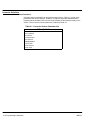
Table of Contents
Section 1
Quick Start Guide . . . . . . . . . . . . . . . . . . . . . . . . . . . . . . . . . . . . . . . . . . . . . . . . . . . . . . . . . . . . . . . . . . . . . . . . . . . . . . . . .
1-1
Overview . . . . . . . . . . . . . . . . . . . . . . . . . . . . . . . . . . . . . . . . . . . . . . . . . . . . . . . . . . . . . . . . . . . . . . . . . . . . . . . . . . . . .
1-1
Quick Start Checklist . . . . . . . . . . . . . . . . . . . . . . . . . . . . . . . . . . . . . . . . . . . . . . . . . . . . . . . . . . . . . . . . . . . . . . .
1-1
Quick Start Procedure . . . . . . . . . . . . . . . . . . . . . . . . . . . . . . . . . . . . . . . . . . . . . . . . . . . . . . . . . . . . . . . . . . . . . .
1-2
Section 2
General Information . . . . . . . . . . . . . . . . . . . . . . . . . . . . . . . . . . . . . . . . . . . . . . . . . . . . . . . . . . . . . . . . . . . . . . . . . . . . . . .
2-1
Overview . . . . . . . . . . . . . . . . . . . . . . . . . . . . . . . . . . . . . . . . . . . . . . . . . . . . . . . . . . . . . . . . . . . . . . . . . . . . . . . . . . . . .
2-1
Limited Warranty . . . . . . . . . . . . . . . . . . . . . . . . . . . . . . . . . . . . . . . . . . . . . . . . . . . . . . . . . . . . . . . . . . . . . . . . . . . . . . .
2-2
Safety Notice . . . . . . . . . . . . . . . . . . . . . . . . . . . . . . . . . . . . . . . . . . . . . . . . . . . . . . . . . . . . . . . . . . . . . . . . . . . . . . . . . .
2-3
Section 3
Receiving & Installation . . . . . . . . . . . . . . . . . . . . . . . . . . . . . . . . . . . . . . . . . . . . . . . . . . . . . . . . . . . . . . . . . . . . . . . . . . .
3-1
Receiving & Inspection . . . . . . . . . . . . . . . . . . . . . . . . . . . . . . . . . . . . . . . . . . . . . . . . . . . . . . . . . . . . . . . . . . . . . . . . .
3-1
Physical Location . . . . . . . . . . . . . . . . . . . . . . . . . . . . . . . . . . . . . . . . . . . . . . . . . . . . . . . . . . . . . . . . . . . . . . . . . . . . . .
3-1
Control Installation . . . . . . . . . . . . . . . . . . . . . . . . . . . . . . . . . . . . . . . . . . . . . . . . . . . . . . . . . . . . . . . . . . . . . . . . . . . . .
3-3
Through the Wall Mounting . . . . . . . . . . . . . . . . . . . . . . . . . . . . . . . . . . . . . . . . . . . . . . . . . . . . . . . . . . . . . . . . . . . . . .
3-3
Optional Remote Keypad Installation . . . . . . . . . . . . . . . . . . . . . . . . . . . . . . . . . . . . . . . . . . . . . . . . . . . . . . . . . . . . .
3-4
Electrical Installation . . . . . . . . . . . . . . . . . . . . . . . . . . . . . . . . . . . . . . . . . . . . . . . . . . . . . . . . . . . . . . . . . . . . . . . . . . .
3-5
Load Reactors . . . . . . . . . . . . . . . . . . . . . . . . . . . . . . . . . . . . . . . . . . . . . . . . . . . . . . . . . . . . . . . . . . . . . . . . . . . .
3-5
System Grounding . . . . . . . . . . . . . . . . . . . . . . . . . . . . . . . . . . . . . . . . . . . . . . . . . . . . . . . . . . . . . . . . . . . . . . . . .
3-5
Protection Devices . . . . . . . . . . . . . . . . . . . . . . . . . . . . . . . . . . . . . . . . . . . . . . . . . . . . . . . . . . . . . . . . . . . . . . . . .
3-8
Internal Fuses . . . . . . . . . . . . . . . . . . . . . . . . . . . . . . . . . . . . . . . . . . . . . . . . . . . . . . . . . . . . . . . . . . . . . . . . . . . . .
3-8
Wire Size and Protection Devices . . . . . . . . . . . . . . . . . . . . . . . . . . . . . . . . . . . . . . . . . . . . . . . . . . . . . . . . . . . .
3-9
Three Phase Input Power Connections . . . . . . . . . . . . . . . . . . . . . . . . . . . . . . . . . . . . . . . . . . . . . . . . . . . . . . .
3-10
Hardware Changes for Reduced Voltage Input . . . . . . . . . . . . . . . . . . . . . . . . . . . . . . . . . . . . . . . . . . . . . . . .
3-12
Motor Connections . . . . . . . . . . . . . . . . . . . . . . . . . . . . . . . . . . . . . . . . . . . . . . . . . . . . . . . . . . . . . . . . . . . . . . . . . . . . .
3-15
M-Contactor . . . . . . . . . . . . . . . . . . . . . . . . . . . . . . . . . . . . . . . . . . . . . . . . . . . . . . . . . . . . . . . . . . . . . . . . . . . . . . . . . . .
3-15
Encoder Installation . . . . . . . . . . . . . . . . . . . . . . . . . . . . . . . . . . . . . . . . . . . . . . . . . . . . . . . . . . . . . . . . . . . . . . . . . . . .
3-16
Buffered Encoder Output . . . . . . . . . . . . . . . . . . . . . . . . . . . . . . . . . . . . . . . . . . . . . . . . . . . . . . . . . . . . . . . . . . .
3-16
Home (Orient) Switch Input . . . . . . . . . . . . . . . . . . . . . . . . . . . . . . . . . . . . . . . . . . . . . . . . . . . . . . . . . . . . . . . . .
3-17
Control Board Jumpers . . . . . . . . . . . . . . . . . . . . . . . . . . . . . . . . . . . . . . . . . . . . . . . . . . . . . . . . . . . . . . . . . . . . .
3-18
Analog Inputs . . . . . . . . . . . . . . . . . . . . . . . . . . . . . . . . . . . . . . . . . . . . . . . . . . . . . . . . . . . . . . . . . . . . . . . . . . . . .
3-19
Analog Outputs . . . . . . . . . . . . . . . . . . . . . . . . . . . . . . . . . . . . . . . . . . . . . . . . . . . . . . . . . . . . . . . . . . . . . . . . . . . .
3-20
Continued on next page.
MN722
Table of Contents i
Control Circuit Connections . . . . . . . . . . . . . . . . . . . . . . . . . . . . . . . . . . . . . . . . . . . . . . . . . . . . . . . . . . . . . . . . . . . . .
3-21
Converting Control Board Connections . . . . . . . . . . . . . . . . . . . . . . . . . . . . . . . . . . . . . . . . . . . . . . . . . . . . . . .
3-21
Inverter Control Board Connections . . . . . . . . . . . . . . . . . . . . . . . . . . . . . . . . . . . . . . . . . . . . . . . . . . . . . . . . . .
3-22
Serial Mode . . . . . . . . . . . . . . . . . . . . . . . . . . . . . . . . . . . . . . . . . . . . . . . . . . . . . . . . . . . . . . . . . . . . . . . . . . . . . . .
3-22
Keypad Mode Connections . . . . . . . . . . . . . . . . . . . . . . . . . . . . . . . . . . . . . . . . . . . . . . . . . . . . . . . . . . . . . . . . .
3-23
Standard Run 3 Wire Mode Connections . . . . . . . . . . . . . . . . . . . . . . . . . . . . . . . . . . . . . . . . . . . . . . . . . . . . .
3-24
15 Speed 2-Wire Mode Connections . . . . . . . . . . . . . . . . . . . . . . . . . . . . . . . . . . . . . . . . . . . . . . . . . . . . . . . . .
3-25
3 Speed Analog 2 Wire Operating Mode . . . . . . . . . . . . . . . . . . . . . . . . . . . . . . . . . . . . . . . . . . . . . . . . . . . . . .
3-26
3 Speed Analog 3 Wire Operating Mode . . . . . . . . . . . . . . . . . . . . . . . . . . . . . . . . . . . . . . . . . . . . . . . . . . . . . .
3-27
Bipolar Speed and Torque Mode Connections . . . . . . . . . . . . . . . . . . . . . . . . . . . . . . . . . . . . . . . . . . . . . . . . .
3-28
Multiple Parameter Sets . . . . . . . . . . . . . . . . . . . . . . . . . . . . . . . . . . . . . . . . . . . . . . . . . . . . . . . . . . . . . . . . . . . .
3-29
Process Mode Connections . . . . . . . . . . . . . . . . . . . . . . . . . . . . . . . . . . . . . . . . . . . . . . . . . . . . . . . . . . . . . . . . .
3-30
Electronic Pot 2 Wire Operating Mode . . . . . . . . . . . . . . . . . . . . . . . . . . . . . . . . . . . . . . . . . . . . . . . . . . . . . . . .
3-31
Electronic Pot 3 Wire Control Mode . . . . . . . . . . . . . . . . . . . . . . . . . . . . . . . . . . . . . . . . . . . . . . . . . . . . . . . . . .
3-32
External Trip Input . . . . . . . . . . . . . . . . . . . . . . . . . . . . . . . . . . . . . . . . . . . . . . . . . . . . . . . . . . . . . . . . . . . . . . . . . . . . .
3-33
Opto-Isolated Inputs . . . . . . . . . . . . . . . . . . . . . . . . . . . . . . . . . . . . . . . . . . . . . . . . . . . . . . . . . . . . . . . . . . . . . . . . . . . .
3-33
Opto-Isolated Outputs . . . . . . . . . . . . . . . . . . . . . . . . . . . . . . . . . . . . . . . . . . . . . . . . . . . . . . . . . . . . . . . . . . . . . . . . . .
3-34
Pre-Operation Checklist . . . . . . . . . . . . . . . . . . . . . . . . . . . . . . . . . . . . . . . . . . . . . . . . . . . . . . . . . . . . . . . . . . . . . . . .
3-35
Power-Up Procedure . . . . . . . . . . . . . . . . . . . . . . . . . . . . . . . . . . . . . . . . . . . . . . . . . . . . . . . . . . . . . . . . . . . . . . . . . . .
3-36
Section 4
Programming and Operation . . . . . . . . . . . . . . . . . . . . . . . . . . . . . . . . . . . . . . . . . . . . . . . . . . . . . . . . . . . . . . . . . . . . . . .
4-1
Overview . . . . . . . . . . . . . . . . . . . . . . . . . . . . . . . . . . . . . . . . . . . . . . . . . . . . . . . . . . . . . . . . . . . . . . . . . . . . . . . . . . . . .
4-1
Baldor Keypad . . . . . . . . . . . . . . . . . . . . . . . . . . . . . . . . . . . . . . . . . . . . . . . . . . . . . . . . . . . . . . . . . . . . . . . . . . . . . . . . .
4-2
Display Mode . . . . . . . . . . . . . . . . . . . . . . . . . . . . . . . . . . . . . . . . . . . . . . . . . . . . . . . . . . . . . . . . . . . . . . . . . . . . . . . . . .
4-3
Adjusting Display Contrast . . . . . . . . . . . . . . . . . . . . . . . . . . . . . . . . . . . . . . . . . . . . . . . . . . . . . . . . . . . . . . . . . .
4-3
Display Mode Screens . . . . . . . . . . . . . . . . . . . . . . . . . . . . . . . . . . . . . . . . . . . . . . . . . . . . . . . . . . . . . . . . . . . . .
4-3
Display Screens & Diagnostic Information Access . . . . . . . . . . . . . . . . . . . . . . . . . . . . . . . . . . . . . . . . . . . . .
4-4
Fault Log Access . . . . . . . . . . . . . . . . . . . . . . . . . . . . . . . . . . . . . . . . . . . . . . . . . . . . . . . . . . . . . . . . . . . . . . . . . .
4-5
Program Mode . . . . . . . . . . . . . . . . . . . . . . . . . . . . . . . . . . . . . . . . . . . . . . . . . . . . . . . . . . . . . . . . . . . . . . . . . . . . . . . .
4-6
Parameter Blocks Access for Programming . . . . . . . . . . . . . . . . . . . . . . . . . . . . . . . . . . . . . . . . . . . . . . . . . . .
4-6
Changing Parameter Values when Security Code Not Used . . . . . . . . . . . . . . . . . . . . . . . . . . . . . . . . . . . .
4-7
Reset Parameters to Factory Settings . . . . . . . . . . . . . . . . . . . . . . . . . . . . . . . . . . . . . . . . . . . . . . . . . . . . . . . .
4-8
Initialize New Firmware . . . . . . . . . . . . . . . . . . . . . . . . . . . . . . . . . . . . . . . . . . . . . . . . . . . . . . . . . . . . . . . . . . . . .
4-9
Parameter Definitions . . . . . . . . . . . . . . . . . . . . . . . . . . . . . . . . . . . . . . . . . . . . . . . . . . . . . . . . . . . . . . . . . . . . . . . . . .
4-10
Converter Control Board Parameters . . . . . . . . . . . . . . . . . . . . . . . . . . . . . . . . . . . . . . . . . . . . . . . . . . . . . . . . .
4-10
Inverter Control Board Parameters . . . . . . . . . . . . . . . . . . . . . . . . . . . . . . . . . . . . . . . . . . . . . . . . . . . . . . . . . . .
4-12
Continued on next page.
ii Table of Contents
MN722
Section 5
Troubleshooting . . . . . . . . . . . . . . . . . . . . . . . . . . . . . . . . . . . . . . . . . . . . . . . . . . . . . . . . . . . . . . . . . . . . . . . . . . . . . . . . . .
5-1
No Keypad Display - Display Contrast Adjustment . . . . . . . . . . . . . . . . . . . . . . . . . . . . . . . . . . . . . . . . . . . . . . . . . .
5-1
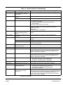
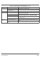
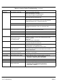
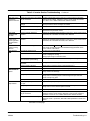
When a Fault is Displayed . . . . . . . . . . . . . . . . . . . . . . . . . . . . . . . . . . . . . . . . . . . . . . . . . . . . . . . . . . . . . . . . . . . . . .
5-1
How to Access the Fault Log . . . . . . . . . . . . . . . . . . . . . . . . . . . . . . . . . . . . . . . . . . . . . . . . . . . . . . . . . . . . . . . . . . . .
5-4
How to Clear the Fault Log . . . . . . . . . . . . . . . . . . . . . . . . . . . . . . . . . . . . . . . . . . . . . . . . . . . . . . . . . . . . . . . . . . . . . .
5-5
How to Access Diagnostic Information . . . . . . . . . . . . . . . . . . . . . . . . . . . . . . . . . . . . . . . . . . . . . . . . . . . . . . . . . . . .
5-6
Electrical Noise Considerations . . . . . . . . . . . . . . . . . . . . . . . . . . . . . . . . . . . . . . . . . . . . . . . . . . . . . . . . . . . . . . . . . .
5-15
Special Drive Situations . . . . . . . . . . . . . . . . . . . . . . . . . . . . . . . . . . . . . . . . . . . . . . . . . . . . . . . . . . . . . . . . . . . .
5-16
Control Enclosures . . . . . . . . . . . . . . . . . . . . . . . . . . . . . . . . . . . . . . . . . . . . . . . . . . . . . . . . . . . . . . . . . . . . . . . .
5-16
Special Motor Considerations . . . . . . . . . . . . . . . . . . . . . . . . . . . . . . . . . . . . . . . . . . . . . . . . . . . . . . . . . . . . . . .
5-16
Section 6
Manual Tuning the Series 22H Control . . . . . . . . . . . . . . . . . . . . . . . . . . . . . . . . . . . . . . . . . . . . . . . . . . . . . . . . . . . . . .
6-1
Manually Tuning the Control . . . . . . . . . . . . . . . . . . . . . . . . . . . . . . . . . . . . . . . . . . . . . . . . . . . . . . . . . . . . . . . . . . . . .
6-1
Motor Mag Amps Parameter . . . . . . . . . . . . . . . . . . . . . . . . . . . . . . . . . . . . . . . . . . . . . . . . . . . . . . . . . . . . . . . .
6-1
Slip Frequency Parameter . . . . . . . . . . . . . . . . . . . . . . . . . . . . . . . . . . . . . . . . . . . . . . . . . . . . . . . . . . . . . . . . . .
6-1
Current Prop Gain Parameter . . . . . . . . . . . . . . . . . . . . . . . . . . . . . . . . . . . . . . . . . . . . . . . . . . . . . . . . . . . . . . .
6-1
Current Int Gain Parameter . . . . . . . . . . . . . . . . . . . . . . . . . . . . . . . . . . . . . . . . . . . . . . . . . . . . . . . . . . . . . . . . .
6-2
Speed Prop Gain Parameter . . . . . . . . . . . . . . . . . . . . . . . . . . . . . . . . . . . . . . . . . . . . . . . . . . . . . . . . . . . . . . . .
6-2
Speed Int Gain Parameter . . . . . . . . . . . . . . . . . . . . . . . . . . . . . . . . . . . . . . . . . . . . . . . . . . . . . . . . . . . . . . . . . .
6-2
PI Controller . . . . . . . . . . . . . . . . . . . . . . . . . . . . . . . . . . . . . . . . . . . . . . . . . . . . . . . . . . . . . . . . . . . . . . . . . . . . . .
6-3
Continued on next page.
MN722
Table of Contents iii
Section 7
Specifications, Ratings & Dimensions . . . . . . . . . . . . . . . . . . . . . . . . . . . . . . . . . . . . . . . . . . . . . . . . . . . . . . . . . . . . . .
7-1
Specifications . . . . . . . . . . . . . . . . . . . . . . . . . . . . . . . . . . . . . . . . . . . . . . . . . . . . . . . . . . . . . . . . . . . . . . . . . . . . . . . . .
7-1
Operating Conditions . . . . . . . . . . . . . . . . . . . . . . . . . . . . . . . . . . . . . . . . . . . . . . . . . . . . . . . . . . . . . . . . . . . . . . .
7-1
Keypad Display . . . . . . . . . . . . . . . . . . . . . . . . . . . . . . . . . . . . . . . . . . . . . . . . . . . . . . . . . . . . . . . . . . . . . . . . . . .
7-1
Control Specifications . . . . . . . . . . . . . . . . . . . . . . . . . . . . . . . . . . . . . . . . . . . . . . . . . . . . . . . . . . . . . . . . . . . . . .
7-2
Differential Analog Input . . . . . . . . . . . . . . . . . . . . . . . . . . . . . . . . . . . . . . . . . . . . . . . . . . . . . . . . . . . . . . . . . . . .
7-2
Analog Outputs . . . . . . . . . . . . . . . . . . . . . . . . . . . . . . . . . . . . . . . . . . . . . . . . . . . . . . . . . . . . . . . . . . . . . . . . . . . .
7-2
Digital Inputs . . . . . . . . . . . . . . . . . . . . . . . . . . . . . . . . . . . . . . . . . . . . . . . . . . . . . . . . . . . . . . . . . . . . . . . . . . . . . .
7-3
Digital Outputs . . . . . . . . . . . . . . . . . . . . . . . . . . . . . . . . . . . . . . . . . . . . . . . . . . . . . . . . . . . . . . . . . . . . . . . . . . . .
7-3
Diagnostic Indications . . . . . . . . . . . . . . . . . . . . . . . . . . . . . . . . . . . . . . . . . . . . . . . . . . . . . . . . . . . . . . . . . . . . . .
7-3
Series 22H Vector Control Ratings . . . . . . . . . . . . . . . . . . . . . . . . . . . . . . . . . . . . . . . . . . . . . . . . . . . . . . . . . . . . . . .
7-4
Terminal Tightening Torque Specifications . . . . . . . . . . . . . . . . . . . . . . . . . . . . . . . . . . . . . . . . . . . . . . . . . . . . . . . . .
7-6
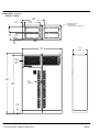
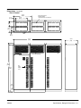
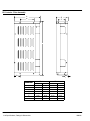
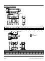
Dimensions . . . . . . . . . . . . . . . . . . . . . . . . . . . . . . . . . . . . . . . . . . . . . . . . . . . . . . . . . . . . . . . . . . . . . . . . . . . . . . . . . . .
7-7
Size C+ Control . . . . . . . . . . . . . . . . . . . . . . . . . . . . . . . . . . . . . . . . . . . . . . . . . . . . . . . . . . . . . . . . . . . . . . . . . . .
7-7
Size D+ Control . . . . . . . . . . . . . . . . . . . . . . . . . . . . . . . . . . . . . . . . . . . . . . . . . . . . . . . . . . . . . . . . . . . . . . . . . . .
7-8
Size D Control . . . . . . . . . . . . . . . . . . . . . . . . . . . . . . . . . . . . . . . . . . . . . . . . . . . . . . . . . . . . . . . . . . . . . . . . . . . .
7-9
Size E Control . . . . . . . . . . . . . . . . . . . . . . . . . . . . . . . . . . . . . . . . . . . . . . . . . . . . . . . . . . . . . . . . . . . . . . . . . . . . .
7-10
Size E Control − Through−Wall Mounting . . . . . . . . . . . . . . . . . . . . . . . . . . . . . . . . . . . . . . . . . . . . . . . . . . . . .
7-11
Size F Control . . . . . . . . . . . . . . . . . . . . . . . . . . . . . . . . . . . . . . . . . . . . . . . . . . . . . . . . . . . . . . . . . . . . . . . . . . . .
7-13
Size F Control − Through−Wall Mounting . . . . . . . . . . . . . . . . . . . . . . . . . . . . . . . . . . . . . . . . . . . . . . . . . . . . .
7-14
Size G+ Control . . . . . . . . . . . . . . . . . . . . . . . . . . . . . . . . . . . . . . . . . . . . . . . . . . . . . . . . . . . . . . . . . . . . . . . . . . .
7-16
Size H Control . . . . . . . . . . . . . . . . . . . . . . . . . . . . . . . . . . . . . . . . . . . . . . . . . . . . . . . . . . . . . . . . . . . . . . . . . . . .
7-17
EK Controls - Filter Assembly . . . . . . . . . . . . . . . . . . . . . . . . . . . . . . . . . . . . . . . . . . . . . . . . . . . . . . . . . . . . . . . . . . . .
7-18
EK Controls - Boost Regulators . . . . . . . . . . . . . . . . . . . . . . . . . . . . . . . . . . . . . . . . . . . . . . . . . . . . . . . . . . . . . . . . . .
7-19
Appendix A . . . . . . . . . . . . . . . . . . . . . . . . . . . . . . . . . . . . . . . . . . . . . . . . . . . . . . . . . . . . . . . . . . . . . . . . . . . . . . . . . . . . . . .
A-1
Converter Section Parameter Values . . . . . . . . . . . . . . . . . . . . . . . . . . . . . . . . . . . . . . . . . . . . . . . . . . . . . . . . . . . . .
A-1
Power Output Section Parameter Values . . . . . . . . . . . . . . . . . . . . . . . . . . . . . . . . . . . . . . . . . . . . . . . . . . . . . . . . . .
A-2
Appendix B . . . . . . . . . . . . . . . . . . . . . . . . . . . . . . . . . . . . . . . . . . . . . . . . . . . . . . . . . . . . . . . . . . . . . . . . . . . . . . . . . . . . . . .
B-1
Remote Keypad Mounting Template . . . . . . . . . . . . . . . . . . . . . . . . . . . . . . . . . . . . . . . . . . . . . . . . . . . . . . . . . . . . . .
B-2
iv Table of Contents
MN722
Section 1
Quick Start Guide
Overview
Quick Start Checklist
If you are an experienced user of Baldor controls, you are probably already familiar with
the keypad programming and keypad operation methods. If so, this quick start guide has
been prepared for you. This procedure will help get your system up and running in the
keypad mode quickly. This will allow motor and control operation to be verified. This
procedure assumes that the control and motor are correctly installed (see Section 3 for
procedures) and that you have an understanding of the keypad programming & operation
procedures. It is not necessary to wire the terminal strip to operate in the keypad mode, if
Level 2 Protection block parameters “External Trip” and “Local Enable INP” are set to off.
The quick start procedure is as follows:
1.
Read the Safety Notice and Precautions in section 2 of this manual.
2.
Mount the control. Refer to Section 3, “Physical Location” procedure.
3.
Connect AC power. Refer to Section 3, “AC Input Power Connections”.
4.
Connect the motor. Refer to Section 3, “Motor Connections”.
5.
Connect the encoder. Refer to Section 3, “Encoder Installation”.
Check of electrical items.
CAUTION: After completing the installation but before you apply power, be
sure to check the following items.
1.
Verify AC line voltage at source matches control rating.
2.
Inspect all power connections for accuracy, workmanship and torques as well
as compliance to codes.
3.
Verify control and motor are grounded to each other and the control is
connected to earth ground.
4.
Check all signal wiring for accuracy.
5.
Be certain all brake coils, contactors and relay coils have noise suppression.
This should be an R-C filter for AC coils and reverse polarity diodes for DC
coils. MOV type transient suppression is not adequate.
WARNING: Make sure that unexpected operation of the motor shaft during start
up will not cause injury to personnel or damage to equipment.
Check of Motor and Coupling
MN722
1.
Verify freedom of motion of motor shaft.
2.
Verify that motor coupling is tight without backlash.
2.
Verify the holding brakes if any, are properly adjusted to fully release and set to
the desired torque value.
Quick Start Guide 1-1
Section 1
General Information
Quick Start Procedure
Initial Conditions
Be sure the 22H control and motor are installed and wired according to the procedures in
Section 3 of this manual.
Become familiar with the keypad programming and keypad operation of the control as
described in Section 4 of this manual.
1.
Disconnect the load (including coupling or inertia wheels) from the motor shaft if
possible.
2.
Verify that all enable inputs to J1-8 are open.
3.
Turn power on. Be sure no errors are displayed.
4.
Set the Level 1 Input block, Operating Mode parameter to “KEYPAD”.
5.
Set the Level 2 Output Limits block, “OPERATING ZONE” parameter as
desired.
6.
Enter the following motor data in the Level 2 Motor Data block parameters:
Motor Voltage (Nameplate, VOLTS)
Motor Rated Amps (Nameplate, FLA)
Motor Rated Speed (Nameplate, RPM)
Motor Rated Frequency (Nameplate, HZ)
Motor Mag Amps (Nameplate, NLA)
Encoder Counts
7.
At the Level 2 Motor Data, go to CALC Presets and select YES (using the up
arrow key). Press ENTER and let the control calculate the preset values for the
parameters that are required for control operation.
8.
Disconnect the motor from the load (including coupling or inertia wheels). If the
load can not be disconnected, refer to Section 6 and manually tune the control.
After manual tuning, perform steps 10, 11, 15, 16 and 17.
WARNING: The motor shaft will rotate during this procedure. Be certain that
unexpected motor shaft movement will not cause injury to
personnel or damage to equipment.
9. At the Level 2 Autotune block, perform the following tests:
CMD OFFSET TRIM
CUR LOOP COMP
STATOR R1
FLUX CUR SETTING
FEEDBACK TESTS
SLIP FREQ TEST
10. Set the Level 2 Output Limits block, “MIN OUTPUT SPEED” parameter.
11
Set the Level 2 Output Limits block, “MAX OUTPUT SPEED” parameter.
12. Remove all power from the control.
13. Couple the motor to its load.
14. Turn power on. Be sure no errors are displayed.
15. Go to Level 2 Autotune block, and perform the SPD CNTRLR CALC test.
16. Run the drive from the keypad using one of the following: the arrow keys for
direct speed control, keypad entered speed or the JOG mode.
17. Select and program additional parameters to suit your application.
The control is now ready for use the in keypad mode. If a different operating mode is
desired, refer to Section 3 for control connection diagrams and Section 4 Programming
and Operation.
1-2 Quick Start Guide
MN722
Section 2
General Information
Overview
The Baldor Series 22H Line Regen Vector Control provides full motoring and line
regeneration to the AC power mains with a near unity power factor. The control uses
PWM controlled by IGBT power transistors in both the converter and inverter sections of
the control to provide 3 phase power to the motor and Regen power to the line. Flux
vector technology (sometimes referred to as Field Oriented Control) is a closed loop
control scheme that adjusts the frequency and phase of voltage and current applied to a
three phase induction motor. The vector control separates the motor current into it’s flux
and torque producing components. These components are independently adjusted and
vectorially added to maintain a 90 degree relationship between them. This produces
maximum torque from base speed down to and including zero speed. Above base
speed, the flux component is reduced for constant horsepower operation. In addition to
the current, the electrical frequency must also be controlled. The frequency of the
voltage applied to the motor is calculated from the slip frequency and the mechanical
speed of the rotor. This provides instantaneous adjustment of the voltage and current
phasing in response to speed and position feedback from an encoder mounted on the
motors’ shaft.
The Line Regen vector control provides several advantages over non-regenerative
drives:
Regenerated energy from the motor is returned to the power source. The
control can provide regenerated energy absorption up to it’s full rating on a
continuous basis.
Input current is controlled to be a near unity power factor at rated load.
Line harmonic distortion is reduced.
DC Bus voltage is always controlled. Therefore, line voltage transients do not
affect the output voltage to the motor.
The Baldor Series 22H control may be used in many different applications. It may be
programmed by the user to operate in different operating zones. It can also be
configured to operate in a number of modes depending upon the application
requirements and user preference.
It is the responsibility of the user to determine the optimum operating zone and mode to
interface the control to the application. These choices are made with the keypad as
explained in the programming section of this manual.
MN722
General Information 2-1
Limited Warranty
For a period of two (2) years from the date of original purchase, BALDOR will
repair or replace without charge controls and accessories which our
examination proves to be defective in material or workmanship. This
warranty is valid if the unit has not been tampered with by unauthorized
persons, misused, abused, or improperly installed and has been used in
accordance with the instructions and/or ratings supplied. This warranty is in
lieu of any other warranty or guarantee expressed or implied. BALDOR
shall not be held responsible for any expense (including installation and
removal), inconvenience, or consequential damage, including injury to any
person or property caused by items of our manufacture or sale. (Some
states do not allow exclusion or limitation of incidental or consequential
damages, so the above exclusion may not apply.) In any event, BALDOR’s
total liability, under all circumstances, shall not exceed the full purchase
price of the control. Claims for purchase price refunds, repairs, or
replacements must be referred to BALDOR with all pertinent data as to the
defect, the date purchased, the task performed by the control, and the
problem encountered. No liability is assumed for expendable items such as
fuses.
Goods may be returned only with written notification including a BALDOR
Return Authorization Number and any return shipments must be prepaid.
2-2 General Information
MN722
Safety Notice
This equipment contains voltages that may be as high as 1000 volts! Electrical shock
can cause serious or fatal injury. Only qualified personnel should attempt the start−up
procedure or troubleshoot this equipment.
This equipment may be connected to other machines that have rotating parts or parts
that are driven by this equipment. Improper use can cause serious or fatal injury. Only
qualified personnel should attempt the start−up procedure or troubleshoot this equipment.
PRECAUTIONS
WARNING: Do not touch any circuit board, power device or electrical
connection before you first ensure that power has been
disconnected and there is no high voltage present from this
equipment or other equipment to which it is connected. Electrical
shock can cause serious or fatal injury. Only qualified personnel
should attempt the start−up procedure or troubleshoot this
equipment.
WARNING: Be sure that you are completely familiar with the safe operation of
this equipment. This equipment may be connected to other
machines that have rotating parts or parts that are controlled by
this equipment. Improper use can cause serious or fatal injury.
Only qualified personnel should attempt the start−up procedure or
troubleshoot this equipment.
WARNING: This unit has an automatic restart feature that will start the motor
whenever input power is applied and a RUN (FWD or REV)
command is issued. If an automatic restart of the motor could
cause injury to personnel, the automatic restart feature should be
disabled by changing the Level 2 Miscellaneous block, Restart
Auto/Man parameter to Manual.
WARNING: Be sure the system is properly grounded before applying power.
Do not apply AC power before you ensure that all grounding
instructions have been followed. Electrical shock can cause
serious or fatal injury.
WARNING: Do not remove cover for at least five (5) minutes after AC power is
disconnected to allow capacitors to discharge. Dangerous voltages
are present inside the equipment. Electrical shock can cause
serious or fatal injury.
WARNING: Improper operation of control may cause violent motion of the
motor shaft and driven equipment. Be certain that unexpected
motor shaft movement will not cause injury to personnel or damage
to equipment. Certain failure modes of the control can produce
peak torque of several times the rated motor torque.
WARNING: Motor circuit may have high voltage present whenever AC power is
applied, even when motor is not rotating. Electrical shock can
cause serious or fatal injury.
WARNING: The motor shaft will rotate during the autotune procedure. Be
certain that unexpected motor shaft movement will not cause injury
to personnel or damage to equipment.
Continued on next page
MN722
General Information 2-3
Section 1
General Information
2-4 General Information
Caution:
Suitable for use on a circuit capable of delivering not more than the
RMS symmetrical short circuit amperes listed here at rated voltage.
Horsepower RMS Symmetrical Amperes
1−50
5,000
51−200
10,000
201−400
18,000
401−600
30,000
601−900
42,000
Caution:
Disconnect motor leads (T1, T2 and T3) from control before you
perform a “Megger” test on the motor. Failure to disconnect motor
from the control will result in extensive damage to the control. The
control is tested at the factory for high voltage / leakage resistance
as part of Underwriter Laboratory requirements.
Caution:
Do not supply any power to the External Trip (motor thermostat)
leads at J1-16 and 17. Power on these leads can damage the
control. Use a dry contact type that requires no external power to
operate.
Caution:
Do not connect AC power to the Motor terminals T1, T2 and T3.
Connecting AC power to these terminals may result in damage to
the control.
Caution:
Baldor recommends not using “Grounded Leg Delta” transformer
power leads that may create ground loops and degrade system
performance. Instead, we recommend using a four wire Wye.
Caution:
Do not use power factor correction capacitors at the input power
lines to the 22H Line Regen control. Installing power factor
correction capacitors may damage the control.
MN722
Section 3
Receiving & Installation
Receiving & Inspection
Physical Location
The Series 22H Vector Control is thoroughly tested at the factory and carefully packaged
for shipment. When you receive your control, there are several things you should do
immediately.
1.
Observe the condition of the shipping container and report any damage
immediately to the commercial carrier that delivered your control.
2.
Verify that the part number of the control you received is the same as the part
number listed on your purchase order.
3.
If the control is to be stored for several weeks before use, be sure that it is
stored in a location that conforms to published storage specifications. (Refer to
Section 7 of this manual).
The location of the 22H is important. It should be installed in an area that is protected
from direct sunlight, corrosives, harmful gases or liquids, dust, metallic particles, and
vibration. Exposure to these elements can reduce the operating life and degrade
performance of the control.
Several other factors should be carefully evaluated when selecting a location for
installation:
1.
For effective cooling and maintenance, the control should be mounted vertically
on a flat, smooth, non-flammable vertical surface. Size G+ are floor standing
NEMA 1 enclosures.
2.
At least two inches clearance must be provided on all sides for air flow.
3.
Front access must be provided to allow the control cover to be opened or
removed for service and to allow viewing of the Keypad Display. (The keypad
may optionally be remote mounted up to 100 feet from the control.)
Controls installed in a floor mounted enclosure must be positioned with
clearance to open the enclosure door. This clearance will also provide
sufficient air space for cooling.
4.
Altitude derating. Up to 3300 feet (1000 meters) no derating required. Above
3300 ft, derate the continuous and peak output current by 2% for each 1000 ft.
5.
Temperature derating. Up to 40°C no derating required. Above 40°C, derate
the continuous and peak output current by 2% per °C. Maximum ambient is
55°C.
6.
50Hz Operation derating. For operation on 50Hz input power, derate the
continuous and peak output current by 15%.
7.
Shock Mounting. The control is designed to withstand 0.5G at 10 to 60 Hz
shock during normal operation.
Shock Mounting
If the control will be subjected to levels of shock greater than 1G or vibration greater than
0.5G at 10 to 60Hz, the control should be shock mounted. Excessive vibration within the
control could cause internal connections to loosen and cause component failure or
electrical shock hazard.
MN722
Receiving & Installation 3-1
Section 1
General Information
,
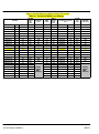
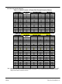
Table 3-1 lists the Watts Loss ratings for Series 22H controls.
Table 3-1 Series 22H Watts Loss Ratings.
CONTROL
STD PWM
CONV &
INV
Losses
QUIET PWM
CONV & INV
Losses
CONTROL
FIXED
Losses
BOOST
REG Loss
At Full
Load
Line Reactor Loss At Full
Load
STD PWM
Total
Losses
QUIET PWM
Total Losses
MODEL No.
SIZE
INPUT VAC
(Watts)
(Watts)
(Watts)
(Watts)
Cat. No.
(Watts)
(Watts)
(Watts)
ZD22H210−EL
C+
230
268
315
102
80
LRAC03501
49
499
546
ZD22H215−EL
C+
230
397
311
102
109
LRAC04501
54
662
576
ZD22H220−EL
C+
230
527
458
102
136
LRAC05501
64
829
760
ZD22H225−EL
C+
230
690
611
102
137
LRAC08001
82
1011
932
ZD22H230−EL
D+
230
571
768
170
164
LRAC08001
82
987
1184
ZD22H240−EL
D+
230
1095
942
170
187
LRAC10001
94
1546
1393
ZD22H250−EL
D+
230
1437
1286
170
225
LRAC13001
108
1940
1789
ZD22H410−EL
C+
460
240
326
102
80
LRAC01802
43
465
551
ZD22H415−EL
C+
460
336
259
102
86
LRAC02502
52
576
499
ZD22H420−EL
C+
460
432
379
102
110
LRAC03502
54
698
645
ZD22H425−EL
D+
460
544
504
102
134
LRAC03502
54
834
794
ZD22H430−EL
D+
460
640
740
170
158
LRAC04502
62
1030
1130
ZD22H440−EL
D+
460
880
738
170
228
LRAC05502
67
1345
1203
ZD22H450−EL
D+
460
1040
1023
170
217
LRAC08002
86
1513
1496
ZD22H460−EK
D+
460
1280
1236
100
299
LRAC08002
86
1765
1721
ZD22H475−EK
E
460
2400
2322
153
395
LRAC10002
84
3032
2954
ZD22H4100−EK
E
460
3000
2928
153
420
LRAC13002
180
3753
3681
ZD22H4150−EK
F
460
3610
191
750
LRAC20002
168
4719
ZD22H4200−EK
F
460
4750
191
850
LRAC25002
231
6022
ZD22H4250−EL
G+
460
6200
1000
900
LRAC32002
264
8364
ZD22H4300−EL
G+
460
8140
1000
1620
LRAC40002
333
11093
ZD22H4450−EL
G+
460
8400
1000
1650
LRAC50002
340
11390
ZD22H4400−EL
G+
460
10560
1000
1750
LRAC50002
340
13650
ZD22H4450−EL
G+
460
11880
1000
1850
LRAC60002
414
15144
3-2 Receiving & Installation
CONTROL
RATINGS
NOT
AVAILABLE
CONTROL
RATINGS
NOT
AVAILABLE
MN722
Section 1
General Information
Control Installation
The control must be securely fastened to the mounting surface. Use the four (4)
mounting holes to fasten the control to the mounting surface or enclosure.
Through the Wall Mounting Control sizes E and F are designed for panel or through the wall installation. To mount a
control through the wall, an optional Through the Wall mounting kit must be purchased.
These kits are:
Description
Kit No.
V0083991 Size E control Through the Wall mounting kit.
V0084001 Size F control Through the Wall mounting kit.
Procedure:
MN722
1.
Refer to Section 7 of this manual for drawings and dimensions of the Through
the Wall mounting kits. Use the information contained in these drawings to
layout the appropriate size hole on your enclosure and wall.
2.
Cut the holes in your enclosure and wall.
3.
Locate and drill holes for mounting hardware as shown in the drawings.
4.
Cut foam tape and apply to perimeter of opening as shown.
5.
Secure the four (4) brackets to the exterior of the panel with the hardware
provided.
6.
Secure the control to the panel using the hardware provided.
Receiving & Installation 3-3
Section 1
General Information
Optional Remote Keypad Installation The keypad may be remotely mounted using the optional Baldor keypad
extension cable. The keypad assembly (white - DC00005A-01; grey - DC00005A-02)
comes complete with the screws and gasket required to mount it to an enclosure. When
the keypad is properly mounted to a NEMA Type 4X indoor enclosure, it retains the Type
4X indoor rating.
Mounting Instructions:
Mounting Instructions:
3-4 Receiving & Installation
Tools Required:
•
Center punch, tap handle, screwdrivers (Phillips and straight) and crescent
wrench.
•
8-32 tap and #29 drill bit (for tapped mounting holes) or #19 drill (for clearance
mounting holes).
•
1-1/4″ standard knockout punch (1-11/16″ nominal diameter).
•
RTV sealant.
•
(4) 8-32 nuts and lock washers.
•
Extended 8-32 screws (socket fillister) are required if the mounting surface is
thicker than 12 gauge and is not tapped (clearance mounting holes).
•
Remote keypad mounting template. A tear out copy is provided at the end of
this manual for your convenience.
For tapped mounting holes
1. Locate a flat 4″ wide x 5.5″ minimum high mounting surface. Material should
be sufficient thickness (14 gauge minimum).
2. Place the template on the mounting surface or mark the holes as shown.
3. Accurately center punch the 4 mounting holes (marked A) and the large
knockout (marked B).
4. Drill four #29 mounting holes (A). Thread each hole using an 8-32 tap.
5. Locate the 1-1/4″ knockout center (B) and punch using the manufacturers
instructions.
6. Debur knockout and mounting holes making sure the panel stays clean and flat.
7. Apply RTV to the 4 holes marked (A).
8. Assemble the keypad to the panel. Use 8−32 screws, nuts and lock washers.
9. From the inside of the panel, apply RTV over each of the four mounting screws
and nuts. Cover a 3/4″ area around each screw while making sure to completely
encapsulate the nut and washer.
For clearance mounting holes
1. Locate a flat 4″ wide x 5.5″ minimum high mounting surface. Material should
be sufficient thickness (14 gauge minimum).
2. Place the template on the mounting surface or mark the holes as shown on the
template.
3. Accurately center punch the 4 mounting holes (marked A) and the large
knockout (marked B).
4. Drill four #19 clearance holes (A).
5. Locate the 1-1/4″ knockout center (B) and punch using the manufacturers
instructions.
6. Debur knockout and mounting holes making sure the panel stays clean and flat.
7. Apply RTV to the 4 holes marked (A).
8. Assemble the keypad to the panel. Use 8−32 screws, nuts and lock washers.
9. From the inside of the panel, apply RTV over each of the four mounting screws
and nuts. Cover a 3/4″ area around each screw while making sure to completely
encapsulate the nut and washer.
MN722
Section 1
General Information
Electrical Installation
Interconnection wiring is required between the motor control, AC power source, motor,
host control and any operator interface stations. Use only UL (cUL) listed closed loop
connectors that are of appropriate size for wire gauge being used. Connectors are to be
installed using crimp tool specified by the manufacturer of the connector. Only Class 1
wiring should be used.
Baldor Series 22H controls feature UL approved adjustable motor overload protection
suitable for motors rated at no less than 50% of the output rating of the control. Other
governing agencies such as NEC may require separate over−current protection. The
installer of this equipment is responsible for complying with the National Electric Code
and any applicable local codes which govern such practices as wiring protection,
grounding, disconnects and other current protection.
Line reactors may be used at the control output to the motor. When used this way, they are
called Load Reactors. Load reactors serve several functions that include:
Load Reactors
Protect the control from a short circuit at the motor.
Limit the rate of rise of motor surge currents.
Slowing the rate of change of power the control delivers to the motor.
Load reactors should be installed as close to the control as possible. Select the load
reactor that matches the full load amperes (FLA) stated on the nameplate of the motor
you are using.
Baldor Controls are designed to be powered from standard three phase lines that are
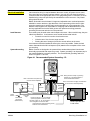
electrically symmetrical with respect to ground. System grounding is an important step in
the overall installation to prevent problems. The recommended grounding method is
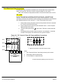
shown in Figures 3-1 and 3-2.
System Grounding
Figure 3-1 Recommended System Grounding − EL
JOG
LOCAL
FWD
DISP
REV
SHIFT
STOP
RESET
PROG
ENTER
Series H
Note: A line reactor is required and
must be ordered separately.
AC Main
Supply
L1 L2 L3
T1 T2 T3
Note: Wiring shown for clarity of grounding
method only. Not representative of
actual terminal block location.
Note: A load reactor is highly recommended
and must be ordered separately.
L1
Line
Reactor
L2
Optional
Load
Reactor
L3
Earth
Safety
Ground
Driven Earth
Ground Rod
(Plant Ground)
MN722
Four Wire
“Wye”
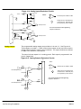
Route all 4 wires L1, L2, L3 and Earth
(Ground) together in conduit or cable.
Route all 4 wires T1, T2, T3 and Motor
Ground together in conduit or cable.
Connect all wires (including motor ground)
inside the motor terminal box.
Ground per NEC and
Local codes.
Receiving & Installation 3-5
Section 1
General Information
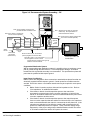
Figure 3-2 Recommended System Grounding − EK
Note: A boost regulator is required and
provided with each model EK control.
Note: A line reactor is required and
must be ordered separately.
AC Main
Supply
L1
L2
JOG
LOCAL
FWD
DISP
REV
SHIFT
STOP
RESET
PROG
ENTER
Series H
Note: Wiring shown for clarity of grounding
method only. Not representative of
actual terminal block location.
L1 L2 L3
T1 T2 T3
Note: A load reactor is highly recommended
and must be ordered separately.
Line
Reactor
Boost
Regulator
Optional
Load
Reactor
L3
Earth
Safety
Ground
Driven Earth
Ground Rod
(Plant Ground)
Four Wire
“Wye”
Route all 4 wires L1, L2, L3 and Earth
(Ground) together in conduit or cable.
Route all 4 wires T1, T2, T3 and Motor
Ground together in conduit or cable.
Ground per NEC and
Local codes.
Connect all wires (including motor ground)
inside the motor terminal box.
Ungrounded Distribution System
With an ungrounded power distribution system it is possible to have a continuous current
path to ground through the MOV devices. To avoid equipment damage, an Isolation
transformer with a grounded secondary is recommended. This provides three phase AC
power that is symmetrical with respect ground.
Input Power Conditioning
Baldor controls are designed for direct connection to standard three phase lines that are
electrically symmetrical with respect to ground. Certain power line conditions must be
avoided. An AC line reactor or an isolation transformer may be required for some power
conditions.
3-6 Receiving & Installation
Baldor Series H controls require a minimum line impedance of 3%. Refer to
“Line Impedance” for additional information.
If the feeder or branch circuit that provides power to the control has
permanently connected power factor correction capacitors, an input AC line
reactor or an isolation transformer must be connected between the power factor
correction capacitors and the control.
If the feeder or branch circuit that provides power to the control has power
factor correction capacitors that are switched on line and off line, the capacitors
must not be switched while the control is connected to the AC power line. If the
capacitors are switched on line while the control is still connected to the AC
power line, additional protection is required. TVSS (Transient Voltage Surge
Suppressor) of the proper rating must be installed between the AC line reactor
or an isolation transformer and the AC input to the control.
MN722
Section 1
General Information
Current Requirements
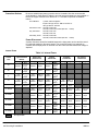
The input current for each control is given in Table 3-2 and the short circuit requirements
are given in Table 3-3. The control may be damaged if input current exceeds ratings.
Table 3-2 Input Current Requirements
230VAC
Catalog Numbers
460VAC
Input
Amps
Catalog Numbers
Input
Amps
ZD22H210−EL
24
ZD22H410−EL
13
ZD22H215−EL
36
ZD22H415−EK
18
ZD22H220−EL
47
ZD22H420−EL
23
ZD22H225−EL
58
ZD22H425−EL
29
ZD22H230−EL
68
ZD22H430−EL
34
ZD22H240−EL
90
ZD22H440−EL
47
ZD22H250−EL
111
ZD22H450−EL
56
ZD22H460−EK
ZD22H475−EK
ZD22H4100−EK
ZD22H4150−EK
ZD22H4200−EK
ZD22H4250−EL
68
85
107
162
213
264
ZD22H4300−EL
315
ZD22H4350−EL
357
ZD22H4400−EL
408
ZD22H4450−EL
459
Table 3-3 Short Circuit Current Ratings
230VAC
Catalog Numbers
MN722
460VAC
Short Circuit
Amps
Catalog Numbers
Short Circuit
Amps
ZD22H210−EL
240
ZD22H410−EL
130
ZD22H215−EL
360
ZD22H415−EK
180
ZD22H220−EL
470
ZD22H420−EL
230
ZD22H225−EL
580
ZD22H425−EL
290
ZD22H230−EL
680
ZD22H430−EL
340
ZD22H240−EL
890
ZD22H440−EL
470
ZD22H250−EL
1110
ZD22H450−EL
550
ZD22H460−EK
ZD22H475−EK
ZD22H4100−EK
ZD22H4150−EK
ZD22H4200−EK
ZD22H4250−EL
680
850
1060
1620
2130
2640
ZD22H4300−EL
3150
ZD22H4350−EL
3570
ZD22H4400−EL
4080
ZD22H4450−EL
4590
Receiving & Installation 3-7
Section 1
General Information
Protection Devices
Be sure a suitable input power protection device is installed. Use the recommended
circuit breaker or fuses listed in Table 3-5 and 3-6. Input and output wire size is based on
the use of copper conductor wire rated at 75 °C. The table is specified for NEMA B
motors.
Circuit Breaker:
3 phase, thermal magnetic.
Equal to GE type THQ or TEB for 230 VAC or
GE type TED for 460 VAC
Fast Action Fuses:
230 VAC, Buss KTN
460 VAC, Buss KTS to 600A (KTU 601 - 1200A)
Very Fast Action:
230 VAC, Buss JJN
460 VAC, Buss JJS
Time Delay Fuses:
230 VAC, Buss FRN
460 VAC, Buss FRS to 600A (KLU 601 - 1200A)
Power Disconnect
A power disconnect should be installed between the input power service and the control
for a fail safe method to disconnect power. The control will remain in a powered-up
condition until all input power is removed from the control and the internal bus voltage is
depleted.
Internal Fuses
Table 3-4 Internal Fuses
Control
S e
Size
Zero Crossing
(Input Interface
Board)
Rating
Type
FLQ3/ A
10
3/
10 or
500VAC
Equiv.
FLQ3/ A
10
3/
10 or
500VAC
Equiv.
FLQ3/ A
10
3/
10 or
500VAC
Equiv.
FLQ3/ A
10
3/
10 or
500VAC
Equiv.
3A
ATM-3
600VAC or Equiv.
Filter Fuses
(Filter Board)
Control
Transformer
Rating
Type
Rating
5A
500VAC
FNQ-5 or
Equiv.
3.2A
250VAC
5A
500VAC
FNQ-5 or
Equiv.
3.2A
250VAC
10A
600VAC
KTK-10
or Equiv.
3.2A
250VAC
10A
600VAC
KTK-10
or Equiv.
3.2A
250VAC
3A
500VAC
KTK-3 or
Equiv.
3A
600VAC
G+ 250HP
50A
600VAC
JJS or
Equiv.
31/2 A
500VAC
G+300HP
50A
600VAC
JJS or
Equiv.
31/2 A
500VAC
G+350HP
60A
600VAC
JJS or
Equiv.
31/2 A
500VAC
G+400HP
70A
600VAC
JJS or
Equiv.
31/2 A
500VAC
G+450HP
70A
600VAC
JJS or
Equiv.
31/2 A
500VAC
C+
D+
D
E
F
Type
MDA3 2/10 or
Equiv.
MDA3 2/10 or
Equiv.
MDA3 2/10 or
Equiv.
MDA3 2/10 or
Equiv.
KTK-3 or
Equiv.
FNQ31/2 or
Equiv.
FNQ31/2 or
Equiv.
FNQ31/2 or
Equiv.
FNQ31/2 or
Equiv.
FNQ31/2 or
Equiv.
Soft Start
Transformer
Rating
Type
1/ A
2
250VAC
ABC 1/2
or Equiv.
3A
600VAC
KTK-3 or
Equiv.
4A
500VAC
Fan Control
Transformer
Rating
Type
FNQ-4 or
Equiv.
3A
500VAC
FNQ-3 or
Equiv.
4A
500VAC
FNQ-4 or
Equiv.
3A
500VAC
FNQ-3 or
Equiv.
4A
500VAC
FNQ-4 or
Equiv.
3A
500VAC
FNQ-3 or
Equiv.
4A
500VAC
FNQ-4 or
Equiv.
3A
500VAC
FNQ-3 or
Equiv.
4A
500VAC
FNQ-4 or
Equiv.
3A
500VAC
FNQ-3 or
Equiv.
Not applicable.
3-8 Receiving & Installation
MN722
Section 1
General Information
Wire Size and Protection Devices
Table 3-5 230VAC Controls (3 Phase) Wire Size and Protection Devices
Control Rating
Amps
HP
3
0.75
4
1
7
2
10
3
16
5
22
7.5
28
10
42
15
54
20
68
25
80
30
104
40
130
50
145
60
192
75
Input Breaker
(Amps)
7
7
15
15
20
30
40
60
70
90
100
150
175
200
250
Input Fuse (Amps)
Fast Acting
Time Delay
5
4
6
5
12
9
15
12
25
20
35
30
45
35
70
60
80
70
100
90
125
110
175
150
200
175
225
200
300
250
Wire Gauge
AWG
mm2
14
2.5
14
2.5
14
2.5
14
2.5
12
3.31
10
5.26
8
8.37
6
13.3
6
13.3
4
21.2
3
26.7
1
42.4
1/0
53.5
2/0
67.4
4/0
107.0
Table 3-6 460VAC Controls (3 Phase) Wire Size and Protection Devices
Control Rating
Amps
HP
2
0.75
2
1
4
2
5
3
8
5
11
7.5
14
10
21
15
27
20
34
25
40
30
52
40
65
50
77
60
96
75
124
100
156
125
180
150
240
200
302
250
361
300
414
350
477
400
515
450
590
500
Input
p Breaker
(A
(Amps)
)
3
3
7
7
15
15
20
30
40
50
50
70
90
100
125
175
200
225
300
400
450
500
600
650
750
Input Fuse (Amps)
Fast Acting
Time Delay
2
2
3
2.5
5
4.5
8
6.3
12
10
17.5
15
20
17.5
30
25
40
35
50
45
60
50
80
70
100
90
125
100
150
125
200
175
250
200
300
250
350
300
450
400
600
450
650
500
750
600
800
700
900
800
Wire Gauge
AWG
mm2
14
2.5
14
2.5
14
2.5
14
2.5
14
2.5
14
2.5
12
3.31
10
5.26
10
5.26
8
8.37
8
8.37
6
13.3
4
21.2
3
26.7
2
33.6
1/0
53.5
2/0
67.4
3/0
85.0
(2) 2/0
(2) 67.4
(2) 4/0
(2) 107.0
(3) 2/0
(3) 67.4
(3) 3/0
(3) 85.0
(3) 4/0
(3) 107.0
(3) 250MCM (3) 127.0
(3) 300MCM (3) 152.0
Note: All wire sizes are based on 75°C copper wire. Higher temperature smaller gauge wire may be used per NEC
and local codes. Recommended fuses/breakers are based on 40°C ambient, maximum continuous control
output current and no harmonic current.
MN722
Receiving & Installation 3-9
Section 1
General Information
Three Phase Input Power Connections
AC power and motor connections are different for controls that have a model number
suffix of “EL” and “EK”. Be sure to use the correct procedure for your control.
Note: “EK” Controls are input phase sensitive. Be sure all connections are correct.
“EL” suffix
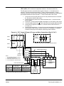
The AC power and motor connections are shown in Figure 3-3. Overloads are not
required. The 22H control has an electronic I2t motor overload protection. If motor
overloads are desired, they should be sized according to the manufacturers specifications
and installed between the motor and the T1, T2 and T3 terminals of the control.
1.
Connect the incoming AC power wires from the protection devices to terminals
A1, B1 and C1 at the 3% line reactor.
2.
Connect A2, B2 and C2 3% line reactor terminals to the L1, L2 and L3 power
input terminals of the control.
3.
* Connect earth ground to the “ ” of the control. Be sure to comply with local
codes.
*
Grounding by using conduit or panel connection is not adequate. A separate
conductor of the proper size must be used as a ground conductor.
Figure 3-3 “EL” Control 3 Phase AC Power and Motor Connections
L1
L2
L3
L1
Earth
Note 1
L2
L3
Alternate *
Fuse
Connection
* Circuit
Breaker
Note 1
Note 2
Note 3
Note 2
A1
B1
C1
A2
B2
C2
A1
B1
C1
Line
Reactor
L1
L2
* Optional components not provided with 22H Control.
L3
Baldor
Series 22HXXX-EL
Control
Notes:
1.
See “Protective Devices” described previously in this section.
2.
Shield wires inside a metal conduit.
3.
3% Line Reactor is required at input.
See Recommended Tightening Torques in Section 7.
3-10 Receiving & Installation
MN722
Section 1
General Information
“EK” suffix (“EK” Controls are input phase sensitive. Check all connections).
The AC power and motor connections are shown in Figure 3-4. Overloads are not
required. The 22H control has an electronic I2t motor overload protection. If motor
overloads are desired, they should be sized according to the manufacturers specifications
and installed between the motor and the T1, T2 and T3 terminals of the control.
1.
Connect the incoming AC power wires from the protection devices to terminals
A1, B1 and C1 of the 3% line reactor.
Connect A2, B2 and C2 3% line reactor terminals to the L1, L2 and L3 of the
boost regulator.
Connect X1, X2 and X3 boost regulator terminals to X1, X2 and X3 of the control.
* Connect earth ground to the “ ” of the control. Be sure to comply with local codes.
Connect boost regulator terminals L1A, L2A and L3A to Filter terminals J1-1,
J1-2 and J1-3.
Connect filter terminals J2-1, J2-2 and J2-3 to control terminals L1A, L2A and L3A.
Grounding by using conduit or panel connection is not adequate. A separate
conductor of the proper size must be used as a ground conductor.
2.
3.
4.
5.
6.
*
Figure 3-4 “EK” Control 3 Phase AC Power and Motor Connections (Size D, E & F)
L1
Note 1
L2
L3
Earth
L1
L2
L3
Alternate *
Fuse
Connection
* Circuit
Breaker
Note 1
Note 2
A1
Note 3
Note 2
B1
C1
A1
C1
* Optional components not provided with 22H Control.
3% Line
Reactor
A2
B2
C2
Boost
Regulator
L1
X1
L2
X2
L3
X3
Notes:
1. See “Protective Devices” described
previously in this section.
2. Shield wires inside a metal conduit.
3. 3% Line Reactor is required at input.
L1A
L2A L3A
Phase Sensitive Inputs
Control Size
B1
Boost Regulator to
Filter (5 ft. max.)
Phase Sensitive Inputs
J1
Filter
X1
J2
1
1
L1A
2
2
L2A
3
3
L3A
X2
X3
Baldor
Series 22HXXX-EK
Control
Filter to Control
(10 ft. max.)
D&E
14AWG (2.08 mm2)
14AWG (2.08 mm2)
F
10AWG (5.26 mm2)
10AWG (5.26 mm2)
See Recommended Tightening Torques in Section 7.
MN722
Receiving & Installation 3-11
Section 1
General Information
Single Phase Operation
Single phase operation is not possible for Series 22H Line Regen Vector Controls.
Operating the Control at a Reduced Input Voltage
Series 22H Controls use a DC Bus regulation technique that provides full output voltage
(240VAC for 230VAC Controls; or 480VAC for 460VAC controls) for the full input voltage
range. However, at reduced input voltages the output current of the control may have to
be derated. Table 3-7 lists the % derating of the output current for various motor voltage
ratings and input power voltage levels to the control.
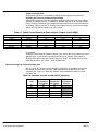
Table 3-7 Output Current Derating at Reduced Input Voltages (2.5KHz PWM)
Input Voltage
230VAC Control
460VAC Control
180VAC
340VAC
190VAC
360VAC
208VAC
400VAC
230VAC
440VAC
240VAC
480VAC
% of Output Current after Derating
240/480VAC Motor
230/440VAC Motor
208/400VAC Motor
77%
84%
93%
82%
89%
98%
90%
99%
100%
100%
100%
100%
100%
100%
100%
For example:
A 460VAC Control that has a 400VAC input line can provide 90% of the rated current to a
480VAC motor. In the Section 6 specifications we find our example 10HP control is
ZD22H410-EL has a continuous current rating of 15 Amps. The derated current can be
calculated as follows: 15A x 90% = 13.5A derated value.
Hardware Changes for Reduced Voltage Input
Size C+, D+,D, E, F and G+ controls all require modification for operation at a reduced
line voltage (less than rated nominal). Table 3-8 defines the modifications for each
enclosure size. Figure 3-1 shows the locations of the transformer locations for each
enclosure size.
Table 3-8 Hardware changes for 380-400VAC operation
Enclosure
Size
C+
D+
D
E
F
G+
3-12 Receiving & Installation
Control
Transformer
Tap Change
Yes
Yes
Yes
Yes
Yes
No
Contactor
Transformer
Tap Change
No
No
No
Yes
Yes
Yes
Fuse Block
Connection
Change
Yes
MN722
Section 1
General Information
Control Sizes
C+, D, D+
Figure 3-1 Control and Contactor Transformer Locations
Control Size
Control Size
E
F
Contactor
Transformer
Input
Contactor
Control
Transformer
Logic Control
Board
Input
Contactor
Control
Transformer
Control Size
G+
Fuse
Block
xfmr
Contactor
Transformer
Control
Transformer
Fan
Transformers
xfmr
Swing out panel
Contactor
Transformer
Input
Contactor
Not drawn to scale or proportion
Size C+, D, D+ E, and F size control procedure:
Control Transformer
MN722
1.
Terminate drive operation and disable the control.
2.
Remove all power sources from the control. If power has been applied, wait at
least 5 minutes for bus capacitors to discharge.
3.
Remove or open the front cover and locate the control transformer (Figure 3-2).
4.
Remove the wire from terminal 5 of the control transformer.
5.
Place the wire that was removed from terminal 5 onto terminal 4.
6.
Install or close the front cover.
Receiving & Installation 3-13
Figure 3-2 Configuring the Control Transformer for 380 - 400 VAC Installation
Contactor Transformer
Only size E and F controls require a change of the contactor transformer tap.
See Figure 3-3. Use the taps (H1 to H5) that are correct for the input voltage.
Figure 3-3 Contactor Transformer Tap Change (380 -400VAC Input)
600VAC
550VAC
380VAC
H4
Frequency
Voltage
Taps
50 / 60
Hz
380
440-460
550
600
H1 − H2
H1 − H3
H1 − H4
H1 − H5
H3
440VAC
H1
H5
H2
Size G+and H control procedure: (Refer to Figure 3-4.)
Control Transformer
1.
Be sure drive operation is terminated and control is disabled.
2.
Remove all power sources from the control. If power has been applied, wait at
least 5 minutes for bus capacitors to discharge.
3.
Remove or open the front cover. Locate the control transformer fuse block
(see Figure 3-1).
4.
Remove the wires from the two right side terminals (460VAC connection).
5.
Place the wires on the center terminals as shown (380VAC connection).
6.
Install or close the front cover.
Figure 3-4 Configuring the Control Transformer Fuse Block for 380 - 400 VAC Installation
For Fuse Block, location
refer to Figure 3-1.
3-14 Receiving & Installation
460VAC
380-400VAC
Connection
Connection
MN722
Section 1
General Information
Motor Connections
Motor connections are shown in Figure 3-5.
Figure 3-5 Motor Connections
Notes:
1. Metal conduit should be used. Connect conduits so the use of Load
Reactor or RC Device does not interrupt EMI/RFI shielding.
Baldor
Series 22H
Control
T1
T2
2.
See Line/Load Reactors described previously in this section.
3.
Use same gauge wire for Earth ground as for L1, L2 and L3.
T3
Note 1
A1
Note 2
B1
C1
*Optional
Load
Reactor
Note 1
* Optional components not provided with 22H Control.
A2
B2
C2
Note 3
T2 T3
T1
G
See recommended terminal tightening torques in Section 7.
* AC Motor
M-Contactor
If required by local codes or for safety reasons, an M-Contactor (motor circuit contactor)
may be installed. However, incorrect installation or failure of the M-contactor or wiring
may damage the control. If an M-Contactor is installed, the control must be disabled for
at least 20msec before the M-Contactor is opened or the control may be damaged.
M-Contactor connections are shown in Figure 3-6.
Figure 3-6 Optional M-Contactor Connections
T1
T2
T3
To Power Source
(Rated Coil Voltage)
M
M
M
T2 T3
T1
M=Contacts of optional M-Contactor
MN722
* M-Contactor
G
* Motor
*
M Enable
* Optional
RC Device
Electrocube
RG1781-3
J1
7
8
9
Note: Close “Enable”
after “M” contact closure.
See recommended terminal
tightening torques in Section 7.
Receiving & Installation 3-15
Section 1
General Information
Encoder Installation
Electrical isolation of the encoder shaft and housing from the motor is required. Electrical
isolation prevents capacitive coupling of motor noise that will corrupt the encoder signals.
Baldor provides shielded wire for encoder connection. Figure 3-7 shows the electrical
connections between the encoder and the encoder connector. Figure 3-8 shows the
connections between the encoder connector and J1 of the control.
Figure 3-7 Encoder Connections
J1
23
24
25
26
27
28
29
30
Electrically
Isolated
Encoder
A
A
B
B
C
C
+5V
COMMON
See recommended terminal
tightening torques in Section 7.
Figure 3-8 Control Connections
Encoder End
A
A
B
B
Index(C)
Index(C)
+5VDC
Common
Shield
Control End
J1-23
J1-24
J1-25
J1-26
J1-27
J1-28
J1-29
J1-30
J1-30
Single Ended Connections
Differential inputs are recommended for best noise immunity. If only single ended
encoder signals are available, connect them to A, B, and INDEX (C) (J1-23, J1-25 and
J1-27 respectively).
Buffered Encoder Output The control provides a buffered encoder output on pins J1-31 to J1-38. This output may
be used by external hardware to monitor the encoder signals. It is recommended that this
output only drive one output circuit load (a 26LS31 type device drives this output).
The resolution of this output is 4096 counts per revolution (1024 ppr x 4 = 4096). This
means that each channel (A+, A−, B+, B−) has 1024 counts per revolution.
The factory setting uses a two channel quadrature pulse train (identical to a standard
encoder pulse train). The waveform of the quadrature outputs is shown in Figure 3-9.
The channels are identified as A+, A−, B+ and B−. Where A and B channels are in
quadrature and A− is a complement of A, and B− is a complement of B.
Figure 3-9 Quadrature Output
A+
A−
B+
B−
Quadrature: A Leading B
3-16 Receiving & Installation
MN722
Section 1
General Information
Home (Orient) Switch Input The Home or Orient function is active in the Bipolar and Serial modes and causes the
motor shaft to rotate to a predefined home position. The homing function allows shaft
rotation in the drive forward direction only. The home position is located when a machine
mounted switch or the encoder “Index” pulse is activated (closed). Home is defined by a
rising signal edge at terminal J1-27. The shaft will continue to rotate only in a “Drive
Forward” direction for a user defined offset value. The offset is programmed in the Level
2 Miscellaneous Homing Offset parameter. The speed at which the motor will “Home” or
orient is set with the Level 2 Miscellaneous Homing Speed parameter.
A machine mounted switch may be used to define the Home position in place of the
encoder index channel. A differential line driver output from a solid state switch is
preferred for best noise immunity. Connect this differential output to terminals J1-27 and
J1-28.
A single ended solid-state switch or limit switch should be wired as shown in Figure 3-10.
Regardless of the type of switch used, clean rising and falling edges at J1-27 are required
for accurate positioning.
Note: A control may require dynamic brake hardware for Orient (Homing) function to
work. The control may trip without dynamic brake hardware installed.
Figure 3-10 Typical Home or Orient Switch Connections
J1
J1
+5V Input
Output
Common
27
28
29
30
5VDC Proximity Switch
INDEX
INDEX
27
INDEX
28
INDEX
+5V
Common
29
+5V
Common
30
Limit Switch (Closed at HOME).
See recommended terminal tightening torques in Section 7.
Example:
If the drive is operating in the forward direction when the “Orient” J1-11 input is closed,
the drive will decel at “DECEL #1” speed. Then continue in the forward direction at the
“Homing Speed” until the index pulse is received. The drive will continue past the int
index in the forward direction by the amount of the “Homing Offset”. The drive will then
stop and maintain position.
MN722
Receiving & Installation 3-17
Control Board Jumpers
Converter Section Control Board
Figure 3-11 Converter Control Board Jumper JP1 Location
Expansion Board
Motor Control Board
Keypad
Connector
321
JP1
See recommended terminal tightening
torques in Section 7.
Table 3-9 Converter Control Board Jumper
Jumper
JP1
Jumper Position
1−2
2−3
Description of Jumper Position Setting
Voltage Speed Command Signal. (Factory Setting)
4−20mA Speed Command Signal.
Inverter Section Control Board
Figure 3-12 Inverter Control Board Jumper Locations
JP2
1 2 3
Refer to Table 3-10
for jumper placement information.
1 2 3
JP1
See recommended terminal tightening torques in Section 7.
Table 3-10 Inverter Control Board Jumper
Jumper
JP1
JP2
Jumper Position
1-2
2-3
1-2
2-3
3-18 Receiving & Installation
Description of Jumper Position Setting
Voltage Speed Command Signal. (Factory Setting)
4-20mA input at Analog #2
Factory Setting
Not used.
MN722
Section 1
General Information
Analog Inputs
Two analog inputs are available: analog input #1 (J1-1 and J1-2) and analog input #2
(J1-4 and J1-5) as shown in Figure 3-13. Either analog input may be selected in the
Level 1 INPUT block, Command Select parameter value. Analog input #1 is selected if
the parameter value is “Potentiometer”. Analog input #2 is selected if the parameter
value is “+/-10Volts, +/-5 Volts or 4-20mA”. Figure 3-14 shows the equivalent circuits of
the Analog Inputs.
Figure 3-13 Analog Inputs and Outputs
J1
Analog GND
Command Pot or
0-10VDC
Analog Input 1
5KW
±5VDC, ±10VDC or 4-20 mA Input
Pot Reference
Analog Input +2
Analog Input -2
1
2
Analog Input 1
3
4
Analog Input 2
5
See recommended terminal tightening torques in Section 7.
Analog Input #1
(Single Ended)
When using a potentiometer as the speed command, process feedback or setpoint
source, the Level 1 Input block COMMAND SELECT parameter must be set to
“POTENTIOMETER”.
Note: A potentiometer value of 5kW to 10kW, 0.5 watt may be used.
Parameter Selection
The single ended analog input #1 can be used in one of three ways:
1. Speed or Torque command (Level 1 Input block, Command Select=Potentiometer).
2. Process Feedback (Level 2 Process Control block, Process Feedback=Potentiometer).
3. Setpoint Source (Level 2 Process Control block, Setpoint Source=Potentiometer).
When using Analog Input #1, the respective parameter must be set to
“POTENTIOMETER”.
Analog Input #2
(Differential)
Analog input #2 accepts a differential command 0-5VDC, 0-10VDC, ±5VDC, ±10VDC or
4-20 mA. If pin J1-4 is positive with respect to pin 5, the motor will rotate in the forward
direction. If pin J1-4 is negative with respect to pin 5, the motor will rotate in the reverse
direction. JP1 must be set for voltage or current operation as required. Analog Input #2
can be connected for single ended operation by grounding either of the inputs, provided
the common mode voltage range is not exceeded.
Note: The common mode voltage can be measured with a voltmeter. Apply the
maximum command voltage to analog input 2 (J1-4, 5). Measure the AC and
DC voltage across J1-1 to J1-4. Add the AC and DC readings together.
Measure the AC and DC voltage from J1-1 to J1-5. Add the AC and DC
readings together.
If either of these measurement totals exceeds a total of ±15 volts, then the
common mode voltage range has been exceeded. To correct this condition,
either change the command source or isolate the command signal with a
signal isolator.
MN722
Receiving & Installation 3-19
Section 1
General Information
Figure 3-14 Analog Inputs Equivalent Circuits
J1
30KW
5.1V Zener
-15VDC
Notes:
.033 mF
1
+
−
5KW
Analog Ground is separated from
Chassis Ground. Electrically they
are separated by an RC network.
20KW
2
−
To Microprocessor
+
See recommended terminal tightening
torques in Section 7.
1.96KW
3
4
5
+15VDC
10KW
JP1
4-20mA
Analog Outputs
10KW
+
To Microprocessor
−
500W
X N/C
All OP Amps are TL082 or TL084
10KW
10KW
Two programmable analog outputs are provided on J1-6 and J1-7. See Figure 3-15.
These outputs are scaled 0 - 5 VDC (1mA maximum output current) and can be used to
provide real-time status of various control conditions. The output conditions are defined
in Table 4-4 of Section 4 of this manual.
The return for these outputs is J1-1 analog ground. Each output is programmed in the
Level 1 Output block.
Figure 3-15 Analog Outputs Equivalent Circuits
J1
1
+
10KW
+
From Microprocessor
.033 mf
3-20 Receiving & Installation
6
−
−
All OP Amps are TL082 or TL084
Analog Ground is separated from
Chassis Ground. Electrically they
are separated by an RC network.
10KW
+
.033 mf
50W
−
10KW
From Microprocessor
Notes:
50W
See recommended terminal tightening
torques in Section 7.
7
10KW
MN722
Section 1
General Information
Control Circuit Connections
There are two control boards in a Series 22H Vector Control. The Converter Control
Board is used to rectify and process the incoming power. The Inverter Control Board
provides the inverting and power output functions. The keypad is normally connected to
the Inverter Control Board. Each converter board has its own J1 terminal strip. The
Inverter Control Board provides the user interface for most external connections.
Converter Control Board Connections
All necessary connections for the Converter Control Board have been made at the factory
prior to shipment.
The jumper between J1-8 and J1-17 provides the enable signal to allow converter
operation. The jumper between J1-39 and J1-40 provides +24VDC from the internal
supply to allow the opto isolated input at J1-8 to operate. These jumpers should remain
installed at all times.
Sometimes it is necessary to troubleshoot the converter section using the isolated opto
outputs. Figure 3-16 shows how to connect external relays to the board to “Sink” or
“Source” the relay current.
The function of each opto output is as follows: (these functions cannot be changed)
J1-19
Ready
J1-20
At Voltage
J1-21
Fault
J1-22
Overtemperature Warning
Figure 3-16 Converter Control Board Opto Output Wiring
24Com
Optional
Customer
Supplied
Relays &
Diodes
17
18
39
19
20
21
22
41
42
43
44
Using Internal Supply
(Sinking the Relay Current)
Note: Add appropriately rated
protective device for AC relay
(snubber) or DC relay (diode).
MN722
+24VDC
24Com
17
18
39
19
20
21
22
41
42
43
44
+24VDC
Optional
Customer
Supplied
Relays &
Diodes
Using Internal Supply
(Sourcing the Relay Current)
See recommended terminal tightening torques in Section 7.
Receiving & Installation 3-21
Section 1
General Information
Inverter Control Board Connections
Ten operating modes are available in the Series 22H vector control. These operating
modes define the basic motor control setup and the operation of the input and output
terminals. After the circuit connections are completed, the operating mode is selected by
programming the Level 1 Input block, Operating Mode parameter.
Available operating modes include:
•
Keypad Control
•
Standard Run, 3 Wire Control
•
15 Speed, 2 Wire Control
•
Three Speed, 2 Wire Control
•
Three Speed, 3 Wire Control
•
Serial
•
Bipolar Speed or Torque
•
Process Control
•
EPOT, 2 Wire Control
•
EPOT, 3 Wire Control
Each mode requires connections to the J1 terminal strip (except keypad and serial
modes, all connections are optional). The J1 terminal strip is shown in Figure 3-17. The
connection of each input or output signal is described in the following pages.
Figure 3-17 Control Signal Connections
J1
Analog GND
Analog Input 1
Refer to Analog Inputs
Pot Reference
Analog Input +2
Analog Input -2
Analog Out 1
Refer to Analog Outputs
Analog Out 2
Input #1
Input #2
Input #3
Input #4
Input #5
Refer to opto isolated Inputs
Input #6
Input #7
Input #8
Input #9
Opto In Common
Opto Out #1
Refer to opto isolated Outputs
Opto Out #2
Opto Out #3
Opto Out #4
A
1
23
2
24
A
3
25
B
4
26
B
5
27
INDEX
6
28
INDEX
7
29
+5VDC
8
30
Common
9
31
A
10
32
A
11
33
B
12
34
B
13
35
INDEX
14
36
INDEX
15
37
Not Used
16
38
Common
17
39
18
40
19
41 Opto Out #1 Return
20
42 Opto Out #2 Return
21
43 Opto Out #3 Return
22
44 Opto Out #4 Return
Refer to Encoder Installation
Refer to Buffered Encoder Output
+24VDC
Opto In Power
J1-39 & 40 Jumper as shown to power
the opto inputs from the
internal +24VDC supply.
Note:
J1-18 and J1-41 are connected
together on the control circuit
board.
See recommended terminal tightening torques in Section 7.
Serial Mode
3-22 Receiving & Installation
The Serial operating mode requires one of the optional Serial Interface expansion boards
(RS232 or 422/485). Installation and operation information for these serial expansion
boards is provided in Serial Communications expansion board manual MN1310. This
manual is shipped with the serial expansion board.
MN722
Section 1
General Information
Keypad Mode Connections The Keypad operating mode allows the control to be operated from the keypad. This
mode requires no connections to J1. However, the Enable, Stop and External Trip inputs
may optionally be used. All other opto inputs remain inactive. The analog outputs and
opto-outputs remain active at all times. See Figure 3-18.
Parameter Selection
For operation in Keypad mode, set the Level 1 Input block, Operating Mode parameter to
Keypad. The STOP key can operate in two ways:
Press STOP key one time to brake or coast to stop.
Press STOP key two times to disable control.
To use the Enable input, J1-8 must be connected and the Local Enable INP parameter in
the Level 2 Protection block must be set to ON. The Enable line is normally closed.
When opened, the motor will COAST to a stop. When the enable line is again closed, the
motor will not start until a new direction command is received from the keypad.
To use the Stop input, J1-11 must be connected and the Level 1 Keypad Setup block,
LOC. Hot Start parameter must be set to ON. The Stop line is normally closed. When
opened, the motor will COAST or REGEN to a stop depending upon the setting of Level 1
Keypad Setup block Keypad Stop Mode parameter value. Closing the input will
immediately start the motor.
The External Trip input causes a fault condition during a motor over temperature
condition (when normally closed input opens). The External Trip input (J1-16) must be
connected and the External Trip parameter in the Level 2 Protection block must be set to
“ON”. When J1-16 is opened, an external trip fault occurs. The control will disable and
the motor coasts to a stop. An external trip fault is displayed on the keypad display (also
logged into the fault log).
Figure 3-18 Keypad Control Connection Diagram
J1-8
J1-11
J1-16
If J1-8 is connected, you must set Level 2 Protection block, Local Enable INP
parameter to “ON” to activate the opto input.
CLOSED allows normal operation.
OPEN disables the control and motor coasts to a stop.
If J1-11 is connected, you must set Level 1 Keypad Setup block,
Loc. Hot Start parameter to to “ON” to activate the opto input.
CLOSED allows normal operation.
OPEN motor decels to stop (depending on Keypad Stop mode). The motor
will restart when J1-11 closes after open (if the keypad FWD or REV key is
still pressed).
If J1-16 is connected, you must set Level 2 Protection block, External Trip to
“ON” to activate the opto input.
CLOSED allows normal operation.
OPEN causes an external trip to be received by the control. The control will
disable and display external trip. When this occurs, the motor stop command
is issued, drive operation is terminated and an external trip fault is displayed
on the keypad display (also logged into the fault log).
J1
Analog GND
Analog Input 1
No Connection
Enable
Pot Reference
Analog Input +2
Analog Input -2
Analog Out 1
Analog Out 2
Input #1
Input #2
1
2
3
4
5
6
7
8
9
Input #3
10
Stop
Input #4
11
Input #5
12
Input #6
13
Input #7
14
Input #8
15
Input #9
External Trip
16
Opto In Common
17
Refer to Figure 3-27.
See recommended terminal tightening torques in Section 7.
MN722
Receiving & Installation 3-23
Section 1
General Information
Standard Run 3 Wire Mode Connections
In Standard Run mode, the control is operated by the opto isolated inputs at J1-8 through
J1-16 and the analog command input. The opto inputs can be switches as shown in
Figure 3-19 or logic signals from another device. The external trip opto input at J1-16 is
active if connected as shown and the Level 2 Protection block, External Trip parameter is
set to ON.
For 4−20mA operation, refer to Table 3-10. Analog input 2 can then be used for 4−20mA
operation.
Figure 3-19 Standard Run 3-Wire Connection Diagram
J1-8
J1-9
J1-10
J1-11
J1-12
J1-13
J1-14
J1-15
J1-16
CLOSED allows normal control operation.
OPEN disables the control and motor coasts to a stop.
MOMENTARY CLOSED starts motor operation in the Forward direction.
In JOG mode (J1-12 CLOSED), continuous CLOSED jogs motor in the
Forward direction.
MOMENTARY CLOSED starts motor operation in the Reverse direction.
In JOG mode (J1-12 CLOSED), CONTINUOUS closed JOGS motor in the
Reverse direction.
MOMENTARY OPEN causes motor to decel to stop (depending on Keypad
Stop Mode parameter setting). Motor current continues to be applied to the
motor.
CLOSED places control in JOG mode, Forward and Reverse run are used
to jog the motor.
CLOSED selects group 2.
OPEN selects ACC / DEC / S-CURVE group 1.
CLOSED selects preset speed #1, (J1-12, will override this preset speed).
OPEN allows speed command from Analog input #1 or #2 or Jog.
CLOSED to reset fault condition.
OPEN to run.
If J1-16 is connected, you must set Level 2 Protection block, External Trip
to “ON” to activate the opto input.
CLOSED allows normal control operation.
OPEN causes an external trip to be received by the control. The control
will disable and display external trip. When this occurs, the motor stop
command is issued, drive operation is terminated and an external trip fault
is displayed on the keypad display (also logged into the fault log).
3-24 Receiving & Installation
Command Pot or
0-10VDC
5KW
Programmable Output
Programmable Output
J1
Analog GND
Analog Input 1
Pot Reference
Analog Input +2
Analog Input -2
Analog Out 1
Analog Out 2
Enable
Forward Run
1
2
3
4
5
6
7
8
9
Reverse Run
10
Stop
11
Jog
12
Accel/Decel
13
Preset Speed #1
14
Fault Reset
15
External Trip
16
Opto In Common
17
Refer to Figure 3-27.
See recommended terminal
tightening torques in Section 7.
MN722
Section 1
General Information
15 Speed 2-Wire Mode Connections Switch Truth Table is defined in Table 3-11.
Operation in the 15 Speed 2-Wire mode is controlled by the Opto Isolated inputs at J1-8
through J1-16. The Opto inputs can be switches as shown in Figure 3-20 or logic signals
from another device.
Switched inputs at J1-11 through J1-14 allow selection of 15 preset speeds and provide
Fault Reset as defined in Table 3-11.
Figure 3-20 15 Speed 2-Wire Control Connection Diagram
CLOSED allows normal control operation.
OPEN disables the control and motor coasts to a stop.
J1-9
CLOSED operates the motor in the Forward direction (with J1-10 open).
OPEN motor decels to stop (depending on Keypad Stop mode parameter
setting).
J1-10
CLOSED operates motor in the Reverse direction (with J1-9 open).
OPEN motor decels to stop depending on Keypad Stop mode parameter
setting.
J1-11 to 14 Selects programmed preset speeds as defined in Table 3-11.
J1-15
Selects ACC/DEC group. OPEN selects group 1. CLOSED selects
group 2.
J1-16
If J1-16 is connected, you must set Level 2 Protection block, External
Trip to “ON” to activate the opto input.
CLOSED allows normal control operation.
OPEN causes an external trip to be received by the control. The control
will disable and display external trip. When this occurs, the motor stop
command is issued, drive operation is terminated and an external trip
fault is displayed on the keypad display (also logged into the fault log).
J1
J1-8
Analog GND
No Connection
Programmable Output
Programmable Output
Analog Input 1
Pot Reference
Analog Input +2
Analog Input -2
Analog Out 1
Analog Out 2
Enable
Forward Run
1
2
3
4
5
6
7
8
9
Reverse Run
10
Switch 1
11
Switch 2
12
Switch 3
13
Switch 4
14
Accel/Decel/S Select 1
15
External Trip
16
Opto In Common
17
Refer to Figure 3-27.
See recommended terminal tightening torques in Section 7.
Table 3-11 Switch Truth Table for 15 Speed, 2 Wire Control Mode
Function
Preset 1
Preset 2
Preset 3
Preset 4
Preset 5
Preset 6
Preset 7
Preset 8
Preset 9
Preset 10
Preset 11
Preset 12
Preset 13
Preset 14
Preset 15
Fault Reset
MN722
J1-11
Open
Closed
Open
Closed
Open
Closed
Open
Closed
Open
Closed
Open
Closed
Open
Closed
Open
Closed
J1-12
Open
Open
Closed
Closed
Open
Open
Closed
Closed
Open
Open
Closed
Closed
Open
Open
Closed
Closed
J1-13
Open
Open
Open
Open
Closed
Closed
Closed
Closed
Open
Open
Open
Open
Closed
Closed
Closed
Closed
J1-14
Open
Open
Open
Open
Open
Open
Open
Open
Closed
Closed
Closed
Closed
Closed
Closed
Closed
Closed
Receiving & Installation 3-25
Section 1
General Information
3 Speed Analog 2 Wire Operating Mode
Allows selection of 3 preset speeds with 2 wire inputs. The opto inputs can be switches
as shown in Figure 3-21 or logic signals from another device.
The values of the preset speeds are set in the Level 1 Preset Speeds block, Preset
Speed #1, Preset Speed #2 and Preset Speed #3.
Figure 3-21 3 SPD ANA 2 Wire Control Connection Diagram
J1-8
CLOSED allows normal operation.
OPEN disables the control and the motor coasts to a stop.
J1-9
CLOSED operates the motor in the Forward direction (with J1-10 open).
OPEN motor decels to stop (depending on Keypad Stop mode).
J1-10
CLOSED operates the motor in the Reverse direction (with J1-9 open).
OPEN motor decels to stop (depending on Keypad Stop mode).
Note: Closing both J1-9 and J1-10 at the same time will reset a fault condition.
J1-11
CLOSED selects Analog Input #1.
OPEN selects Level 1 Input block, Command Select parameter.
Note: If Command Select (Level 1 Input block) is set to Potentiometer, then Analog
Input #1 is always selected regardless of this switch position.
J1-12
CLOSED selects STOP/START and Reset commands from terminal strip.
OPEN selects STOP/START and Reset commands from Keypad.
J1-13
CLOSED selects Level 1 Input block, Command Select parameter.
OPEN selects speed commanded from Keypad.
Note: When changing from Terminal Strip to Keypad (J1-12 or J1-13) the motor speed
and direction will remain the same after the change.
Command Pot or
0-10VDC
5KW
J1
Analog GND
Analog Input 1
Pot Reference
Analog Input +2
Analog Input -2
Analog Out 1
Analog Out 2
Enable
Forward Run
1
2
3
4
5
6
7
8
9
Reverse Run
10
Analog Input Select
11
Run Command
12
Speed Command
13
Switch 1
14
Switch 2
15
External Trip
16
Opto In Common
17
J1-14
Selects preset speeds as defined in the Speed Select Table (Table 3-12).
J1-15
Selects preset speeds as defined in the Speed Select Table (Table 3-12).
J1-16
If J1-16 is connected, you must set Level 2 Protection block, External Trip to “ON” Refer to Figure 3-27.
to activate the opto input.
See recommended terminal
CLOSED allows normal operation.
tightening torques in Section 7.
OPEN causes an external trip to be received by the control. The control will disable
and display external trip. When this occurs, the motor stop command is issued,
drive operation is terminated and an external trip fault is displayed on the keypad
display (also logged into the fault log).
Table 3-12 Speed Select Table
3-26 Receiving & Installation
J1-14
J1-15
OPEN
OPEN
CLOSED
OPEN
CLOSED
OPEN
CLOSED
CLOSED
Command
Analog Input
(Command Select)
Preset #1
Preset #2
Preset #3
MN722
Section 1
General Information
3 Speed Analog 3 Wire Operating Mode
Allows selection of 3 preset speeds with 3 wire inputs. The opto inputs can be switches
as shown in Figure 3-22 or logic signals from another device.
The values of the preset speeds are set in the Level 1 Preset Speeds block, Preset
Speed #1, Preset Speed #2 and Preset Speed #3.
Figure 3-22 3 SPD ANA 3 Wire Control Connection Diagram
J1-8
CLOSED allows normal operation.
OPEN disables the control and the motor coasts to a stop.
J1-9
MOMENTARY CLOSED starts motor operation in the Forward direction.
J1-10
MOMENTARY CLOSED starts motor operation in the Reverse direction.
Note: Closing both J1-9 and J1-10 at the same time will reset a fault condition.
J1-11
Momentary OPEN motor decels to stop (depending on Keypad Stop mode).
J1-12
CLOSED selects STOP/START and Reset commands from terminal strip.
OPEN selects STOP/START and Reset commands from Keypad.
J1-13
CLOSED selects Level 1 Input block, Command Select parameter.
OPEN selects speed commanded from Keypad.
Note: When changing from Terminal Strip to Keypad (J1-12 or J1-13) the motor
speed and direction will remain the same after the change.
J1-14
Selects preset speeds as defined in the Speed Select Table (Table 3-13).
J1-15
Selects preset speeds as defined in the Speed Select Table (Table 3-13).
J1-16
If J1-16 is connected, you must set Level 2 Protection block, External Trip to
“ON” to activate the opto input.
CLOSED allows normal operation.
OPEN causes an external trip to be received by the control. The control will
disable and display external trip. When this occurs, the motor stop command
is issued, drive operation is terminated and an external trip fault is displayed on
the keypad display (also logged into the fault log).
Command Pot or
0-10VDC
5KW
J1
Analog GND
Analog Input 1
Pot Reference
Analog Input +2
Analog Input -2
Analog Out 1
Analog Out 2
Enable
Forward Run
Reverse Run
1
2
3
4
5
6
7
8
9
10
Stop
11
Run Command
12
Speed Command
13
Switch 1
14
Switch 2
15
External Trip
16
Opto In Common
17
Refer to Figure 3-27.
See recommended terminal
tightening torques in Section 7.
Table 3-13 Speed Select Table
MN722
J1-14
J1-15
OPEN
OPEN
CLOSED
OPEN
CLOSED
OPEN
CLOSED
CLOSED
Command
Analog Input
(Command Select)
Preset #1
Preset #2
Preset #3
Receiving & Installation 3-27
Section 1
General Information
Bipolar Speed and Torque Mode Connections
Provides bipolar speed or torque control. Also, you may store up to four (4) complete
sets of operating parameters. This is important if you wish to store and use different
acceleration rates, speed commands, jog speeds or to store tuning parameter values for
different motors etc. The opto inputs can be switches as shown in Figure 3-23 or logic
signals from another device.
Figure 3-23 Bipolar Speed or Torque Connection Diagram
J1-8
CLOSED allows normal operation.
OPEN disables the control & motor coasts to a stop.
J1-9
CLOSED to enable operation in the Forward direction.
OPEN TO DISABLE Forward operation (drive will brake to a stop if a Forward
command is still present).
Reverse operation is still possible if J1-10 is closed.
J1-10
Command Pot or
0-10VDC
5KW
CLOSED to enable operation in the Reverse direction.
OPEN to disable Reverse operation (drive will brake to a stop if a Reverse
command is still present).
Forward operation is still possible if J1-9 is closed.
CLOSED causes the motor to rotate in the forward direction until the load
reaches a marker or external switch location.
OPEN allows normal operation.
J1-12
CLOSED puts the control in torque command mode.
OPEN puts the control in speed (velocity) command mode.
Note: If a stop command is issued while in the torque (current) mode, the
control will stop but will not maintain position (zero current). This is
different than zero speed operation for the velocity mode.
J1-13 & 14 Select from four parameter tables as defined in Table 3-14.
J1-15
Momentary CLOSED to reset fault condition.
OPEN allows normal operation.
J1-16
If J1-16 is connected, you must set Level 2 Protection block, External Trip to
“ON” to activate the opto input.
CLOSED allows normal operation.
OPEN causes an external trip to be received by the control. The control will
disable and display external trip. When this occurs, the motor stop command
is issued, drive operation is terminated and an external trip fault is displayed
on the keypad display (also logged into the fault log).
Analog Input +2
Analog Input -2
Analog Out 1
Analog Out 2
1
2
3
4
5
6
7
Enable
8
Forward Enable
9
Reverse Enable
10
Homing
11
Speed/Torque
12
Switch 1
13
Switch 2
14
Fault Reset
15
External Trip
16
Opto In Common
17
Note: If J1-9 and J1-10 are both opened, the drive will brake to a stop.
J1-11
J1
Analog GND
Analog Input 1
Pot Reference
Refer to Figure 3-27.
See recommended terminal
tightening torques in Section 7.
Table 3-14 Bipolar Mode Table Select Truth Table
Function
J1-13
J1-14
Parameter Table #0
Open
Open
Parameter Table #1
Closed
Open
Parameter Table #2
Open
Closed
Parameter Table #3
Closed
Closed
Note: See multiple parameter sets.
3-28 Receiving & Installation
MN722
Section 1
General Information
Multiple Parameter Sets
The following procedure allows you to program up to four complete sets of parameter
values and to use these multiple parameter sets. When programming each parameter
set, use the ENTER key to accept and automatically save parameter values.
Note: The control can be programmed in the REMOTE mode with the drive enabled.
The control must be disabled to change the operating mode parameter and
the operating mode can not be stored in a parameter table.
1. If this is a new installation, do this procedure after the Pre-Operation Checklist
and Power-Up Procedures at the end of this section.
2.
Set the Level 1 INPUT block, Operating Mode parameter value to BIPOLAR in
each of the parameter sets.
3.
Set switches J1-13 and J1-14 to Parameter Table #0 (both switches open). Be
sure switches J1-9 and J1-10 are OPEN, J1-8 is CLOSED. Enter all parameter
values, and autotune as instructed in Section 3 of this manual. This creates
and saves the first parameter set which is numbered Table#0.
4.
Set switches J1-13 and J1-14 to Parameter Table #1. Be sure switches J1-9
and J1-10 are OPEN, J1-8 is CLOSED. Enter all parameter values, and
autotune as instructed in Section 3 of this manual. This creates and saves the
second parameter set which is numbered Table#1.
5.
Set switches J1-13 and J1-14 to Parameter Table #2. Be sure switches J1-9
and J1-10 are OPEN, J1-8 is CLOSED. Enter all parameter values, and
autotune as instructed in Section 3 of this manual. This creates and saves the
third parameter set which is numbered Table#2.
6.
Set switches J1-13 and J1-14 to Parameter Table #3. Be sure switches J1-9
and J1-10 are OPEN, J1-8 is CLOSED. Enter all parameter values, and
autotune as instructed in Section 3 of this manual. This creates and saves the
final parameter set which is numbered Table#3.
7.
Remember that to change the value of a parameter in one of the parameter
tables, you must first select the table using the switches. You cannot change a
value in a table until you have first selected that table.
Note: Preset speed does not apply to table select.
MN722
Receiving & Installation 3-29
Section 1
General Information
Process Mode Connections The process control mode provides an auxiliary closed loop general purpose PID set point
control. The process control loop may be configured in various ways and detailed
descriptions of the process mode are given in MN707 “Introduction to Process Control”.
The opto inputs can be switches as shown in Figure 3-24 or logic signals from another device.
Figure 3-24 Process Mode Connection Diagram
J1-8
CLOSED allows normal operation.
OPEN disables the control & motor coasts to a stop.
J1-9
CLOSED to enable operation in the Forward direction.
OPEN TO DISABLE Forward operation (drive will brake to a stop if a Forward
command is still present). Reverse operation is still possible if J1-10 is closed.
J1-10
CLOSED to enable operation in the Reverse direction.
OPEN to disable Reverse operation (drive will brake to a stop if a Reverse
command is still present). Forward operation is still possible if J1-9 is closed.
Note: If J1-9 and J1-10 are both opened, the drive will brake to a stop.
J1-11
CLOSED = TABLE 1, OPEN = TABLE 0. (See multiple parameter sets.)
J1-12
CLOSED, the control is in torque command mode.
OPEN, the control is in speed (velocity) command mode.
Note: If a stop command is issued while in the torque (current) mode, the control
will stop but will not maintain position (zero current). This is different than
zero speed operation for the velocity mode.
J1-13
CLOSED to enable the Process Mode.
J1-14
CLOSED places control in JOG mode. The control will only JOG in the forward
direction.
J1-15
CLOSED to reset a fault condition.
OPEN to run.
J1-16
If J1-16 is connected, you must set Level 2 Protection block, External Trip to “ON”
to activate the opto input.
CLOSED allows normal operation.
OPEN causes an external trip to be received by the control. The control will
disable and display external trip. When this occurs, the motor stop command is
issued, drive operation is terminated and an external trip fault is displayed on the
keypad display (also logged into the fault log).
J1
Command Pot or
0-10VDC
5KW
Analog GND
Analog Input 1
Pot Reference
Analog Input +2
Analog Input -2
Analog Out 1
Analog Out 2
Enable
Forward Enable
1
2
3
4
5
6
7
8
9
Reverse Enable
10
Table Select
11
Speed/Torque
12
Process Mode Enable
13
Jog
14
Fault Reset
15
External Trip
16
Opto In Common
17
Refer to Figure 3-27.
See recommended terminal tightening torques in Section 7.
Table 3-15 Process Mode Input Signal Compatibility
Feedback
Setpoint or
Feedforward
J1-1 & 2
J1-4 & 5
5V EXB
10V EXB
4-20mA EXB
3-15 PSI EXB
DC Tach EXB
EXB PULSE FOL Serial EXB ËËË
ËËË
J1-1 & 2
J1-4 & 5
5V EXB
10V EXB
4-20mA
EXB
3-15 PSI
EXB
ËËËËË
ËËËËË
ËËËËË
ËËËËË
ËËËËË
ËËËËË
ËËËË
ËËËËËËËËËËËËËËËËËËË
ËËËËËËËËËËËËËËËËËËË
ËËËËËËËËËËËËËËËËËËË
DC
Tach EXB
Requires expansion board EXB007A01 (High Resolution Analog I/O EXB).
Requires expansion board EXB004A01 (4 Output Relays/3-15 PSI Pneumatic Interface EXB).
Requires expansion board EXB006A01 (DC Tachometer Interface EXB).
Requires expansion board EXB005A01 (Master Pulse Reference/Isolated Pulse Follower EXB).
Used for Feedforward only. Must not be used for Setpoint Source or Feedback.
Requires expansion board EXB001A01 (RS232 Serial Communication EXB). or
Requires expansion board EXB002A01 (RS422/RS485 High Speed Serial Communication EXB). or
Requires expansion board EXB012A01 (RS232/RS485 Serial Communication EXB).
Conflicting inputs. Do not use same input signal multiple times.
Conflicting level 1 or 2 expansion boards. Do not use!
3-30 Receiving & Installation
MN722
Section 1
General Information
Electronic Pot 2 Wire Operating Mode
Provides speed Increase and Decrease inputs to allow EPOT operation with 2 wire
inputs. The opto inputs can be switches as shown in Figure 3-25 or logic signals from
another device. The values of the preset speeds are set in the Level 1 Preset Speeds
block, Preset Speed #1 or Preset Speed #2.
Figure 3-25 EPOT, 2 Wire Control Connection Diagram
J1-8
CLOSED allows normal operation.
OPEN disables the control and motor coasts to a stop.
J1-9
CLOSED starts motor operation in the Forward direction.
OPEN motor decels to stop (depending on Keypad Stop mode).
J1-10
CLOSED starts motor operation in the Reverse direction.
OPEN motor decels to stop (depending on Keypad Stop mode).
Command Pot or
0-10VDC
5KW
J1
Analog GND
Analog Input 1
Pot Reference
Analog Input +2
Analog Input -2
Analog Out 1
Analog Out 2
Enable
Forward Run
Note: Closing both J1-9 and J1-10 at the same time will reset a fault condition.
J1-11
Selects preset speeds as defined in the Speed Select Table (Table 3-16).
J1-12
Selects preset speeds as defined in the Speed Select Table (Table 3-16).
J1-13
CLOSED selects ACC / DEC / S-CURVE group 2.
OPEN selects ACC / DEC / S-CURVE group 1.
J1-14
Momentary CLOSED increases motor speed while contact is closed.
J1-15
Momentary CLOSED decreases motor speed while contact is closed.
J1-16
If J1-16 is connected, you must set Level 2 Protection block, External Trip
to “ON” to activate the opto input.
CLOSED allows normal operation.
OPEN causes an external trip to be received by the control. The control will
disable and display external trip. When this occurs, the motor stop
command is issued, drive operation is terminated and an external trip fault
is displayed on the keypad display (also logged into the fault log).
1
2
3
4
5
6
7
8
9
Reverse Run
10
Switch 1
11
Switch 2
12
Accel/Decel
13
Increase
14
Decrease
15
External Trip
16
Opto In Common
17
Refer to Figure 3-27.
See recommended terminal
tightening torques in Section 7.
Table 3-16 Speed Select Table
J1-11
J1-12
OPEN
CLOSED
OPEN
CLOSED
OPEN
OPEN
CLOSED
CLOSED
Function
Electronic Pot
Command Select *
Preset #1
Preset #2
* Command Select refers to the Level 1 Command Select parameter.
MN722
Receiving & Installation 3-31
Section 1
General Information
Electronic Pot 3 Wire Control Mode
Provides speed Increase and Decrease inputs to allow EPOT operation with 3 wire
inputs. The opto inputs can be switches as shown in Figure 3-26 or logic signals from
another device.
Figure 3-26 EPOT, 3 Wire Control Connection Diagram
J1-8
J1
CLOSED allows normal operation.
OPEN disables the control and motor coasts to a stop.
J1-9
Momentary CLOSED starts motor operation in the Forward direction.
J1-10
Momentary CLOSED starts motor operation in the Reverse direction.
Note: Closing both J1-9 and J1-10 at the same time will reset a fault condition.
J1-11
Momentary OPEN motor decels to stop (depending on Keypad Stop mode).
J1-12
CLOSED selects Level 1 Command Select parameter value.
OPEN selects EPOT.
J1-13
CLOSED selects ACC / DEC / S-CURVE group 2.
OPEN selects ACC / DEC / S-CURVE group 1.
J1-14
Momentary CLOSED increases motor speed while contact is closed.
J1-15
Momentary CLOSED decreases motor speed while contact is closed.
J1-16
If J1-16 is connected, you must set Level 2 Protection block, External Trip to
“ON” to activate the opto input.
CLOSED allows normal operation.
OPEN causes an external trip to be received by the control. The control will
disable and display external trip. When this occurs, the motor stop command
is issued, drive operation is terminated and an external trip fault is displayed
on the keypad display (also logged into the fault log).
Command Pot or
0-10VDC
5KW
Analog GND
Analog Input 1
Pot Reference
Analog Input +2
Analog Input -2
Analog Out 1
Analog Out 2
Enable
1
2
3
4
5
6
7
8
Forward Run
9
Reverse Run
10
Stop
11
EPOT/Command Select
12
Accel/Decel
13
Increase
14
Decrease
15
External Trip
16
Opto In Common
17
Refer to Figure 3-27.
See recommended terminal
tightening torques in Section 7.
3-32 Receiving & Installation
MN722
Section 1
General Information
External Trip Input
To activate the External Trip input, the External Trip parameter in the programming
Protection Block must be set to “ON”.
Terminal J1-16 is available for connection to a normally closed thermostat or overload
relay in all operating modes as shown in Figure 3-27. The thermostat or overload relay
should be a dry contact type with no power available from the contact. If the motor
thermostat or overload relay activates the control will automatically shut down and give
an External Trip fault.
Connect the External Trip Input wires to J1-16 and J1-17. Do not place these wires in the
same conduit as the motor power leads.
Figure 3-27 Motor Temperature Relay
T1
T2
T3
Customer Provided
Source Voltage
External or remote motor
overload protection may
be required by National
Electrical Code or equivalent
Note: Add appropriately rated
protective device for AC relay
(snubber) or DC relay (diode).
J1
*
CR1
M
M
See recommended terminal
tightening torques in Section 7.
16
17
External Trip
Do not run these wires in
same conduit as motor
leads or AC power wiring.
M
T2 T3 G
T1
Motor Thermostat Leads
* Motor
* Optional hardware. Must be ordered separately.
The equivalent circuit for the nine Opto inputs is shown in Figure 3-28. The function of
each input depends on the operating mode selected and are described previously in this
section. This Figure also shows the connections using the internal opto input Supply.
Opto-Isolated Inputs
Figure 3-28 Opto-Input Equivalent Circuit (Using Internal Supply)
J1
Opto In #1
Opto In #2
Opto In #3
Opto In #4
Opto In #5
Opto In #6
Opto In #7
Opto In #8
Opto In #9
Opto In Common
+24VDC @ 200mA
(supply terminal 39).
Jumper terminals 39 to 40
(Factory Installed)
MN722
8
9
10
11
12
13
14
15
16
17
39
6.8K
6.8K
6.8K
6.8K
6.8K
6.8K
6.8K
6.8K
6.8K
40
See recommended terminal tightening torques in Section 7.
Receiving & Installation 3-33
Section 1
General Information
Figure 3-29 Opto-Input Equivalent Circuit (Using External Supply)
Opto In #1
Opto In #2
Opto In #3
Opto In #4
Opto In #5
Opto In #6
Opto In #7
Opto In #8
Opto In #9
J1
Opto In #1
8
Opto In #2
9
Opto In #3
10
Opto In #4
11
Opto In #5
12
Opto In #6
13
Opto In #7
14
Opto In #8
15
Opto In #9
16
17
* User VCC (-)
Opto Inputs Closing to Ground
Opto-Isolated Outputs
9
10
11
See recommended terminal
tightening torques in Section 7.
12
13
14
15
16
* User VCC = 10 - 30VDC
39
* User VCC (-)
40
8
17
* User VCC (+)
39
* User VCC (+)
J1
External Power Source
40
Opto Inputs Closing to +VCC
Four programmable Opto-isolated outputs are available at terminals J1-19 through J1-22.
See Figure 3-30. Each output may be programmed to represent one output condition.
The output conditions are defined in Table 4-4 of Section 4 of this manual.
The Opto-isolated outputs may be configured for sinking or sourcing 50 mA each.
However, all must be configured the same. The maximum voltage from opto output to
common when active is 1.0 VDC (TTL compatible). The Opto-isolated outputs may be
connected in different ways as shown in Figure 3-30. The equivalent circuit for the
Opto-isolated outputs is shown in Figure 3-31.
If the opto outputs are used to directly drive a relay, a flyback diode rated at 1A, 100 V
(IN4002) minimum should be connected across the relay coil. See Electrical Noise
Considerations in Section 5 of this manual.
Each Opto Output is programmed in the Output programming block.
Figure 3-30 Opto-isolated Output Configurations
24Com
Optional
Customer
Supplied
Relays &
Diodes
17
39
18
19
20
21
22
24Com
+24VDC
17
39
41
42
43
18
19
20
21
41
42
43
44
22
44
Optional
Customer
Supplied
Relays &
Diodes
Using Internal Supply
(Sourcing the Relay Current)
Using Internal Supply
(Sinking the Relay Current)
-
+24VDC
-
Optional Customer Supplied
10VDC to 30VDC Source
+
Optional
Customer
Supplied
Relays &
Diodes
Optional Customer Supplied
10VDC to 30VDC Source
17
18
39
17
18
39
19
20
21
41
42
43
19
20
21
41
42
43
22
44
22
44
Using External Supply
(Sinking the Relay Current)
+
Optional
Customer
Supplied
Relays &
Diodes
Using External Supply
(Sourcing the Relay Current)
See recommended terminal tightening torques in Section 7.
3-34 Receiving & Installation
MN722
Section 1
General Information
Figure 3-31 Opto-Output Equivalent Circuit
J1
18
19
20
21
22
PC865
50mA max
PC865
50mA max
PC865
50mA max
41
42
43
Pre-Operation Checklist
Opto Output 2
Opto Output 3
Opto Output 4
10 − 30VDC
Opto Outputs
PC865
50mA max
See recommended terminal tightening torques in Section 7.
Opto Output 1
44
Opto Out 1 Return
Opto Out 2 Return
Opto Out 3 Return
Opto Out 4 Return
Check of Electrical Items
CAUTION: After completing the installation but before you apply power, be
sure to check the following items.
1.
Verify AC line voltage at source matches control rating.
2.
Inspect all power connections for accuracy, workmanship and tightness and
compliance to codes.
3.
Verify control and motor are grounded to each other and the control is
connected to earth ground.
4.
Check all signal wiring for accuracy.
5.
Be certain all brake coils, contactors and relay coils have noise suppression.
This should be an R-C filter for AC coils and reverse polarity diodes for DC
coils. MOV type transient suppression is not adequate.
WARNING: Make sure that unexpected operation of the motor shaft during start
up will not cause injury to personnel or damage to equipment.
Check of Motor and Coupling
MN722
1.
Verify freedom of motion of motor shaft.
2.
Verify that motor coupling is tight without backlash.
3.
Verify the holding brakes if any, are properly adjusted to fully release and set to
the desired torque value.
Receiving & Installation 3-35
Section 1
General Information
Power-Up Procedure
This procedure will help get your system up and running in the Keypad mode quickly.
This will allow you to prove the motor and control operation. This procedure assumes
that the control and motor are correctly installed (see Section 3 for procedures) and that
you have an understanding of the keypad programming & operation procedures. It is not
necessary to wire the terminal strip to operate the motor in the Keypad mode.
Initial Conditions
Be sure the control and motor are wired according to the procedures described previously
in this manual. Become familiar with the keypad programming and keypad operation of
the control as described in Section 4 of this manual.
1. Disconnect the load (including coupling or inertia wheels) from the motor shaft if
possible.
2. Verify that all enable inputs to J1-8 are open.
3. Turn power on. Be sure no errors are displayed.
4. Set the Level 1 Input block, Operating Mode parameter to “KEYPAD”.
5. Set the Level 2 Output Limits block, “OPERATING ZONE” parameter as desired
(STD CONST TQ, STD VAR TQ, QUIET CONST TQ or QUIET VAR TQ).
6. Enter the following motor data in the Level 2 Motor Data block parameters:
Motor Voltage (Nameplate, VOLTS)
Motor Rated Amps (Nameplate, FLA)
Motor Rated Speed (Nameplate, RPM)
Motor Rated Frequency (Nameplate, HZ)
Motor Mag Amps (Nameplate, NLA)
Encoder Counts
7. At the Level 2 Motor Data, go to CALC Presets and select YES (using the up
arrow key). Press ENTER and let the control calculate the preset values for the
parameters that are required for control operation.
8. Disconnect the motor from the load (including coupling or inertia wheels). If the
load can not be disconnected, refer to Section 6 and manually tune the control.
After manual tuning, perform steps 10, 11, 15, 16 and 17.
WARNING: The motor shaft will rotate during this procedure. Be certain that
unexpected motor shaft movement will not cause injury to
personnel or damage to equipment.
9. At the Level 2 Autotune block, perform the following tests:
CMD OFFSET TRIM
CUR LOOP COMP
STATOR R1
FLUX CUR SETTING
ENCODER TESTS
SLIP FREQ TEST
10. Set the Level 2 Output Limits block, “MIN OUTPUT SPEED” parameter.
11. Set the Level 2 Output Limits block, “MAX OUTPUT SPEED” parameter.
12. Remove all power from the control.
13. Couple the motor to its load.
14. Turn power on. Be sure no errors are displayed.
15. Go to Level 2 Autotune block, and perform the SPD CNTRLR CALC test.
16. Run the drive from the keypad using one of the following: the arrow keys for
direct speed control, keypad entered speed or the JOG mode.
17. Select and program additional parameters to suit your application.
The control is now ready for use the in keypad mode. If a different operating mode is
desired, refer to Section 3 for control connection diagrams and Section 4 Programming
and Operation.
3-36 Receiving & Installation
MN722
Section 4
Programming and Operation
Overview
The Series 22H Vector Line Regen Control has two control boards installed. The
“Converter Control Board” is used to rectify and process the incoming power. The
“Inverter Control Board” provides the inverting and power output functions. Each control
board has its own J1 terminal strip.
The Inverter Control Board normally has the keypad connected to it. The J1 terminal strip
of the Inverter Board provides the user interface for most external connections and
software parameters. The Inverter Control board is mounted above the Converter
Control Board.
The Converter Control Board is programmed at the factory and should not require
program changes. However, you can change the values of several parameters within the
firmware (refer to parameters in Appendix B). The J1 terminal strip of the Converter
Control Board is factory wired for normal operation.
The keypad must be plugged into the Converter Control Board to change parameter
values, or access the fault log or the diagnostic information of the Converter Control
Board. A sheet metal panel separates the two control boards and there is a small access
hole the the sheet metal panel to attach the keypad to the Converter Control Board. To
attach the keypad to the Converter control board, use the following procedure:
Keypad Installation in the Converter Control Board
1.
Be sure all power is disconnected from the Series 22H Control. Wait at least 5
minutes for the bus capacitors to discharge before you proceed.
2.
Open the Series 22H cover.
3.
Remove the keypad from the Inverter Control Board (secured by 4 screws).
4.
Remove the extension ribbon cable from its retaining strap (secured to the
sheet metal panel).
5.
Connect one end of the ribbon cable into the keypad connector in the Converter
Control Board (through the access hole in the sheet metal panel).
6.
Connect the other end of the ribbon cable to the keypad.
The control can now be powered up and the Converter Control Board can be
programmed or the fault log may be examined. To restore the keypad as factory
installed, use the following procedure:
Keypad Installation in the Inverter Control Board
MN722
1.
Be sure all power is disconnected from the Series 22H Control. Wait at least 5
minutes for the bus capacitors to discharge before you proceed.
2.
Remove the keypad from the ribbon cable and remove the ribbon cable from
the keypad connector in the Converter Control Board.
3.
Store the extension ribbon cable in its retaining strap (secured to the sheet
metal panel).
4.
Install the keypad on Inverter Control Board (secured by 4 screws).
5.
Close and secure the Series 22H cover.
Programming & Operation 4-1
Section 1
General Information
Baldor Keypad
The keypad is used to program the control parameters, operate the motor and monitor
the status and outputs of the control by accessing the display options, diagnostic menus
and the fault log.
Figure 4-1 Keypad
JOG FWD REV STOP -
(Green) lights when Jog is active.
(Green) lights when FWD direction is commanded.
(Green) lights when REV direction is commanded.
(Red) lights when motor STOP is commanded.
Indicator Lights
Keypad Display - Displays status
information during Local or Remote
operation. It also displays information
during parameter setup and fault or
Diagnostic Information.
PROG - Press PROG to enter the
program mode. While in the Program
mode the PROG key is used to edit a
parameter setting.
JOG - Press JOG to select the
preprogrammed jog speed. After the
JOG key has been pressed, use the
FWD or REV keys to run the motor in the
direction that is needed. The JOG key is
only active in the Local mode.
FWD - Press FWD to initiate forward
rotation of the motor. This key is only
active in the Keypad or Local mode.
REV - Press REV to initiate reverse
rotation of the motor. This key is active
only in the Keypad or Local mode.
STOP - Press STOP one time to initiate
a stop sequence. Depending on the
setup of the control, the motor will either
ramp or coast to a stop. This key is
operational in all modes of operation
unless it has been disabled by the
Keypad Stop parameter in the Keypad
(programming) Setup Block. Press STOP
twice to disable control (coast to stop).
LOCAL - Press LOCAL to change
between the local (keypad) and remote
operation. When the control is in the
local mode all other external commands
to the J1 terminal strip will be ignored
with the exception of the external trip
input.
4-2 Programming & Operation
- (UP Arrow).
DISP - Press DISP to return to Display
mode from Programming mode. Provides
operational status and advances to the
next display menu item including the
diagnostic screens.
SHIFT - Press SHIFT in the program
mode to control cursor movement.
Pressing the SHIFT key once moves the
blinking cursor one character position to
the right. While in Program mode, a
parameter value may be reset to the
factory preset value by pressing the
SHIFT key until the arrow symbols at the
far left of the keypad display are flashing,
then press an arrow key. In the Display
mode the SHIFT key is used to adjust
the keypad contrast.
RESET - Press RESET to clear all fault
messages (in local mode). Can also be
used to return to the top of the block
programming menu without saving any
parameter value changes.
Press to change the value of the
parameter being displayed. Pressing increments the value to the next greater
value. Also, when the fault log or
parameter list is displayed, the key will
scroll upward through the list. In the
local mode pressing the key will
increase motor speed to the next greater
value.
ENTER - Press ENTER to save
parameter value changes and move
back to the previous level in the
programming menu. In the Display
mode the ENTER key is used to directly
set the local speed reference. It is also
used to select other operations when
prompted by the keypad display.
- (Down Arrow)
Press to change the value of the
parameter being displayed. Pressing decrements the value to the next lesser
value. Also, when the fault log or
parameter list is displayed, the key will
scroll downward through the list. In the
local mode pressing the key will
decrease motor speed to the next lower
value.
MN722
Section 1
General Information
Display Mode
The control is in the DISPLAY MODE at all times except when parameter values are
changed (Programming mode). The Keypad Display shows the status of the control as in
the following example.
Motor Status
Control Operation
Output Condition
Value and Units
The DISPLAY MODE is used to view operating status, Diagnostic INFO and the Fault
Log. The description of how to do these tasks are described on the following pages.
Adjusting Display Contrast When AC power is applied to the control, the keypad should display the status of the
control. If there is no visible display, use the following procedure to adjust the contrast of
the display.
(Contrast may be adjusted in display mode when motor is stopped or running)
Action
Description
Apply Power
No visible display
Press DISP Key
Places control in display mode
Press SHIFT SHIFT
Allows display contrast
adjustment
Press or Key
Adjusts display intensity
Press ENTER
Saves level of contrast and exits
to display mode
Display
Comments
Typical display
Display Mode Screens
Action
Description
Apply Power
Comments
Logo display for 5 seconds.
Display mode showing motor
speed.
Press DISP key
Display mode showing custom
unit output rate.
Press DISP key
Display Frequency
Press DISP key
DIsplay Current
Press DISP key
DIsplay Voltage
Press DISP key
Combined DIsplay
Press DISP key
Screen to enter Fault Log
Press DISP key
Screen to enter Diagnostic Menu
Press DISP key
Exit Display mode and return to
Motor Speed display
MN722
Display
No faults present. Local keypad
mode. If in remote/serial mode,
press local for this display.
Output rate display will only
appear if Value At Speed
parameter is entered.
Programming & Operation 4-3
Section 1
General Information
Display Mode Continued
Display Screens & Diagnostic Information Access
Action
Description
Display
Comments
Apply Power
Logo display for 5 seconds.
Display mode showing motor
speed.
No faults present. Local keypad
mode. If in remote/serial mode,
press local for this display.
Diagnostic Access screen.
Press DISP key 6 times
Scroll to Diagnostic Information
screen
Press ENTER key
Access diagnostic information.
Press DISP key
Display mode showing control
temperature.
Press DISP key
Display mode showing bus
voltage.
Press DISP key
Display mode showing %
overload current remaining.
Press DISP key
Display mode showing opto
inputs & outputs states.
0=OPEN, 1=CLOSED.
Display mode showing actual
drive running time.
Opto Inputs states (Left);
Opto Outputs states (Right).
Press DISP key
Display mode showing operating
zone, voltage and control type.
Typical display.
Press DISP key
Display mode showing continuous
amps; PK amps rating; amps/volt
scale of feedback, power base ID.
Display mode showing which
Group1 or 2 expansion boards
are installed and recognized.
Display mode showing motor
shaft revolutions from the REV
home set point.
Display mode showing parameter
table selected.
ID is displayed as a hexadecimal
value.
Press DISP key
Press DISP key
Press DISP key
Press DISP key
Press DISP key
Press DISP key
Display mode showing software
version and revision installed in
the control.
Displays exit choice.
4-4 Programming & Operation
First Diagnostic Information
screen.
XXXV
HR.MIN.SEC format.
Press ENTER to exit diagnostic
information.
MN722
Section 1
General Information
Display Mode Continued
Fault Log Access
Action
When a fault condition occurs, motor operation stops and a fault code is displayed on the
Keypad display. The control keeps a log of up to the last 31 faults. If more than 31 faults
have occurred the oldest fault will be deleted from the fault log to make room for the
newest fault. To access the fault log perform the following procedure:
Description
Apply Power
Display
Comments
Logo display for 5 seconds.
Display mode showing motor
speed.
Display mode.
Press DISP key 5 times
Scroll to the Fault Log screen
Fault Log access screen.
Press ENTER key
Display first fault type and time
fault occurred.
1=Most recent fault displayed.
2=Second most recent fault, etc.
Press key
Scroll through fault messages.
If no messages, the fault log exit
choice is displayed.
Press ENTER key
Return to display mode.
Display mode stop key LED is on.
MN722
Programming & Operation 4-5
Section 1
General Information
Program Mode
The Program Mode is used to:
1.
Enter motor data.
2.
CALC Presets and Autotune the drive.
3.
Customize the drive (Control and Motor) parameters to your application.
From the Display Mode press the PROG key to access the Program Mode.
Note: When a parameter is selected, alternately pressing the Disp and Prog keys
will toggle between the Display Mode and the selected parameter. When a
parameter is selected for programming, the keypad display gives you the
following information:
Parameter
Parameter Status
Value and Units
Parameter Status. All programmable parameters are displayed with a “P:” in the lower
left corner of the keypad display. If a parameter is displayed with a “V:”, the parameter
value may be viewed but not changed while the control is enabled. If the parameter is
displayed with an “L:”, the value is locked and the security access code must be entered
before its’ value can be changed.
Parameter Blocks Access for Programming
Use the following procedure to access parameter blocks to program the control.
Action
Apply Power
Description
Display
Comments
Keypad Display shows this
opening message.
Logo display for 5 seconds.
If no faults and programmed for
LOCAL operation.
Display mode.
If no faults and programmed for
REMOTE operation.
If fault is displayed, refer to the
Troubleshooting section of this
manual.
Press PROG key
Press ENTER to access Preset
Speed parameters.
Press or key
Scroll to the ACCEL/DECEL
block.
Press ENTER to access Accel
and Decel rate parameters.
Press or key
Scroll to the Level 2 Block.
Press ENTER to access Level 2
Blocks.
Press ENTER key
First Level 2 block display.
Press or key
Scroll to Programming Exit menu.
Press ENTER key
Return to display mode.
4-6 Programming & Operation
Press ENTER to return to Display
mode.
MN722
Section 1
General Information
Program Mode Continued
Changing Parameter Values when Security Code Not Used
Use the following procedure to program or change a parameter already programmed into
the control when a security code is not being used.
The example shown changes the operating mode from Keypad to Bipolar.
Action
Apply Power
Description
Display
Comments
Keypad Display shows this
opening message.
Logo display for 5 seconds.
If no faults and programmed for
LOCAL operation.
Display mode. Stop LED on.
Press PROG key
Access programming mode.
Press or key
Scroll to Level 1 Input Block.
Press ENTER to access INPUT
block parameter.
Press ENTER key
Access Input Block.
Keypad mode shown is the
factory setting.
Press ENTER key
Access Operating Mode
parameter.
Keypad mode shown is the
factory setting.
Press key
Scroll to change selection.
At flashing cursor, select desired
mode, BIPOLAR in this case.
Press ENTER
Save selection to memory.
Press ENTER to save selection.
Press key
Scroll to menu exit.
Press ENTER key
Return to Input Block.
Press DISP key
Return to Display Mode.
MN722
Typical display mode.
Programming & Operation 4-7
Section 1
General Information
Program Mode Continued
Reset Parameters to Factory Settings
Sometimes it is necessary to restore the parameter values to the factory settings. Follow
this procedure to do so. Be sure to change the Level 2 Motor Data block “Motor Rated
Amps” to the correct value after this procedure (restored factory setting is 999).
Note: All specific application parameters already programmed will be lost when
resetting the control to factory settings.
Note: After factory settings are restored, the drive must be re-tuned.
Description
Action
Apply Power
Display
Comments
Keypad Display shows this
opening message.
Logo display for 5 seconds.
If no faults and programmed for
LOCAL operation.
Display mode. Stop LED on.
Press PROG key
Enter program mode.
Press or key
Scroll to Level 2 Blocks.
Press ENTER key
Select Level 2 Blocks.
Press or key
Scroll to the Miscellaneous block.
Press ENTER key
Select Miscellaneous block.
Press key
Scroll to Factory Settings
parameter.
Press ENTER key
Access Factory Settings
parameter.
Press key
Scroll to YES, to choose original
factory settings.
Press ENTER key
Restores factory settings.
Press key
Scroll to menu exit.
Press ENTER key
Return to Level 1 blocks.
Exit Level 2 blocks.
Press or key
Scroll to Programming exit.
Exit Programming mode and
return to Display mode.
Press ENTER key
Return to display mode.
Display mode. Stop LED on.
4-8 Programming & Operation
represents blinking cursor.
“Loading Presets” is first message
“Operation Done” is next
“No” is displayed last.
MN722
Section 1
General Information
Program Mode Continued
Initialize New Firmware
After new firmware is installed, the control must be initialized to the new firmware version
and memory locations. Use the following procedure to Initialize the firmware.
Action
Apply Power
Description
Display
Comments
Keypad Display shows this
opening message.
Logo display for 5 seconds.
If no faults and programmed for
LOCAL operation.
Display mode. Stop LED on.
Press PROG key
Enter program mode.
Press or key
Scroll to Level 2 Blocks.
Press ENTER key
Select Level 2 Blocks.
Press or key
Scroll to the Miscellaneous block.
Press ENTER key
Select Miscellaneous block.
Press key
Scroll to Factory Settings
parameter.
Press ENTER key
Access Factory Settings
parameter.
Press key
Scroll to YES, to choose original
factory settings.
Press ENTER key
Restores factory settings.
Press key
Scroll to menu exit.
Press ENTER key
Return to display mode.
Display mode. Stop LED on.
Press DISP key several
times
Scroll to diagnostic information
screen.
If you wish to verify the software
version, enter diagnostic info.
Press ENTER key
Access diagnostic information.
Displays commanded speed,
direction of rotation, Local/
Remote and motor speed.
Press DISP key
Display mode showing software
version and revision installed in
the control.
Verify new firmware version.
Press DISP key
Displays exit choice.
Press ENTER to exit diagnostic
information.
MN722
represents blinking cursor.
“Loading Presets” is first message
“Operation Done” is next
“No” is displayed last.
Programming & Operation 4-9
Section 1
General Information
Parameter Definitions
Converter Control Board Parameters
Converter section parameters are programmed at the factory. Table 4-1 is a list of the
parameters that can be changed. However, to make any parameter adjustments the
keypad must be installed in the Converter Control Board as described previously in this
section. Each Converter section parameter is defined in Table 4-2.
Table 4-1 Converter Section Parameter List
LEVEL 1 BLOCKS
Miscellaneous
Factory Settings
Line Inductor
Bus Capacitance
DAC Selection
Security Control
Security State
Access Timeout
Access Code
4-10 Programming & Operation
MN722
Section 1
General Information
Table 4-2 Converter Control Board Parameter Definitions
Block Title
Parameter
Description
MISC
Factory Settings
Restores factory settings for converter section parameters. Select YES and press
ENTER to restore factory parameter values. The Keypad Display will show
“Operation Done” then return to “NO” when complete.
Line Inductor
(Boost
Regulator)
The value of the internal or external boost regulator inductor in “mH”. This parameter
sets the current loop gain of the converter section. This value is factory set and
should not require adjustment.
Bus Capacitance
Sets the nominal DC Bus capacitance. This parameter sets the voltage loop gain for the
converter section. This value is factory set and should not require adjustment unless
more capacitance or more controls are added across the DC Bus.
DAC Selection
This parameter configures both Analog Outputs #1 (J1-6) and #2 (J1-7) at the same time
for troubleshooting purposes.
AB BC Cross- This selection provides a scaled 0-5VDC signals at Outputs #1 and #2.
Analog Output #1 represents the Line-Line voltage (L1−L2).
Analog Output #2 represents the Line-Line voltage (L2−L3).
DQ CONTRLR- This selection provides a scaled 0-5VDC signals at Outputs #1 and #2.
Analog Output #1 represents the Direct Control voltage.
Analog Output #2 represents the Quadrature Control voltage.
DQ Currents- This selection provides a scaled 0-5VDC signals at Outputs #1 and #2.
Analog Output #1 represents the Direct Control current.
Analog Output #2 represents the Quadrature Control current.
IQ Command- This selection provides a scaled 0-5VDC signals at Outputs #1 and #2.
Analog Output #1 represents the Quadrature Command signal.
Analog Output #2 represents the Quadrature Feedback signal.
SECURITY
CONTROL
Security State
IB and IC-
This selection provides a scaled 0-5VDC signals at Outputs #1 and #2.
Analog Output #1 represents the Phase B current feedback.
Analog Output #2 represents the Phase C current feedback.
Va and Vb-
This selection provides a scaled 0-5VDC signals at Outputs #1 and #2.
Analog Output #1 represents the PWM voltage for Phase A.
Analog Output #2 represents the PWM voltage for Phase B.
Ia and Ib-
This selection provides a scaled 0-5VDC signals at Outputs #1 and #2.
Analog Output #1 represents Phase A current.
Analog Output #2 represents Phase B current.
Off - No security Access Code required to change parameter values.
Local - Requires security Access Code to be entered (using the keypad) before
parameter changes can be made using the Keypad.
Serial - Requires security Access Code to be entered (over the Serial Link) before
parameter changes can be made using the Serial Link.
Total - Requires security Access Code to be entered (using Keypad or Serial Link)
before parameter changes can be made using the Keypad or serial link.
Note: If security is set to Local, Serial or Total you can press PROG and scroll
through the parameter values and view their values but you are not allowed
to change their values unless you enter the correct access code.
Access Timeout
The time in seconds the security access remains enabled after leaving the programming
mode. If you exit and go back into the program Mode within this time limit, the
security Access Code does not have to be re-entered. This timer starts when leaving
the Program Mode (by pressing DISP).
Note: This feature is not available when using the Serial operating mode or if
power is cycled.
Access Code
A 4 digit number code. Only persons that know the code can change secured Level 1
and Level 2 parameter values.
Note: Please record your access code and store it in a safe place. If you cannot
gain entry into parameter values to change a protected parameter, please
contact Baldor. Be prepared to give the 5 digit code shown on the lower
right side of the Keypad Display at the Security Control Access Code
parameter prompt.
MN722
Programming & Operation 4-11
Section 1
General Information
Inverter Control Board Parameters (Version 3.20)
To make programming easier, parameters have been arranged into the two level structure shown in
Table 4-3. Press the PROG key to enter the programming mode and the “Preset Speeds”
programming block will be displayed. Use the Up () and Down () arrows to scroll through the
parameter blocks. Press ENTER to access parameters within a programing block.
Tables 4-4 and 4-5 provide an explanation of each parameter. A complete Parameter Block Values
list is located at the end of this manual. This list defines the programmable range and factory preset
value for each parameter. The list has a space to record your settings for future reference.
Table 4-3 Inverter Section Parameter List
LEVEL 1 BLOCKS
Preset Speeds
Preset Speed #1
Preset Speed #2
Preset Speed #3
Preset Speed #4
Preset Speed #5
Preset Speed #6
Preset Speed #7
Preset Speed #8
Preset Speed #9
Preset Speed #10
Preset Speed #11
Preset Speed #12
Preset Speed #13
Preset Speed #14
Preset Speed #15
Accel / Decel Rate
Accel Time #1
Decel Time #1
S-Curve #1
Accel Time #2
Decel Time #2
S-Curve #2
Jog Settings
Jog Speed
Jog Accel Time
Jog Decel Time
Jog S-Curve Time
Keypad Setup
Keypad Stop Key
Keypad Stop Mode
Keypad Run Fwd
Keypad Run Rev
Keypad Jog Fwd
Keypad Jog Rev
Local Hot Start
LEVEL 2 BLOCKS
Input
Operating Mode
Command Select
ANA CMD Inverse
ANA CMD Offset
ANA 2 Deadband
ANA1 CUR Limit
Output Limits
Operating Zone
Min Output Speed
Max Output Speed
PK Current Limit
PWM Frequency
CUR Rate Limit
Output
Opto Output #1
Opto Output #2
Opto Output #3
Opto Output #4
Zero SPD Set PT
At Speed Band
Set Speed
Analog Out #1
Analog Out #2
Analog #1 Scale
Analog #2 Scale
Position Band
Custom Units
Decimal Places
Value at Speed
Units of Measure
Vector Control
Ctrl Base Speed
Feedback Filter
Feedback Align
Current PROP Gain
Current INT Gain
Speed PROP Gain
Speed INT Gain
Speed DIFF Gain
Position Gain
Slip Frequency
Stator R1
Stator X1
Prop Gain #1
Int Gain #1
4-12 Programming & Operation
Protection
Overload
External Trip
Local Enable INP
Following Error
Torque Proving
Miscellaneous
Restart Auto/Man
Restart Fault/Hr
Restart Delay
Factory Settings
Homing Speed
Homing Offset
Security Control
Security State
Access Timeout
Access Code
Motor Data
Motor Voltage
Motor Rated Amps
Motor Rated SPD
Motor Rated Freq
Motor Mag Amps
Encoder Counts
Motor Data − Continued
Resolver Speeds
CALC Presets
Brake Adjust
Resistor Ohms
Resistor Watts
DC Brake Current
Process Control
Process Feedback
Process Inverse
Setpoint Source
Setpoint Command
Set PT ADJ Limit
Process ERR TOL
Process PROP Gain
Process INT Gain
Process DIFF Gain
Follow I:O Ratio
Follow I:O OUT
Master Encoder
Communications Protocol
Protocol
Baud Rate
Drive Address
Auto-Tuning
CALC Presets
CMD Offset Trim
CUR Loop Comp
Flux CUR Setting
Feedback Test
Slip Freq Test
SPD CNTRLR CALC
MN722
Section 1
General Information
Table 4-4 Inverter Control Board Level 1 Parameter Definitions
Block Title
Parameter
PRESET
SPEEDS
Description
Preset Speeds
#1 − #15
ACCEL/DECEL
RATE
Allows selection of 15 predefined motor operating speeds.
Each speed may be selected using external switches connected to J1-11, J1-12,
J1-13 and J1-14 when Operating Mode is set to 15 Speed.
For motor operation, a motor direction command must be given along with a preset
speed command.
Accel Time #1,2
Accel time is the number of seconds required for the motor to increase at a linear rate
from 0 RPM to the RPM specified in the “Max Output Speed” parameter in the Level 2
Output Limits block.
Decel Time #1,2
Decel time is the number of seconds required for the motor to decrease at a linear rate
from the speed specified in the “Max Output Speed” parameter to 0 RPM.
S-Curve #1
#1,2
2
S-Curve is a percentage of the total Accel and Decel time and provides smooth starts
and stops. Half of programmed S-Curve % applies to Accel and half to Decel ramps.
0% represents no “S” and 100% represents full “S” with no linear segment.
Note: Accel #1,
#1 Decel #1 and S
S-Curve
Curve #1 are associated together
together. Likewise
Likewise,
Accel #2, Decel #2 and S-Curve #2 are associated together. These
associations can be used to condition any Preset Speed or External Speed
command.
command
Note: If drive faults occur during rapid Accel or Decel, selecting an S-curve may
eliminate the faults.
JOG SETTINGS
Jog Speed
Jog Speed is the programmed speed used during for jog. Jog can be initiated from the
keypad or terminal strip. At the Keypad, press the JOG key then press and hold the
FWD or REV. For Standard Run, close the JOG input (J1-12) then close and maintain
the direction input (J1-9 or J1-10)
J1-10).
Process Control mode operation is different. If the terminal strip Process Mode
Enable input (J1-13) is closed, pressing the Keypad JOG key (or closing J1-14) will
cause the drive to move in the direction of the error (without pressing FWD or REV).
REV)
Jog Accel Time
Jog Accel Time changes the slope of the jog accel ramp. It is the time from zero speed
to maximum speed programmed in seconds.
J Decel
Jog
D
l Time
Ti
JJog Decel
D
l Time
Ti
changes
h
the
th slope
l
off the
th jog
j decel
d
l ramp. It is
i the
th time
ti
from
f
maximum
i
speed to zero speed programmed in seconds.
Jog S-Curve
Jog S-Curve changes the S-Curve to a preset value for jog mode.
Figure 4-2 40% S-Curve Example
MN722
20
%
0
0%
Curve
40%
Curve
20
%
Accel Time
Accel S-Curves
Output Speed
Output Speed
40%
Curve
20
%
0
0%
Curve
20
%
Decel Time
Decel S-Curves
Programming & Operation 4-13
Section 1
General Information
Table 4-4 Inverter Control Board Level 1 Parameter Definitions - Continued
Block Title
Parameter
Description
KEYPAD SETUP
Keypad Stop Key
Stop Key -
Keypad Stop Mode
Stop Mode - Selects if the Stop command causes the motor to “COAST” to a stop or
“REGEN” to a stop. In COAST, the motor is turned off and allowed to
coast to a stop. In REGEN, the voltage and frequency to the motor is
reduced at a rate set by “Decel Time”.
Keypad Run FWD
Run FWD -
Keypad Run REV
Run REV -
ON makes the keypad “REV” key active in Local mode.
Keypad Jog FWD
Jog FWD -
ON makes the keypad “FWD” key active in Local Jog mode.
Keypad Jog REV
Jog REV -
ON makes the keypad “REV” key active in Local Jog mode.
Loc. Hot Start
Loc. Hot Start OFF disables the Stop input at J1-11 in the keypad operating mode.
ON enables the Stop input at J1-11 in the keypad operating mode.
Operating Mode
Ten “Operating Modes” are available. Choices are: Keypad, Standard Run, 15SPD, 3
SPD ANA 2 Wire, 3 SPD ANA 3 Wire, Serial, Bipolar, Process, EPOT 2 Wire and
EPOT 3 Wire. External connections to the control are made at the J1 terminal strip
(wiring diagrams are shown in Section 3 “Operating Modes”).
Selects the external speed reference to be used. The easiest method of speed control is
to select POTENTIOMETER and connect a 5KW pot to J1-1, J1-2, and J1-3. ±5, ±10VDC
or 4-20mA input command can be applied to J1-4 and J1-5.
INPUT
Command Select
Allows keypad “STOP” key to initiate motor stop during remote or serial
operation (if Stop key is set to Remote ON). If active, pressing “STOP”
automatically selects Local mode and initiates the stop command.
ON makes the keypad “FWD” key active in Local mode.
If long distance is required between the external speed control and the control, the 4-20mA
selections at J1-4 and J1-5 should be considered. Current loop allows long cable lengths
without attenuation of the command signal.
10 VOLT W/TORQ FF - when a differential command is present at J1-4 and 5, allows additional 5V torque feedforward input at J1-1, 2 and 3 to set a predetermined amount of
torque inside the rate loop with high gain settings.
EXB PULSE FOL - selects optional Master Pulse Reference/Isolated Pulse Follower expansion board if installed.
5VOLT EXB - selects optional High Resolution I/O expansion board if installed.
10VOLT EXB - selects optional High Resolution I/O expansion board if installed.
4−20mA EXB − selects the 4−20mA input of the optional High Resolution I/O expansion
board if installed.
3-15 PSI EXB selects optional 3-15 PSI expansion board if installed.
Tachometer EXB- selects optional DC Tachometer expansion board if installed.
Serial -selects optional Serial Communications expansion board if installed.
None - Used in Process Control mode, two input configuration with no Feedforward input.
Note: When using the 4-20mA input, the JP1 jumper on the main control board
must be moved to pins 2 and 3.
ANA CMD Inverse
“OFF” will cause a low input voltage (e.g. 0VDC) to be a low motor speed command and
a maximum input voltage (e.g. 10VDC) to be a maximum motor speed command.
“ON” will cause a low input voltage (e.g. 0VDC) to be a maximum motor speed command
and a maximum input voltage (e.g. 10VDC) to be a low motor speed command.
ANA CMD Offset
Provides an offset to the Analog Input to minimize signal drift. For example, if the
minimum speed signal is 1VDC (instead of 0VDC) the ANA CMD Offset can be set to
-10% so the minimum voltage input is seen by control as 0VDC.
ANA 2 Deadband
Allows a defined range of voltage to be a deadband. A command signal within this
range will not affect the control output. The deadband value is the voltage above and
below the zero command signal level.
“OFF” Allows normal control operation.
“ON” Allows the 5V input at J1-2 (referenced to J1-1) to be used for reduction of the
programmed current limit parameter for torque trimming during operation.
ANA 1 CUR Limit
4-14 Programming & Operation
MN722
Section 1
General Information
Table 4-4 Inverter Control Board Level 1 Parameter Definitions - Continued
Block Title
Parameter
Description
OUTPUT
OPTO OUTPUT
#1 − #4
Four optically isolated digital outputs that have two operating states, logical High or Low.
Each output may be configured to any of the following conditions:
Condition
Description
Ready Active when power is applied and no faults are present.
Zero Speed Active when motor RPM is below the value of the Level 1 Output
“Zero SPD Set Pt” parameter.
At Speed Active when output speed is within the speed range defined by
the Level 1 Output “At Speed Band” parameter.
At Set Speed Active when output speed is at or above the Level 1 Output
“Set Speed” parameter.
Overload Active during an Overload fault caused by a time out when
output current is greater than Rated Current.
Keypad Control - Active when control is in Local keypad control.
Fault Active when a fault condition is present.
Following ERR Active when the motor speed is outside the user specified
tolerance band defined by the At Speed Band parameter.
Motor Direction - Active High when REV direction feedback is sensed. Active Low
when FWD direction feedback is sensed.
Drive On Active when control is “Ready” (has reached excitation level and
capable of producing torque).
CMD Direction Active when Forward or Reverse is selected or enabled. Logical
output state indicates Forward or Reverse direction. High=FWD,
Low=REV.
AT Position Active during an internal positioning command when control is
within the position band parameter tolerance.
Over Temp Warn - Active when control heat sink is within 3°C of Int Overtemp.
Process Error Active when process feedback signal is outside the Level 2
Process Control block, PROC ERR TOL parameter value. Turns
off when process feedback error is within tolerance.
Drive Run Active when drive is Ready, Enabled, Speed or Torque command
received with FWD/REV direction issued.
Serial −
Active when in Serial mode.
Zero SPD Set PT
Sets the speed at which the Zero Speed opto output becomes active (turns on). When the
speed is less than the ZERO SPD SET PT, the Opto Output becomes active. This is useful when a motor brake is to interlock operation with a motor.
At Speed Band
The At Speed Band serves two Opto Output Conditions and the Level 2 Protection block
Following Error:
Sets the speed range in RPM at which the At Speed opto output turns on and remains
active within the range.
Sets the Following Error Tolerance Band for the Level 1 OUTPUT, Opto Output condition
Following ERR. The opto output is active if the motor speed is outside this band.
Sets the allowable following error speed band. This value is used by the Level 2
Protection block, Following Error parameter (if it is set to ON). If the drive speed falls
out of this band, the Level 2 Protection block, Following Error parameter will shut
down the drive (if it is set to ON).
Set Speed
Sets the speed that the AT Set Speed opto output becomes active (turns on). When the
speed is greater than the Level 1 Output SET SPEED parameter, the Opto Output
becomes active. This is useful when another machine must not start or stop until the
motor exceeds a predetermined speed.
MN722
Programming & Operation 4-15
Section 1
General Information
Table 4-4 Inverter Control Board Level 1 Parameter Definitions - Continued
Block Title
Parameter
Description
OUTPUT
(Continued)
Analog Output
#1 and #2
Two Analog 0-5VDC linear outputs may be configured to represent any of 19 conditions
as follows:
Condition
Description
ABS Speed - Represents the absolute motor speed where 0VDC = 0 RPM and
+5VDC = MAX RPM.
ABS Torque - Represents the absolute value of torque where
+5VDC = Torque at CURRENT LIMIT.
Speed Command - Represents the absolute value of commanded speed where
+5VDC = MAX RPM.
PWM Voltage - Represents the amplitude of PWM voltage where
+5VDC = MAX AC Voltage.
Flux Current - Represents the actual portion of total current used for excitation.
5VDC= MAX flux current.
CMD Flux CUR - Represents the calculated value for flux current.
5VDC= MAX commanded flux current.
Load Current - Represents the actual portion of total current used to produce torque
(CW and CCW torque).
5V = Max. CW torque, 0V = Max. CCW torque.
CMD Load Current - Represents the calculated value of load current.
5V = Max. commanded load current.
Motor Current - Amplitude of continuous current including motor excitation current.
5VDC = Rated Current.
Load Component - Amplitude of load current not including the motor excitation
current. 5VDC = Rated Current.
Quad Voltage - Load controller output. Used to diagnose control problems.
Direct Voltage - Flux controller output. Used to diagnose control problems.
AC Voltage A scaled AC waveform that represents the AC line to line motor
terminal voltage. 0V = Neg Peak PWM voltage. 2.5V centered.
5V = Pos Peak PWM voltage. At rated motor voltage, a full 0 to 5V
sinusoidal waveform should be present. This waveform should be at
or greater than the motor base frequency. (At half the motor base
frequency, a 1.25V to 3.75 sine wave is present.)
Bus Voltage - Bus voltage scaled to 0-5VDC. 5V = 1000VDC.
Torque Bipolar torque output. 2.5V centered, 5V = Max Positive Torque,
0V = Max negative torque.
Power Bipolar power output. 2.5V = Zero Power, 0V = negative rated peak
power, +5V = Positive rated peak power.
Velocity Represents motor speed scaled to 0V = negative max RPM,
+2.5V = Zero Speed, +5V = positive max RPM.
Overload (Accumulated current)2 x (time), Overload occurs at +5V.
PH 2 Current - Sampled AC phase 2 motor current. 2.5V = zero amps,
0V = negative rated peak amps, +5V = positive rated peak amps.
PH 3 Current - Sampled AC phase 1 motor current. 2.5V = zero amps,
0V = negative rated peak amps, +5V = positive rated peak amps.
Process Feedback - Represents the selected Process Feedback signal.
2.5V centered, 5V = 100%, 0V = −100%.
Setpoint Command - Represents the selected Setpoint Command signal.
2.5V centered, 5V = 100%, 0V = −100%.
Position Position within a single revolution. +5V = 1 complete revolution.
The counter will reset to 0 every revolution.
Serial −
0−5VDC level that indicates a value programmed by a serial
command.
Analog #1 Scale &
Analog #2 Scale
Scale factor for the Analog Output voltage. Useful to set the zero value or full scale
range for external meters.
Position Band
Sets the acceptable range in digital counts (pulses) at which the AT Position Opto
becomes active (turns on).
4-16 Programming & Operation
MN722
Section 1
General Information
Table 4-4 Inverter Control Board Level 1 Parameter Definitions - Continued
Block Title
Parameter
VECTOR CONTROL
CTRL BASE Speed Sets the speed in RPM at which the saturation voltage of the control is reached. Above
this RPM value the control will output constant voltage and variable frequency.
LEVEL 2 BLOCK
MN722
Description
Feedback Filter
A larger value provides a more filtered signal but at the cost of reduced bandwidth.
Feedback Align
Current PROP
Gain
Current INT Gain
Speed PROP Gain
Speed INT Gain
Speed DIFF Gain
Position Gain
Slip Frequency
Sets the encoder’s electrical direction of rotation to match that of the motor.
Sets the current loop proportional gain.
Stator R1
Stator resistance in ohms. If set too high, the motor will tend to stall at zero speed when
reversing or accelerating from low speed. Reducing this value may eliminate the
problem. When too low, speed regulation may suffer.
Stator X1
Stator leakage reactance, in ohms at 60Hz. This parameter has most impact when
reversing motor rotation at full current limit. If set too low, the decel time will tend to
increase.
Prop Gain #1
The anti−saturation controller’s proportional gain. Leave the gain at the factory setting.
Do not change this gain unless authorized by Baldor.
INT Gain #1
The anti−saturation controller’s integral gain. Leave the gain at the factory setting.
Do not change this gain unless authorized by Baldor.
Sets the current loop integral gain.
Sets the speed (velocity) loop proportional gain.
Sets the speed (velocity) loop integral gain.
Sets the speed (velocity) loop differential gain.
Sets the position loop proportional gain.
Sets the rated slip frequency of the motor.
ENTERS LEVEL 2 MENU
Programming & Operation 4-17
Section 1
General Information
Table 4-5 Inverter Control Board Level 2 Parameter Definitions
Block Title
Parameter
Description
OUTPUT LIMITS
Operating Zone
Sets the PWM operating zone to Standard 2.5KHz or Quiet 8.0KHz output carrier
frequency. Two operating modes are also selectable: Constant Torque and Variable
Torque.
Constant Torque allows 170 - 200% for 3 seconds overload or 150% for 60 seconds
overload.
Variable Torque allows 115% peak overload for 60 seconds.
MIN Output Speed
Sets the minimum motor speed in RPM. During operation, the motor speed will not be
allowed to go below this value except for motor starts from 0 RPM or during dynamic
braking to a stop.
MAX Output Speed Sets the maximum motor speed in RPM.
CUSTOM UNITS
PK Current Limit
The maximum output peak current to the motor. Values above 100% of the rated current
are available depending upon the operating zone selected.
PWM Frequency
The frequency that the output transistors are switched. PWM frequency is also referred
to as “Carrier” frequency. PWM should be as low as possible to minimize stress on
the output transistors and motor windings. It is recommended that the PWM
frequency be set to approximately 15 times the maximum output frequency of the
control. Ratios less than 15 will result in non-Sinusoidal current waveforms. See
Figure 4-3.
CUR Rate Limit
Limits the rate of torque change in response to a torque command.
Decimal Places
The number of decimal places of the Output Rate display on the Keypad display. This
value will be automatically reduced for large values. The output rate display is only
available if the Value At Speed parameter value is non zero.
Sets the desired output rate per RPM of motor speed. Two numbers are displayed on
the keypad display (separated by a slash “/”). The first number (left most) is the value
you want the keypad to display at a specific motor speed. The second number (right
most) is the motor RPM corresponding to the units in the first number. A decimal may
be inserted into the left numbers by placing the flashing cursor over the up/down
arrow and use the arrow keys.
Allows user specified units of measure to be displayed on the Output Rate display. Use
the shift and arrow keys to scroll to the first and successive characters. If the
character you want is not displayed, move the flashing cursor over the special
up/down character arrow on the left side of the display. Use the up/down arrows and
the shift key to scroll through all 9 character sets. Use the ENTER key to save your
selection.
Value At Speed
Units of Measure
PROTECTION
Overload
Sets the protection mode to Fault (trip off during overload condition) or to Foldback
(automatically reduce the output current below the continuous output level) during an
overload. Foldback is the choice if continuous operation is desired. Fault will require
the control be “Reset” manually or automatically after an overload.
Note: The “Foldback” selection may not be available on some early versions of
the software.
External Trip
OFF - External Trip is Disabled.
ON - External Trip is enabled. If a normally closed contact at J1-16 is opened, an
External Trip fault will occur and cause the drive to shut down.
Local Enable INP
OFF - Ignores J1-8 input when in the “LOCAL” mode.
ON - Requires J1-8 input to be closed to enable the control when in the “LOCAL” mode.
Following Error
This parameter determines if the control is to monitor the amount of following error that
occurs in an application. Following Error is the programmable tolerance for the AT
Speed Opto output as defined by the Level 1 Output block, AT Speed Band
parameter. Operation outside the speed range will cause a fault and the drive will
shut down.
Torque Proving
When this parameter is set to ON the control measures output current in all three
phases to the motor. If output current is unbalanced, the control will trip off generating
a torque proving fault. In a hoist application, for example, this is useful to ensure that
motor torque exists before the fail safe brake is released. “Drive On” output, if
programmed, will not occur if torque proving fails.
4-18 Programming & Operation
MN722
Section 1
General Information
OUTPUT FREQUENCY
Figure 4-3 Maximum Output Frequency vs PWM Frequency
It is recommended that the PWM frequency parameter be set
to approximately16 times the maximum output frequency of
the control. The greater the ratio, the more sinusoidal the
output current waveform will be.
500
400
300
Note: The output current rating of the control must be derated for high PWM
frequency operation as follows:
Standard Constant Torque and Standard Variable Torque: Linearly
derate to 10% between 2.5 and 5.0KHz (10% derating at 5.0KHz).
Quiet Constant Torque and Quiet Variable Torque: Linearly derate to
30% between 8.0 and 16KHz (30% derating at 16KHz).
200
HZ
100
50
1.00KHz
8.00KHz
16.00KHz
PWM FREQUENCY
Table 4-5 Inverter Control Board Level 2 Parameter Definitions - Continued
Block Title
Parameter
MISCELLANEOUS
Restart Auto/Man
Description
Manual - If a fault or power loss occurs, the control must be manually reset to resume
operation.
Automatic - If a fault or power loss occurs, the control will automatically reset to
resume operation.
Restart Fault/Hr
The maximum number of automatic restart attempts before requiring a manual restart.
After one hour without reaching the maximum number of faults or if power is turned
off and on again, the fault count is rest to zero.
Restart Delay
The amount of time allowed after a fault condition for an automatic restart to occur.
Useful to allow sufficient time to clear a fault before restart is attempted.
Factory Settings
Restores factory settings for all parameter values. Select YES and press “ENTER” key
to restore factory parameter values. The keypad Display will show “Operation Done”
then return to “NO” when completed.
Note: When factory settings are reset, the Motor Rated Amps value is reset to
999.9 amps. This Level 2 Motor Data block parameter value must be
changed to the correct value (located on the motor rating plate) before
attempting to start the drive.
Homing Speed
In Bipolar and Serial modes, this parameter sets the speed that the motor shaft will
rotate to a “Home” position when the orient command is issued.
Homing Offset
In Bipolar and Serial modes, this parameter sets the number of digital encoder counts
past home at which the motor zero speed command is issued. Quadrature encoder
pulses are 4 times the number of encoder lines per revolution. The recommended
minimum number is 100 encoder counts to allow for deceleration distance to allow the
motor to stop smoothly.
Note: Homing direction is always in the forward direction.
MN722
Programming & Operation 4-19
Section 1
General Information
Table 4-5 Inverter Control Board Level 2 Parameter Definitions - Continued
Block Title
Parameter
Description
SECURITY
CONTROL
Security State
Off - No security Access Code required to change parameter values.
Local - Requires security Access Code to be entered (using the keypad) before
parameter changes can be made using the Keypad.
Serial - Requires security Access Code to be entered (over the Serial Link) before
parameter changes can be made using the Serial Link.
Total - Requires security Access Code to be entered (using Keypad or Serial Link)
before parameter changes can be made using the Keypad or serial link.
Note: If security is set to Local, Serial or Total you can press PROG and scroll
through the parameter values and view their values but you are not allowed
to change their values unless you enter the correct access code.
Access Timeout
The time in seconds the security access remains enabled after leaving the programming
mode. If you exit and go back into the program Mode within this time limit, the
security Access Code does not have to be re-entered. This timer starts when leaving
the Program Mode (by pressing DISP).
Note: This feature is not available when using the Serial operating mode or if
power is cycled.
Access Code
A 4 digit number code. Only persons that know the code can change secured Level 1
and Level 2 parameter values.
Note: Please record your access code and store it in a safe place. If you cannot
gain entry into parameter values to change a protected parameter, please
contact Baldor. Be prepared to give the 5 digit code shown on the lower
right side of the Keypad Display at the Security Control Access Code
parameter prompt.
MOTOR DATA
Motor Voltage
The rated voltage of the motor (listed on the motor nameplate).
Motor Rated Amps
The full load current of the motor (listed on the motor nameplate). If the motor current
exceeds this value for a period of time, an Overload fault will occur.
Motor Rated SPD
The rated speed of the motor (listed on the motor nameplate). If Motor Rated SPD =
1750 RPM and Motor Rated Freq = 60 Hz, the Keypad Display will show 1750 RPM
at 60 Hz and 875 RPM at 30Hz.
Motor Rated Freq
The rated frequency of the motor (listed on the motor nameplate).
Motor Mag Amps
The motor magnetizing current value (listed on the motor nameplate). Also called no
load current. Measure using a clamp on amp meter at the AC power line while the
motor is running at line frequency with no load connected to the motor shaft.
Encoder Counts
The number of encoder feedback counts (lines per revolution).
Resolver Speed
The speed of the resolver, if a resolver is used for feedback.
CALC Presets
This procedure loads preset values into memory that are required to perform Auto Tune.
Always run CALC Presets as the first step of Auto Tune.
4-20 Programming & Operation
MN722
Section 1
General Information
Table 4-5 Inverter Control Board Level 2 Parameter Definitions - Continued
Block Title
Parameter
Description
BRAKE ADJUST
Resistor Ohms
The dynamic braking resistor value in ohms. Refer to dynamic braking manual or call
Baldor for additional information.
Resistor Watts
The dynamic braking resistor watts rating. Refer to dynamic braking manual or call
Baldor for additional information.
The amount of DC injection brake current. 0% = Flux current, 100% = Motor rated
current. (Used during encoderless operation).
DC Brake Current
PROCESS
CONTROL
Process Feedback
Process Inverse
Setpoint Source
Setpoint Command
Set PT ADJ Limit
Process ERR TOL
Process PROP
Gain
Process INT Gain
Process DIFF Gain
Follow I:O Ratio
Sets the type of signal used for the process feedback signal.
Causes the process feedback signal to be inverted. Used with reverse acting processes
that use a unipolar signal such as 4-20mA. If “ON”, 20mA will decrease motor speed
and 4mA will increase motor speed.
Sets the source input signal to which the process feedback will be compared.
If “Setpoint CMD” is selected, the fixed value of the set point is entered in the Setpoint
Command parameter value.
Sets the value of the setpoint the control will try to maintain by adjusting motor speed.
This is only used when the Setpoint Source is a fixed value “Setpoint CMD” under
Setpoint Source.
Sets the maximum speed correction value to be applied to the motor (in response to the
maximum feedback setpoint error). For example, if the max motor speed is 1750
RPM, the setpoint feedback error is 100% and the setpoint adjustment limit is 10%,
the maximum speed the motor will run in response to the setpoint feedback error is
±175 RPM. If at the process setpoint, the motor speed is 1500 RPM, the maximum
speed adj limits is then 1325 to 1675 RPM.
Sets the width of the comparison band (% of setpoint) with which the process input is
compared. The result is that if the process input is within the comparison band the
corresponding Opto Output will become active.
Sets the PID loop proportional gain. This determines how much adjustment to motor
speed or torque (within the Set PT ADJ Limit) is made to reduce process error.
Sets the PID loop Integral gain. This determines how quickly the motor speed or torque
is adjusted to correct long term error.
Sets the PID loop differential gain. This determines how much adjustment to motor
speed (within the Set PT ADJ Limit) is made for transient error.
Sets the ratio of the Master to the Follower in Master/Follower configurations. Requires
the Master Pulse Reference/ Isolated Pulse Follower expansion board. For example,
the master encoder you want to follow is a 1024 count encoder. The follower motor
you wish to control also has a 1024 count encoder on it. If you wish the follower to
run twice the speed of the master, a 1:2 ratio is entered. Fractional ratios such as
0.5:1 are entered as 1:2. Ratio limits are (1-65,535) : (1-20).
Note: The Master Encoder parameter must be defined if a value is entered in the
Follow I:O Ratio parameter.
Note: When using Serial Communications to operate the control, this parameter
value is the MASTER portion of the ratio. The FOLLOWER portion of the
ratio is set in the Follow I:O Out parameter.
Follow I:O Out
Master Encoder
COMMUNICATIONS
MN722
This parameter is used only when Serial Communications is used to operate the control.
A Master Pulse Reference/ Isolated Pulse Follower expansion board is required. This
parameter represents the FOLLOWER portion of the ratio. The MASTER portion of
the ratio is set in the Follow I:O Ratio parameter when using Serial operating mode.
Only used if an optional Master Pulse Reference/Isolated Pulse Follower expansion
board is installed. Defines the number of pulses per revolution of the master encoder.
Programmed into follower drives only.
Protocol
Sets the type of communication the control is to use, RS-232 ASCII, RS-485 ASCII,
RS-232 BBP or RS-485 BBP protocol.
Baud Rate
Sets the speed at which communication is to occur.
Drive Address
Sets the address of the control for communication.
Programming & Operation 4-21
Section 1
General Information
Table 4-5 Inverter Control Board Level 2 Parameter Definitions - Continued
Block Title
Parameter
AUTO TUNING
CALC Presets
CMD Offset Trim
CUR Loop COMP
Flux CUR Setting
Feedback Tests
Slip FREQ Test
SPD CNTRLR
CALC
LEVEL 1 BLOCK
4-22 Programming & Operation
Description
The Auto Tune procedure is used to automatically measure and calculate certain
parameter values. Dynamic Brake Hardware is required to perform “Slip Freq Test”
and “Spd Cntrlr Calc” autotuning test. Occasionally, the Auto Tune procedure cannot
be run due to various circumstances such as the load cannot be uncoupled from the
motor. The control can be manually tuned by entering the parameter values based on
calculations you have made. Refer to “Manually Tuning the Control” in the
Troubleshooting section of this manual.
Loads operating values into memory. These values are based on information
programmed into the Level 2 Output Limits and Motor Data parameter values.
CALC Presets must be run before Autotuning or manually tuning the drive.
This procedure trims out voltage offsets for the differential analog input at J1-4 and J1-5.
Measures current response to pulses of one half the rated motor current.
Sets motor magnetizing current by running motor at near rated speed.
Checks the values for Encoder Lines per revolution and encoder alignment parameters
while the motor is running at near full rated speed. Test will automatically switch
encoder phasing to match motor rotational direction.
Calculates motor Slip Frequency during repeated motor accelerations.
Should be performed with the load coupled to the motor shaft. Sets the motor current to
acceleration ratio, Speed INT gain and Speed PROP gain values. If done under no
load, the Integral gain will be too large for high inertia loads if the PK Current Limit is
set too low. If the control is too responsive when the drive is loaded, adjust the PK
Current Limit parameter to a greater value and repeat this test.
ENTERS LEVEL 1 MENU
MN722
Section 5
Troubleshooting
Baldor Series 22H Controls require very little maintenance and should provide years of
trouble free operation when installed and applied correctly. Occasional visual inspection
should be considered to ensure tight wiring connections and to avoid the build up of any
dust, dirt, or foreign debris which can reduce heat dissipation. The control should be
mounted in a location that protects the internal circuits and external wiring from moisture
or liquid contaminants.
When a fault condition occurs, motor operation stops and the fault is displayed on the
Keypad Display. If a REGEN FLT is displayed, this indicates a fault in the converter
section of the control. To determine the specific converter section fault, the keypad must
be moved to the Converter Control Board keypad connector. The fault log can be
examined and the specific faults will help to further isolate the failure. A list of possible
Converter Control Board Fault Messages is given in Table 5-1. Other fault messages that
pertain to the Inverter Control Board are given in Table 5-2.
When a fault has been identified, all input power must be removed from the control to
avoid the possibility of electrical shock. The servicing of this equipment should be
handled by a qualified electrical service technician experienced in the area of high power
electronics.
It is important to familiarize yourself with the following information before attempting any
troubleshooting or service of the control. Most troubleshooting can be performed using
only a digital voltmeter having an input impedance exceeding 1 megOhm. In some
cases, an oscilloscope with 5 MHZ minimum bandwidth may be useful. Before consulting
the factory, check that all power and control wiring is correct and installed per the
recommendations given in this manual.
No Keypad Display - Display Contrast Adjustment
If there is no visible display, use the following procedure to adjust the contrast of the
display.
Action
Description
Apply Power
No visible display.
Press DISP key
Puts control in Display mode.
Display
Comments
Display mode with nothing visible.
Press SHIFT key 2 times Accesses display contrast
adjustment.
Press or key
Adjusts display contrast
(intensity).
Press ENTER key
Saves display contrast
adjustment level and exits to
display mode.
When a Fault is Displayed When a fault is displayed, press “DISP” so that you can view the menu items (to go to
Diagnostic or Fault Log menus etc.). When you exit these menus, the fault message will
again be displayed. The control must be reset to clear the fault message from the
display.
MN722
Troubleshooting 5-1
Section 1
General Information
Table 5-1 Converter Control Board Fault Messages
FAULT MESSAGE
DESCRIPTION
Current Sens FLT
Defective phase current sensor or open circuit detected between control board and current
sensor.
DC Bus High
Bus over voltage condition occurred.
DC Bus Low
Bus under voltage condition occurred.
GND FLT
Low impedance path detected between an output phase and ground.
High INIT CUR
Phasing between main power connections, zero crossing detectors, line reactor and
control does not match.
ID:No Feedback
Control board installed in power base that does not have current feedback and current
feedback is required.
INT Over-Temp
Temperature of control heatsink exceeded safe level.
Invalid Base ID
Control does not recognize power base ID.
Logic Supply FLT
Logic power supply not working properly.
Lost AB Phase
Missing phase detected by mP.
Lost BC Phase
Missing phase detected by mP.
Lost User Data
Battery backed RAM parameters have been lost or corrupted.
When fault cleared (Reset), the control should reset to factory preset values.
Low INIT Bus V
Insufficient bus voltage on startup.
Memory Error
EEPROM error occurred. Contact Baldor.
mP Reset
Watchdog timer detected error.
New Base ID
Control board sensed a different power base since last time it was powered up.
No Faults
Fault log is empty.
Overcurrent FLT
Instantaneous over current condition detected by bus current sensor.
Overload
Output current exceeded allowable rating.
PWR Base FLT
Desaturation of power device occurred or bus current threshold exceeded.
Sync To Line
Incorrect line phasing or frequency detected on startup.
5-2 Troubleshooting
MN722
Section 1
General Information
Table 5-2 Inverter Control Board Fault Messages
FAULT MESSAGE
DESCRIPTION
Current Sens FLT
Defective phase current sensor or open circuit detected between control board and current
sensor.
DC Bus High
Bus over voltage condition occurred.
DC Bus Low
Bus under voltage condition occurred.
Encoder Loss
Encoder coupling slipping or broken; noise on encoder lines, encoder power supply loss or
defective encoder.
External Trip
An open circuit on J1-16 typically indicating an external over temperature condition.
Following Error
Excessive following error detected between command and feedback signals.
GND FLT
Low impedance path detected between an output phase and ground.
INT Over-Temp
Temperature of control heatsink exceeded safe level.
Invalid Base ID
Control does not recognize power base ID.
Inverter Base ID
Control board installed on power base without current feedback.
Line Regen FLT
Indicates a converter section fault.
Logic Supply FLT
Logic power supply not working properly.
Lost User Data
Battery backed RAM parameters have been lost or corrupted.
When fault cleared (Reset), the control should reset to factory preset values.
Low INIT Bus V
Insufficient bus voltage on startup.
Memory Error
EEPROM error occurred. Contact Baldor.
New Base ID
Control board sensed a different power base since last time it was powered up.
No Faults
Fault log is empty.
No EXB Installed
Programmed parameter requires an expansion board.
Over Current FLT
Instantaneous over current condition detected by bus current sensor.
Overload - 1 min
Output current exceeded 1 minute rating.
Overload - 3 sec
Output current exceeded 3 second rating.
Over speed
Motor RPM exceeded 110% of programmed MAX Motor Speed.
mP Reset
Power cycled before the residual Bus voltage reached 0VDC.
PWR Base FLT
Desaturation of power device occurred or bus current threshold exceeded.
Resolver Loss
Resolver feedback problem is indicated (if resolver used).
Torque Prove FLT
Unbalanced current between all 3 motor phases.
User Fault Text
Custom software operating fault occurred.
MN722
Troubleshooting 5-3
Section 1
General Information
How to Access the Fault Log When a fault condition occurs, motor operation stops and a fault code is displayed on
the keypad display. The control keeps a log of up to the last 31 faults. If more than 31
faults have occurred the oldest fault will be deleted from the fault log to make room for the
newest fault. To access the fault log use the following procedure:
Action
Description
Apply Power
Display
Comments
Logo display for 5 seconds.
Display mode showing output
frequency
Display mode.
Press DISP key 5 times
Use DISP key to scroll to the
Fault Log entry point.
Press ENTER key
Display first fault type and time
fault occurred.
Typical display.
Press key
Scroll through fault messages.
If no messages, the fault log exit
choice is displayed.
Press ENTER key
Return to display mode.
Display mode stop key LED is on.
5-4 Troubleshooting
MN722
Section 1
General Information
How to Clear the Fault Log Use the following procedure to clear the fault log and reset the internal clock.
Action
Description
Apply Power
Display
Comments
Logo display for 5 seconds.
Display mode showing output
frequency.
Display mode.
Press DISP key
Press DISP to scroll to the Fault
Log entry point.
Press ENTER key
Displays most recent message.
1=Most recent fault.
2=Second most recent fault, etc.
Press ENTER key
Fault log is cleared.
No faults in fault log. Also resets
the internal clock.
Press or key
Scroll Fault Log Exit.
Press ENTER key
Return to display mode.
Press SHIFT key
Press RESET key
Press SHIFT key
MN722
Troubleshooting 5-5
Section 1
General Information
How to Access Diagnostic Information
Action
Description
Display
Comments
Apply Power
Logo display for 5 seconds.
Display mode showing motor
speed.
No faults present. Local keypad
mode. In remote/serial mode,
disable drive then press local for
this display.
Press DISP key 6 times
Scroll to Diagnostic Information
screen
Diagnostic Access screen.
Press ENTER key
Access diagnostic information.
First Diagnostic Information
screen.
Press DISP key
Display showing control
temperature.
Press DISP key
Display showing bus voltage.
XXXV
Press DISP key
Display showing % overload
current remaining.
Press DISP key
Display showing opto inputs &
outputs states.
0=OPEN, 1=CLOSED.
Opto Inputs states (Left);
Opto Outputs states (Right).
Press DISP key
Display showing actual drive
running time.
HR.MIN.SEC format.
Press DISP key
Display showing operating zone,
voltage and control type.
Press DISP key
Display showing continuous
amps; PK amps rating; amps/volt
scale of feedback, power base ID.
Press DISP key
Display showing which Group1 or
2 expansion boards are installed
and recognized.
Press DISP key
Display showing motor shaft
revolutions from the REV home
set point.
Press DISP key
Display mode showing parameter
table selected.
Press DISP key
Display showing software version
and revision installed in the
control.
Press DISP key
Displays exit choice.
5-6 Troubleshooting
ID is displayed as a hexadecimal
value.
Press ENTER to exit diagnostic
information.
MN722
Section 1
General Information
Table 5-3 Converter Section Troubleshooting
INDICATION
POSSIBLE CAUSE
CORRECTIVE ACTION
Current Sense FLT
Open circuit between control board
and current sensor or defective
current sensor.
Check control wires between control board and current feedback sensor.
DC Bus High
Incorrect setting of converter bridge
parameter.
Check Bus Capacitance value of converter section parameters.
Decel rate too fast.
Increase Decel time parameter setting.
DC Bus Low
Input voltage too low.
Monitor power line fluctuations with date and time imprint
to isolate power problem.
Check power line disturbances (sags caused by start up of
other equipment).
Use step up isolation transformer if needed.
GND FLT
Improper wiring.
Disconnect wiring between control and motor. Retry test.
If GND FLT is cleared, reconnect motor leads and retry the test.
Rewire as necessary.
Repair motor.
If GND FLT remains, contact Baldor.
High INIT CUR
Incorrect phasing between input
power, filter assembly and line
reactors.
Check connections for proper phasing as detailed in Section 3 of this
manual.
ID:No Feedback
Control board is installed on wrong
power base.
Change power base to one that has current feedback sensors.
INT Over-Temp
Ambient temperature too high.
Relocate control to a cooler area. Add cooling fans or air condition the
cabinet.
Drive overloaded.
Verify proper sizing of control and motor. Correct loading of motor.
Cooling fans or air path is clogged.
Clean fans and air path.
Ensure fans are operating.
Invalid Base ID
Control does not recognize
converter power base.
Press “RESET” key on keypad. If fault remains, call Baldor.
Logic Supply FLT
Power supply malfunctioned.
Replace logic power supply.
Lost AB Phase
Wire disconnected or phase lost.
Check for input power on all 3 phases.
Check wiring and correct errors in all output wiring and wiring between
individual components on EK type controls. Press “RESET” key on
keypad. If fault remains, call Baldor.
Lost BC Phase
Wire disconnected or phase lost.
Check for input power on all 3 phases.
Check wiring and correct errors in all output wiring and wiring between
individual components on EK type controls. Press “RESET” key on
keypad. If fault remains, call Baldor.
Lost User Data
Battery backed memory failure.
Parameter data was erased. Disconnect power to control and
apply power (cycle power). Enter all parameters.
Cycle power. If problem persists, contact Baldor.
Low INIT Bus V
Improper AC line voltage.
Check input AC voltage level.
Memory Error
EEPROM memory fault occurred.
Press “RESET” key on keypad. If fault remains, call Baldor.
mP Reset
Power was cycled before Bus
voltage reached 0VDC.
Press “RESET” key on keypad.
Disconnect power and allow at least 5 minutes for
Bus capacitors to discharge before applying power.
If fault remains, call Baldor.
New Base ID
Software parameters are not
initialized on newly installed
control board.
Press “RESET” key on keypad to clear the fault condition. Cycle power
(turn power OFF then ON). Refer to Section 4 and initialize new software.
Access diagnostics and compare power base ID number to list in Table
5-5 to ensure a match. Re-enter the Parameter Block Values you
recorded in the User Settings at the end of this manual. Autotune the
control. If fault remains, call Baldor.
Continued on next page.
MN722
Troubleshooting 5-7
Section 1
General Information
Table 5-3 Converter Section Troubleshooting Continued
INDICATION
Over Current FLT
POSSIBLE CAUSE
CORRECTIVE ACTION
Possible converter transistor failure.
Check transistors for shorted junctions.
Incorrect inductance set in Line
Inductor parameter.
Check inductance parameter value.
Overload FLT
Drive overloaded.
Verify proper sizing of control and motor.
PWR Base FLT
Incorrect phase connections.
Check connections for proper phasing of EK drive components as
detailed in Section 3 of this manual.
Excessive current draw.
Power device saturated.
Sync To Line
Disconnect motor wiring and retry test
test. If fault remains
remains, call Baldor
Baldor.
Electrical noise from DC coils.
Install flyback diodes (reverse biased 1N4002 or equivalent)across all
external DC relay coils..
Electrical noise from AC coils.
Install RC snubbers on all external AC coils.
Incorrect phase connections.
Check connections for proper phasing as detailed in Section 3 of this
manual.
Incorrect frequency detected at
startup.
Check incoming line voltage and frequency.
5-8 Troubleshooting
MN722
Section 1
General Information
Table 5-4 Inverter Section Troubleshooting
INDICATION
No Display
POSSIBLE CAUSE
CORRECTIVE ACTION
Lack of input voltage.
Check input power for proper voltage.
Verify fuses are good (or breaker is not tripped).
Loose connections.
Check input power termination.
Verify connection of operator keypad.
Bent pins in keypad to control
connector.
Check connector pins and straighten as required.
Adjust display contrast.
See Adjust Display Contrast in Sec. 4.
Encoder miswired.
Correct wiring problems.
Encoder coupling slipping, broken
or misaligned.
Correct encoder to motor coupling.
Excessive noise on encoder lines.
Check the position counter in the Diagnostic Information for
jittering which will confirm an encoder problem.
Use recommended encoder cable.
Check encoder connections including shields.
Separate encoder leads from power wiring.
Cross encoder wires and power leads at 90°.
Electrically isolate encoder from motor.
Install optional Isolated Encoder Feedback expansion board.
Wrong parameter values for “Motor
Base Speed”, “Frequency” or
“Encoder Counts”.
Enter correct parameter values.
Motor coupled to load.
Disconnect load then autotune.
Open circuit between control board
and current sensor.
Check connections between control board and current sensor.
Defective current sensor.
Replace current sensor.
Excessive regenerated power.
Increase the DECEL time.
Input voltage too high.
Verify proper AC line voltage.
Use step down isolation transformer if needed.
Use line reactor to minimize spikes.
DC Bus Low
Input voltage too low.
Disconnect dynamic brake hardware and repeat operation.
Verify proper AC line voltage.
Use step up isolation transformer if needed.
Check power line disturbances (sags caused by start up of
other equipment).
Monitor power line fluctuations with date and time imprint
to isolate power problem.
Encoder Loss
Encoder power supply failure.
Check 5VDC at J1-29 and J1-30.
Also check at encoder end pins D and F.
Check encoder cable continuity.
Encoder coupling slipping, broken
or misaligned
Correct or replace encoder to motor coupling.
Excessive noise on encoder lines.
Check the position counter in the Diagnostic Information for
jittering which will confirm an encoder problem.
Check encoder connections.
Separate encoder leads from power wiring.
Use Baldor encoder cable.
Cross encoder wires and power leads at 90°.
Electrically isolate encoder from motor.
Install optional Isolated Encoder Feedback expansion board.
Auto Tune
Encoder Test failed
Current Sense FLT
DC Bus High
Continued on next page.
MN722
Troubleshooting 5-9
Section 1
General Information
Table 5-4 Inverter Section Troubleshooting
INDICATION
External Trip
POSSIBLE CAUSE
Continued
CORRECTIVE ACTION
Motor ventilation insufficient.
Clean motor air intake and exhaust.
Check external blower for operation.
Verify motor’s internal fan is coupled securely.
Verify correct line power to external blower.
Motor draws excessive current.
Check motor for overloading.
Verify proper sizing of control and motor.
No thermostat connected.
Connect thermostat.
Verify connection of all external trip circuits used with thermostat.
Disable thermostat input at J1-16 (External Trip Input).
Poor thermostat connections.
Check thermostat connections.
External trip parameter incorrect.
Verify connection of external trip circuit at J1-16.
Set external trip parameter to “OFF” if no connection made
at J1-16.
Following ERR
GND FLT
Speed proportional gain set too low.
Following error tolerance band set too narrow.
Increase Speed PROP Gain parameter value.
Current limit set too low.
Increase Current Limit parameter value.
ACCEL/DECEL time too short.
Increase ACCEL/DECEL parameter time
Excessive load.
Verify proper sizing of control and motor.
Improper wiring.
Disconnect wiring between control and motor. Retry test.
If GND FLT is cleared, reconnect motor leads and retry the test.
Rewire as necessary.
Repair motor.
If GND FLT remains, contact Baldor.
Wiring shorted in conduit.
Motor winding shorted.
INT Over-Temp
Motor Overloaded.
Correct motor loading.
Verify proper sizing of control and motor.
Ambient temperature too high.
Check that air flow path is clean and free of debris.
Relocate control to cooler operating area.
Add cooling fans or air conditioner to control cabinet.
Invalid Base ID
Control does not recognize HP and
Voltage configuration.
Press “RESET” key on keypad. If fault remains, access diagnostic info
and compare power output section Power Base ID # with Table 5-5. If
different, contact Baldor.
Inverter Base ID
Power base with no output phase
current sensors being used.
Replace power base with one that has output leg current
feedback. Contact Baldor.
Logic Supply FLT
Power supply malfunctioned.
Replace logic power supply.
Lost User Data
Battery backed memory failure.
Parameter data was erased. Disconnect power to control and
apply power (cycle power). Enter all parameters.
Cycle power. If problem persists, contact Baldor.
Low INIT Bus V
Improper AC line voltage.
Check input AC voltage level.
Memory Error
EEPROM memory fault occurred.
Press “RESET” key on keypad. If fault remains, call Baldor.
mP Reset
Power was cycled before Bus
voltage reached 0VDC.
Press “RESET” key on keypad.
Disconnect power and allow at least 5 minutes for
Bus capacitors to discharge before applying power.
If fault remains, call Baldor.
Continued on next page.
5-10 Troubleshooting
MN722
Section 1
General Information
Table 5-4 Inverter Section Troubleshooting
Continued
INDICATION
POSSIBLE CAUSE
Motor has wrong
response to
Speed Command
Analog input common mode voltage
may be excessive.
Connect control input source common to control common to minimize
common mode voltage. Maximum common mode voltage at terminals
J1-4 and J1-5 is ±15VDC referenced to chassis common.
Incorrect MIN or MAX speed
settings.
Check Level 2 Output Limits block, MIN Output Speed and MAX Output
Speed parameter values and adjust as needed.
Analog offset trim is incorrectly set.
Re-run “Offset Trim” autotune test.
Speed gain value is too large.
Reduce the Level 1 Vector Control block, Speed PROP Gain and
Speed INT Gain parameter values.
Motor Shaft
Oscillates back
and forth
Incorrect encoder alignment
direction.
Change the Feedback Align parameter in the Level 1 Vector Control block.
If Reverse, set to Forward. If Forward, set to Reverse.
Motor Shaft
rotates at low
speed regardless
of commanded
speed
Incorrect encoder alignment
direction.
Check encoder connections.
Change the Feedback Align parameter in the Level 1 Vector Control block.
If Reverse, set to Forward. If Forward, set to Reverse.
Motor Shaft
rotates in wrong
direction
Incorrect encoder wiring.
Reverse the A and A or B and B encoder wires at the J1 input to control
and change encoder direction in the Feedback Align parameter in the
Level 1 Vector Control block.
Motor Will Not
Start
Not enough starting torque.
Increase Current Limit setting.
Motor overloaded.
Check for proper motor loading.
Check couplings for binding.
Verify proper sizing of control and motor.
Motor may be commanded to run
below minimum speed setting.
Increase speed command or reduce minimum speed setting.
Incorrect Command Select
parameter.
Change Command Select parameter to match wiring at J1.
Incorrect speed command.
Verify control is receiving proper command signal at J1.
Max Output Speed set too low.
Adjust Level 2 Output Limits block, MAX Output Speed parameter value.
Motor overloaded.
Check for mechanical overload. If unloaded motor shaft does not rotate
freely, check motor bearings.
Improper speed command.
Verify control is set to proper operating mode to receive speed command.
Verify control is receiving proper command signal at input terminals.
Check velocity loop gains.
Speed potentiometer failure.
Replace potentiometer.
MIN Output Speed parameter set
too high.
Adjust MIN Output Speed parameter value.
Improper speed command.
Verify control is receiving proper command signal at input terminals.
Verify control is set to receive speed command.
Speed potentiometer failure.
Replace potentiometer.
Analog input common mode voltage
may be excessive.
Connect control input source common to control common (J1-1) to
minimize common mode voltage. Maximum common mode voltage at
terminals J1-4 and J1-5 is ±15VDC referenced to chassis common.
Analog offset trim set incorrectly.
Re-run “Offset Trim” autotune test.
Adjust the Level 1 Input block, ANA CMD Offset parameter to obtain zero
speed.
Motor Will Not
Reach Maximum
Speed
Motor Will Not
Stop Rotation
CORRECTIVE ACTION
Continued on next page.
MN722
Troubleshooting 5-11
Section 1
General Information
Table 5-4 Inverter Section Troubleshooting
INDICATION
POSSIBLE CAUSE
Continued
CORRECTIVE ACTION
New Base ID
Software parameters are not
initialized on newly installed
control board.
Press “RESET” key on keypad to clear the fault condition. Reset
parameter values to factory settings. Access diagnostics and compare
power base ID number to list in Table 5-5 to ensure a match. Re-enter the
Parameter Block Values you recorded in the User Settings at the end of
this manual. Autotune the control.
No EXB Installed
Incorrect programmed parameter.
Change the Level 1 Input block, Command Select parameter and the Level
2 Process Control block, Process Feedback and Setpoint Source
parameters to a value that does not require an expansion board.
Need expansion board.
Install the correct expansion board for selected operating mode.
Current Limit parameter set lower
than drive rating.
Increase the Level 2 Output Limits block, PK Current Limit parameter.
Do not exceed drive rating.
ACCEL/DECEL time too short.
Increase the Level 1 ACCEL/DECEL Rate block ACCEL/DEC parameters.
Encoder coupling slipping, broken
or misaligned.
Correct or replace encoder to motor coupling.
Encoder bearing failure.
Replace encoder.
Excessive noise on encoder lines.
Check the position counter in the Diagnostic Information for
jittering which will confirm an encoder problem.
Check encoder connections.
Separate encoder leads from power wiring.
Use Baldor encoder cable.
Cross encoder wires and power leads at 90°.
Electrically isolate encoder from motor.
Install optional Isolated Encoder Feedback expansion board.
Electrical noise from external DC
coils.
Install reverse biased diodes across all external DC relay coils as shown in
the Opto Output circuit examples of this manual. See Electrical Noise
Considerations in Section 5 of this manual.
Electrical noise from external AC
coils.
Install RC snubbers on all external AC coils. See Electrical Noise
Considerations in Section 5 of this manual.
Excessive load.
Reduce the motor load.
Verify proper sizing of control and motor.
Peak output current exceeded 3
second rating.
Check the Level 2 Output Limits block PK Current Limit parameter.
Change the Level 2 Protection block Overload parameter from Trip to
Foldback.
Check motor for overloading.
Increase Level 1 ACCEL/DECEL Rate block ACCEL/DEC parameters.
Reduce motor load.
Verify proper sizing of control and motor.
Encoder coupling slipping, broken
or misaligned.
Correct or replace encoder to motor coupling.
Encoder bearing failure.
Replace encoder.
Peak output current exceeded 1
minute rating.
Verify proper motor data has been entered.
Check the Level 2 Output Limits block PK Current Limit parameter.
Change the Level 2 Protection block Overload parameter from Trip to
Foldback.
Check motor for overloading.
Increase Level 1 ACCEL/DECEL Rate block ACCEL/DEC parameters.
Reduce motor load.
Verify proper sizing of control and motor.
Encoder coupling slipping, broken
or misaligned.
Correct or replace encoder to motor coupling.
Encoder bearing failure.
Replace encoder.
Motor exceeded 110% of MAX
Speed parameter value.
Check the Level 2 Output Limits block Max Output Speed.
Increase the Level 1 Vector Control block Speed PROP Gain.
Over Current FLT
Overload - 3 Sec
FLT
Overload - 1 Min
FLT
Over Speed
Continued on next page.
5-12 Troubleshooting
MN722
Section 1
General Information
Table 5-4 Inverter Section Troubleshooting
INDICATION
POSSIBLE CAUSE
Continued
CORRECTIVE ACTION
Power Module
Power supply failure.
Press “RESET” key on keypad. If fault remains, call Baldor.
PWR Base FLT
Improper ground
Be sure control has separate ground wire to earth ground.
Panel grounding or conduit connections is not sufficient.
Disconnect motor leads from control and retry test. If fault remains, call
Baldor.
Excessive current usage.
Encoder coupling slipping, broken
or misaligned.
Correct or replace encoder to motor coupling.
Encoder bearing failure.
Replace encoder.
Excessive noise on encoder lines.
Check encoder connections.
Separate encoder leads from power wiring.
Use Baldor encoder cable.
Cross encoder wires and power leads at 90°.
Electrically isolate encoder from motor.
Install optional Isolated Encoder Feedback expansion board.
Electrical noise from external DC
coils.
Install reverse biased diodes across all external DC relay coils as shown in
the Opto Output circuit examples of this manual. See Electrical Noise
Considerations in Section 5 of this manual.
Electrical noise from external AC
coils.
Install RC snubbers on all external AC coils. See Electrical Noise
Considerations in Section 5 of this manual.
Excessive load.
Correct motor load.
Verify proper sizing of control and motor.
Excessive power in dynamic brake
circuit.
Verify proper Ohm and Watt parameters of Brake Adjust block.
Increase decel time.
Regen PWR FLT
Excessive input voltage.
Verify proper AC Line voltage.
Use step down transformer if needed.
Use line reactor to minimize spikes.
Resolver Loss
Resolver defect.
Check resolver to motor coupling (align or replace if needed).
Verify correct wiring. Refer to the Resolver to Digital
expansion board manual.
Electrically isolate resolver from motor.
Use Baldor Resolver cable.
Torque Prove FLT
Unbalanced current in 3 motor
phases.
Check continuity from control to motor windings and verify motor
connections.
Unknown Fault
Fault occurred but cleared before its Check AC line for high frequency noise.
source could be identified.
Check input switch connections and switching noise.
User Fault Text
Fault detected by custom software.
MN722
Refer to custom software fault list.
Troubleshooting 5-13
Section 1
General Information
Table 5-5 Power Base ID - Series 22H
230VAC
Catalog Numbers
460VAC
Power
Base
ID No.
Catalog Numbers
Power
Base
ID No.
ZD22H210−EL
919
ZD22H410−EL
B2D
ZD22H215−EL
910
ZD22H415−EK
B10
ZD22H220−EL
911
ZD22H420−EL
B11
ZD22H225−EL
91D
ZD22H425−EL
B12
ZD22H230−EL
913
ZD22H430−EL
B13
ZD22H240−EL
914
ZD22H440−EL
B14
ZD22H250−EL
915
ZD22H450−EL
B15
ZD22H460−EK
B16
ZD22H475−EK
BAB
ZD22H4100−EK
B18
ZD22H4150−EK
B9A
ZD22H4200−EK
B9B
ZD22H4250−EL
BC3
ZD22H4300−EL
BAE
ZD22H4350−EL
BA6
ZD22H4400−EL
BA7
ZD22H4450−EL
BA9
Note: The Power Base ID number of a control is displayed in a Diagnostic
Information screen as a hexadecimal value.
Note: The power Base ID number is the same for both the converter and the
Inverter sections of the control.
5-14 Troubleshooting
MN722
Section 1
General Information
Electrical Noise Considerations All electronic devices are vulnerable to significant electronic interference signals
(commonly called “Electrical Noise”). At the lowest level, noise can cause intermittent
operating errors or faults. From a circuit standpoint, 5 or 10 millivolts of noise may cause
detrimental operation. For example, analog speed and torque inputs are often scaled at 5
to 10 VDC maximum with a typical resolution of one part in 1,000. Thus, noise of only 5
mV represents a substantial error.
At the extreme level, significant noise can cause damage to the drive. Therefore, it is
advisable to prevent noise generation and to follow wiring practices that prevent noise
generated by other devices from reaching sensitive circuits. In a control, such circuits
include inputs for speed, torque, control logic, and speed and position feedback, plus
outputs to some indicators and computers.
Unwanted electrical noise can be produced by many sources. Various methods can be
used to reduce the effects of this noise. All methods are less costly when designed into a
system initially than if added after installation.
Relay and Contactor Coils Among the most common sources of noise are the ever−present coils of contactors and
relays. When these highly inductive coil circuits are opened, transient conditions often
generate spikes of several hundred volts in the control circuit. These spikes can induce
several volts of noise in an adjacent wire that runs parallel to a control−circuit wire.
Figure 5-1 illustrates noise suppression for AC and DC operated coils.
Figure 5-1 AC & DC Coil Noise Suppression
RC snubber
AC Coil
0.47 mF
+
DC Coil
Diode
33 W
−
Wires between Controls and Motors
Output leads from a typical 460 VAC drive controller contain rapid voltage rises created
by power semiconductors switching 650V in less than a microsecond, 1,000 to 10,000
times a second. These noise signals can couple into sensitive drive circuits. If shielded
pair cable is used, the coupling is reduced by nearly 90% compared to unshielded cable.
Even input AC power lines contain noise and can induce noise in adjacent wires. In
severe cases, line reactors may be required.
To prevent induced transient noise in signal wires, all motor leads and AC power lines
should be contained in rigid metal conduit, or flexible conduit. Do not place line
conductors and load conductors in same conduit. Use one conduit for 3 phase input
wires and another conduit for the motor leads. The conduits should be grounded to form
a shield to contain the electrical noise within the conduit path. Signal wires - even ones in
shielded cable should never be placed in the conduit with motor power wires.
If flexible conduit is required, the wires should be shielded twisted-pair. Although this
practice gives better protection than unshielded wires, it lacks the protection offered by
rigid metal conduit.
MN722
Troubleshooting 5-15
Section 1
General Information
Electrical Noise Considerations
Special Drive Situations
Continued
For severe noise situations, it may be necessary to reduce transient voltages in the wires
to the motor by adding load reactors. Load reactors are installed between the control and
motor.
Reactors are typically 3% reactance and are designed for the frequencies encountered in
PWM drives. For maximum benefit, the reactors should be mounted in the drive
enclosure with short leads between the control and the reactors. Baldor can deliver line
and load reactors that will reduce ripple current and improve motor life.
Control Enclosures
Motor controls mounted in a grounded enclosure should also be connected to earth
ground with a separate conductor to ensure best ground connection. Often grounding
the control to the grounded metallic enclosure is not sufficient. Usually painted surfaces
and seals prevent solid metallic contact between the control and the panel enclosure.
Likewise, conduit should never be used as a ground conductor for motor power wires or
signal conductors.
Special Motor Considerations
Motor frames must also be grounded. As with control enclosures, motors must be
grounded directly to the control and plant ground with as short a ground wire as possible.
Capacitive coupling within the motor windings produces transient voltages between the
motor frame and ground. The severity of these voltages increases with the length of the
ground wire. Installations with the motor and control mounted on a common frame, and
with heavy ground wires less than 10 ft. long, rarely have a problem caused by these
motor−generated transient voltages.
Sometimes motor frame transient voltages are capacitively coupled to feedback devices
mounted on the motor shaft. To prevent this problem, add electrical isolation between
the motor and the feedback device. The most simple isolation method, shown in Figure
5-2, has two parts: 1) A plate of electrical insulating material placed between the motor
mounting surface and the feedback device. 2) An insulating coupling between motor
shaft and the shaft of the feedback device.
Figure 5-2 Isolated Mounting Method
Insulating Coupling
Insulating plate
Encoder or other
feedback device
Mounting bracket
5-16 Troubleshooting
MN722
Section 6
Manual Tuning the Series 22H Control
Manually Tuning the Control In some applications the drive cannot be accurately auto-tuned in an application. In
these cases it is necessary to calculate the values needed to tune the drive and manually
enter these calculated parameter values.
Motor Mag Amps Parameter This parameter is located in the Level 2, Motor Data Block. This parameter is
normally entered using the nameplate data (motor no load amps) or auto−tuned. If no
other data is available, set Motor Mag Amps parameter to about 40% of the motor rated
current stated on the nameplate.
The following procedure should be used for setting the Motor Mag Amps parameter with
the motor coupled to the load:
1.
Adjust the Motor Mag Amps Parameter to 40% of the motor nameplate full load
current rating.
2.
Give the controller a speed command input of 80% of the Base Speed on motor
nameplate.
3.
Select motor voltage on keypad display by pressing the DISP key until the
motor voltage value is displayed.
4.
Observe the motor voltage. Ideally, it should read 80% of motor nameplate
voltage. By raising the Motor Mag Amps parameter value, the motor voltage
will raise proportionally. Continuing to raise the Motor Mag Amps parameter
value will eventually saturate the motor voltage. By lowering the Motor Mag
Amps parameter value, the motor voltage will lower proportionally.
5.
While the motor is running adjust the Motor Mag Amps parameter until the
display indicates the proper voltage (80% of motor rated).
Slip Frequency Parameter This parameter is located in the Level 1, Vector Control Block. The slip frequency
may be calculated from nameplate data or auto tuned.
(Rated RPM x Number of Motor Poles)
F slip + Rated Freq *
120
ƪ
F slip + Rated Freq *
ƫ OR
Speed
ǒBase
Ǔ(Rated Freq)
Sync Speed
Current Prop Gain Parameter This parameter is located in the Level 1, Vector Control Block. The Current Prop
Gain parameter is normally auto−tuned when motor inductance is not known. Where
auto−tuning can’t be used, the proper manual setting for the proportional gain can be
calculated by:
ƪ740 x L x ǒAńVǓƫ
Current PROP Gain +
VAC
Where:
L = Line to neutral leakage inductance of the motor in mH
VAC = Nominal line Volts
A/V = The Amps/Volt scaling of the current feedback
Motor line to neutral leakage inductance can be obtained either from the motor
manufacturer or by measuring the line−to−line inductance and dividing by two.
The A/V scaling for the controller can be found in the diagnostic information located in the
DISPLAY MODE.
For most applications setting the Current Prop Gain parameter to a value of 20 will yield
adequate performance.
MN722
Manual Tuning the Series 22H Control 6-1
Section 1
General Information
Current Int Gain Parameter
The Current Int Gain parameter located in the Level 1 Vector Control Block is factory
preset at 150 Hz. This setting is suitable for essentially all systems. DO NOT CHANGE
WITHOUT FACTORY APPROVAL.
Speed Prop Gain Parameter
The Speed Prop Gain parameter located in the Level 1 Vector Control Block is factory set
to 10. This gain may be increased or decreased to suit the application. Increasing the
Speed Prop Gain parameter will result in faster response, excessive proportional gain will
cause overshoot and ringing. Decreasing the Speed Prop Gain parameter will cause
slower response and decrease overshoot and ringing caused by excessive proportional
gain.
Speed Int Gain Parameter
The Speed Int Gain parameter located in the Level 1 Vector Control Block is set to 1 Hz
and may be set at any value from zero to 9.99 Hz. See also, PI Controller later in this
section.
Setting the Speed Int Gain parameter to 0Hz removes integral compensation that results
in a proportional rate loop. This selection is ideal for systems where overshoot must be
avoided and substantial stiffness (ability of the controller to maintain commanded speed
despite varying torque loads) isn’t required.
Increasing values of the Speed Int Gain parameter increases the low frequency gain and
stiffness of the controller, an excessive integral gain setting will cause overshoot for
transient speed commands and may lead to oscillation. Typical setting is 4 Hz. If the
Speed Prop Gain parameter and the Speed Int Gain parameter are set too high, an
overshoot condition can also occur.
To manually tune the control, the following procedure is used:
1.
Set the speed Int Gain parameter = 0 (remove integral gain).
2.
Increase the Speed Prop Gain parameter setting until adequate response to
step speed commands is attained.
3.
Increase the Speed Int Gain parameter setting to increase the stiffness of the
drive or its’ ability to maintain speed with dynamic load changes.
Note: It is convenient to monitor speed step response with a strip chart recorder or
storage oscilloscope connected to J1−6 or −7 with Level 1, Output Block
Analog Out #1 or #2 set to ABS SPEED, 0 VDC = zero speed. See Section 3
for a discussion of analog outputs.
6-2 Manual Tuning the Series 22H Control
MN722
Section 1
General Information
PI Controller
Both the current and rate control loops are of the Proportional plus Integral type. If “E” is
defined to be the error signal,
E = Command − Feedback
then the PI controller operated on “E” as
Output = (Kp * E) + (Ki s E dt)
where Kp is the proportional gain of the system and Ki is the integral gain of the system.
The transfer function (output /E) of the controller using 1/s (Laplace Operator) to denote
the integral,
Output/E = Kp + KI / s = Kp (s + Ki/Kp) /s.
The second equation shows that the ratio of Ki/Kp is a frequency in radians/sec. In the
Baldor Series 22H AC Vector Control, the integral gain has been redefined to be,
KI = (Ki / Kp) / (2p) Hz,
and the transfer function is,
Output/E = Kp (s + 2pKI) / s.
This sets the integral gain as a frequency in Hz. As a rule of thumb, set this frequency
about 1/10 of the bandwidth of the control loop.
The proportional gain sets the open loop gain of the system, the bandwidth (speed of
response) of the system. If the system is excessively noisy, it is most likely due to the
proportional gain being set too high.
MN722
Manual Tuning the Series 22H Control 6-3
Section 1
General Information
6-4 Manual Tuning the Series 22H Control
MN722
Section 7
Specifications, Ratings & Dimensions
Specifications:
Horsepower
Input Frequency
Output Voltage
Output Current
Service Factor
Duty
Overload Capacity
Speed Command Potentiometer
10-50 HP @ 230VAC
10-450 HP @ 460VAC
50/60 HZ ± 5%
Note: 50Hz operation requires a 15% control
derating.
0 to Maximum Input VAC
See Ratings Table
1.0
Continuous
Constant Torque Mode:
170-200% for 3 secs
150% for 60 secs
Variable Torque Mode:
115% for 60 secs
5k or 10k ohm, 0.5 watt
Operating Conditions:
Voltage Range: 230 VAC Models
460 VAC Models
Input Line Impedance:
Ambient Operating Temperature:
Rated Storage Temperature:
Enclosure:
Humidity:
Altitude:
Shock:
Vibration:
180-264 VAC 3φ 60 Hz / 180-230 VAC 3φ 50 Hz
340-528 VAC 3φ 60 Hz / 340-460 VAC 3φ 50 Hz
Note: 50Hz operation requires a 15% control
derating.
3% minimum
10 to +40 °C
Derate Output 2% per °C over 40 °C to 55 °C Max
− 30 °C to +65 °C
NEMA 1:
EL (suffix) Control Module
NEMA 1:
EK (suffix) Control Module
NEMA 1:
EK (suffix) Filter Assembly
Open Chassis:
EK 12% Boost Regulator
3% Line Reactor
NEMA 1:
10 to 90% RH Non-Condensing
Sea level to 3300 Feet (1000 Meters)
Derate 2% per 1000 Feet (303 Meters) above 3300 Feet
1G
0.5G at 10Hz to 60Hz
Keypad Display:
Display
Keys
Functions
LED Indicators
Remote Mount
MN722
Backlit LCD Alphanumeric
2 Lines x 16 Characters
12 key membrane with tactile response
Output status monitoring
Digital speed control
Parameter setting and display
Diagnostic and Fault log display
Motor run and jog
Local/Remote toggle
Forward run command
Reverse run command
Stop command
Jog active
100 feet (30.3m) max from control
Specifications, Ratings & Dimensions 7-1
Control Specifications:
Control Method
Velocity Loop Bandwidth
Current Loop Bandwidth
Maximum Output Frequency
Standard Frequency Version
Quiet Frequency Version
Selectable Operating Modes
PWM
Adjustable to 180 Hz
Adjustable to 1200 Hz
500 Hz
Full rating 1-2.5 KHz PWM frequency,
Adjustable to 5 KHz with linear derating (between 2.5 - 5KHz)
by 10% at 5 KHz
Full rating 1-8 KHz PWM frequency,
Adjustable to 16 KHz with linear derating (between 8 - 16KHz)
by 30% at 16 KHz
Keypad
Standard 3 Wire Control
15 Speed Two Wire Control
3 Speed, 2 Wire Control
3 Speed, 3 Wire Control
Bipolar Speed/Torque Control
Serial
Process Control
EPOT, 2 Wire Control
EPOT, 3 Wire Control
Differential Analog Input:
Common Mode Rejection
Full Scale Range
Resolution
40 db
±5VDC, ±10VDC, 4-20 mA
9 bits + sign
Other Analog Input:
Full Scale Range
Resolution
0 - 10 VDC
9 bits + sign
Analog Outputs:
Analog Outputs
Full Scale Range
Source Current
Resolution
7-2 Specifications, Ratings & Dimensions
2 Assignable
0 - 5 VDC
1 mA maximum
8 bits
MN722
Digital Inputs:
Opto-isolated Logic Inputs
Rated Voltage
Input Impedance
Leakage Current
9 Assignable
10 - 30 VDC (closed contacts std)
6.8 K Ohms
10 mA maximum
Digital Outputs:
Opto-isolated Logic Outputs
ON Current Sink
ON Voltage Drop
Maximum Voltage
4 Assignable
50 mA Max
2 VDC Max
30 VDC
Diagnostic Indications:
Inverter Section:
Current Sense Fault
Ground Fault
Over Current FLT
Overload - 3 sec
Low INIT Bus Volts
Microprocessor Reset
Over temperature (Motor or Control)
User Text Fault
Converter Section:
Current Sense Fault
GND Fault
Over Current Fault
Overload Fault
New Base ID
Microprocessor Reset
Int Over temperature
MN722
Over speed
Lost User Data
Soft Start Fault
No EXB Installed
Ready
Memory Errors
Overload - 1 min
Invalid Base ID
ID No Feedback
Power Base Fault
Lost User Data
DC Bus High
Sync to Line Fault
Logic Supply Fault
New Base ID
Torque Proving
Following Error
Encoder Loss
Logic Supply Fault
Power Base Fault
Line REGEN Fault
DC Bus High
DC Bus Low
External Trip
Int. Overtemp
Invalid Base ID
Inverter Base ID
Resolver Loss
DC Bus Low Fault
High Initial Current Fault
Lost AB Phase
Lost BC Phase
Low Init Bus Volts
Memory Error
Specifications, Ratings & Dimensions 7-3
Series 22H Vector Control Ratings
CATALOG
NO.
INPUT
VOLT
ENCLOSURE
SIZE
STANDARD 2.5 kHz PWM
CONSTANT TORQUE
HP
QUIET 8.0 kHz PWM
VARIABLE TORQUE
KW
IC
IP
HP
CONSTANT TORQUE
VARIABLE TORQUE
KW
IC
IP
HP
KW
IC
IP
HP
KW
IC
IP
ZD22H210−EL
230
C+
10
7.4
28
56
10
7.4
28
32
10
7.4
28
48
10
7.4
28
32
ZD22H215−EL
230
C+
15
11.1
42
84
15
11.1
42
48
10
7.4
30
61
15
11.1
42
48
ZD22H220−EL
230
C+
20
14.9
55
100
20
14.9
55
62
15
11.1
42
92
20
14.9
54
62
ZD22H225−EL
230
C+
25
18.6
68
116
25
18.6
68
78
20
14.9
54
92
25
18.6
68
78
ZD22H230−EL
230
D+
30
22.3
80
140
30
22.3
80
92
25
18.6
70
122
30
22.3
80
92
ZD22H240−EL
230
D+
40
29.8
105
200
40
29.8
105
120
30
22.3
80
160
40
29.8
104
120
ZD22H250−EL
230
D+
50
37.2
130
225
50
37.2
130
150
40
29.8
105
183
50
37.2
130
150
ZD22H410−EL
460
C+
10
7.4
15
30
10
7.4
15
17
7.5
5.5
11
22
10
7.4
15
17
ZD22H415−EL
460
C+
15
11.1
21
36
15
11.1
21
24
10
7.4
15
30
15
11.1
21
24
ZD22H420−EL
460
C+
20
14.9
27
54
20
14.9
27
31
15
11.1
21
46
20
14.9
27
31
ZD22H425−EL
460
C+
25
18.6
34
58
25
18.6
34
39
20
14.9
27
46
25
18.6
34
39
ZD22H430−EL
460
D+
30
22.3
40
70
30
22.3
40
46
25
18.6
35
61
30
22.3
40
46
ZD22H440−EL
460
D+
40
29.8
55
100
40
29.8
55
63
30
22.3
40
80
40
29.8
52
60
ZD22H450−EL
460
D+
50
37.2
65
115
50
37.2
65
75
40
29.8
55
92
50
37.2
65
75
ZD22H460−EK
460
D
60
44.7
80
140
60
44.7
80
92
50
37.2
65
122
60
44.7
80
92
ZD22H475−EK
460
E
75
56
100
170
75
56
100
115
60
44.7
80
140
75
56
100
115
ZD22H4100−EK
460
E
100
75
125
220
100
75
125
144
75
56
100
180
100
75
125
144
ZD22H4150−EK
460
F
150
112
190
380
150
112
190
220
125
93
150
260
150
112
170
200
ZD22H4200−EK
460
F
200
149
250
500
200
149
250
290
150
112
190
380
175
131
210
240
ZD22H4250−EL
460
G+
250
187
310
620
250
187
310
356
ZD22H4300−EL
460
G+
300
224
370
630
300
224
370
425
ZD22H4350−EL
460
G+
350
261
420
720
350
261
420
480
ZD22H4400−EL
460
G+
400
298
480
820
400
298
480
552
ZD22H4450−EL
460
G+
450
336
540
920
450
336
540
620
IC =
IP=
EL=
EK=
Continuous Output Current (in Amps)
Peak Output Current (in Amps)
NEMA 1 enclosure
Control, filter, and boost regulator shipped separately. Control and filter in NEMA1 enclosure.
Boost regulator and 3% line reactor are open chassis.
PWM Frequency Continuous and Peak Current Derating:
2.5KHz Ratings - Full rating from 1 - 2.5KHz
Adjustable from 1 - 5KHz with linear derating to 90% current rating at 5KHz
8.0KHz Ratings - Full rating from 1 - 8.0KHz
Adjustable from 1 - 16KHz with linear derating to 70% current rating at 16KHz
Custom Order.
Not Available.
7-4 Specifications, Ratings & Dimensions
MN722
Section 1
General Information
Table 7-6 Matched Component Matrix
Control
Catalog No.
Control
Specification
No.
230 VAC
3% Line Reactor
Catalog No.
380-415 VAC
4% Line Reactor
Catalog No.
460 VAC
3% Line Reactor
Catalog No.
Boost Regulator
Specification No.
FIlter
Specification No.
ZD22H210−EL
VE0574A00
LRAC03501
ZD22H215−EL
VE0575A00
LRAC04501
ZD22H220−EL
VE0576A00
LRAC05501
ZD22H225−EL
VE0577A00
LRAC08001
ZD22H230−EL
VE0568A00
LRAC08001
ZD22H240−EL
VE0569A00
LRAC10001
ZD22H250−EL
VE0570A00
LRAC13001
ZD22H410−EL
VE0565A00
LRAC01802
LRAC01802
ZD22H415−EL
VE0082A00
LRAC02502
LRAC02502
ZD22H420−EL
VE0088A00
LRAC03502
LRAC03502
ZD22H425−EL
VE0090A00
LRAC04502
LRAC03502
ZD22H430−EL
VE0092A00
LRAC04502
LRAC04502
ZD22H440−EL
VE0094A00
LRAC05502
LRAC05502
ZD22H450−EL
VE0096A00
LRAC08002
LRAC08002
ZD22H460−EK
VE0097A00
LRAC08002
LRAC08002
V2080709
LF1015
ZD22H475−EK
VE0099A00
LRAC10002
LRAC10002
V2080710
LF1015
ZD22H4100−EK
VE0077A00
LRAC13002
LRAC13002
V2080711
LF1015
ZD22H4150−EK
VE0079A00
LRAC25003
LRAC20002
V2080712
LF2015
ZD22H4200−EK
VE0084A00
LRAC32003
LRAC25002
V2080713
LF2015
ZD22H4250−EL
VE0671A00
LRAC32002
LRAC32002
ZD22H4300−EL
VE0631A00
LRAC40002
LRAC40002
ZD22H4350−EL
VE0632A00
LRAC50002
LRAC50002
ZD22H4400−EL
VE0633A00
LRAC60002
LRAC50002
ZD22H4450−EL
VE0634A00
LRAC75003
LRAC60002
Included in “EL” Suffix
Catalog Numbers
Included in “EL” Suffix
Catalog Numbers
Included in “EL” Suffix
Catalog Numbers
Included in EL Suffix Control Catalog Number.
Not applicable.
Note: Line reactor, boost regulator, filter assembly and control must be ordered separately.
MN722
Specifications, Ratings & Dimensions 7-5
Section 1
General Information
Terminal Tightening Torque Specifications
Table 7-7 Tightening Torque Specifications
Tightening Torque
Catalog No.
Power TB1
Ground
Control J1
Lb-in
Nm
Lb-in
Nm
Lb-in
Nm
ZD22H210−EL
35
4
50
5.6
7
0.8
ZD22H215−EL
35
4
50
5.6
7
0.8
ZD22H220−EL
35
4
50
5.6
7
0.8
ZD22H225−EL
35
4
50
5.6
7
0.8
ZD22H230−EL
35
4
50
5.6
7
0.8
ZD22H240−EL
35
4
50
5.6
7
0.8
ZD22H250−EL
35
4
50
5.6
7
0.8
ZD22H410−EL
35
4
50
5.6
7
0.8
ZD22H415−EL
35
4
50
5.6
7
0.8
ZD22H420−EL
35
4
50
5.6
7
0.8
ZD22H425−EL
35
4
50
5.6
7
0.8
Interface J3 &
L1A, L2A, L3A
Filter
J1 & J2
Line Reactor
Lb-in
Nm
Lb-in
Nm
Lb-in
Nm
ZD22H430−EL
35
4
22−26
2.5−3
7
0.8
ZD22H440−EL
22−26
2.5−3
22−26
2.5−3
7
0.8
ZD22H450−EL
22−26
2.5−3
22−26
2.5−3
7
0.8
ZD22H460−EK
22−26
2.5−3
22−26
2.5−3
7
0.8
7
0.8
7
0.8
50
5.6
ZD22H475−EK
22−26
2.5−3
50
5.6
7
0.8
7
0.8
7
0.8
50
5.6
ZD22H4100−EK
140
15
50
5.6
7
0.8
7
0.8
7
0.8
50
5.6
ZD22H4150−EK
275
31
275
31
7
0.8
7
0.8
7
0.8
50
5.6
ZD22H4200−EK
275
31
275
31
7
0.8
7
0.8
7
0.8
50
5.6
ZD22H4250−EL
275
31
275
31
7
0.8
ZD22H4300−EL
375
42
375
42
7
0.8
ZD22H4350−EL
375
42
375
42
7
0.8
ZD22H4400−EL
375
42
375
42
7
0.8
ZD22H4450−EL
375
42
375
42
7
0.8
Not Applicable.
7-6 Specifications, Ratings & Dimensions
MN722
Section 1
General Information
Dimensions
Size C+ Control
0.40
(10.2)
12.20(309.9mm)
11.50
(292.1)
0.50
(12.7)
5.25
(133.3)
5.25
(133.3)
AIR OUTLET
AIR OUTLET
JOG
LOCAL
FWD
DISP
REV
SHIFT
STOP
RESET
12.00(304.8)
0.31
(7.9)
LIFTING
FLANGE
AIR OUTLET
PROG
ENTER
28.32
(719.3)
29.25
(743.0)
AIR INLET (Top)
30.00
(762.0)
AIR OUTLET
AIR OUTLET
.31(7.9mm)
AIR INLET (Bottom)
Note:
Allow 2 inches minimum clearance on all sides
for ventilation.
An internal baffle divides the enclosure into two parts.
The upper and lower parts each have separate air
inlets and outlets as shown.
AIR INLET
(Bottom)
MN722
Specifications, Ratings & Dimensions 7-7
Section 1
General Information
Dimensions Continued
Size D+ Control
0.40(10.2)
0.50
(12.7)
12.20(309.9)
14.50(368.3)
6.75
(171.5)
6.75
(171.5)
AIR OUTLET
AIR OUTLET
JOG
12.00(304.8)
0.31
(7.9)
LIFTING FLANGE
AIR OUTLET
LOCAL
FWD
DISP
REV
SHIFT
STOP
RESET
PROG
ENTER
36.00
(914.4)
AIR INLET (Top)
35.25
(895.4)
34.08
(865.6)
AIR OUTLET
AIR OUTLET
0.31
(7.9)
WIDE
AIR INLET (Bottom)
Note:
Allow 2 inches minimum clearance on all sides
for ventilation.
An internal baffle divides the enclosure into two parts.
The upper and lower parts each have separate air
inlets and outlets as shown.
AIR INLET
(Bottom)
7-8 Specifications, Ratings & Dimensions
MN722
Section 1
General Information
Dimensions Continued
Size D Control
14.50
(368.5mm)
Air
Outlet
13.50
(343.0mm)
25.00
(635.0mm)
JOG
LOCAL
FWD
DISP
REV
SHIFT
STOP
RESET
PROG
ENTER
24.25
(616.0mm)
23.12
(587.0mm)
.31
(8.0mm)
CUSTOMER
POWER
CONNECTIONS
AIR INLET
10.00
(254.0mm)
10.20
(259.0mm)
MN722
Specifications, Ratings & Dimensions 7-9
Section 1
General Information
Dimensions Continued
Size E Control
Air
Outlet
Thru−wall
Mounting Flange
Surface
Mounting
Flange
.38
(9.5mm)
2 Places
R
AM
VO
Hz
JOG
FWD
REV
LOCAL PROG
DISP
SHIFT ENTER
STOP RESET
30.00
(762mm)
.38 2 Places
(9.5mm) 17.70
(450mm)
5.75
(146mm)
6.25
(159mm)
Air Inlet
7-10 Specifications, Ratings & Dimensions
MN722
Section 1
General Information
Dimensions Continued
Size E Control − Through−Wall Mounting
Mounting hole locations for Thru-Wall or
surface mounting. Recommended hardware: 5/16″ or M8. (4 Places)
(716mm)
(711mm)
(686mm)
(672mm)
27.00
26.44
(552mm)
21.75
(343mm)
13.50
(133mm)
Mounting hole locations for Thru-Wall
mounting using kit #0083991. Thru hole
.218″ (5.5mm) DIA. (4 Places)
28.19
28.00
Cutout for thru−wall mounting
5.25
MN722
(425mm) 16.75
(430mm) 16.94
(445mm) 17.54
(394mm) 15.50
10.75
(273mm)
6.00
(152mm)
(20mm) .79
(5mm).19
.00
(32mm) 1.25
(14mm) .56
.00
(25mm) 1.00
(30mm) 1.19
Specifications, Ratings & Dimensions 7-11
Section 1
General Information
Dimensions Continued
Size E Control − Through−Wall Mounting Continued
14 Places
Controller Assembly
4 Places
Customer’s Panel
Cut foam tape and apply
to perimeter of opening
(to seal installation of
controller)
Bracket
2 Places
Bracket
2 Places
Thru−Wall Mounting Kit No. V0083991
Parts List
QTY Part No.
Description
2
V1083991
Bracket, small (left & right)
2
V1083992
Bracket, Large (top & bottom)
14 V6300710
Screw, 10-32 x 5/8
14 V6420010
Lock Washer No. 10
4
V6390205
Hex Bolt 5/16-18 x 5/8
4
V6420032
Lock Washer 5/16
4
V6410132
Flat Washer 5/16
1
C6990204
Tape, Single coated vinyl − 3.0 Yards (2.74m)
7-12 Specifications, Ratings & Dimensions
MN722
Section 1
General Information
Dimensions Continued
Size F Control
Thru−wall
Mounting
Flange
22.75 (577.9mm)
.38 (9.5mm)
3 Places
Surface
Mounting
Flange
Air Outlet
45.00
(1143mm)
44.00
(1117.6mm)
11.38
(28.9mm)
0.38 (9.5mm)
3 Places
27.00
(686mm)
MN722
11.38
(28.9mm)
Air Inlet
6.76
(172mm)
6.24
(158mm)
Specifications, Ratings & Dimensions 7-13
Section 1
General Information
Dimensions Continued
Size F Control − Through−Wall Mounting
Mounting hole locations for Thru-Wall mounting
or without thru-wall mounting kit #0084001.
Thru hole .218″ (5.5mm) DIA. (16 Places,
coded A)
A
B
43.01
42.24
41.98
40.74
B
B
A
Mounting hole locations for Thru-Wall mounting
using kit #0084001. Thru hole .218″ (5.5mm)
DIA. (18 Places, coded B)
A
B
B
B
36.99
A
A
B
B
30.86
A
28.99
A
A
A
20.99
Cutout for thru−wall mounting
B
B
A
A
12.99
B
11.11
B
A
A
4.99
B
1.24
.00
B
A
B
A
B
A
B
.00
.26
1.03
B
7-14 Specifications, Ratings & Dimensions
MN722
Section 1
General Information
Dimensions Continued
Size F Control − Through−Wall Mounting Continued
34 Places
Controller
Assembly
Customer’s
Panel
Cut foam tape and apply to
perimeter of cutout
(to seal installation of
controller)
Bracket
2 Places
Bracket
2 Places
Thru−Wall Mounting Kit No. V0084001
Parts List
QTY Part No.
Description
2
V1084002
Bracket, small (left & right)
2
V1084001
Bracket, Large (top & bottom)
34 V6300710
Screw, 10-32 x 5/8
34 V6420010
Lock Washer No. 10
1
C6990204
Tape, Single coated vinyl − 4.0 Yards (3.65m)
MN722
Specifications, Ratings & Dimensions 7-15
Section 1
General Information
Dimensions Continued
Size G+ Control
35.18
[893.6]
24.00
[609.6]
3.72
[94.6]
Removable Conduit
Mounting Plates
(Customer Power COnnections)
8.63
[219]
8.63
[219]
12.41
[315]
2.66
[67.6]
63.00
[1600]
23.63
[600]
Air
Outlet
Grills
(2)
LINE REGEN
93.00
[2362]
Air
Inlet
Grills (8)
90.55
[2300]
4.00
[101.6]
7-16 Specifications, Ratings & Dimensions
MN722
Section 1
General Information
Dimensions Continued
Size H Control
35.18
[893.6]
Removable Conduit
Mounting Plates
(Customer Power Connections)
24.00
[609.6]
3.72
[94.6]
8.63
[219]
12.41 8.63
[315] [219]
2.66
[67.6]
94.5
[2400]
LINE REGEN
93.00
[2362]
90.55
[2300]
23.63
[600]
Air Outlet Grills (3)
Air
Inlet
Grills
(12)
4.00
[101.6]
MN722
Specifications, Ratings & Dimensions 7-17
Section 1
General Information
EK Controls - Filter Assembly
A
B
E
F
D
C
G
Dimension
A
B
C
D
E
F
G
7-18 Specifications, Ratings & Dimensions
LF1015
In
mm
7.75
196.9
4.00
101.6
1.81
46.0
15.25
387.4
3.52
89.4
2.00
50.8
0.92
23.3
LF2015
In
mm
10.25
260.3
5.00
127.0
3.31
84.1
18.00
457.2
3.65
92.7
2.00
50.8
0.92
23.3
MN722
Section 1
General Information
EK Controls - Boost Regulators
H
B
STACK
G C E
Max
D
F
0.380
4 PLACES
L1A
L2A
L3A
I
A
MAX
L1
X2 L3
X1 L2
X3
“HR”
.13
HP
60
Electrical Specification/Approximate Weight
Baldor P/N
mH
Amps
Lbs
V2080709
1.20
68
80
H
I
F
D
A
11.75
B
2.25
C
5.50
Dimensions - inches
D
E
F
9.25
4.50
12.25
G
5.75
H
0.50
I
1.50
H
0.62
0.63
I
3.79
3.79
.44” DIA X .75” LONG SLOT
4 PLACES
TERMINAL BLOCK
G C E
MAX
L1A
L2A
L3A
B
STACK
To Control J3
Connector
”HR”
A
MAX
L1
X1
L2
X2
L3
X3
Electrical Specifications/Approximate Weight
HP Baldor P/N
mH
Amps
Lbs
75
V2080710
1.00
85
100
100 V2080711
0.75
106
125
MN722
A
13.50
15.50
B
3.00
3.00
C
9.50
9.25
Dimensions - inches
D
E
F
3.75
8.25
11.32
3.75
8.25
11.32
G
10.75
11.00
Specifications, Ratings & Dimensions 7-19
Section 1
General Information
EK Controls - Boost Regulators Continued
I
H
.44” DIA X .75” LONG SLOT
4 PLACES
F
D
L1A
L2A
L3A
B
STACK
G C E
MAX
TERMINAL BLOCK
To Control J3
Connector
“HR”
A
MAX
L1
L2
L3
X1
X2
X3
Electrical Specifications/Approximate Weight
HP Baldor P/N
mH
Amps
Lbs
150 V2080712
0.50
162
155
H
I
A
18.00
F
D
B
2.50
C
9.50
Dimensions - inches
D
E
F
4.50
8.25
13.56
G
12.00
H
0.63
I
4.53
H
0.63
I
4.88
.44” DIA X .75”LONG SLOT
4 PLACES
TERMINAL BLOCK
G
C
MAX E
B
STACK
L1
L2
L1A
L2A
L3A
To Control J3
Connector
L3
A
MAX
X1
X2
X3
Electrical Specifications/Approximate Weight
HP Baldor P/N
mH
Amps
Lbs
200 V2080713
0.40
213
220
7-20 Specifications, Ratings & Dimensions
A
19.00
B
3.50
C
10.00
Dimensions - inches
D
E
F
5.00
8.74
14.75
G
11.75
MN722
Appendix A
Converter Section Parameter Values
Table A-1 Converter Section Parameter Block Values Level 1
Level 1 Blocks
Block Title
MISC
Parameter
FACTORY SETTINGS
Adjustable Range
NO, YES
LINE INDUCTOR
SECURITY
CONTROL
MN722
Factory
Setting
User
Setting
NO
CALC
BUS CAPACITANCE
50 − 500%
100%
DAC SELECTION
AB BC CROSS
AB CROSS
DQ CONTRLR
DQ CURRENTS
IQ COMMAND
IB AND IC
Va AND Vb
Ia AND Ib
AB BC
CROSS
SECURITY STATE
OFF
LOCAL
SERIAL
TOTAL
OFF
ACCESS TIMEOUT
0 − 600 SEC
0 SEC
ACCESS CODE
0 − 9999
9999
Appendix A-1
Section 1
General Information
Power Output Section Parameter Values (Version 3.20)
Table A-2 Power Output Parameter Block Values Level 1
Level 1 Blocks
Block Title
PRESET
SPEEDS
ACCEL/DECEL
RATE
JOG SETTINGS
KEYPAD SETUP
Parameter
P#
Adjustable Range
PRESET SPEED #1
1001
0-MAX Speed
0 RPM
PRESET SPEED #2
1002
0-MAX Speed
0 RPM
PRESET SPEED #3
1003
0-MAX Speed
0 RPM
PRESET SPEED #4
1004
0-MAX Speed
0 RPM
PRESET SPEED #5
1005
0-MAX Speed
0 RPM
PRESET SPEED #6
1006
0-MAX Speed
0 RPM
PRESET SPEED #7
1007
0-MAX Speed
0 RPM
PRESET SPEED #8
1008
0-MAX Speed
0 RPM
PRESET SPEED #9
1009
0-MAX Speed
0 RPM
PRESET SPEED #10
1010
0-MAX Speed
0 RPM
PRESET SPEED #11
1011
0-MAX Speed
0 RPM
PRESET SPEED #12
1012
0-MAX Speed
0 RPM
PRESET SPEED #13
1013
0-MAX Speed
0 RPM
PRESET SPEED #14
1014
0-MAX Speed
0 RPM
PRESET SPEED #15
1015
0-MAX Speed
0 RPM
ACCEL TIME #1
1101
0 to 3600.0 Seconds
3.0 SEC
DECEL TIME #1
1102
0 to 3600.0 Seconds
3.0 SEC
S-CURVE #1
1103
0-100%
0%
ACCEL TIME #2
1104
0 to 3600.0 Seconds
3.0 SEC
DECEL TIME #2
1105
0 to 3600.0 Seconds
3.0 SEC
S-CURVE #2
1106
0-100%
0%
JOG SPEED
1201
0-MAX Speed
200 RPM
JOG ACCEL TIME
1202
0 to 3600.0 Seconds
3.0 SEC
JOG DECEL TIME
1203
0 to 3600.0 Seconds
3.0 SEC
JOG S-CURVE TIME
1204
0-100%
0%
KEYPAD STOP KEY
1301
0− REMOTE OFF (Stop key inactive
REMOTE
ON
during remote or serial operation).
1− REMOTE ON (Stop key active
during remote or serial operation).
A-2 Appendix A
Factory
Setting
KEYPAD STOP MODE
1302
0−COAST, 1−REGEN
REGEN
KEYPAD RUN FWD
1303
0−OFF, 1− ON
ON
KEYPAD RUN REV
1304
0−OFF, 1− ON
ON
KEYPAD JOG FWD
1305
0−OFF, 1− ON
ON
KEYPAD JOG REV
1306
0−OFF, 1− ON
ON
LOCAL HOT START
1307
0−OFF, 1− ON
OFF
User
Setting
MN722
Section 1
General Information
Table A-2 Power Output Parameter Block Values Level 1
Continued
Level 1 Blocks - Continued
Block Title
INPUT
OUTPUT
MN722
Parameter
P#
Adjustable Range
Factory
OPERATING MODE
1401
1− KEYPAD
2− STANDARD RUN
3− 15SPD
4− 3SPD ANA 2WIRE
5− 3SPD ANA 3WIRE
6− SERIAL
7− BIPOLAR
8− PROCESS MODE
9− EPOT −2WIRE
10− EPOT −3WIRE
KEYPAD
COMMAND SELECT
1402
0− POTENTIOMETER
1− +/-10 VOLTS
2− +/-5 VOLTS
3− 4 To 20 mA
4− 10V W/TORQ FF
5− EXB PULSE FOL
6− 5VOLT EXB
7− 10 VOLT EXB
8− 4-20mA EXB
9− 3-15 PSI EXB
10− TACHOMETER EXB
11− SERIAL
12− NONE
+/-10
VOLTS
ANA CMD INVERSE
1403
0−OFF, 1− ON
OFF
ANA CMD OFFSET
1404
-20.0 TO +20.0%
(where ±0.5V=±20%)
0.0 %
ANA 2 DEADBAND
1405
0-10.00 V
0.00 V
ANA 1 CUR LIMIT
1406
0−OFF, 1− ON
OFF
OPTO OUTPUT #1
1501
OPTO OUTPUT #2
1502
OPTO OUTPUT #3
1503
OPTO OUTPUT #4
1504
0− READY
READY
1− ZERO SPEED
2− AT SPEED
3− OVERLOAD
ZERO
4− KEYPAD CONTROL
SPEED
5− AT SET SPEED
6− FAULT Drive not operable
7− FOLLOWING ERR
8− MOTR DIRECTION
AT SPEED
9− DRIVE ON
10− CMD DIRECTION Status on/off
11− AT POSITION
12 OVER TEMP WARN
12−
FAULT
13− PROCESS ERROR
14− DRIVE RUN System in operation
15− SERIAL
ZERO SPD SET PT
1505
1-MAX Speed
200 RPM
AT SPEED BAND
1506
1-1000 RPM
100 RPM
SET SPEED
1507
0-MAX Speed
Rated Motor
Speed
User
Setting
Appendix A-3
Section 1
General Information
Table A-2 Power Output Parameter Block Values Level 1
Continued
Level 1 Blocks - Continued
Block Title
OUTPUT
(Continued)
VECTOR CONTROL
Parameter
P#
ANALOG OUT #1
1508
ANALOG OUT #2
1509
ANALOG #1 SCALE
ANALOG #2 SCALE
Adjustable Range
0− ABS SPEED
1− ABS TORQUE
2− SPEED COMMAND
3− PWM VOLTAGE
4− FLUX CURRENT
5− CMD FLUX CUR
6− LOAD CURRENT
7− CMD LOAD CUR
8− MOTOR CURRENT
9− LOAD COMPONENT
10− QUAD VOLTAGE
C VOLTAGE
O
G
11− DIRECT
12− AC
C VOLTAGE
O
G
13− BUS VOLTAGE
14− TORQUE
15− POWER
16− VELOCITY
17− OVERLOAD
18− PH2 CURRENT
19− PH3 CURRENT
20− PROCESS FDBK
21− SETPOINT CMD
22− POSITION
23− SERIAL
ABS
SPEED
1510
10 - 100%
100%
1511
10 - 100%
100%
POSITION BAND
1512
1-32767 CNTS
CALC
CTRL BASE SPEED
1601
1-MAX Speed
CALC
FEEDBACK FILTER
1602
0-7
CALC
FEEDBACK ALIGN
1603
0−REVERSE, 1−FORWARD
FORWARD
CURRENT PROP GAIN
1604
0-1000
CALC
CURRENT INT GAIN
1605
0-400 Hz
150 Hz
SPEED PROP GAIN
1606
0-1000
10
SPEED INT GAIN
1607
0-9.99 Hz
1.00 Hz
SPEED DIFF GAIN
1608
0-100
0
POSITION GAIN
1609
0-9999
CALC
SLIP FREQUENCY
1610
0-20.00 Hz
CALC
STATOR R1
1611
0−65.635
CALC
STATOR X2
1612
0−65.635
CALC
PROP GAIN #1
1613
0−65635
15000
INT GAIN #1
1614
0−65635
5000
LEVEL 2 BLOCK
ENTERS LEVEL 2 MENU - See Table A-3.
PRESS ENTER FOR
PROGRAMMING EXIT
Exit programming mode and return to display mode.
A-4 Appendix A
Factory
User
Setting
MOTOR
CURRENT
MN722
Section 1
General Information
Table A-3 Power Output Parameter Block Values Level 2
Level 2 Blocks
Block Title
OUTPUT LIMITS
CUSTOM UNITS
PROTECTION
MISCELLANEOUS
SECURITY
CONTROL
MOTOR DATA
MN722
Parameter
P#
Adjustable Range
Factory
OPERATING ZONE
2001
1−STD CONST TQ
2−STD VAR TQ
3−QUIET CONST TQ
4−QUIET VAR TQ
STD
CONST TQ
MIN OUTPUT SPEED
2002
0-MAX Speed RPM
0 RPM
MAX OUTPUT SPEED
2003
0-30000 RPM
Rated Motor
Speed
PK CURRENT LIMIT
2004
0-PEAK RATED CURRENT
PK Control
Rating
PWM FREQUENCY
2005
1.0-5.0 KHZ (Standard)
1.0-16.0 KHZ (Quiet)
2.5 KHZ
CUR RATE LIMIT
2006
0.001-10.000 SEC
0.004 SEC
DECIMAL PLACES
2101
0-5
5
VALUE AT SPEED
2102
0-65535 / 0-65535
00000/
01000 RPM
UNITS OF MEASURE
2103
Selection of 9 Character Sets
-
OVERLOAD
2201
0−FOLDBACK, 1−FAULT
FOLDBACK
EXTERNAL TRIP
2202
0−OFF, 1− ON
OFF
LOCAL ENABLE INP
2203
0−OFF, 1− ON
OFF
FOLLOWING ERROR
2204
0−OFF, 1− ON
OFF
TORQUE PROVING
2205
0−OFF, 1− ON
OFF
RESTART AUTO/MAN
2301
0−MANUAL, 1−AUTOMATIC
MANUAL
RESTART FAULT/HR
2302
0-10
0
RESTART DELAY
2303
0-120 SECONDS
0 SEC
FACTORY SETTINGS
2304
0−NO, 1−YES
NO
HOMING SPEED
2305
0-MAX Speed
100 RPM
HOMING OFFSET
2306
0-65535 Encoder Counts
1024 CNTS
SECURITY STATE
2401
0−OFF
1−LOCAL SECURITY
2−SERIAL SECURITY
3−TOTAL SECURITY
OFF
ACCESS TIMEOUT
2402
0-600 SEC
0 SEC
ACCESS CODE
2403
0-9999
9999
MOTOR VOLTAGE
2501
150-999 VOLTS
Factory Set
MOTOR RATED AMPS
2502
0-999.9
Factory Set
MOTOR RATED SPD
2503
0-32767 RPM
1750 RPM
MOTOR RATED FREQ
2504
0-500.0 Hz
60.0 Hz
MOTOR MAG AMPS
2505
0-0.54 AMPS
CALC
ENCODER COUNTS
2506
0-65535 CNTS
1024 PPR
RESOLVER SPEEDS
2507
0 to 10
1 SPEED
CALC PRESETS
2508
0−NO, 1−YES
NO
User
Setting
Appendix A-5
Section 1
General Information
Table A-3 Power Output Parameter Block Values Level 2
Continued
Level 2 Blocks - Continued
Block Title
Parameter
P#
Adjustable Range
Factory
BRAKE
RESISTOR OHMS
2601
0-250.0 Ohms
Factory Set
ADJUST
RESISTOR WATTS
2602
0-360.00 Watts
Factory Set
DC BRAKE CURRENT
2603
0-100%
0
PROCESS FEEDBACK
2701
0− POTENTIOMETER
1− +/-10VOLTS
2− +/-5 VOLTS
3− 4 To 20mA
4− 5V EXB
5− 10V EXB
6− 4-20mA EXB
7− 3-15 PSI EXB
8− TACHOMETER EXB
9− NONE
NONE
PROCESS INVERSE
2702
0−OFF, 1− ON
OFF
SETPOINT SOURCE
2703
0− POTENTIOMETER
1− +/-10VOLTS
2− +/-5 VOLTS
3− 4 To 20mA
4− 5V EXB
5− 10V EXB
6− 4-20mA EXB
7− 3-15 PSI EXB
8− TACHOMETER EXB
9− NONE
10− SETPOINT CMD
SETPOINT
CMD
SETPOINT COMMAND
2704
−100.0% to +100.0%
0.0 %
SET PT ADJ LIMIT
2705
0-100.0%
10.0 %
PROCESS ERR TOL
2706
1-100%
10 %
PROCESS PROP GAIN
2707
0-2000
0
PROCESS INT GAIN
2708
0-9.99 HZ
0.00 HZ
PROCESS DIFF GAIN
2709
0-1000
0
FOLLOW I:O RATIO
2710
(1-65535) : (1-20)
1:1
FOLLOW I:O OUT
2711
1-65535 : 1-65535
1:1
MASTER ENCODER
2712
50-65535
1024 PPR
PROCESS
CONTROL
A-6 Appendix A
User
Setting
MN722
Section 1
General Information
Table A-3 Power Output Parameter Block Values Level 2
Continued
Level 2 Blocks - Continued
Block Title
COMMUNICATIONS
AUTO-TUNING
Parameter
P#
Adjustable Range
Factory
PROTOCOL
2801
0−RS−232 ASCII, 1−RS-485 ASCII,
2−RS−232 BBP, 3−RS-485 BBP
RS−232
BBP
BAUD RATE
2802
0−9600, 1−19.2KB, 2−38.4KB, 3−57.6KB,
4−115.2KB, 5−230.4KB, 6−460.8KB,
7−921.6KB
9600
DRIVE ADDRESS
2803
0 - 31
0
CALC PRESETS
2508
0−NO, 1−YES
NO
CMD OFFSET TRM
AU1
-
-
CUR LOOP COMP
AU2
-
-
STATOR R1
AU3
-
-
FLUX CUR SETTING
AU4
-
-
FEEDBACK TESTS
AU5
-
-
SLIP FREQ TEST
AU6
-
-
SPD CNTRLR CALC
AU7
User
Setting
Measures and trims out
offset voltage at Analog
Input #2 (J1-4 & J1-5).
Measures current
response while running
motor at one half the rated
motor current.
Measures stator resistance
Sets the Motor Mag Amps.
Checks the Master
Encoder and Feedback
Align values.
Measures motor Slip
Frequency during motor
acceleration/deceleration
at repeated intervals.
-
Measures the motor
current to acceleration
ratio during motor rotation.
This procedure adjusts the
Speed INT Gain and
Speed PROP Gain
parameters.
LEVEL 1 BLOCK
Enters Level 1 Menu - See Table A-2.
PRESS ENTER FOR
PROGRAMMING EXIT
Exit programming mode and return to display mode.
MN722
Appendix A-7
Section 1
General Information
A-8 Appendix A
MN722
Appendix B
MN722
Appendix B-1
Section 1
General Information
Remote Keypad Mounting Template
4.00
2.500
(A)
(A)
Four Places
Tapped mounting holes, use #29 drill and 8-32 tap
(Clearance mounting holes, use #19 or 0.166″ drill)
5.500
4.810
1-11/16″ diameter hole
Use 1.25″ conduit knockout
(B)
1.340
(A)
(A)
1.250
B-2 Appendix B
Note: Template may be distorted due to reproduction.
MN722
Baldor District Offices
UNITED STATES
ARIZONA
PHOENIX
4211 S 43RD PLACE
PHOENIX, AZ 85040
PHONE: 602−470−0407
FAX: 602−470−0464
CALIFORNIA
LOS ANGELES
6480 FLOTILLA
COMMERCE, CA 90040
PHONE: 323−724−6771
FAX: 323−721−5859
HAYWARD
21056 FORBES STREET
HAYWARD, CA 94545
PHONE: 510−785−9900
FAX: 510−785−9910
COLORADO
DENVER
2520 W BARBERRY PLACE
DENVER, CO 80204
PHONE: 303−623−0127
FAX: 303−595−3772
FAX: 586−978−9969
MICHIGAN Continued
GAND RAPIDS
668 3 MILE ROAD NW
GRAND RAPIDS, MI 49504
PHONE: 616−785−1784
FAX: 616−785−1788
TEXAS
HOUSTON
4647 PINE TIMBERS
SUITE # 135
HOUSTON, TX 77041
PHONE: 713−895−7062
FAX: 713−690−4540
MINNESOTA
MINNEAPOLIS
21080 134TH AVE. NORTH
ROGERS, MN 55374
PHONE: 763−428−3633
FAX: 763−428−4551
DALLAS
3040 QUEBEC
DALLAS, TX 75247
PHONE: 214−634−7271
FAX: 214−634−8874
MISSOURI
ST LOUIS
422 INDUSTRIAL DRIVE
MARYLAND HEIGHTS, MO 63043
PHONE: 314−298−1800
FAX: 314−298−7660
KANSAS CITY
915 N W PLATTE VALLEY DR
RIVERSIDE, MO 64150
PHONE: 816−587−0272
FAX: 816−587−3735
UTAH
SALT LAKE CITY
2230 SOUTH MAIN STREET
SALT LAKE CITY, UT 84115
PHONE: 801−832−0127
FAX: 801−832−8911
WISCONSIN
MILWAUKEE
2725 SOUTH 163RD STREET
NEW BERLIN, WI 53151
PHONE: 262−784−5940
FAX: 262−784−1215
NEW YORK
AUBURN
ONE ELLIS DRIVE
AUBURN, NY 13021
PHONE: 315−255−3403
FAX: 315−253−9923
INTERNATIONAL SALES
FORT SMITH, AR
P.O. BOX 2400
FORT SMITH, AR 72902
PHONE: 479−646−4711
FAX: 479−648−5895
FLORIDA
TAMPA/PUERTO RICO/
VIRGIN ISLANDS
3906 EAST 11TH AVENUE
TAMPA, FL 33605
PHONE: 813−248−5078
FAX: 813−247−2984
NORTH CAROLINA
GREENSBORO
1220 ROTHERWOOD ROAD
GREENSBORO, NC 27406
P O BOX 16500
GREENSBORO, NC 27416
PHONE: 336−272−6104
FAX: 336−273−6628
CANADA
EDMONTON, ALBERTA
4053−92 STREET
EDMONTON, ALBERTA T6E 6R8
PHONE: 780−434−4900
FAX: 780−438−2600
GEORGIA
ATLANTA
62 TECHNOLOGY DR.
ALPHARETTA, GA 30005
PHONE: 770−772−7000
FAX: 770−772−7200
OHIO
CINCINNATI
2929 CRESCENTVILLE ROAD
WEST CHESTER, OH 45069
PHONE: 513−771−2600
FAX: 513−772−2219
CONNECTICUT
WALLINGFORD
65 SOUTH TURNPIKE ROAD
WALLINGFORD, CT 06492
PHONE: 203−269−1354
FAX: 203−269−5485
ILLINOIS
CHICAGO
1601 FRONTENAC ROAD
NAPERVILLE, IL 60563
PHONE: 630−848−5100
FAX: 630−848−5110
INDIANA
INDIANAPOLIS
5525 W. MINNESOTA STREET
INDIANAPOLIS, IN 46241
PHONE: 317−246−5100
FAX: 317−246−5110
800−428−4141
IOWA
DES MOINES
1800 DIXON STREET, SUITE C
DES MOINES, IA 50316
PHONE: 515−263−6929
FAX: 515−263−6515
MARYLAND
BALTIMORE
6660 SANTA BARBARA RD.
SUITE 22−24
ELKRIDGE, MD 21075
PHONE: 410−579−2135
FAX: 410−579−2677
MASSACHUSETTS
BOSTON
6 PULLMAN STREET
WORCESTER, MA 01606
PHONE: 508−854−0708
FAX: 508−854−0291
MICHIGAN
DETROIT
33782 STERLING PONDS BLVD.
STERLING HEIGHTS, MI 48312
PHONE: 586−978−9800
CLEVELAND
8929 FREEWAY DRIVE
MACEDONIA, OH 44056
PHONE: 330−468−4777
FAX: 330−468−4778
OKLAHOMA
TULSA
2 EAST DAWES
BIXBY, OK 74008
PHONE: 918−366−9320
FAX: 918−366−9338
OREGON
PORTLAND
20393 SW AVERY COURT
TUALATIN, OR 97062
PHONE: 503−691−9010
FAX: 503−691−9012
PENNSYLVANIA
PHILADELPHIA
1035 THOMAS BUSCH
MEMORIAL HIGHWAY
PENNSAUKEN, NJ 08110
PHONE: 856−661−1442
FAX: 856−663−6363
PITTSBURGH
616H BEATTY ROAD
MONROEVILLE, PA 15146
PHONE: 412−380−7244
FAX: 412−380−7250
TENNESSEE
MEMPHIS
4000 WINCHESTER ROAD
MEMPHIS, TN 38118
PHONE: 901−365−2020
FAX: 901−365−3914
OAKVILLE, ONTARIO
2750 COVENTRY ROAD
OAKVILLE, ONTARIO L6H 6R1
PHONE: 905−829−3301
FAX: 905−829−3302
MONTREAL, QUEBEC
1844 WILLIAM STREET
MONTREAL, QUEBEC H3J 1R5
PHONE: 514−933−2711
FAX: 514−933−8639
VANCOUVER,
BRITISH COLUMBIA
1538 KEBET WAY
PORT COQUITLAM, BC V3C 5M5
PHONE 604−421−2822
FAX: 604−421−3113
WINNIPEG, MANITOBA
54 PRINCESS STREET
WINNIPEG, MANITOBA R3B 1K2
PHONE: 204−942−5205
FAX: 204−956−4251
AUSTRALIA
UNIT 3, 6 STANTON ROAD
SEVEN HILLS, NSW 2147,
AUSTRALIA
PHONE: (61) (2) 9674 5455
FAX: (61) (2) 9674 2495
UNIT 8, 5 KELLETTS ROAD
ROWVILLE, VICTORIA, 3178
AUSTRALIA
PHONE: (61) (3) 9753 4355
FAX: (61) (3) 9753 4366
BALDOR CENTROAMERICA
RESIDENCIAL PINARES DE SUIZA
POL. 15 #44, NVA. SAN SALVADOR
EL SALVADOR, CENTRO AMERICA
PHONE: (503) 288−1519
FAX: (503) 288−1518
BALDOR SUDAMERICA
CALLE F, EL CANGREJO
CONDOMINIO P.H. CONDADO PLAZA
APT. 11D, BELLA VISTA
PANAMÁ CITY, REP. DE PANAMÁ
PHONE: (507) 265−6041
CHINA
SHANGHAI JIAHUA BUSINESS CENTER
ROOM NO. A−8421
808 HONG QIAO ROAD
SHANGHAI 200030
PHONE: 86−21−64473060
FAX: 86−21−64078620
GERMANY
DIESELSTRASSE 22
D−85551 KIRCHHEIM
MUNICH, GERMANY
PHONE: (49) (89) 90508 − 0
FAX: (49) (89) 90508 − 492
INDIA
14, COMMERCE AVENUE
MAHAGANESH COLONY
PAUD ROAD
PUNE − 411 038
MAHARASHTRA, INDIA
PHONE: 91 20 25 45 95 31/32
FAX: 91 20 24 55 95 30
ITALY
BALDOR ASR AG
SUCCURSALE DI MENDRISIO
VIA BORROMINI, 20A
CH−6850 MENDRISIO
SWITZERLAND
PHONE: 41 91 640 9952
FAX: 41 91 630 2633
JAPAN
DIA BLDG 802,
2−21−1 TSURUYA−CHO,
KANAGAWA−KU
YOKOHAMA, 221−0835, JAPAN
PHONE: 81−45−412−4506
FAX: 81−45−412−4507
KOREA
ROOM 210
BUPYEONG INDUSTRIAL
COMMERCIAL COOPERATIVE
396−16 CHEONGCHEON 2−DONG,
BUPYEONG−GU
INCHEON, KOREA, 403−858
PHONE: 82 32 508 3252
FAX: 82 32 508 3253
MÉXICO
KM. 2.0 BLVD. AL AEROPUERTO
LEÓN 37545, GUANAJUATO, MÉXICO
PHONE: 52 477 761 2030
FAX: 52 477 761 2010
MIDDLE EAST & NORTH AFRICA
VSE INTERNATIONAL CORP.
3233 NORTH ARLINGTON HEIGHTS
SUITE 100W
ARLINGTON HEIGHTS, IL 60004
PHONE: 847 590 5547
SINGAPORE
51 KAKI BUKIT ROAD 2
K B WAREHOUSE COMPLEX
SINGAPORE 417863
PHONE: (65) 6 744 2572
FAX: (65) 6 747 1708
SWITZERLAND
POSTFACH 73
SCHUTZENSTRASSE 59
CH−8245 FEUERTHALEN
SWITZERLAND
PHONE: (41) (52) 6474700
FAX: (41) (52) 6592394
TAIWAN
4F, NO. 25, SEC. 1,
TUNHUA S ROAD,
TAIPEI 10557, TAIWAN, R.O.C.
PHONE: (886−2) 2577−4352
FAX: (886−2) 2577−4157
UNITED KINGDOM
6 BRISTOL DISTRIBUTION PARK
HAWKLEY DRIVE
BRISTOL BS32 0BF U.K.
PHONE: 44 1454 850000
FAX: 44 1454 859001
BALDOR ELECTRIC COMPANY
P.O. Box 2400
Ft. Smith, AR 72901--2400
(479) 646--4711
Fax (479) 648--5792
© 2005 Baldor Electric Company
MN722
Printed in USA
3/05
Series 22H Line Regenerative Vector Control
MN722