1
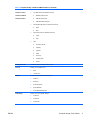
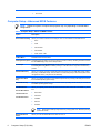
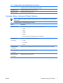
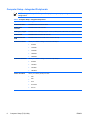
Computer Setup (F10) Utility Guide - dx2250
Microtower Model
HP Compaq Business PC
© Copyright 2006, 2007 Hewlett-Packard
Development Company, L.P. The
information contained herein is subject to
change without notice.
Microsoft, Windows, and Windows Vista are
either trademarks or registered trademarks
of Microsoft Corporation in the United States
and/or other countries.
The only warranties for HP products and
services are set forth in the express warranty
statements accompanying such products
and services. Nothing herein should be
construed as constituting an additional
warranty. HP shall not be liable for technical
or editorial errors or omissions contained
herein.
This document contains proprietary
information that is protected by copyright. No
part of this document may be photocopied,
reproduced, or translated to another
language without the prior written consent of
Hewlett-Packard Company.
Computer Setup (F10) Utility Guide
HP Compaq Business PC
dx2250 Microtower Model
First Edition (November 2006)
Second Edition (January 2007)
Document Part Number: 437300-002
About This Book
This guide provides instructions on how to use Computer Setup. This tool is used to reconfigure and
modify computer default settings when new hardware is installed and for maintenance purposes.
WARNING! Text set off in this manner indicates that failure to follow directions could result in
bodily harm or loss of life.
CAUTION: Text set off in this manner indicates that failure to follow directions could result in
damage to equipment or loss of information.
NOTE:
ENWW
Text set off in this manner provides important supplemental information.
iii
iv
About This Book
ENWW
Table of contents
Computer Setup (F10) Utility
Computer Setup (F10) Utilities ............................................................................................................. 1
Using Computer Setup (F10) Utilities .................................................................................. 1
Computer Setup—System Information ................................................................................ 3
Computer Setup—Standard CMOS Features ..................................................................... 4
Computer Setup—Advanced BIOS Features ...................................................................... 6
Computer Setup—Advanced Chipset Features ................................................................... 7
Computer Setup—Integrated Peripherals ............................................................................ 8
Computer Setup—Power Management Setup .................................................................... 9
Computer Setup—PC Health Status ................................................................................. 10
Computer Setup—(Action Choices) ................................................................................... 10
Recovering the Configuration Settings ............................................................................................... 11
Backing Up the CMOS ....................................................................................................... 11
Restoring the CMOS .......................................................................................................... 11
ENWW
v
vi
ENWW
Computer Setup (F10) Utility
Computer Setup (F10) Utilities
Use Computer Setup (F10) Utility to do the following:
●
Change factory default settings.
●
Set the system date and time.
●
Set, view, change, or verify the system configuration, including settings for processor, graphics,
memory, audio, storage, communications, and input devices.
●
Modify the boot order of bootable devices such as hard drives, diskette drives, optical drives, or
USB flash media devices.
●
Restrict a device from booting the unit.
●
Run hard drive self-tests.
●
View CPU and system temperatures.
●
Enter the Asset Tag or property identification number assigned by the company to this computer.
●
Establish a supervisor password that controls access to Computer Setup (F10) Utility and the
settings described in this section.
●
Secure integrated I/O functionality, including the serial, USB, or parallel ports, audio, or embedded
NIC, so that they cannot be used until they are unsecured.
●
Enable or disable removable media boot ability.
●
Enable or disable legacy diskette write ability (when supported by hardware).
Using Computer Setup (F10) Utilities
Computer Setup can be accessed only by turning the computer on or restarting the system. To access
the Computer Setup Utilities menu, complete the following steps:
1.
Turn on or restart the computer.
2.
As soon as the computer is turned on, press F10 when the monitor light turns green to enter
Computer Setup. Press Enter to bypass the title screen, if necessary.
NOTE: If you do not press F10 at the appropriate time, you must restart the computer and
again press F10 when the monitor light turns green to access the utility.
3.
ENWW
The Computer Setup Utility screen is divided into menu headings and actions.
Computer Setup (F10) Utilities
1
Eight menu headings appear on the Computer Setup Utility screen:
●
System Information
●
Standard CMOS Features
●
Advanced BIOS Features
●
Advanced Chipset Features
●
Integrated Peripherals
●
Power Management Setup
●
PC Health Status
Five action choices are listed on the Computer Setup Utility screen:
●
Load Optimized Defaults
●
Set Supervisor Password
●
Set User Password
●
Save & Exit Setup
●
Exit Without Saving
Use the arrow keys to select the appropriate heading, then press Enter. Use the arrow (up and
down) keys to select the option you want, then press Enter. To return to the previous screen,
press Esc.
4.
To apply and save changes, press F10 or select Save & Exit Setup on the Computer Setup Utility
screen and press Enter.
If you have made changes that you do not want applied, select Exit Without Saving and press
Enter.
CAUTION: Do NOT turn the computer power OFF while the ROM is saving the Computer Setup
(F10) changes because the CMOS could become corrupted. It is safe to turn off the computer
only after exiting the F10 Setup screen.
Table 1 Computer Setup (F10) Utility Main Menu
2
Heading
Table
System Information
Table 2 Computer Setup—System Information on page 3
Standard CMOS Features
Table 3 Computer Setup—Standard CMOS Features
on page 4
Advanced BIOS Features
Table 4 Computer Setup—Advanced BIOS Features
on page 6
Advanced Chipset Features
Table 5 Computer Setup—Advanced Chipset Features
on page 7
Integrated Peripherals
Table 6 Computer Setup—Integrated Peripherals
on page 8
Power Management Setup
Table 7 Computer Setup—Power Management Setup
on page 9
Computer Setup (F10) Utility
ENWW
Table 1 Computer Setup (F10) Utility Main Menu (continued)
PC Health Status
Table 8 Computer Setup—PC Health Status on page 10
(Action Choices)
Table 9 Computer Setup—(Action Choices) on page 10
Computer Setup—System Information
NOTE: Support for specific Computer Setup options may vary depending on the hardware
configuration.
Table 2 Computer Setup—System Information
ENWW
Option
Description
Product Name
(view only)
SKU Number
(view only)
Processor Type
(view only)
Processor Speed
(view only)
Cache Size
(view only)
Memory Size
(view only)
System ROM
(view only)
Integrated MAC
(view only)
UUID
(view only)
System Serial #
(view only)
Asset Tracking
Number
(view only)
Enter Asset Tag No.
Enter asset tag number assigned by the company (maximum 18 characters).
Computer Setup (F10) Utilities
3
Computer Setup—Standard CMOS Features
NOTE: Support for specific Computer Setup options may vary depending on the hardware
configuration.
Table 3 Computer Setup—Standard CMOS Features
Option
Description
Date (mm:dd:yy)
Allows you to set system date.
Time (hh:mm:ss)
Allows you to set system time.
PATA Controller
Disables/enables PATA Controller.
PATA Ch 0 Master
For each, if PATA HDD is used, allows you to:
PATA Ch 0 Slave
●
●
●
●
4
run HDD self-test for selected channel:
●
SMART Status Check
●
HDD Short Self-Test
●
HDD Extended Self-Test
set PATA Ch 0 Master/Slave device details on selected channel to:
●
None
●
Auto
●
Manual
set access mode on selected channel to:
●
CHS (Cylinder-Head-Sector)
●
LBA (Logical Block Addressing)
●
Large
●
Auto
view:
●
Firmware Version
●
Capacity
●
Cylinder
●
Head
●
Precomp
●
Landing Zone
●
Sector
SATA Controller
Disables/enables onboard SATA controller.
SATA Mode
Allows you to set the onboard SATA mode to:
●
Native IDE
●
Legacy IDE
Computer Setup (F10) Utility
ENWW
Table 3 Computer Setup—Standard CMOS Features (continued)
SATA Ch 1 Master
For each, allows you to:
SATA Ch 1 Slave
●
SATA Ch 2 Master
●
SMART Status Check
SATA Ch 2 Slave
●
HDD Short Self-Test
●
HDD Extended Self-Test
●
●
●
set extended IDE drive on selected channel to:
●
None
●
Auto
set access mode on selected channel to:
●
Large
●
Auto
view:
●
Firmware Version
●
Capacity
●
Cylinder
●
Head
●
Precomp
●
Landing Zone
●
Sector
Floppy Controller
Disables/enables the floppy disk controller.
Drive A
Allows you to set Drive A to:
Halt On
POST Delay
ENWW
run HDD self-test for selected channel:
●
None
●
1.44M, 3.5 in.
Allows you to set POST error behavior to:
●
All Errors
●
No Errors
●
All but Keyboard
●
All but Diskette
●
All but Diskette/Keyboard
Allows you to set a POST delay to:
●
0 seconds
●
5 seconds
●
10 seconds
Computer Setup (F10) Utilities
5
●
15 seconds
●
30 seconds
Computer Setup—Advanced BIOS Features
NOTE: Support for specific Computer Setup options may vary depending on the hardware
configuration.
Table 4 Computer Setup—Advanced BIOS Features
Option
Description
Device Boot Disabling
Allows you to restrict a device from booting the unit. You can disable as a bootable device:
●
None
●
USB
●
Internal ODD
●
Internal FDD
●
USB + ODD + FDD
F9 Boot Menu
Disables/enables F9 Boot Menu.
Factory Recovery Boot
Disables/enables the ability to boot to the Recovery partition at startup. Enabling this feature will add
the <F11>Recovery prompt to the startup window.
F11 Prompt
Disables/enables the <F11>Recovery prompt at startup. However, if this feature is disabled and
the Factory Recovery Boot is enabled, pressing F11 will still boot the computer to the Recovery
partition.
Hard Disk Boot Seq.
Allows you to specify the order of attached hard drive devices (such as USB HDD storage, USB2
Drive Key, or USB flash media). The first drive in the order has priority in the boot sequence and is
recognized as drive C (if any devices are attached).
Optical Drive Boot
Seq.
Allows you to specify the order in which attached optical drives (including USB ODD) are checked
for a bootable operating system image.
Network Boot Seq.
Allows you to specify the order in which network devices (including UP NIC cards) are checked for
a bootable operating system image.
First Boot Device
Allows you to specify which devices will boot first, second, third, and fourth or to disable any of the
four:
Second Boot Device
Third Boot Device
Fourth Boot Device
●
Removable
●
Hard Disk
●
CDROM
●
Network
●
Disabled
NOTE: MS-DOS drive lettering assignments may not apply after a non-MS-DOS operating
system has started.
Boot Up NumLock
Status
6
Allows you to set the default NumLock status to off or on.
Computer Setup (F10) Utility
ENWW
Table 4 Computer Setup—Advanced BIOS Features (continued)
Security Option
Allows you to set the security option to Setup or System so that the password is required every time
the system boots or only when entering Computer Setup.
BIOS Write Protect
Disables/enables BIOS Write Protect function.
AMD NX Function
Disables/enables AMD NX Function.
Computer Setup—Advanced Chipset Features
NOTE: Support for specific Computer Setup options may vary depending on the hardware
configuration.
Table 5 Computer Setup—Advanced Chipset Features
Option
Description
UMA Frame Buffer
Select the UMA (Unified Memory Architecture) frame buffer size:
●
32MB
●
64MB
●
128MB
●
256MB
●
Recommended (system allocates memory automatically)
Init Display First
Allows you to select the primary display device:
(VGA Setting)
●
PCI Slot
●
OnChipVGA
●
PCIEx
SURROUNDVIEW
Disables/enables SURROUNDVIEW (available when an ATI PCIEx video card is installed).
(VGA Setting)
Auto Detect PCI Clk
Disables/enables PCI clock auto-detection.
(VGA Setting)
Spread Spectrum
Disables/enables Spread Spectrum.
(VGA Setting)
ENWW
Computer Setup (F10) Utilities
7
Computer Setup—Integrated Peripherals
NOTE: Support for specific Computer Setup options may vary depending on the hardware
configuration.
Table 6 Computer Setup—Integrated Peripherals
Option
Heading
Onboard HD Audio
Disables/enables onboard HD audio.
OnChip USB
Controller
Disables/enables USB controller.
USB Legacy Support
Disables/enables USB legacy support function (USB keyboard, USB mouse, and USB flash media).
Onboard LAN
Disables/enables onboard LAN controller.
Onboard LAN Boot
ROM
Disables/enables the boot ROM of the onboard LAN chip.
Onboard Serial Port
Allows you to select a setting for the onboard serial port:
Onboard Parallel Port
Parallel Port Mode
8
●
Disabled
●
3F8/IRQ4
●
2F8/IRQ3
●
3E8/IRQ4
●
2E8/IRQ3
Allows you to select a setting for the onboard parallel port:
●
Disabled
●
378/IRQ7
●
278/IRQ5
●
3BC/IRQ7
Allows you to select parallel port mode:
●
SPP
●
EPP
●
ECP
●
ECP+EPP
●
Normal
Computer Setup (F10) Utility
ENWW
Computer Setup—Power Management Setup
NOTE: Support for specific Computer Setup options may vary depending on the hardware
configuration.
Table 7 Computer Setup—Power Management Setup
ENWW
Option
Heading
After AC Power Loss
Allows you to select system power loss behavior:
●
On
●
Off
●
Last State
External Modem S5
Wake-Up
Disables/enables wake-up modem from S5.
Wake on PCI Device
from S5
Disables/enables PCI S5 on power on.
AMD Cool'n'Quiet
Disables/enables the AMD Cool'n'Quiet feature.
HPET Support
Disables/enables HPET (high precision event timer). This feature can be disabled if it causes a
resource conflict in the OS.
RTC Alarm Resume
Disables/enables RTC (real-time clock) alarm.
Date (of Month)
If RTC Alarm Resume is enabled, allows you to select the day of the month for resumption of RTC
alarm. (Set to 0 for every day.)
Resume Time
(hh:mm:ss)
If RTC Alarm Resume is enabled, allows you to select what time the RTC alarm will resume.
Computer Setup (F10) Utilities
9
Computer Setup—PC Health Status
NOTE: Support for specific Computer Setup options may vary depending on the hardware
configuration.
Table 8 Computer Setup—PC Health Status
Option
Description
System Fan Fail Check
Disables/enables system fan detection during POST.
Smart Fan Function
Disables/enables smart fan functionality.
Current CPU
Temperature
(view only)
Current System
Temperature
(view only)
Current CPU Fan
Speed
(view only)
Current System Fan
Speed
(view only)
Vcore
(view only)
+12V
(view only)
VCC5
(view only)
+3.3V
(view only)
VBAT (V)
(view only)
3VSB (V)
(view only)
Computer Setup—(Action Choices)
NOTE: Support for specific Computer Setup options may vary depending on the hardware
configuration.
Table 9 Computer Setup—(Action Choices)
10
Option
Description
Load Optimized
Defaults
Allows you to reset Computer Setup to factory defaults.
Set Supervisor
Password
Allows you to establish a password to control access to Computer Setup.
Set User Password
Allows you to establish a password to control access to the computer. (Supervisor password must
be set before you can set a User password.)
Save & Exit Setup
Allows you to save current settings and exit Computer Setup.
Exit Without Saving
Allows you to exit Computer Setup without saving changes.
Computer Setup (F10) Utility
ENWW
Recovering the Configuration Settings
Recovering the configuration settings established in the Computer Setup (F10) Utility requires that you
first back up the settings before a recovery is needed.
The CMOS Save/Load utility can be found at http://www.hp.com under the Software & Driver Downloads
for your specific model. Download the firmware files into a folder on a removable storage device. It is
recommended that you save any modified computer configuration settings to a diskette, a USB flash
media device, or a diskette-like device (a storage device set to emulate a diskette drive) and save the
diskette or device for possible future use.
Backing Up the CMOS
1.
Make sure the computer to be backed up is turned on. Connect the removable storage to the
computer.
2.
Boot to DOS.
3.
Type N:\folder\BIOS.exe SAVE:ABC001.DAT (where N is the drive letter of the removable
storage) to save the CMOS setting to the removable storage device.
Restoring the CMOS
ENWW
1.
Make sure the target computer is turned on. Connect the removable storage to the target computer.
2.
Boot to DOS.
3.
Type N:\folder\BIOS.exe LOAD:ABC001.DAT (where N is the drive letter of the removable
storage) to load the custom CMOS setting onto the target system.
Recovering the Configuration Settings
11