1
INTERCOM
MIC ON
INTERCOM
MIC ON
LEVEL
HIGH
MED
LOW
PUSH TO TALK
PUSH TO TALK
HELP
DESK
ROOM
101
LAB
ADMIN
OFFICE
1
2
3
4
HELP
DESK
SECURITY
LAB
ADMIN
OFFICE
1
2
3
4
IPI 104
IPI 204
LEVEL
INTERCOM
MIC ON
INTERCOM
MIC ON
LEVEL
HIGH
MED
LOW
PUSH TO
TALK
LEVEL
HELP
DESK
PUSH TO
TALK
IPI 201
HELP
DESK
IPI 101
IPI 100 and IPI 200 Series
MediaLink™ IP Intercom™ Interfaces
68-1170-01
Rev. D 09 09
Precautions
Safety Instructions • English
Warning
This symbol is intended to alert the user of important operating and maintenance
(servicing) instructions in the literature provided with the equipment.
Power sources • This equipment should be operated only from the power source indicated on the product. This
equipment is intended to be used with a main power system with a grounded (neutral) conductor. The
third (grounding) pin is a safety feature, do not attempt to bypass or disable it.
This symbol is intended to alert the user of the presence of uninsulated dangerous
voltage within the product’s enclosure that may present a risk of electric shock.
Power disconnection • To remove power from the equipment safely, remove all power cords from the rear of
the equipment, or the desktop power module (if detachable), or from the power source receptacle (wall
plug).
Caution
Read Instructions • Read and understand all safety and operating instructions before using the equipment.
Retain Instructions • The safety instructions should be kept for future reference.
Follow Warnings • Follow all warnings and instructions marked on the equipment or in the user
information.
Avoid Attachments • Do not use tools or attachments that are not recommended by the equipment
manufacturer because they may be hazardous.
Consignes de Sécurité • Français
Power cord protection • Power cords should be routed so that they are not likely to be stepped on or pinched by
items placed upon or against them.
Servicing • Refer all servicing to qualified service personnel. There are no user-serviceable parts inside. To
prevent the risk of shock, do not attempt to service this equipment yourself because opening or removing
covers may expose you to dangerous voltage or other hazards.
Slots and openings • If the equipment has slots or holes in the enclosure, these are provided to prevent
overheating of sensitive components inside. These openings must never be blocked by other objects.
Lithium battery • There is a danger of explosion if battery is incorrectly replaced. Replace it only with the
same or equivalent type recommended by the manufacturer. Dispose of used batteries according to the
manufacturer’s instructions.
Avertissement
Ce symbole sert à avertir l’utilisateur que la documentation fournie avec le matériel
contient des instructions importantes concernant l’exploitation et la maintenance
(réparation).
Alimentations• Ne faire fonctionner ce matériel qu’avec la source d’alimentation indiquée sur l’appareil. Ce
matériel doit être utilisé avec une alimentation principale comportant un fil de terre (neutre). Le troisième
contact (de mise à la terre) constitue un dispositif de sécurité : n’essayez pas de la contourner ni de la
désactiver.
Ce symbole sert à avertir l’utilisateur de la présence dans le boîtier de l’appareil
de tensions dangereuses non isolées posant des risques d’électrocution.
Déconnexion de l’alimentation• Pour mettre le matériel hors tension sans danger, déconnectez tous les cordons
d’alimentation de l’arrière de l’appareil ou du module d’alimentation de bureau (s’il est amovible) ou
encore de la prise secteur.
Attention
Lire les instructions• Prendre connaissance de toutes les consignes de sécurité et d’exploitation avant
d’utiliser le matériel.
Conserver les instructions• Ranger les consignes de sécurité afin de pouvoir les consulter à l’avenir.
Respecter les avertissements • Observer tous les avertissements et consignes marqués sur le matériel ou
présentés dans la documentation utilisateur.
Eviter les pièces de fixation • Ne pas utiliser de pièces de fixation ni d’outils non recommandés par le
fabricant du matériel car cela risquerait de poser certains dangers.
Protection du cordon d’alimentation • Acheminer les cordons d’alimentation de manière à ce que personne ne
risque de marcher dessus et à ce qu’ils ne soient pas écrasés ou pincés par des objets.
Réparation-maintenance • Faire exécuter toutes les interventions de réparation-maintenance par un technicien
qualifié. Aucun des éléments internes ne peut être réparé par l’utilisateur. Afin d’éviter tout danger
d’électrocution, l’utilisateur ne doit pas essayer de procéder lui-même à ces opérations car l’ouverture ou le
retrait des couvercles risquent de l’exposer à de hautes tensions et autres dangers.
Fentes et orifices • Si le boîtier de l’appareil comporte des fentes ou des orifices, ceux-ci servent à empêcher
les composants internes sensibles de surchauffer. Ces ouvertures ne doivent jamais être bloquées par des
objets.
Lithium Batterie • Il a danger d’explosion s’ll y a remplacment incorrect de la batterie. Remplacer uniquement
avec une batterie du meme type ou d’un ype equivalent recommande par le constructeur. Mettre au reut les
batteries usagees conformement aux instructions du fabricant.
Sicherheitsanleitungen • Deutsch
Vorsicht
Dieses Symbol soll dem Benutzer in der im Lieferumfang enthaltenen
Dokumentation besonders wichtige Hinweise zur Bedienung und Wartung
(Instandhaltung) geben.
Stromquellen • Dieses Gerät sollte nur über die auf dem Produkt angegebene Stromquelle betrieben werden.
Dieses Gerät wurde für eine Verwendung mit einer Hauptstromleitung mit einem geerdeten (neutralen)
Leiter konzipiert. Der dritte Kontakt ist für einen Erdanschluß, und stellt eine Sicherheitsfunktion dar. Diese
sollte nicht umgangen oder außer Betrieb gesetzt werden.
Dieses Symbol soll den Benutzer darauf aufmerksam machen, daß im Inneren des
Gehäuses dieses Produktes gefährliche Spannungen, die nicht isoliert sind und
die einen elektrischen Schock verursachen können, herrschen.
Stromunterbrechung • Um das Gerät auf sichere Weise vom Netz zu trennen, sollten Sie alle Netzkabel
aus der Rückseite des Gerätes, aus der externen Stomversorgung (falls dies möglich ist) oder aus der
Wandsteckdose ziehen.
Achtung
Lesen der Anleitungen • Bevor Sie das Gerät zum ersten Mal verwenden, sollten Sie alle Sicherheits-und
Bedienungsanleitungen genau durchlesen und verstehen.
Aufbewahren der Anleitungen • Die Hinweise zur elektrischen Sicherheit des Produktes sollten Sie
aufbewahren, damit Sie im Bedarfsfall darauf zurückgreifen können.
Befolgen der Warnhinweise • Befolgen Sie alle Warnhinweise und Anleitungen auf dem Gerät oder in der
Benutzerdokumentation.
Keine Zusatzgeräte • Verwenden Sie keine Werkzeuge oder Zusatzgeräte, die nicht ausdrücklich vom
Hersteller empfohlen wurden, da diese eine Gefahrenquelle darstellen können.
Instrucciones de seguridad • Español
Schutz des Netzkabels • Netzkabel sollten stets so verlegt werden, daß sie nicht im Weg liegen und niemand
darauf treten kann oder Objekte darauf- oder unmittelbar dagegengestellt werden können.
Wartung • Alle Wartungsmaßnahmen sollten nur von qualifiziertem Servicepersonal durchgeführt werden.
Die internen Komponenten des Gerätes sind wartungsfrei. Zur Vermeidung eines elektrischen Schocks
versuchen Sie in keinem Fall, dieses Gerät selbst öffnen, da beim Entfernen der Abdeckungen die Gefahr
eines elektrischen Schlags und/oder andere Gefahren bestehen.
Schlitze und Öffnungen • Wenn das Gerät Schlitze oder Löcher im Gehäuse aufweist, dienen diese zur
Vermeidung einer Überhitzung der empfindlichen Teile im Inneren. Diese Öffnungen dürfen niemals von
anderen Objekten blockiert werden.
Litium-Batterie • Explosionsgefahr, falls die Batterie nicht richtig ersetzt wird. Ersetzen Sie verbrauchte
Batterien nur durch den gleichen oder einen vergleichbaren Batterietyp, der auch vom Hersteller
empfohlen wird. Entsorgen Sie verbrauchte Batterien bitte gemäß den Herstelleranweisungen.
Advertencia
Este símbolo se utiliza para advertir al usuario sobre instrucciones importantes
de operación y mantenimiento (o cambio de partes) que se desean destacar en el
contenido de la documentación suministrada con los equipos.
Alimentación eléctrica • Este equipo debe conectarse únicamente a la fuente/tipo de alimentación eléctrica
indicada en el mismo. La alimentación eléctrica de este equipo debe provenir de un sistema de distribución
general con conductor neutro a tierra. La tercera pata (puesta a tierra) es una medida de seguridad, no
puentearia ni eliminaria.
Este símbolo se utiliza para advertir al usuario sobre la presencia de elementos con
voltaje peligroso sin protección aislante, que puedan encontrarse dentro de la caja
o alojamiento del producto, y que puedan representar riesgo de electrocución.
Desconexión de alimentación eléctrica • Para desconectar con seguridad la acometida de alimentación eléctrica
al equipo, desenchufar todos los cables de alimentación en el panel trasero del equipo, o desenchufar el
módulo de alimentación (si fuera independiente), o desenchufar el cable del receptáculo de la pared.
Precaucion
Leer las instrucciones • Leer y analizar todas las instrucciones de operación y seguridad, antes de usar el
equipo.
Conservar las instrucciones • Conservar las instrucciones de seguridad para futura consulta.
Obedecer las advertencias • Todas las advertencias e instrucciones marcadas en el equipo o en la
documentación del usuario, deben ser obedecidas.
Evitar el uso de accesorios • No usar herramientas o accesorios que no sean especificamente recomendados
por el fabricante, ya que podrian implicar riesgos.
安全须知 • 中文
这个符号提示用户该设备用户手册中有重要的操作和维护说明。
这个符号警告用户该设备机壳内有暴露的危险电压,有触电危险。
注意
阅读说明书 • 用户使用该设备前必须阅读并理解所有安全和使用说明。
保存说明书 • 用户应保存安全说明书以备将来使用。
遵守警告 • 用户应遵守产品和用户指南上的所有安全和操作说明。
避免追加 • 不要使用该产品厂商没有推荐的工具或追加设备,以避免危险。
Protección del cables de alimentación • Los cables de alimentación eléctrica se deben instalar en lugares donde
no sean pisados ni apretados por objetos que se puedan apoyar sobre ellos.
Reparaciones/mantenimiento • Solicitar siempre los servicios técnicos de personal calificado. En el interior no
hay partes a las que el usuario deba acceder. Para evitar riesgo de electrocución, no intentar personalmente
la reparación/mantenimiento de este equipo, ya que al abrir o extraer las tapas puede quedar expuesto a
voltajes peligrosos u otros riesgos.
Ranuras y aberturas • Si el equipo posee ranuras o orificios en su caja/alojamiento, es para evitar el
sobrecalientamiento de componentes internos sensibles. Estas aberturas nunca se deben obstruir con otros
objetos.
Batería de litio • Existe riesgo de explosión si esta batería se coloca en la posición incorrecta. Cambiar esta
batería únicamente con el mismo tipo (o su equivalente) recomendado por el fabricante. Desachar las
baterías usadas siguiendo las instrucciones del fabricante.
警告
电源 • 该设备只能使用产品上标明的电源。 设备必须使用有地线的供电系统供电。 第三条线(
地线)是安全设施,不能不用或跳过 。
拔掉电源 • 为安全地从设备拔掉电源,请拔掉所有设备后或桌面电源的电源线,或任何接到市电
系统的电源线。
电源线保护 • 妥善布线, 避免被踩踏,或重物挤压。
维护 • 所有维修必须由认证的维修人员进行。 设备内部没有用户可以更换的零件。为避免出现触
电危险不要自己试图打开设备盖子维修该设备。
通风孔 • 有些设备机壳上有通风槽或孔,它们是用来防止机内敏感元件过热。 不要用任何东西
挡住通风孔。
锂电池 • 不正确的更换电池会有爆炸的危险。必须使用与厂家推荐的相同或相近型号的电池。按
照生产厂的建议处理废弃电池。
FCC Class A Notice
This equipment has been tested and found to comply with the limits for a Class A digital device, pursuant to part 15 of the FCC Rules. Operation is subject to
the following two conditions: (1) this device may not cause harmful interference, and (2) this device must accept any interference received, including interference
that may cause undesired operation. The Class A limits are designed to provide reasonable protection against harmful interference when the equipment is
operated in a commercial environment. This equipment generates, uses, and can radiate radio frequency energy and, if not installed and used in accordance with
the instruction manual, may cause harmful interference to radio communications. Operation of this equipment in a residential area is likely to cause harmful
interference, in which case the user will be required to correct the interference at his own expense.
N
This unit was tested with shielded cables on the peripheral devices. Shielded cables must be used with the unit to ensure compliance with FCC emissions limits.
Table of Contents
Chapter One • Before you get Started ............................................................................. 1-1
About this Manual..................................................................................................................... 1-2
Terms and symbols used in this manual................................................................................. 1-2
Additional reference material................................................................................................. 1-3
About the IP Intercom Modules. ....................................................................................... 1-3
Security features........................................................................................................................ 1-4
Features. ........................................................................................................................................... 1-4
System Requirements.............................................................................................................. 1-5
UL Requirements......................................................................................................................... 1-5
Chapter Two • Installation. ......................................................................................................... 2-1
IPI Rear Panel Features and Cabling. .............................................................................. 2-2
MLC Audio Connection............................................................................................................ 2-4
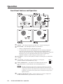
Sample Applications................................................................................................................. 2-5
Single PC to panel...................................................................................................................... 2-5
Multiple PCs to panel................................................................................................................ 2-6
Panel-to-panel mode................................................................................................................. 2-7
Server mode................................................................................................................................ 2-8
Intercom with amplifier............................................................................................................ 2-9
Chapter Three • Operation.......................................................................................................... 3-1
Front Panel Features and Operation............................................................................... 3-2
Button Operation........................................................................................................................ 3-3
Push to talk operation.............................................................................................................. 3-3
Indication (lighting). ................................................................................................................. 3-3
Chapter Four • Initial Configuration. ................................................................................. 4-1
Before you Begin. ....................................................................................................................... 4-2
Setting the IP address using Global Configurator................................................. 4-3
Setting the IP address using embedded Web pages. ........................................... 4-4
Setting the IP address using the ARP command..................................................... 4-6
Chapter Five • HelpDesk Software....................................................................................... 5-1
Introduction to the Software.............................................................................................. 5-2
System Requirements.............................................................................................................. 5-2
Installing the Software........................................................................................................... 5-2
Starting the Program. .............................................................................................................. 5-3
IPI 100 and IPI 200 Series • Table of Contents
i
Table of Contents, cont’d
Configuring the IP Intercom System.............................................................................. 5-5
Basic Configuration................................................................................................................... 5-5
Using the Configuration Utility........................................................................................... 5-5
Importing a GC2/GCZ file..................................................................................................... 5-6
Entering an IP address manually......................................................................................... 5-6
Scanning the local subnet.................................................................................................... 5-7
Configuring an IP device with the configuration utility.................................................... 5-8
Talk mode. .................................................................................................................................. 5-9
Listen mode.............................................................................................................................. 5-10
Group announcement............................................................................................................. 5-11
Loading a pre-recorded .wav file.......................................................................................... 5-12
Changing the default .wav file for intercom events.......................................................... 5-12
Call forwarding........................................................................................................................ 5-13
Setting up a peer-to-peer network................................................................................... 5-13
Setting up one PC as a server............................................................................................ 5-14
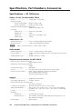
Appendix A • Specifications, Part Numbers, Accessories................................. A-1
Specifications — IPI 100 Series.......................................................................................... A-2
Included Parts (IPI 100 Series)............................................................................................ A-3
Accessories (IPI 100 Series).................................................................................................. A-3
Specifications — IPI 200 Series.......................................................................................... A-4
Included Parts (IPI 200 Series)............................................................................................ A-7
Accessories (IPI 200 Series).................................................................................................. A-7
Appendix B • SIS Programming and Control..............................................................B-1
Host-to-IPI Communications. ...............................................................................................B-2
IPI-initiated Messages..............................................................................................................B-2
Password information...............................................................................................................B-3
Error responses...........................................................................................................................B-3
Error response references.........................................................................................................B-3
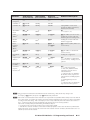
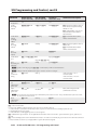
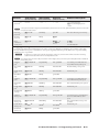
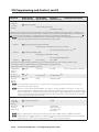
Commands and Reponses......................................................................................................B-4
Using the command/response table. ......................................................................................B-4
Symbol definitions.....................................................................................................................B-5
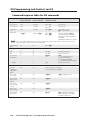
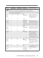
Command/response table for SIS commands. ..........................................................B-8
ii
IPI 100 and IPI 200 Series • Table of Contents
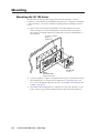
Appendix C • Mounting.................................................................................................................C-1
Mounting the IPI 100 Series.................................................................................................C-2
Mounting the IPI 200 Series.................................................................................................C-3
Appendix D • Button Labels. .................................................................................................... D-1
Installing or Replacing Button Labels........................................................................... D-2
Button Label Generator software.......................................................................................... D-2
Installing the Button-Label Generator software.................................................................. D-2
Using the Button-Label Generator software........................................................................ D-3
Installing Button Labels........................................................................................................... D-4
All trademarks mentioned in this manual are the properties of their respective owners.
68-1170-01
Rev. D
09 09
IPI 100 and IPI 200 Series • Table of Contents
iii
Table of Contents, cont’d
iv
IPI 100 and IPI 200 Series • Table of Contents
IPI 100 and IPI 200 Series
1
Chapter One
Before you get Started
About This Manual
About the IP Intercom Modules
Features
System Requirements
UL Requirements
Preface
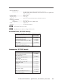
About this Manual
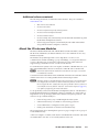
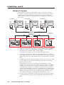
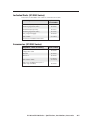
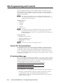
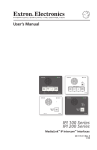
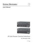
This manual describes how to configure and operate the following Extron
MediaLink™ IP Intercom® Modules:
•
IPI 101 AAP
•
IPI 104 AAP
•
IPI 201 Series
•
IPI 204 Series
N The IPI 201 and IPI 204 series include AAP and 2-gang version intercoms.
Terms and symbols used in this manual
The following terms are used throughout the manual and carry the following
meanings:
•
The terms “IPI” and “intercom” are used interchangeably in this manual
to refer to all models.
•
The term “100 Series” refers to both the IPI 101 and IPI 104.
•
The term “200 Series” refers to both the IPI 201 models (AAP or 2‑gang
version) and both the IPI 204 models.
•
The term “console” refers to a PC that is running the IP Intercom
HelpDesk™ software and is connected to one or more IPI Intercom
Systems (MLC 226 IP with IPI 104/101 AAP or stand-alone IPI 201/204
AAP or 2‑gang models) via a local area network. •
“MLC” refers to an MLC 226 IP MediaLink Controller.
•
“WAV” refers to a Waveform audio file, which has a “.wav” file
extension.
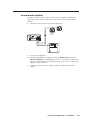
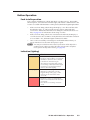
The following symbols are used in this manual and have the following meanings:
N A Note icon draws attention to important information.
C
T
A Tip provides a suggestion to make setting up or working with the device easier.
W
D
I
1-2
A Caution icon warns of things that might damage the equipment.
A Warning icon warns of things that might cause injury, death, or other
severe consequences.
A Dangerous icon is intended to alert the user of the presence of
uninsulated dangerous voltage within the product’s enclosure that may
present a risk of electric shock.
A Important icon warns of important operating and maintenance
(servicing) instructions in the literature provided with the equipment.
IPI 100 and IPI 200 Series • Preface
Additional reference material
The following documents are referred to in this manual. They are available at
www.extron.com.
•
MLC 226 IP User’s Manual
•
IP Intercom brochure
•
IP Intercom System Frequently Asked Questions
•
IP Intercom Network Impact Statement
•
IP Intercom Best Practices
•
IP Intercom Help File (automatically downloaded and installed along with
the IP Intercom HelpDesk software)
•
Global Configurator Help File (automatically downloaded and installed
along with the Global Configurator software)
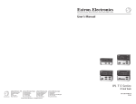
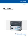
About the IP Intercom Modules
The Extron MediaLink IPI 104 AAP and IPI 204 (four-button modules) and the
IPI 101 AAP and IPI 201 (one-button modules) are for use with Extron’s two-way
IP Intercom System.
The IP Intercom System helps with room-to-help desk or room-to-room
communications within a building, a group of buildings, or even greater distances
as long as the intercoms are part of the same network. It provides enhanced
support using a standard local area or wide area IP network.
For an IP Intercom System, each room requires an IPI 201 or IPI 204 intercom, or an
MLC 226 IP MediaLink Controller connected to an IPI 104 AAP or IPI 101 AAP. N The IPI 201 and IPI 204 are stand-alone units that do not require a connection
to a MediaLink controller.
Connections between the IPI 101 AAP and IPI 104 AAP intercoms with MLC 226 IP
and the network are via existing standard network twisted pair cables.
N The MLC 226 IP to which the IPI 100 Series intercoms are connected must have
been shipped after November 16, 2005 and also have firmware version 1.05 or
later to support the IPI. Examine the rear panel of the MLC 226 IP. If there is a
second RJ-45 connector, labelled “Intercom” and an audio output (see page 2-2),
it is capable of supporting an IP Intercom station.
To set up the IPI you must use the IP Intercom HelpDesk.software. The Windows®based MediaLink IP Intercom HelpDesk software is installed on a central office or
help desk PC to set up, manage, and monitor IP Intercom System operations. The
software also provides the ability for:
•
faster call response by any available help desk in the system
•
enhanced staff use by consolidation of monitoring operations
•
secure administrator configuration and operator log-in
•
making announcements to all intercoms simultaneously
The paging feature allows the help desk operator to page a single room or group of
rooms simultaneously.
A line level output is available on the back of each MediaLink Controller and standalone IPI model to mix into a local sound system in each room.
IPI 100 and IPI 200 Series • Preface
1-3
Preface, cont’d
Security features
The IP Intercom permits real-time audio monitoring by the help desk of any room
where an IPI is installed. Using the IP Intercom HelpDesk software, intercom calls
and pages can be logged and date/time-stamped on the help desk computer. Event
logs can be accessed and archived for record keeping and tracking purposes.
N In some states it is illegal to listen in on rooms. To satisfy legal and privacy
requirements, the intercom can play a recurring tone during room monitoring. This
tone can be turned on or off in the HelpDesk Preferences.
The status monitoring capablities of the MLC 226 IP and the audio monitoring
capabilities of the intercom can be combined to monitor the status of equipment
for each room. GlobalViewer software can be configured to automatically notify a
help desk operator or security personnel via e-mail. Help desk operators or other
authorized personnel can then use the IP Intercom’s audio monitoring capability
to listen to the activity in this room, helping them determine if security personnel
should be dispatched to investigate.
Features
1-4
•
Two-way, half-duplex voice communications over an IP network
•
Compatibility with IP Intercom-enabled MLC 226 IP MediaLink Controllers
(IPI 101 AAP and IPI 104 AAP)
•
Backlit, configurable Push To Talk buttons
•
Integrated speaker and microphone
•
Three-position switch to adjust speaker volume levels (IPI 101 AAP and IPI 104
AAP only)
•
LED indicator to show when the room is being monitored
•
Four space Architectural Adapter Plate (AAP) and 2-gang opening (IPI 200
series only) mounting
•
Connection via existing network cable drops (one drop per MLC-IPI pair,
IPI 101 AAPs and IPI 104 AAPs, only)
IPI 100 and IPI 200 Series • Preface
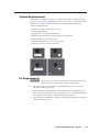
System Requirements
The IP Intercom HelpDesk software is available at no charge via the Extron Web
site (www.extron.com) or the DVD that comes with your IPI. To install and run IP
HelpDesk, you need a PC that meets the following minimum requirements:
• Microsoft® Windows XP
• Pentium® 4, 2 GHz or faster microprocessor
• At least 512 MB RAM
• 500 MB or more available hard disk space
• Windows-supported sound card, microphone, and speakers
• Microsoft Direct X version 9.0c or later
• Microsoft .NET framework, version 2.0 or later
• Network card and a network connection
INTERCOM
INTERCOM
MIC ON
MIC ON
PUSH TO TALK
HELP
DESK
ROOM
101
LAB
ADMIN
OFFICE
1
2
3
4
PUSH TO
TALK
IPI 204
CONFIG
INTERCOM
HELP
DESK
IPI 201
CONFIG
INTERCOM
MIC ON
MIC ON
PUSH TO TALK
HELP
DESK
ROOM
101
LAB
ADMIN
OFFICE
1
2
3
4
CONFIG
Extron
PUSH TO
TALK
IPI 204
HELP
DESK
CONFIG
IPI 204
Extron
IPI 201
UL Requirements
W Installation and service must be performed by authorized personnel only.
This product should be used with a UL approved electrical box.
1. This unit is not to be connected to a centralized DC power source or used
beyond its rated voltage range.
2. The IPI 100 AAP or IPI 200 AAP must be installed in a UL listed junction box.
The UL approved electrical wall box (junction box) is not included with the IPI;
the installer is responsible for obtaining and installing the box.
3. The unit must be installed in accordance with the National Electrical Code and
with local electrical codes.
IPI 100 and IPI 200 Series • Preface
1-5
Preface, cont’d
1-6
IPI 100 and IPI 200 Series • Preface
IPI 100 and IPI 200 Series
2
Chapter Two
Installation
IPI Rear Panel Features and Cabling
MLC Audio Connection
Sample Applications
Installation
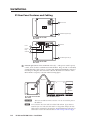
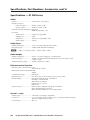
IPI Rear Panel Features and Cabling
1a Intercom Port
2 AAP Mounting Screws (4)
IPI 104 AAP, IPI 101 AAP
Rear Panel
POWER
Power
3
Contact
Relay
4
Audio Out
5
C NO
RELAY
1b LAN Port
AUDIO OUT
LAN
2 AAP Mounting Screws (4)
IPI 204 AAP, IPI 201 AAP
Rear Panel
Ä
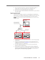
Intercom port (IPI 101 AAP and IPI 104 AAP only) — This port is used for power,
control, and voice data communication with the MLC. Plug one end of a standard,
straight through, CAT 5, CAT 5e, or CAT 6 cable terminated with RJ‑45 connectors
into this port. Plug the other end of the cable into the Intercom connector on the
MLC 226 IP’s rear panel, as shown in the following figure.
<100’ (30.4 m)
INTERCOM
R
HOST
CONTROL
LAN
AUDIO
OUT
1=DIGITAL I/O
2=Tx 3=Rx 5=GND
38400, N, 8, 1
IPI 101 AAP or IPI 104 AAP
Rear Panel
C
PRESS TAB WITH
TWEEKER TO REMOVE
MLC 226 IP Rear Panel
This is not an Ethernet LAN connection. Do not connect these ports to
the Ethernet.
N A 12 inch (30.5 cm) CAT 6 cable is included with each IPI. If you choose to
terminate your own cable, the cable must be no longer than 100 feet (30.4 m).
Cables must be terminated to the T586A or T586B standard and both ends of a
cable must be wired to the same standard (see cable wiring on the next page).
2-2
IPI 100 and IPI 200 Series • Installation
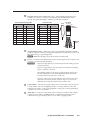
Å
LAN port (IPI 201 AAP and 204 AAP only) — Plug an RJ-45 jack into the LAN
connector to connect to a network. The blinking yellow LED indicates LAN
activity. The green LED lights to indicate a good LAN connection.
Patch (straight-through) cable
Side 1
Pin Wire color
1 White-orange
Side 2
Pin Wire color
1 White-orange
Crossover cable
Side 1
Pin Wire color
1 White-orange
Side 2
Pin Wire color
Side
12345678
Pins
RJ-45
connector
1 White-green
2 Orange
2 Orange
2 Orange
2 Green
3 White-green
3 White-green
3 White-green
3 White-orange
4 Blue
4 Blue
4 Blue
4 Blue
5 White-blue
5 White-blue
5 White-blue
5 White-blue
6 Green
6 Green
6 Green
6 Orange
7 White-brown
7 White-brown
7 White-brown
7 White-brown
8 Brown
8 Brown
8 Brown
8 Brown
12345678
Twisted
Pairs
1&2
b
Clip Down
7&8
3&6 4&5
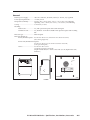
AAP mounting screws — These four screws are permanently attached to the IPI’s
faceplate. They are used for mounting the faceplate into another device (such as an
MLC 226 IP AAP) or a mounting frame.
N Items c to e apply only to the IPI 201 and IPI 204 models.
c
Power — Connect a cable between the 2-pole, 3.5,mm captive screw connector and
a 12 VDC, 1 A power supply (included).
C
The power supply shall not be permanently fixed to the building structure
or similar structures.
The power supply shall not be located within environmental air handling
spaces or within the wall cavity.
The installation shall be in accordance with the applicable provisions of
the National Electrical Code ANSI/NFPA 70, Article 725 and the
Canadian Electrical Code, Part 1, Section 16.
The power supply is to be located within the same vicinity as the Extron
equipment in an ordinary location, Pollution Degree 2, secured to the
equipment rack within the dedicated closet, podium or desk.
d
Contact Relay — The 2-pole, 3.5,mm captive screw contact relay connector is used
to control items such as room lighting, window coverings, and door locks. The
contact may be used to control any equipment as long as the contact specifications
of 24 VDC at 1 A are not exceeded.
e
Audio Out — A 3-pole, 3.5 mm captive screw connector is used for audio output
connection. It provides a -10 dBV balanced or unbalanced signal that can be
connected to local, powered speakers or to any audio or paging system.
IPI 100 and IPI 200 Series • Installation
2-3
Installation, cont’d
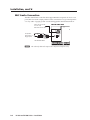
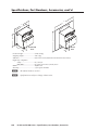
MLC Audio Connection
The MLC 226 IP Series controllers that support IPI intercom panels also have a rear
panel, line level audio output port that can be connected to local, powered speakers
or to any audio or paging system. See the wiring guide in the illustration below.
To/from the IPI 104 AAP
or IPI 101 AAP
Rear Panel Intercom Port
MLC 226 IP Rear Panel
AUDIO
OUT
+
INTERCOM
R
To a Speaker,
Audio System, or
Paging System
Captive Screw
Connector
Do not tin the wires!
N The volume for this audio output can be adjusted via software only.
2-4
IPI 100 and IPI 200 Series • Installation
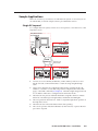
Sample Applications
There are several ways to make use of an IP Intercom System. To see what you can
do with the IPIs, look at the sample scenarios provided in this section.
Single PC to panel
For a simple intercom system, connect one or more panels to a PC that serves as the
help desk console.
Help Desk Console
IP 10.XX.XX.01
Audio
Card
Office
IP 10.XX.XX.04
PROJECTOR
ON
OFF
INTERCOM
AUTO
IMAGE
VCR
DVD
AUX
VIDEO
1
4
2
5
3
6
MIC ON
LEVEL
HIGH
VOLUME
MUTE
MED
LOW
PUSH TO TALK
LAPTOP
IR
PC
HELP
DESK
SECURITY
LAB
ADMIN
OFFICE
1
2
3
4
CONFIG
IPI 104
MLC 226 IP
IPI 104 AAP
TCP/IP
Network
Straight-through
Network Cable
Classroom
IP 10.XX.XX.02
Lab
IP 10.XX.XX.03
PROJECTOR
ON
OFF
INTERCOM
AUTO
IMAGE
VCR
DVD
AUX
VIDEO
1
4
2
5
3
6
MIC ON
PROJECTOR
ON
OFF
INTERCOM
AUTO
IMAGE
LEVEL
VCR
DVD
AUX
VIDEO
1
4
2
5
3
6
MIC ON
LEVEL
HIGH
VOLUME
MUTE
LAPTOP
IR
PC
CONFIG
MED
LOW
PUSH TO
TALK
MUTE
LAPTOP
HELP
DESK
IPI 101
MLC 226 IP
MLC 226 IP AAP
HIGH
VOLUME
IPI 101 AAP
IR
PC
CONFIG
MED
LOW
PUSH TO
TALK
HELP
DESK
IPI 101
MLC 226 IP
MLC 226 IP AAP IPI 101 AAP
1. Connect one or more IPI 201, IPI 204 units, or MLC 226 IP(s) with one or more
IPI 101 AAP and/or IPI 104 AAP units to a network using straight-through
cable.
2. Using a PC in the network, configure the IPI systems, assigning the PC’s IP
address to one button on each IPI, using Global Configurator, the unit’s Web
pages, or the ARP command (see chapter 4). The button light changes from red
to low amber to indicate it is configured and connected to the PC.
3. The intercom user presses and holds the button assigned to the PC to initiate
talk mode. The button glows bright amber, and the Mic On LED lights.
4. The user speaks into the intercom. Audio is output through the PC speakers at
the help desk console.
5. The intercom user releases the button when done speaking.
6. The console operator clicks the Talk button (in the software) or presses the PC’s
space bar to respond.
IPI 100 and IPI 200 Series • Installation
2-5
Installation, cont’d
Multiple PCs to panel
Some facilities may require a system with two or more console PCs. One may
be staffed by a computer applications expert, another by security personnel, and
a third by resource aides or lab stockroom staff. Each console is configured to
connect with several intercoms, and each intercom is configured to contact up to
four consoles.
IP 10.XX.XX.01
IP 10.XX.XX.02
Audio
Card
IP 10.XX.XX.03
Audio
Card
MIS
Help Desk
Campus
Police
Audio
Card
TCP/IP
Network
Classroom
IP 10.XX.XX.04
Classroom
IP 10.XX.XX.05
PROJECTOR
ON
OFF
INTERCOM
AUTO
IMAGE
VCR
DVD
AUX
VIDEO
1
4
2
5
3
6
MONITOR
Chem Lab
Stockroom
Straight-through
Network Cable
Lab
IP 10.XX.XX.06
Office
IP 10.XX.XX.07
IPI 204 AAP
IPI 201 AAP
PROJECTOR
ON
OFF
AUTO
IMAGE
LEVEL
VCR
DVD
1
4
2
5
AUX
VIDEO
HIGH
VOLUME
MUTE
LAPTOP
IR
PC
MED
LOW
PUSH TO
TALK
CONFIG
VOLUME
MUTE
LAPTOP
HELP
DESK
IPI 101
IR
3
6
PC
CONFIG
MLC 226 IP
MLC 226 IP AAP
IPI 101 AAP
MLC 226 IP
MLC 226 IP AAP
IPI 104 AAP
1. Connect one or more PCs to the network and install the IP Intercom HelpDesk
Software on each PC. If call forwarding is used, Extron recommends that no
more than six PCs should be set up for call forwarding.
See chapter 5 for instructions on how to install and use the software.
2. Connect up to a maximum of 250 intercoms (per help desk PC) to a network
using straight-through cable. Extron recommends that large systems should be
segmented, so that no more than 60 intercoms are associated with a single help
desk.
3. Configure the intercoms and set up the intercom list for each console PC. Each
console could be set up to monitor a different group of intercoms, but most
likely the lists will overlap.
In the example shown above, an installation in one building of a college
campus, each room (classroom, lab, or office) contains an intercom. Configure
one button on each intercom to contact the computer help desk. For IPI 104
or IPI 204 models, configure a second button on each intercom to contact the
campus security department. However, only the intercoms located in physical
sciences classrooms and laboratories have a third button configured to contact
the PC console in the lab stockroom. Only the intercoms installed in offices
have a button configured to call the registration department’s console.
4. Once the system is configured, each intercom user presses and holds a button
to initiate talk mode. The button glows bright amber, and the Monitor LED
lights.
2-6
IPI 100 and IPI 200 Series • Installation
5. The user speaks into the intercom. Audio plays through the speakers or
headset at the console the pressed button was configured to call.
6. The intercom user releases the button when done speaking.
7. The console operator clicks the Talk button (in the software) or presses the PC’s
space bar to reply.
Panel-to-panel mode
You do not need to include a console PC as a permanent part of an IP Intercom
System. Here is an example in which panels are configured to “talk” to each other. The software does not need to be running during intercom system operation.
N Panel to panel mode will only work when both panels are in the same network
subnet.
Configuration Console PC
IP 10.XX.XX.01
Connect for configuration.
This connection is not
needed for later operation.
TCP/IP
Network
Straight-through
Network Cable
Classroom
IP 10.XX.XX.02
PROJECTOR
ON
OFF
INTERCOM
AUTO
IMAGE
VCR
DVD
AUX
VIDEO
1
4
2
5
3
6
MIC ON
Lab
IP 10.XX.XX.03
PROJECTOR
ON
OFF
INTERCOM
AUTO
IMAGE
LEVEL
VCR
DVD
AUX
VIDEO
1
4
2
5
3
6
MIC ON
LEVEL
HIGH
VOLUME
MUTE
LAPTOP
IR
PC
CONFIG
MED
LOW
PUSH TO
TALK
HIGH
VOLUME
MUTE
LAPTOP
HELP
DESK
IPI 101
MLC 226 IP
MLC 226 IP AAP IPI 101 AAP
IR
PC
CONFIG
MED
LOW
PUSH TO
TALK
HELP
DESK
IPI 101
MLC 226 IP
MLC 226 IP AAP IPI 101 AAP
1. Connect two IPI 101 AAPs and their MLC 226 IPs to a network using straightthrough cable.
2. Using a PC connected to the same network (as shown in the figure above),
configure the two IPI systems. Read chapter 5 for instructions on how to use
the HelpDesk software for configuration.
3. Close the configuration program. The PC can be disconnected from the
network or used for other functions.
4. Push the button on one IPI to contact the other IPI. On the calling IPI, the
microphone is enabled, the Mic On LED lights, and the button’s light changes
from low amber to bright/high amber. On the IPI being called, the button’s
light changes from low amber to bright/high amber.
IPI 100 and IPI 200 Series • Installation
2-7
Installation, cont’d
Server mode
A single PC can act as a server to control the communication between the intercoms
and the Help Desks. For complete instructions about using the HelpDesk software
to configure a computer as a server or as a client help desk, see chapter 5.
IP 10.XX.XX.01
IP 10.XX.XX.02
Audio
Card
Audio
Card
MIS
Help Desk
IP 10.XX.XX.03
Campus
Police
Audio
Card
Chem Lab
Stockroom
TCP/IP
Network
IP 10.XX.XX.04
Server
TCP/IP
Network
Classroom
IP 10.XX.XX.05
Classroom
IP 10.XX.XX.06
PROJECTOR
ON
OFF
INTERCOM
AUTO
IMAGE
VCR
DVD
AUX
VIDEO
1
4
2
5
3
6
MONITOR
Straight-through
Network Cable
Lab
IP 10.XX.XX.07
Office
IP 10.XX.XX.08
IPI 204 AAP
IPI 201 AAP
PROJECTOR
ON
OFF
AUTO
IMAGE
LEVEL
VCR
DVD
1
4
2
5
AUX
VIDEO
HIGH
VOLUME
MUTE
LAPTOP
IR
PC
CONFIG
MED
LOW
PUSH TO
TALK
VOLUME
MUTE
LAPTOP
HELP
DESK
IPI 101
IR
3
6
PC
CONFIG
MLC 226 IP
MLC 226 IP AAP
IPI 101 AAP
MLC 226 IP
MLC 226 IP AAP
IPI 104 AAP
1. Configure one computer as a server. Ensure that all intercoms are listed in the
intercom list of the server and each Help Desk. Also ensure that all Help Desks in
the system are on the server’s list of Cooperating Help Desks.
2. Configure one of the buttons on each intercom to communicate with the server.
3. Configure all of the Help Desk PCs so that only the server is listed on the list of
Cooperating Help Desks.
4. Set the server to server mode and restart the IPI program on the server.
Any call from an intercom will now be routed by the server to an available Help Desk.
For complete instructions on setting up server and client PCs, see chapter 5, “Setting
up one PC as a server”.
2-8
IPI 100 and IPI 200 Series • Installation
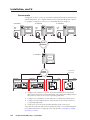
Intercom with amplifier
The MLC’s Audio Out 2-pole captive screw connector outputs a -10 dBV audio
signal that can be routed to an MPA 152 or any external audio amplifier, then to
speakers.
1. Cable the system as shown in the following diagram.
SI 3CT LP
C
US
MPA 152
LISTED
17TT
AUDIO/VIDEO
APPARATUS
12V
3A MAX
4/8
OHMS
L
INPUTS
POWER
Ceiling
Speakers
OUTPUT
CLASS 2 WIRING
DO NOT GROUND
OR SHORT
SPEAKER OUTPUTS!
R
REMOTE
L
R
L
R
10V
VOL/MUTE
50mA
MPA 152
POWER
C NO
RELAY
AUDIO OUT
LAN
IPI 201
2. Power on the equipment.
3. Make fine adjustments to output level using the Remote Line slider in the
Advanced Settings part of the HelpDesk software. The external amplifier (the
MPA 152 in this example) must be adjusted properly to avoid any audio signal
clipping or audio distortion.
4. If desired, use the software to adjust to minimum levels the IPI’s speaker
output.
IPI 100 and IPI 200 Series • Installation
2-9
Installation, cont’d
2-10
IPI 100 and IPI 200 Series • Installation
IPI 100 and IPI 200 Series
3
Chapter Three
Operation
Front Panel Features and Operation
Button Operation
Operation
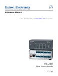
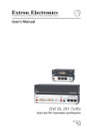
Front Panel Features and Operation
a
b
Speaker — This integrated speaker provides mono output at the IPI panel. Mic On LED — This LED lights under two circumstances:
•
When a configured Push to Talk button is pressed. •
To indicate that someone at the help desk console is listening and that the
intercom is in monitoring mode. Monitoring mode permits hands-free
operation: the user does not have to press the Push to Talk button to speak into
the intercom. It also lets help desk staff monitor what is happening to
determine whether to send security personnel to that room.
c
Microphone — Push one of the butttons and talk. The microphone is behind this
opening.
d
Level switch — This three-position switch lets you change the
speaker’s loudness level (IPI 100 series, only).
LEVEL
e
Push to Talk button(s) — The IPI 101 AAP and IPI 201 units include
one of these buttons, and the IPI 104 AAP and IPI 204 units have
four.
HIGH
MED
LOW
N The MLC and IPI intercoms must be configured (via software) to associate
each button with the IP address of a specific console PC or intercoms. Once
configured, the IPI 101 AAP and IPI 201 can communicate to one location (one
IP address). The IPI 104 AAP and IPI 204 can communicate with up to four
different locations.
f
3-2
Config Port (IPI 200 Series only) — This 2.5 mm port is used to configure the
IPI 201 and IPI 204 and to upload firmware when necessary.
IPI 100 and IPI 200 Series • Operation
Button Operation
Push to talk operation
Press a Push to Talk button to call the help desk or another console. That enables
the microphone, causes the Mic On LED to light, and enables communication to the
location associated with that button. When pressed, the button lights bright amber.
•
If the console PC being called is busy, the IPI plays a .wav file to tell the caller
that the line is busy. A “call received” message appears at the help desk
console PC to indicate that the intercom is calling. For informaton about .wav
files, see page 5-12 for information about using .wav files.
•
If the console PC being called is not connected to the network, the IPI plays a
.wav file stored on its local MLC to notify the intercom user that the connection
is not available. Also, the button lights red instead of amber.
•
Once a call is successfully connected, press and hold the button when you
speak, and release it to allow the other party to speak.
N You must press and hold an IPI’s button to speak and to call the help desk or
another intercom. When you release the button, the intercom’s microphone
turns off unless the help desk is listening (see page 510).
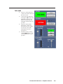
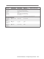
Indication (lighting)
Button Color
Indication
Amber (dim)
• The button is in standby. • The device at the IP address associated with
that button is turned on and is connected
to the network. If that device gets
disconnected or if the help desk software
is not running on that PC, the button lights
red. Once it is reconnected, the button
returns to dim amber lighting.
Amber (bright)
• The IPI is communicating with the location
the button is configured to call. This
happens during a call, a page, or when
receiving an announcement from the
console PC.
Red
• The device (console) associated with the
button is disconnected from the network or
is turned off.
• The software is not running or has been
closed.
IPI 100 and IPI 200 Series • Operation
3-3
Operation
3-4
IPI 100 and IPI 200 Series • Operation
IPI 100 and IPI 200 Series
4
Chapter Four
Initial Configuration
Before you Begin
Setting the IP Address by Global Configurator
Setting the IP Address Using Embedded Web Pages
Setting the IP Address Using the ARP Command
Initial Configuration
The IPI 100 Series units must be connected to a MLC 226 IP MediaLink controller
with a valid IP address. See the MLC 226 IP User’s Manual for information about
configuring the MLC controller’s IP address.
The IPI 200 Series units have a factory default IP address of 192.168.254.254. This
IP address must be changed to an address that will operate on your local network.
There are three ways to change the IP address setting:
• Global Configurator
• IPI 200 Series unit’s embedded Web pages
• Address Resolution Protocol (ARP) command
Before you Begin
1. Obtain a valid IP address for your IPI 200 Series device from your A/V
system’s network administrator.
2.
Write down the unit’s MAC address (a 12-digit number) found on a label on
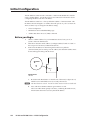
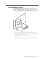
the rear panel of the unit (ex: 00-05-A6-01-0A-74). 3. If the unit’s IP address has been changed from the factory default
(192.168.254.254), before setting a new IP address, the default IP address must
be restored by performing a Mode 4 reset:
RESET
RESET
IPI 200 Series
Left Side
a.
Hold down the Reset button on the left side of the unit (see figure above)
until the Power LED blinks twice (6 seconds), then release.
N The Reset button is recessed. Activate it with an Extron Tweeker or similar tool.
b. Press and release the Reset button again within 1 second.
4-2
The Power LED blinks quickly four times, confirming the Mode 4 reset,
which returns the unit to its factory default IP address.
IPI 100 and IPI 200 Series • Initial Configuration
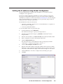
Setting the IP address using Global Configurator
The preferred method for setting a unit’s IP address is to use Extron’s Global
Configurator (GC) application.
If you have Global Configurator installed on a local PC, and have a GC project
file open, proceed with the steps below. If you do not have Global Configurator
installed, it is available as a free download from www.extron.com. The GC help file
steps you through the process of creating a new GC project file, and provides an
illustrated version of the procedure below.
The IPI 200 Series intercom unit must be:
• physically connected to the network or connected directly to a computer via
the front panel Config port.
• at its factory default IP address
To set an IP address with a GC project file open:
1.
From the Edit menu, select Add Device.
The Add Device dialog box opens (see the figure below).
2. Select the appropriate device type (e.g. IPI 204) in the IP Link® Device
drop-down list.
3. Enter the new IP address (ex: 10.14.195.40) in the Name/IP Address field.
4.
Enter a unique device name in the Display Name field.
5. Click the Advanced >>> button.
The Advanced options of the Add Device dialog are displayed, and the
“Advanced >>>” button name changes to “Basic <<<”.
6. Click the Auto Configure IP Address checkbox.
7. Enter the unit’s MAC address in the MAC Address field. The first six digits
(00-05-A6) are pre-populated, and identify this unit as an Extron device. You
only need to enter the final six digits. Dashes between digits are auto-filled.
8.
Click the Set button. The Auto Configure Successful dialog box opens.
9.
Click OK.
IPI 100 and IPI 200 Series • Initial Configuration
4-3
Initial Configuration, cont’d
Setting the IP address using embedded Web pages
Each IPI 200 Series intercom unit contains an on-board Web server with interactive
pages that can be used to configure the device.
The intercom unit must be at its factory default IP address.
To set an IP address via embedded Web pages:
1. Connect an Ethernet crossover cable between the device and a local PC.
2. On the PC, locate the TCP/IP Properties dialog box. On Windows XP, the TCP/IP Properties dialog box is found at:
Start > My Network Places > right-click to Properties > Local Area
Connection > right-click to Properties > Internet Protocol (TCP/IP) >
Properties.
3. Record the current IP address, subnet mask, default gateway and DHCP
settings. You will need this information later to return the PC to its original
TCP/IP settings.
IP Address:
.
Subnet Mask:
.
.
.
.
.
4. Enter the following:
IP address: 192.168.254.253
Subnet mask: 255.255.0.0
Default gateway: <blank>
5. Click OK.
4-4
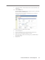
6. Open a Web browser on the local PC.
7. Enter 192.168.254.254 in the browser’s Address field and press the Enter key.
The intercom unit’s embedded Web page is displayed.
8. Click the Configuration tab.
IPI 100 and IPI 200 Series • Initial Configuration
9. Change the IP Address and Subnet Mask fields to the desired IP address and
subnet mask.
10. Click the Submit button.
The new IP address and subnet mask are assigned to the device, and the Web
browser connection is immediately lost.
The device, with its new IP address and subnet mask is now ready to be
connected to your A/V network.
To return the local PC to its original TCP/IP settings:
1. Close the Web browser.
2. Disconnect the Ethernet crossover cable from the PC and the device.
3. Return to the TCP/IP Properties dialog box on the PC.
4. Return the IP address, Subnet mask, Default gateway, and DHCP fields to
their original settings.
5.
Reboot the PC.
IPI 100 and IPI 200 Series • Initial Configuration
4-5
Initial Configuration, cont’d
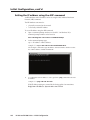
Setting the IP address using the ARP command
An IPI 200 Series unit’s IP address can be set using the DOS Address Resolution
Protocol (ARP) command.
The IPI 200 Series unit must be:
• physically connected to the network
• at its factory default IP address
To set an IP address using the ARP command:
1. Open a command prompt window on a local PC. On Windows XP, a
command prompt window can be found at:
Start > All Programs > Accessories > Command Prompt
2. At the command prompt type:
arp - s <IP address> <MAC address>
example: C:\>arp -s 192.168.254.254 00-05-A6-00-30-5F
The example command assigns IP address 192.168.254.254 to the device that
has a MAC address of 00-05-A6-00-30-5F.
4-6
3.
To confirm the new IP address is active, perform a ping command to the new
IP address.
example: C:\>ping 192.168.254.254
If the IP address setting was successful, the device replies 3 or more times:
Reply from <IP address>: bytes=32 time <1ms TTL=64
IPI 100 and IPI 200 Series • Initial Configuration
IPI 100 and IPI 200 Series
5
Chapter Five
HelpDesk Software
Introduction to the Software
System Requirements
Installing the Software
Starting the Program
Configuring the IPI Intercom System
HelpDesk Software
Introduction to the Software
The IP Intercom System requires a PC running the IP Intercom HelpDesk software
and an IP Intercom unit. The HelpDesk program (provided on the software
disk) has a management and monitoring application (the main screen) and a
configuration utility.
If an IPI 100 series unit is used, it must be linked to an MLC 226 IP controller. The
IPI 200 series are stand-alone units that do not need to be connected to another
MediaLink device.
The PC, the IPI 200 series unit, and the MLC 226 IP, when used with an IPI 100
series unit, must all be connected to the Local Area Network (LAN) and each must
have a unique IP address. Consult with your IT department to ensure that IP
addresses have been correctly allocated.
Network and IT administrators should use information from the following white
papers, which can be found on the Extron Web site (www.extron.com), to ensure
optimal network configuration and compatibility for the IP Intercom system:
•
IP Intercom Network Impact Statement
•
IP Intercom Best Installation Practices
Extron recommends that the IP Intercoms and the HelpDesk be on the same LAN
with a static IP address and not be separated by a firewall. If the IP addresses are
on different subnets, it is best to set up a dedicated VLAN. If a firewall is required,
the following ports need to be open: UDP port 3121 (audio traffic), TCP telnet port
23 (control and status), UDP port 3122 (inter‑helpdesk communication), and UDP
ports 1230 and 1231 (auto discovery).
If you are using an IPI 100 series unit, linked to an MLC 226 IP controller, you must
configure the MLC for network communication before you can install and use the
intercom system software. For more information about configuring the MLC, see:
•
“Software-and Web Page-based Setup and Control“ in the MLC 226 Series
User’s Manual
•
The Global Configurator Help File (automatically downloaded and installed
along with the Global Configurator software)
System Requirements
Before installing the IP Intercom program, ensure that your computer system meets
the minimum requirements, which are shown on page 1‑5.
Installing the Software
To install the IP Intercom software on the hard drive:
1. Locate and select the IPI Intercom software from the Extron Product Software
disk or the Extron Web site.
2. Click Install (Extron product software disk) or Download (Extron Web site) and
follow the on screen instructions to download and install the program.
The installation procedure:
•
Creates and installs the files in a directory (C:\Program Files\Extron\IPI).
•
Adds an IPI icon to the desktop
•
Adds program shortcuts to the Start menu in a group named “Extron
Electronics”.
N Do not change or rename the directory where these files are installed.
5-2
IPI 100 and IPI 200 Series • HelpDesk Software
Starting the Program
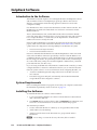
Click the desktop icon (or use Windows Explorer or the Start menu to navigate to
the IPI folder).
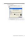
The program opens with the Getting Started pop-up screen displayed:
Use the scrollbar to find basic information about:
•
Log-in as User
•
Log-in as a HelpDesk Administrator
•
Change the Password
•
Set Up Intercom-equipped Extron Devices
To close the pop-up window, click OK.
IPI 100 and IPI 200 Series • HelpDesk Software
5-3
HelpDesk Software, cont’d
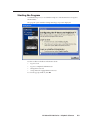
The main program window can now be seen:
The following section provides step by step procedures for some of the IP Intercom
system’s most common operations. For details about operations not shown here,
the user should refer to the HelpDesk help file, which can be accessed by clicking
Help in the Help menu or by pressing the F1 key from within the HelpDesk
program.
5-4
IPI 100 and IPI 200 Series • HelpDesk Software
Configuring the IP Intercom System
This section takes you through the step-by-step procedures for carrying out certain
basic tasks. The examples in this chapter specifically describe the IPI 204 devices
but apply to all IP Intercom models.
For information about more advanced setup and configuration, consult the
IP Intercom HelpDesk help file. Click the Help option in the Help menu or press F1
from within the HelpDesk program.
Basic Configuration
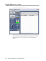
Using the Configuration Utility
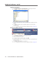
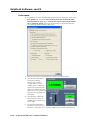
1. In the Tools menu, select Configuration Utility. The first time the utility is used
after opening the program a password pop-up box appears. Enter a password
in the pop-up box that opens. The default password is extron (all lower case
letters).
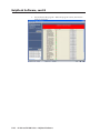
2. The Configuration Utility window opens:
3. Create a list of intercom devices. This can be done by
•
Importing a .gc2 or .gcz (Global Configurator) file
•
Entering IP addresses manually
•
Automatically by scanning the local subnet
Use the drop-down menu to select the appropriate option.
IPI 100 and IPI 200 Series • HelpDesk Software
5-5
HelpDesk Software, cont’d
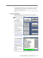
Importing a GC2/GCZ file
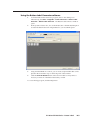
1. Select Import GC2/GCZ List (Recommended) from the drop-down menu.
2. Click Import. A Windows “Open” dialog box opens.
3. Navigate to the folder where you have saved the Global Configurator file and
select it.
4. Click Open. The Intercom List is updated using devices from the Global
Configurator file.
5. Go to “Configuring an IP device with the configuration utility” (see page 5-8).
Entering an IP address manually
1
2
3
4
1. Select Manually by IP Address from the drop-down menu.
2. Enter an IP address in the text box
3. The “Import” button is renamed “Add”. Click Add.
4. The new IP address appears on the Intercom list and you are prompted to give
the device a name.
5. Click Update Intercom List to save the device.
6. Go to “Configuring an IP device with the configuration utility” (see page 5-8).
5-6
IPI 100 and IPI 200 Series • HelpDesk Software
Scanning the local subnet
1. Select Automatic (Local Subnet Only) from the drop-down menu.
2. The “Add” button is renamed to “Scan”. Click Scan.
N The computer only scans the local subnet for available intercoms.
3. A Scan Progress dialog box opens, indicating the progress of the scan.
4. The scan detects only intercoms that are on the same local subnet and adds
them to the Configuration Utility’s Intercom List.
5. Click Update Intercom List to save the devices that have been added to the list.
6. Go to “Configuring an IP device with the configuration utility” (see page 5-8).
IPI 100 and IPI 200 Series • HelpDesk Software
5-7
HelpDesk Software, cont’d
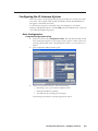
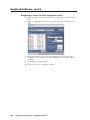
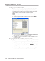
Configuring an IP device with the configuration utility
1. Open the configuration utility and select one of the IP devices in the Intercom
List.
2. When it is highlighted, its information is displayed in the Selected Intercom
pane:
3. In the Selected Intercom pane, the unit’s Administrator Password and the
IP addresses associated with each of the four buttons on the intercom can be
changed.
4. Click Apply to save the changes.
5. Click exit to close the Configuration Utility.
5-8
IPI 100 and IPI 200 Series • HelpDesk Software
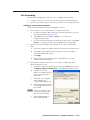
Talk mode
1. Select one of the IP devices
on the Active Intercom List in
the main screen.
2. Activate the Talk button by
clicking the Talk button and
holding down the mouse
button or by pressing and
holding down the keyboard
spacebar.
3. Speak into the headset’s
microphone. The Local
Mic VU meter will oscillate
in response to the audio
being picked up by the
microphone.
4. End talk mode by clicking
on the Talking button, or by
releasing the mouse or the
spacebar.
IPI 100 and IPI 200 Series • HelpDesk Software
5-9
HelpDesk Software, cont’d
Listen mode
1. Under the Tools menu open the Help Desk Preferences dialog box, click on the
User Options tab. Ensure the Play recurring alert tone at intercom panel
when panel mic is open option and Play alert tone at intercom panel when
mic is opened or closed options are checked (they are checked by default).
Close the Help Desk Preferences dialog box.
2. If necessary, select one of the IP devices on the Active Intercom List.
3. Activate the Listen button.
The intercom button
turns from low amber
to high amber color, two
audible signals of different
frequencies are heard at the
intercom to indicate that the
intercom’s mic is opened, and
the intercom’s green Mic On
LED lights.
4. Start speaking. While the
Listen button is active, an
audible signal is heard every
ten seconds.
5. Deselect the Listen button.
The button on the intercom
returns to a low amber color. A single audible signal is heard at the intercom.
5-10
IPI 100 and IPI 200 Series • HelpDesk Software
6. Press and hold the intercom button. It turns to a high amber color and the Mic
On LED lights green. On the PC monitor, the Listen button is activated, the
“Incoming Call Alert” indicator flashes, and two audible signals of different
frequencies are heard at the intercom.
7. Release the intercom button. It turns to a low amber color and the Mic On LED
turns off.
Group announcement
1. Decide which IP devices on the Active Intercom List you wish to group
together. Select each device one at a time and use the Group drop-down menu
to assign all of them to the same group.
N Each device on the Active
Intercom List can only
belong to one group.
2. Click the Group
Announcement button.
3. The Group Selection pane
becomes visible. Groups
that are available are listed
in black text; groups that are
not available are grayed out.
Select an available group or All
Intercoms.
4. The selected button turns
green and the intercom
devices belonging to that
group are highlighted in the
Active Intercom List.
5. Activate the Talk mode (see
step 2 of Talk Mode on page
5-9). When you have finished
talking inactivate the Talk
mode (see step 4 of Talk Mode on page 5-9).
or
Click the Play Sound Bite. A
list of available sound bites
appears. (For information
about managing the Sound
Bites list, see Loading a
pre‑recorded .wav file on
page 5-12) Select the sound
bite and click on the Play to
Intercom(s) button. The
button turns green and
the text is changed to Stop
Playing.
6. When the sound bite has
finished playing, click on the
Exit button.
7. Close the Group Selection pane by clicking on the Exit button.
IPI 100 and IPI 200 Series • HelpDesk Software
5-11
HelpDesk Software, cont’d
Loading a pre-recorded .wav file
The software allows you to load up to ten pre-recorded .wav files. The software
comes with a library of .wav files in the C:\Program Files\Extron\IPI\wav
folder. You can use these .wav files or record your own messages. For example,
non‑English speakers may find it easier to have the files in their native language.
After recording the .wav file, it should be saved in the same folder.
N The .wav file must be saved as 8 kHz, 16 bit, mono audio in PCM format.
To load a pre-recorded file:
1. Open the Configuration Utility. Under the Tools menu, select the Manage
Sound Bites option.
2. Click on the file button
and go to C:\Program Files\Extron\IPI\wav
folder. Select the .wav files that you wish to be available.
3. Click OK to close the Manage Sound Bites box and then click Exit to close the
Configuration Utility.
Changing the default .wav file for intercom events
Certain situations lead to default .wav files being played. It is possible to customize
those files.
1. Under the Tools menu open the Help Desk Preferences dialog box, click on the
Audio tab.
and navigate to
2. For each event, click on the corresponding file button
C:\Program Files\Extron\IPI\wav folder. Select the .wav files that you wish to
associate with that event.
3. As soon as a change is made, an OK button appears. When all the changes
have been made, click OK to close the Help Desk Preferences dialog box.
5-12
IPI 100 and IPI 200 Series • HelpDesk Software
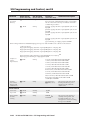
Call forwarding
The IP Intercom HelpDesk provides two ways of handling call forwarding:
1. A single PC, acting as a server, forwards calls to the next available help desk.
2. A peer-to-peer network allows calls to be forwarded to any available help desk.
Setting up a peer-to-peer network
All PCs must be running the IP Intercom HelpDesk software.
1. All PCs must have all available intercoms on their intercom list.
a.
On the first computer, add all intercoms to the intercom list by one of the
methods described on pages 4-5 to 4-7.
b. In the File menu, click on Save or Save As... to save the .xml
configuration project file.
c.
On each of the other help desks, in the file drop-down menu, select Load
Project. Load the project file saved in step 1b onto the help desk PC.
2. All intercoms must be linked to the IP address of one of the available help
desks:
a.
Open the Configuration Utility and select an intercom in the intercom list.
b. In the Button IP assignments pane, enter the server PC’s IP address or
select it from the dropdown list.
c.
Click Apply.
d. Repeat steps a-c until all intercoms have been linked to one of the
available help desk computers.
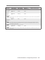
3. All help desk computers must have a list of all other available help desks,
which are added as follows:
a.
Open the Configuration Utility window and, in the Tools menu, click on
the Multiple HelpDesk Configuration... The HelpDesks window opens:
b. Add the name and IP
address of a HelpDesk in the
text boxes at the bottom of
the window.
c.
Click Add. The computer
will be added to the
Cooperating HelpDesks list.
d. Repeat steps b and c until all
cooperating HelpDesks have
been added.
N There is no automated way to
add multiple HelpDesks; they
must be added individually.
e.
When all HelpDesks have
been added, click OK.
IPI 100 and IPI 200 Series • HelpDesk Software
5-13
HelpDesk Software, cont’d
4. None of the PCs can be set to Server Mode:
a.
Under the Tools menu, click on Preferences. The Preferences box opens.
b. Click the Forwarding tab.
c.
Uncheck the Mode box. This box is left unchecked by default.
d. If necessary, shut down and restart the IP Intercom HelpDesk program.
Setting up one PC as a server
All PCs (the server and the help desks) must be running the IP Intercom HelpDesk
software.
1. The server PC and all HelpDesk PCs must have all available intercoms on their
intercom list.
a.
On the computer that has been designated the server, add all intercoms to
the server’s intercom list.
b. In the File menu, click on Save or Save As... to save the .xml
configuration project file.
c.
On each help desk computer, in the file drop-down menu, select Load
Project. Load the project file saved is step 1b onto the help desk PC.
2. All intercoms must be linked to the server’s IP address:
a.
Select an intercom in the intercom list.
b. In the Button IP assignments pane, enter the server PC’s IP address or
select it from the dropdown list.
c.
Click Apply.
d. Repeat steps a-c until all intercoms have been linked to the server.
3. The server PC must have a list of all client HelpDesks. The first name on the
list will be the server’s first choice HelpDesk. If the first PC is busy, the next
call will be passed to the second PC on the list. If all HelpDesks are busy, any
new incoming call will hear a pre-recorded .wav file. This pre-recorded .wav
file will usually inform the caller that all help desks are busy and suggest
calling back later.
These are added as described in steps 3a to 3e on page 5-13.
4. All HelpDesks must be linked to the Server PC:
a.
On each HelpDesk PC, open the HelpDesks window as described in step
3a on the previous page.
b. Add the name and IP address of the server PC in the text boxes at the
bottom of the window.
c.
Click Add.
d. Click OK.
5-14
IPI 100 and IPI 200 Series • HelpDesk Software
5. The server PC must be set to Server Mode:
a.
Under the Tools menu, click on Preferences. The Preferences box opens.
b. Click the Forwarding tab.
c.
Check the Mode box.
d. An OK button appears. Click on the OK button.
IPI 100 and IPI 200 Series • HelpDesk Software
5-15
HelpDesk Software, cont’d
e.
5-16
Exit and restart the program. When the program restarts, the window
will have changed:
IPI 100 and IPI 200 Series • HelpDesk Software
IPI 100 and IPI 200 Series
A
Appendix A
Specifications, Part Numbers,
Accessories
Specifications — IPI 100 Series
Included Parts (IPI 100 Series)
Accessories (IPI 100 Series)
Specifications — IPI 200 Series
Included Parts (IPI 200 Series)
Accessories (IPI 200 Series)
Specifications, Part Numbers, Accessories
Specifications — IPI 100 Series
Audio— IPI 101, IPI 104 and MLC 226 IP
Speaker������������������������������������������� 1.4" (35.6 mm), 1-way, indoor
Frequency response
Line level output (MLC)�� 20 Hz to 3.3 kHz, ±1 dB
Speaker output (IPI)���������� 300 Hz to 3.3 kHz, -10 dB
Nominal sensitivity/IPI speaker output level
80 dB SPL, 300 mW, 3' (1 m)
Processing
Audio format��������������������� PCM, µ-law companded
Sampling rate��������������������� 8 kHz
Sample size������������������������� 16 bit, µ-law companded to 8 bit
Audio latency�������������������� <100 ms
Audio input— IPI
Number/signal type��������������������� 1 mono, via integrated electret microphone
Microphone gain��������������������������� -30 dB to 0 dB, adjustable in 2 dB steps
N
0 dBu = 0.775 Vrms, 0 dBV = 1 Vrms, 0 dBV ≈ 2 dBu
Audio output
Number/signal type��������������������� 2 mono: 1 via MLC 226 IP, 1 via IPI speaker
Line level (MLC)���������������������������� -10 dBV (316 mVrms), unbalanced (via 3.5 mm captive screw connector,
2 pole)
Amplified speaker (IPI)���������������� 300 mW, continuous, 1% THD
Ethernet control interface via MLC 226 IP
Ethernet control/communications port
1 female RJ-45 connector
Ethernet data rate/transport bandwidth
80 kbps
Communications type������������������ Half duplex
Protocol������������������������������������������� IP (control), TCP (control), UDP (port 3121, audio), Telnet
Program control (via MLC)��������� Extron control/configuration program for Windows®
Extron Simple Instruction Set (SIS™)
Microsoft® Internet Explorer, Telnet
General
Power���������������������������������������������� Supplied by an MLC 226 IP
Power input requirements����������� +12 VDC, <100 mA
Distance between MLC 226 IP and an IPI
100' (30.5 m), maximum
Connection type (IPI–MLC)�������� RJ-45 jacks with CAT 5, CAT 5e, or CAT 6 cable
Temperature/humidity���������������� Storage: -40 to +158 °F (-40 to +70 °C) / 10% to 90%, noncondensing
Operating: +32 to +122 °F (0 to +50 °C) / 10% to 90%, noncondensing
Cooling������������������������������������������� Convection
Mounting
Rack mount������������������������ Yes, with optional faceplate
Furniture mount���������������� Also furniture- and wall-mountable with optional faceplate or in an
MLC 226 IP AAP faceplate
Enclosure type������������������������������� Metal faceplate
A-2
IPI 100 and IPI 200 Series • Specifications, Part Numbers, Accessories
Enclosure dimensions
Board/device��������������������� 2.7" H x 2.6" W x 0.9" D (6.9 cm H x 6.6 cm W x 2.3 cm D)
(Depth excludes buttons and switch. Allow at least 2.1" (5.3 cm) depth in the
wall or furniture.)
Product weight������������������������������ 0.2 lb (0.1 kg)
Shipping weight���������������������������� 1 lbs (1 kg)
Vibration����������������������������������������� ISTA 1A in carton (International Safe Transit Association)
Regulatory compliance
Safety����������������������������������� CE, c-UL, UL
Compliances����������������������� CE, C-tick, FCC Class A, ICES, VCCI
MTBF����������������������������������������������� 30,000 hours
Warranty����������������������������������������� 3 years parts and labor
N
All nominal levels are at ±10%.
N
Specifications are subject to change without notice.
Included Parts (IPI 100 Series)
These items are included in each order for an IPI intercom module:
Included parts
Replacement
part number
IPI 104 AAP (black, white)
70-502-0x
IPI 101 AAP (black, white)
70-501-0x
RJ-45 interconnection cable (12" CAT 5e)
26-632-01
Button labels
33-1344-01
Tweeker (small screwdriver)
IPI 100 Series Installation Instructions
Accessories (IPI 100 Series)
Accessories
Part number
MLC 226 IP (black, white, RAL9010
white, or without faceplate)
60-600-0x
MLC 226 IP AAP
(black, white, RAL9010 white)
60-600-1x
MLC 226 IP L
(black, white, RAL9010 white)
60-600-3x
9-pin D female to 2.5 mm TRS
configuration cable
70-335-01
MPA 152
60-844-01
MPA 181 T
60-747-01
Text and Icon labels
Button cap and diffuser kit (set of 3
button cap assemblies)
33-1762-01,
33‑1763‑02
70-352-01
IPI 100 and IPI 200 Series • Specifications, Part Numbers, Accessories
A-3
Specifications, Part Numbers, Accessories, cont’d
Specifications — IPI 200 Series
Audio
Speaker������������������������������������������� 1.4" (35.6 mm), 1-way, indoor
Frequency response
Line level output��������������� 20 Hz to 3.3 kHz, ±1 dB
Speaker output������������������ 300 Hz to 3.3 kHz, -10 dB
Nominal sensitivity/IPI speaker output level
80 dB SPL, 300 mW, 3' (1 m)
Processing
Audio format��������������������� PCM, µ-law companded
Sampling rate��������������������� 8 kHz
Sample size������������������������� 16 bit, µ-law companded to 8 bit
Audio latency�������������������� <100 ms
Audio input
Number/signal type��������������������� 1 mono, via integrated electret microphone
Microphone gain��������������������������� -30 dB to 0 dB, adjustable in 2 dB steps
N
0 dBu = 0.775 Vrms, 0 dBV = 1 Vrms, 0 dBV ≈ 2 dBu
Audio output
Number/signal type��������������������� 2 mono: 1 via audio output port, 1 via IPI speaker
Line level output��������������������������� -10 dBV (316 mVrms), balanced/unbalanced (via 3.5 mm captive screw
connector, 3 pole)
Amplified speaker output������������ 300 mW, continuous, 1% THD
Ethernet control interface
Ethernet control/communications port
1 female RJ-45 connector
Ethernet data rate/transport bandwidth
80 kbps
Communications type������������������ Half duplex
Ethernet protocol��������������������������� IP (control), TCP (control), UDP (port 3121, audio), Telnet
Default settings������������������������������ Link speed and duplex level: autodetected
IP address = 192.168.254.254
Subnet mask = 255.255.0.0
Default gateway = 0.0.0.0
DHCP = off
Program control����������������������������� Extron control/configuration program for Windows®
Extron Simple Instruction Set (SIS™)
Microsoft® Internet Explorer ver. 6 or higher, Telnet
Control — relay
Number/type�������������������������������� 1 momentary or latching (configurable)
Connector��������������������������������������� (1) 3.5 mm captive screw connector, 2 pole, C (common) and NO (normally
open) for configurable relay output
Contact rating�������������������������������� 24 V, 1 A
A-4
IPI 100 and IPI 200 Series • Specifications, Part Numbers, Accessories
General
External power supply����������������� 100 VAC to 240 VAC, 50-60 Hz, external; to 12 VDC, 2 A, regulated
Power input requirements����������� +12 VDC, 0.25 A
Temperature/humidity���������������� Storage: -40 to +158 °F (-40 to +70 °C) / 10% to 90%, noncondensing
Operating: +32 to +122 °F (0 to +50 °C) / 10% to 90%, noncondensing
Cooling������������������������������������������� Convection, no vents
Mounting
Rack mount������������������������ Yes, with optional faceplate and rack mounting kit
Furniture mount���������������� Yes, furniture- and wall-mountable with optional faceplate and mounting
kits
Enclosure type������������������������������� Metal faceplate
Enclosure dimensions
IPI 201, IPI 204 faceplate�� 4.5" H x 4.6" W x 0.1" D (11.4 cm H x 11.7 cm W x 0.3 cm D)
(fits some 2 gang boxes)
IPI 201 AAP, IPI 204 AAP faceplate
2.8" H x 3.5" W x 0.1" D (7.1 cm H x 8.9 cm W x 0.3 cm D)
(four space AAP plate)
Device��������������������������������� 2.8" H x 2.7" W x 1.85" D
(6.9 cm H x 6.6 cm W x 4.9 cm D)
(Depth excludes buttons. Allow at least 2.25" (5.5 cm) depth in the wall/
furniture.)
INTERCOM
POWER
C NO
RELAY
MIC ON
AUDIO OUT
LAN
PUSH TO TALK
RESET
HELP
DESK
ROOM
101
LAB
ADMIN
OFFICE
1
2
3
4
CONFIG
Extron
IPI 204 Rear
Left Side
IPI 204
Front
IPI 100 and IPI 200 Series • Specifications, Part Numbers, Accessories
A-5
Specifications, Part Numbers, Accessories, cont’d
4.6”
3.5”
2.7"
2.7"
2.8”
4.5”
2.8"
1.85”
2.8"
IPI 204 AAP
Rear
1.85”
IPI 204
Rear
Product weight������������������������������ 0.5 lbs (0.2 kg)
Shipping weight���������������������������� 3 lbs (1 kg)
Vibration����������������������������������������� ISTA 1A in carton (International Safe Transit Association)
Regulatory compliance
Safety����������������������������������� CE, c-UL, UL
EMI/EMC�������������������������� CE, C-tick, FCC Class A, ICES, VCCI
MTBF����������������������������������������������� 30,000 hours
Warranty����������������������������������������� 3 years parts and labor
N
All nominal levels are at ±10%.
N
Specifications are subject to change without notice.
A-6
IPI 100 and IPI 200 Series • Specifications, Part Numbers, Accessories
Included Parts (IPI 200 Series)
These items are included in each order for an IPI intercom module:
Included parts
Replacement
part number
IPI 201 AAP (black, white)
60-809-1x
IPI 201 2-gang (black, white)
60-809-0x
IPI 204 AAP (black, white)
60-810-1x
IPI 204 2-gang (black, white)
60-810-0x
12 V, 1 A power supply
70-055-01
Button labels
33-1344-01
IPI 200 Series Installation Instructions
Accessories (IPI 200 Series)
Amplifiers, cable, miscellany
Part number
9-pin D female to 2.5 mm TRS
configuration cable
70-335-01
MPA 152
60-844-01
MPA 181 T
60-747-01
Text and Icon labels
Button cap and diffuser kit (set of 3
button cap assemblies)
33-1762-01,
33‑1763‑02
70-352-01
IPI 100 and IPI 200 Series • Specifications, Part Numbers, Accessories
A-7
Specifications, Part Numbers, Accessories, cont’d
A-8
IPI 100 and IPI 200 Series • Specifications, Part Numbers, Accessories
IPI 100 and IPI 200 Series
B
Appendix B
SIS Programming and Control
Introduction to SIS
Symbols used in this manual
Error messages
Command/Response table for SIS commands
SIS Programming and Control
The Extron MediaLink IP Intercom 201 and 204 modules can be remotely set up
and controlled via a host computer or other device (such as a control system) by
using the Extron Simple Instruction Set (SIS™) commands, accessed via RS-232 or an
Ethernet LAN connection.
N The following SIS commands are for use with the IPI 201 and 201 models
only. Refer to the MLC 226 IP Series User’s Manual for IPI 101/104 series SIS
command and control information.
IPI RS-232 protocol:
•
38400 baud
•
8 data bits
•
1 stop bit
•
no parity
•
no flow control
N The configuration port requires 38400 baud communication. This is a higher
speed than many other Extron products use. If using HyperTerminal or a
similar application, make sure the PC or control system connected to these ports
is set for 38400 baud.
LAN port defaults:
•
IP address: 192.168.254.254
•
gateway’s IP address: 0.0.0.0
•
subnet mask: 255.255.0.0
•
DHCP: off
N The IP Intercom (IPI) must be configured before use.
Host-to-IPI Communications
SIS commands consist of one or more characters per field. No special characters
are required to begin or end a command sequence. When the IPI determines that
a command is valid, it executes the command and sends a response to the host
device. All responses from the IPI to the host end with a carriage return and a line
feed (CR/LF = ]), which signals the end of the response character string. A string
is one or more characters.
IPI-initiated Messages
If you are communicating with the IPI via RS-232 or via a verbose Telnet connection
when a local event such as a front panel selection or adjustment takes place, the IPI
responds by sending a message to the host. No response is required from the host. The IPI-initiated messages are listed here (underlined).
(c)Copyright 2007, Extron Electronics, IPI 201 V1.00, 60-809-00 ]
Mon Day, DD Mon YYYY HH:MM:SS
(c)Copyright 2007, Extron Electronics, IPI 204, V1.00, 60-810-00 ]
Mon Day, DD Mon YYYY HH:MM:SS
Vx.xx is the firmware version number.
The IPI sends the boot and copyright messages under the following circumstances:
•
B-2
If the IPI is off and an RS-232 connection is already set up (the PC is cabled
to the IPI 204 series and a serial terminal emulation program such as
HyperTerminal is open), the connected unit sends these messages via RS-232
when it is first powered on.
IPI 100 and IPI 200 Series • SIS Programming and Control
•
If the IPI is on, it sends the boot and copyright messages when you first open
a Telnet connection to the IPI. You can see the day of the week, date, and time
if the IPI is connected via Telnet, but not via RS-232. If you are using a Telnet
connection, the copyright message, date, and time are followed by a password
prompt.
Additional messages may be sent by the IPI in response to front panel selections
and volume adjustments and when scripts are executed during scheduled events.
Password information
The “]Password:” prompt requires a password (administrator level or user level)
followed by a carriage return. The prompt is repeated if the correct password is not
entered.
If the correct password is entered, the unit responds with “]Login Administrator ]”
or “]Login User]”, depending on the password entered. If passwords are the same
for both administrator and user, the unit will default to administrator privileges.
Error responses
When the IPI receives a valid SIS command, it executes the command and sends a
response to the host device. If the IPI is unable to execute the command because
the command is invalid or it contains invalid parameters, it returns an error
response to the host.
The error response codes and their descriptions are as follows:
E12 – Invalid port number
E13 – Invalid value (the number is out of range/too large)
E14 – Not valid for this configuration
E17 – System timed out
E22 – Busy
E24 – Privilege violation
E26 – Maximum number of connections has been exceeded
E27 – Invalid event number
E28 – Bad filename or file not found
E30 – Hardware failure (followed by colon and descriptor number) (This is an unsolicited response.)
E31 – Attempt to break port pass-through when not set
Error response references
The following superscripted numbers are used within the command descriptions
on the following pages to identify commands that may respond as shown:
= Commands that give an E14 (not valid for this configuration) response if the
unit’s current configuration doesn’t support that command.
14
22
= Commands that yield an E22 (busy) response.
= Commands that give an E24 (privilege violation) response if you are not logged
in at the administrator level.
24
27
= Commands that may yield an E27 (invalid event number) response.
28
= Commands that may give an E28 (file not found) response.
IPI 100 and IPI 200 Series • SIS Programming and Control
B-3
SIS Programming and Control, cont’d
Commands and Reponses
Using the command/response table
The IPI 201/204 Series intercom can be controlled via either a Telnet (port 23)
or RS‑232 connection using ASCII commands. Or it can be controlled via a Web
browser (port 80) connection using URL-encoded commands. The ASCII and URL
commands listed in the table starting on page B‑8 perform the same functions, but
they are encoded differently to accommodate the requirements of each port (Telnet
or browser).
The ASCII to hexadecimal (HEX) conversion table shown below is for use with the
command/response tables.
ASCII to HEX Conversion Table
Space
.
The command/response table lists valid ASCII (for Telnet or RS‑232) command
codes, the corresponding URL (uniform resource locator) encoded (for Web
browsers) command codes, the IPI’s responses to the host, and a description of the
command’s function or the results of executing the command.
B-4
•
Upper and lower case characters may be used interchangeably in the command
field unless otherwise specified.
•
Commands may be sent back-to-back without spaces (for example, 11S0X4Q).
•
Numbers can be entered with leading zeroes, as 1, 2, or 3 digits.
•
There are a few differences in how to enter the commands depending on
whether you are using Telnet or a Web browser. oo
When using these commands through a Web browser, the URL reference
is used to shorten the examples. “URL” refers to the full URL of the
intercom and Web page reference including all path information (e.g.,
http://192.168.100.10/myform.htm).
oo
To send any of the commands using a Web browser you must prefix them
with the full URL followed by ?cmd=.
IPI 100 and IPI 200 Series • SIS Programming and Control
oo
For control via a Web browser, all non-alphanumeric characters must be
represented as the hexadecimal equivalent, %xx, where xx represents the
two-character hex byte. A comma (,), for example, would be represented
as %2C. Characters such as %, +, and the space character ( ) must be encoded as
hex bytes, or they will be misinterpreted by the IPI.
oo
Some characters differ depending on the method you use to send the
commands:
Telnet
Web Browser
Escape (hex 1B)
W (must not be hex encoded)
Carriage return (hex 0D)
Pipe character (|)
(must not be hex encoded)
N With Telnet you can use either an “Escape” (E) command or a “W” command,
and the carriage return or the pipe character. With the Web browser, you are
required to use a “W” command and the pipe character.
In either method, {Data} = data that will be directed to a specified port and must be
hex encoded if non-alphanumeric.
N If you make adjustments (changes to volume, etc.), whether via the front panel or
via RS-232 or IP communication, it will take 1 minute 40 seconds (100 seconds)
for the data in the IPI 200 series’ RAM to be saved to flash memory.
Symbol definitions
] = CR/LF (carriage return/line feed) (hex 0D 0A)
} = Carriage return (no line feed, hex 0D)
(use the pipe character, | , instead for URL-encoded commands)
• =
Space character
| = Pipe (vertical bar) character
E = Escape key (hex 1B)
(use W instead of Esc for Web browsers)
N For Web encoding only: data will be directed to the specified port and
must be encoded (URL encoding) if it is non-alphanumeric. Change any
non‑alphanumeric character (%, +, |, }, etc.) within the data section into
the corresponding hexadecimal equivalent, %xx, where xx represents the
two-character hex byte. For example, a space (hex: 20) would be encoded as
%20 (hex: 25 32 30) and a plus sign (hex: 2B) would be encoded as %2B or
hex 25 32 42.
X# = Greenwich Mean Time (GMT) offset value (‑12.00 to +14.00) represents the
time difference in hours and minutes (+/-hh:mm) relative to Greenwich,
England. The leading zero is optional. For example, 5:30 = 05:30. Do not use
a plus (+) sign if the GMT offset is positive.
X% = On/off status
0 = off / disable
1 = on /enable
X1! = Version (typically listed to two decimal places, e.g., x.xx)
X1@ = IPI 200 series’ name. The name is a text string of up to 24 characters drawn
from the alphabet (A-Z), digits (0-9), and minus sign/
hyphen (-). No blank or space characters are permitted as part of a name. No distinction is made between upper and lower case. The first character
must be a letter. The last character must not be a minus sign/hyphen.
IPI 100 and IPI 200 Series • SIS Programming and Control
B-5
SIS Programming and Control, cont’d
X1# = Local date and time format
Set format (MM/DD/YY-HH:MM:SS).
Example: 01/18/05-10:54:00.
Read format (day of week, date month year HH:MM:SS).
Example: Tue, 18 Jan 2005 18:19:33.
X1$ = IP address or subnet mask (xxx.xxx.xxx.xxx). Leading zeros in each of four
fields are optional in setting values, and they are suppressed in returned
values.
IPI’s default address: 192.168.254.254
Default broadcast address: 255.255.255.255.
X1* = Hardware (MAC) address (xx-xx-xx-xx-xx-xx) (00-05-A6-xx-xx-xx)
X2@ = Verbose/response mode status:
0 = clear/none, default for Telnet connections; responses are not echoed to
the host
1 = verbose mode is on, default for RS-232 host control; responses are echoed
to the host and displayed to the user
2 = send tagged responses for queries
3 = verbose mode is on and tagged responses are sent for queries
N If tagged responses are enabled, all read commands return the constant string +
data, the same as for setting a value. For example, for E CN }, the response
is Ipn•X1@ ] rather than just the data.
X3# = Password (minimum length = 4 characters, maximum length = 12 characters,
no special characters are allowed)
N A user password cannot be assigned if no administrator password exists; the E14
error code will be returned. If the administrator password is cleared, then the
user password is also removed.
X3$ = Daylight saving time
0 = Daylight Saving Time off/ignore
1 = Daylight Saving Time on (USA/Canada)
2 = Daylight Saving Time on (Europe)
3 = Daylight Saving Time on (Brazil)
X4! = Password to display on screen (response to password query or set). When
the MLC connects to a host device via RS-232, the password (X3#), itself, is the
response. When the connection is via IP, X4! is 4 asterisks (****) if a password
has been assigned, or it is an empty field ( ) if a password hasn’t been
assigned.
X4( = Default name: a combination of the model name and the last 3 pairs of the
IPI 200 series’ MAC address
X5@ = Connection’s security level
11 = user
12 = administrator
X6# = Pulse time in 20 ms per count. If this parameter is missing or = 0, then pulse
length = default = 25 = 500 ms. 1 = 20 ms (minimum pulse time) to 65535 =
1310700 ms (maximum pulse time).
B-6
IPI 100 and IPI 200 Series • SIS Programming and Control
X6$ = Broadcast repetition interval in seconds (0 to 255 [4.25 minutes], default = 0 =
off).
X7! = Hardware (MAC) address: 4 most-significant hex nibbles converted into
single 16-bit decimal number.
X7@ = Hardware (MAC) address: 8 least significant hex nibbles converted into
single 32-bit decimal number.
N This could be as large as 10 digits.
X20^ = Voltage (in volts)
X20& =Temperature in degrees Celsius (the response is 3 digits including leading
zeros)
X20( = Front panel lockout (executive mode) status
0 = off/unlocked (default)
1 = on, disable/lock the front panel
IPI 100 and IPI 200 Series • SIS Programming and Control
B-7
SIS Programming and Control, cont’d
Command/response table for SIS commands
Command
ASCII (Telnet)
URL Encoded
Response
Additional Description
Force relay on
1*1O
1 %2A1 O
Rly 1 *1]
Turn relay on.
Force relay off
1*0O
1 %2A0 O
Rly 1 *0]
Turn relay off.
Toggle relay
1*2O
1%2A2O
Rly 1* X%]
Toggle relay on/off. X% = 1 (on) or 0 (off).
Pulse relay
1*3*X6# O
1%2A3%2AX6# O
Rly 1 * X%]
Rly 1 * X%]
Set relay’s pulse time (X6#) in
20 ms increments from 1 (20 ms,
minimum) to 65535 (1310700 ms,
maximum).
Default pulse length is 25 = 500 ms.
(host to intercom)
(host to intercom)
(intercom to host)
Relay functions
N If the verbose mode is enabled, there are two responses from the unit because the relay is pulsed. During a pulse, the relay is
toggled to its opposite state and then back to the original state.
View the relay
state
1O
1O
Rly 1 * X%]
Front panel security lockout modes (executive modes)
Off24
0X
0X
Exe 0]
Executive mode is off.
On24
1X
1X
Exe 1]
Executive mode is on.
View lockout
mode status
X
X
X20(]
X20( = Front panel lockout
(executive mode) status
0 = off/unlocked (default)
1 = on, disable/lock the front panel
X
X
0]
Executive mode is off.
Example:
Status commands
View all
voltage and
temperature
status
11S
11S
shows responses to commands
12S•13S•14S•15S•16S•20S ]
View +12 V
P/S voltage
12S
12S
+X20^]
View +5 V IR
receiver port
voltage
13S
13S
+X20^]
View +3.3 V
IP Link/FPGA
voltage
14S
14S
+X20^]
View +1.5 V
FPGA voltage
15S
15S
+X20^]
View internal
temp. status
20S
20S
X20&]
B-8
IPI 100 and IPI 200 Series • SIS Programming and Control
X20^ = Voltage (in volts)
X20& =Temperature in degrees
Celsius (the response is 3 digits
including leading zeros)
Command
ASCII (Telnet)
(host to intercom)
URL Encoded
(host to intercom)
Response
(intercom to host)
Additional Description
Firmware version, part number & information requests
N In a query response, an asterisk (*) after the version number indicates the version that is currently used.
A question mark (? or ?.??) indicates that the factory default firmware is the only firmware loaded in the IPI.
A carat (^) indicates the version of firmware that should be running, but, since a mode 1 reset was performed, the factory default
firmware version is loaded and running instead.
An exclamation point (!) indicates that the firmware is corrupted.
Q or 1Q
Q or 1Q
X1! c
Example:
1Q
1Q
1.01]
or Ver01*1.01
Query verbose
firmware
version
information
0Q
0Q
X1! X1! X1! ]
X1! = Version (typically listed to
responses to
commands
2Q•3Q•4Q ]
two decimal places, e.g., x.xx)
Shows bootstrap, factory-installed,
and current versions of firmware.
Example:
0Q
0Q
1.03•1.00*(1.18-IPI 201/IPI 204 - Thu, 20 Jan 2005 09:41:47
GMT)•1.01*(1.31-IPI 201/IPI 204 -Tue, 14 Jun 2005 00:54:58
GMT)]
2Q
2Q
X1! ]
Example:
2Q
2Q
1.03 ]
Query factory
firmware
version
3Q
3Q
X1! ]
Example:
3Q
3Q
1.00*(1.18-IPI 201/IPI 204-Thu, 20 Jan 2005 09:41:47 GMT) ]
4Q
4Q
X1!]
Query
firmware
version
number
Query
bootstrap
firmware
version
Query
updated
firmware
version
or Ver01*X1! ]
or Ver02*X1! ]
or Ver03*X1! ]
or Ver04*X1!]
Show the IPI’s firmware version
(X1!) to two decimal places. This
query yields the number of the
currently running version of the
user-updatable firmware
The bootstrap firmware is not userreplaceable, but you may need this
information during troubleshooting.
X1! = (kernel version–model
description–date time of upload)
Factory-installed firmware is
different from the bootstrap
firmware, but it is also not userreplaceable. This firmware was
installed at the factory; it is the
version the controller reverts to after
a mode 1 reset (see chpt. 2).
X1! = (kernel version–model
description–date time of upload)
Use this command to find out which
version of the firmware, if any, was
uploaded into the controller after it
left the factory
4Q
4Q
1.00*(1.64-IPI 201/IPI 204 -Mon, 28 Feb 2005 23:16:55 GMT)]
Query FPGA
version
32Q
32Q
X1! ]
Show the field-programmable gate
array (FPGA) firmware version to
two decimal places (x.xx).
Request the
IPI’s part
number
N
N
60-809-0n ] or
60-810-0n ] or
Pno60-809-1n ] or
Pno60-810-1n ]
See page A-7 for 200 Series part
numbers.
Example:
IPI 100 and IPI 200 Series • SIS Programming and Control
B-9
SIS Programming and Control, cont’d
Command
ASCII (Telnet)
URL Encoded
Response
Request the
model name
1I
1I
IPI 201 ] or
IPI 204 ]
Request
the model
description
2I
2I
One-Button IP
Intercom] or
Four-Button IP
Intercom]
Request
system
memory usage
3I
3I
Show amount of memory used and
total available memory for system
operations.
Request user
memory usage
4I
4I
Show amount of user memory used
and total available user memory.
Query IPI
module
32I
32I
IPI201] or
IPI204]
201 = IPI 201 AAP or 2-gang
204 = IPI 204 AAP or 2-gang.
(host to intercom)
(host to intercom)
(intercom to host)
Additional Description
IP setup commands
Set the unit
name24
E X1@ CN}
W X1@ CN|
Ipn• X1@ ]
Change the IPI’s name to one of
your choosing (X1@), such as “execboardroom-ctrl”. The name consists
of up to 24 alphanumeric characters
(and the minus sign). The first
character must be a letter, the last
character cannot be a minus sign
(hyphen). Case does not matter.
Set unit name
to factory
default24
E •CN}
W%20CN|
Ipn•X4( ]
X4( = the factory default name,
Read the unit
name
E CN}
WCN|
X1@ ]
X4( ]
Set date/
time24
E X1# CT}
W X1# CT|
Ipt• X1# ]
Read date/
time
E CT}
W CT|
X1# ]
Set GMT
offset24
E X# CZ}
W X# CZ|
Ipz X# ]
Read GMT
offset
E CZ}
WCZ|
X# ]
Set daylight
saving time24
E X3$ CX}
WX3$ CX|
Ipx X3$ ]
X3$ = which is a combination of the model
name and the last 3 pairs of hex
numbers in the controller’s MAC
address (e.g., IPI-104-IP-00- 02-3D).
or
X1# = Local date and time in the
format: MM/DD/YY-HH:MM:SS.
Example: 09/07/06-10:54:00.
X# = Greenwich Mean Time (GMT)
offset value (‑12.00 to +14.00)
represents the difference in hours
and minutes relative to Greenwich,
UK. The leading zero is optional.
Do not use a plus (+) sign.
Daylight saving time
0 = Daylight Saving Time off/ignore
1 = Daylight Saving Time on (USA/Canada)
2 = Daylight Saving Time on (Europe)
3 = Daylight Saving Time on (Brazil)
B-10
X1@ = user-defined name.
X4( = factory default name.
IPI 100 and IPI 200 Series • SIS Programming and Control
Command
ASCII (Telnet)
URL Encoded
Response
Additional Description
Read daylight
saving time
E CX}
W CX|
X3$ ]
X3$ See note at bottom of page B-10
Set DHCP on24
E 1 DH}
W1DH|
Idh 1 ]
Set DHCP off24
E 0 DH}
W0DH|
Idh 0 ]
Setting DHCP to off also resets
the unit’s IP address to the factory
default (192.168.254.254).
View DHCP
mode
E DH}
WDH|
X% ]
X% = 0 (off) or 1 (on).
Set IP
address24
E X1$ CI}
W X1$ CI|
Ipi• X1$ ]
X1$ = IP address (xxx.xxx.xxx.xxx).
Leading zeros in each of the four
fields are optional in setting values.
Read IP
address
E CI}
W CI|
X1$ ]
Leading zeros in each of the four
fields are suppressed.
Read
hardware
address
(MAC)
E CH}
WCH|
X1* ] or
Iph•X1* ]
X1* = hardware (MAC) address (xxxx-xx-xx-xx-xx).
Set subnet
mask24
E X1$ CS}
W X1$ CS|
Ips• X1$ ]
X1$ = IP address or subnet mask
(xxx.xxx.xxx.xxx).
Read subnet
mask
E CS}
WCS|
X1$]
Leading zeros suppressed.
Set gateway IP
address24
E X1$ CG}
W X1$ CG|
Ipg• X1$ ]
X1$ = IP address or subnet mask
(xxx.xxx.xxx.xxx). Leading zeros are
optional.
Read gateway
IP address
E CG}
WCG|
X1$ ]
Set verbose
response
mode on/off24
E X2@ CV}
W X2@ CV|
Vrb X2@ ]
(host to intercom)
(host to intercom)
(intercom to host)
X2@ = verbose mode status:
0 = clear/none, default for Telnet
connections; responses are not
echoed to the host
1 = verbose mode is on, default for
RS-232 host control; responses are
echoed to the host and displayed to
the user
2 = send tagged responses for
queries
3 = verbose mode is on and tagged
responses are sent for queries.
N If tagged responses are enabled, all read commands return the constant string + data, the same as for setting a value.
For example, for E CN }, the response is Ipn• X1@ ] rather than just the data.
N Verbose mode is a communication mode in which the device responds with more information than it usually would—more than the
device, itself, requires. For example, the controller can send out unsolicited information (such as notice of a volume or input change
or a change in some other setting). That is an example of a verbose (wordy) relationship between the controller and a connected
device. Verbose mode creates more network traffic than usual, which can slow down network performance.
Verbose mode is usually enabled for troubleshooting and disabled for daily use.
• For a direct RS-232 connection, the controller is set for verbose mode by default. • When the IPI is connected via Ethernet, verbose mode is disabled (by default) in order to reduce the amount of communication
traffic on the network. If you want to use the verbose mode with a controller connected via Ethernet, this mode must be set to “on”
each time you reconnect to the controller.
IPI 100 and IPI 200 Series • SIS Programming and Control
B-11
SIS Programming and Control, cont’d
Command
ASCII (Telnet)
URL Encoded
Response
Read verbose
mode status
E CV }
WCV|
X2@ ]
Set the
broadcast
interval24
E X6$,X1$ EB }
W X6$%2C X1$ EB|
Bmd X6$,X1$ ]
X6$ = Broadcast repetition interval
in seconds (0 to 255 [4.25 minutes],
default = 0 = off).
X1$ = subnet address (xxx.xxx.xxx.
xxx). Default broadcast address:
255.255.255.255.
Set broadcast
interval
to default
address24
E X6$ EB }
W X6$ EB|
Bmd X6$,X1$ ]
X1$ = Default broadcast subnet
address: 255.255.255.255.
Clear
broadcast
interval24
E 0 EB }
W 0 EB|
Bmd X6$,X1$ ]
X6$ = Broadcast repetition interval
set to 0 (off).
X1$ = Default broadcast subnet
address: 255.255.255.255.
View
broadcast
interval
E EB }
W EB|
X6$,X1$ ]
Set broadcast
port
E {port#}*X7! , X7@
View
broadcast port
and MAC
E PB}
(host to intercom)
(host to intercom)
PB}
(intercom to host)
Additional Description
Bpt {port#}*X1* ]
W{port#}*X7! , X7@ PB|
WPB|
{port#}*X1* ]
N {port#} = UDP outgoing port, X7! * X7@ = MAC address for UDP unicast transmissions.
N Changes to the PB command become effective in kernel versions 1.53 or higher.
Get
connections
listing
E CC }
WCC |
verbose modes 0/1: {# of
connections} ]
verbose modes 0/1: Icc {# of
connections} ]
Password and security settings
Set
administrator
password24
E X3# CA }
W X3# CA |
Ipa• X4! ]
Clear
administrator
password24
E • CA }
W%20 CA ]
Ipa• ]
Clear/remove all passwords
(administrator and user).
N A user password cannot be assigned if an administrator password does not exist. Also, if the administrator password is cleared,
the user password is also cleared.
Read
administrator
password
E CA }
WCA|
X4! ]
X2@ = verbose mode status:
0 = clear/none, default for Telnet connections; responses are not echoed to the host
1 = verbose mode is on, default for RS-232 host control; responses are echoed to the host and displayed to the user
2 = send tagged responses for queries
3 = verbose mode is on and tagged responses are sent for queries.
X3# = Administrator password has 4 to 12 alphanumeric characters and is case sensitive. Special characters (spaces, symbols) not
allowed.
X4! = Password displayed on screen. When the IPI connects to a host device via RS-232, the password is shown. When the connection
is via IP, 4 asterisks are shown (or an empty field if no password has been assigned).
B-12
IPI 100 and IPI 200 Series • SIS Programming and Control
Command
Set user
password14, 24
ASCII (Telnet)
URL Encoded
Response
E X3# CU }
W X3# CU|
Ipu•X4! ]
(host to intercom)
(host to intercom)
(intercom to host)
Additional Description
X3# = user password
X4! = Password displayed
on
screen.
N A user password cannot be assigned if an administrator password does not exist. Also, if the administrator password is cleared, the
user password is also cleared.
Clear user
password24
E • CU }
W%20CU|
Ipu• ]
Read user
password
E CU }
WCU|
X4! ]
Read
connection’s
security level
E CK }
WCK |
X5@ ] or
Pvl X5@ ]
This clears the user password only.
For X5@
11 = user
12 = administrator
Remapping port designations
For security reasons the network administrator may wish to assign new/different port numbers to the controller’s Telnet, Web
browser, and direct access ports or to disable one or more ports. Typically Telnet uses port 23, Web access is via port 80 (HTTP),
and direct access is via port 2001.
Do not set two or more ports to the same port number. Setting two ports to the same number could cause networking
C
conflicts and will also result in an E13 (invalid parameter) error.
N If you remap a port, you must set the port number to 1024 or higher, unless you reset the port to the default number or disable the
port by setting it to 0.
Set Telnet
port24
E {port#}MT }
W{port#}MT|
Pmt {port#} ]
Set a Telnet port number that does
not conflict with any other ports.
Reset Telnet
port 24
E 23MT }
W23MT|
Pmt 00023 ]
Reset the Telnet port to port 23.
Disable Telnet
port24
E 0MT }
W0MT|
Pmt 00000 ]
Disables the port.
Read Telnet
port
E MT }
WMT|
{port#} ]
Set HTTP
port24
E {port#}MH }
W{port#}MH|
Pmh {port#} ]
Set a HTTP port number that does
not conflict with any other ports.
Reset HTTP
port24
E 80MH }
W80MH|
Pmh 00080 ]
This resets the HTTP port to port 80.
Disable HTTP
port24
E 0MH }
W0MH|
Pmh 00000 ]
Disables the port.
Read the Web
port map
E MH }
WMH|
{port#} ]
Set Direct
Access port24
E {port#}MD }
W{port#}MD|
Pmd {port#} ]
Set a direct access port number that
does not conflict with any other
ports.
Reset Direct
Access port24
E 2001MD }
W2001MD|
Pmd 02001 ]
This resets the direct access port to
port 2001.
Disable Direct
Access port24
E 0MD }
W0MD|
Pmd 00000 ]
Disables the port.
Read Direct
Access port
E MD }
WMD|
{port#} ]
IPI 100 and IPI 200 Series • SIS Programming and Control
B-13
SIS Programming and Control, cont’d
Command
ASCII (Telnet)
(host to intercom)
URL Encoded
(host to intercom)
Response
(intercom to host)
Additional Description
Directory commands
E path/directory/ CJ }
Change to
or create a
directory
W path %2F directory %2F CJ|
Dir•path/directory/]
The directory’s name must be composed of alphanumeric characters and may include the minus sign (hyphen, -) and the colon (:). The first character must be a letter. Case does not matter. No blank or space characters are permitted in the name. Include the full
path, not just the name of the directory. Nonalphanumeric characters are not permitted in the Web browser.
N A directory does not fully exist until a file has been copied into that path. Also, the IPI operates differently from PC operating
systems: files stored in and directories created in the IPI may have the same names.
Example 1:
E majordirectory/subdirectory/next-level/ CJ}
W majordirectory %2F subdirectory %2F next-level %2F CJ |
Dir•majordirectory/subdirectory/next-level/ ]
Example 2:
E custompages/HTMLfiles/ CJ}
W custompages %2F HTMLfiles %2F CJ|
Dir•custompages/HTMLfiles/ ]
Example 3:
E oak/CJ}
W oak %2F CJ|
Dir• oak ]
In example 1, the path is majordirectory/subdirectory/. The command created or moved to a directory called next-level.
In example 2, a directory called HTMLfiles was created inside the custompages directory.
In example 3, the user moved to a directory called oak.
Change back
to the root
directory
E/CJ}
W %2F CJ|
Dir•/]
Go up one
directory level
E.. CJ}
W %2E %2E CJ|
Dir•path/directory/ ]
View the
current
directory
E CJ}
W CJ|
path/directory/ ]
Moves to the system’s root directory.
N The current directory is determined on a per-connection basis. At the beginning of each IP connection/session, the current
directory is selected as the root directory.
N Directory = A text string drawn from the alphabet (A~Z), digits (0~9), minus sign/hyphen (-), plus sign (+), or colon (:). No
blank or space characters are permitted as part of a name. No distinction is made between upper and lower case. The first character
must be an alpha character. A directory does not truly exist until a file has been copied into that path. Unlike various PC operating
systems, a File and Directory on the Extron product are allowed to have the same name. The current directoy is a per-connection
setting. It begins at the root for each new IP session.
Stream Files via Telnet or RS–232
Load a file
to user flash
memory
E + UF filesize, filename}
Upl]
Retrieve file
from user
flash memory
E filename SF}
responds with
4‑bytes of file-size +
raw undprocessed
data in file}
N If there is insufficient space on a box to store the sent file, response will be “Fld] “ instead of “Upl]” to denote failure.
N Updating firmware can be done by loading an .S19 file with this command. If the box determines that the .S19 file is not intended
for this product, the “Upl]” response is followed by an “Fwm]” response (Firmware mismatch).
B-14
IPI 100 and IPI 200 Series • SIS Programming and Control
Command
ASCII (Telnet)
(host to intercom)
URL Encoded
(host to intercom)
Response
(intercom to host)
Additional Description
Stream Files via Port 80
Load file to
user flash
memory
Use a POST on port 80 followed by the
delimited data to be written to the flash file
memory.
Retreive file
from user
flash memory
Send a page GET on port 80 followed by:
WSF| e.g. http://192.168.254.254/mypage.
html?cmd=WSF|
Responds with raw unprocessed data in file
File handling commands
Erase usersupplied Web
page and
files24,28
E filename EF}
W filename EF|
Del • filename ]
Erase current
directory and
its files24,28
E/EF}
W %2F EF|
Ddl]
Erase current
directory
and subdirectories24,28
E//EF}
W %2F %2F EF|
Ddl]
IPI 100 and IPI 200 Series • SIS Programming and Control
B-15
SIS Programming and Control, cont’d
Command
List files from
the current
directory
ASCII (Telnet)
URL Encoded
Response
E
DF}
WDS|
Retrieve a list of files stored in the controller. Each line of
the response lists a different filename and its corresponding
file size. The last line of the response indicates how much
available file space there is.
E
DF}
W DF|
[filename 1]• [day, date time of upload] GMT • [file size 1 in
bytes]]
[filename 2]• [day, date time of upload] GMT • [file size 2 in
bytes]]
[filename 3]• [day, date time of upload] GMT • [file size 3 in
bytes]]
…
[filename n]• [day, date time of upload] GMT • [file size n in
bytes]]
[space remaining (to 7-digits)] • Bytes Left ]]
(host to intercom)
(host to intercom)
(intercom to host)
Additional Description
When working with the IPI’s embedded Web pages, the response visible in HTML source code follows this structure:
var file=new Array();
file[1]=“[filename 1],[day, date time1 of upload] GMT,[file size 1 in bytes]”; ]
file[2]=“[filename 2],[day, date time2 of upload] GMT,[file size 2 in bytes]”; ]
file[3]=“[filename 3],[day, date time3 of upload] GMT,[file size 3 in bytes]”; ]
…
file[n]=“[filename n],[day, date timen of upload] GMT,[file size n in bytes]”; ]
file[n+1]=”[space remaining (to 7-digits)],Bytes Left;]
Example (via
Telnet or
HyperTerminal)
E DF}
W DF|
4.evt Tue, 01 Mar 2005 02:03:07 GMT 42233]
1.eml Tue, 01 Mar 2005 02:03:34 GMT 200]
2.eml Tue, 01 Mar 2005 02:03:34 GMT 300]
2.eir Tue, 01 Mar 2005 02:03:34 GMT 1683]
6.evt Tue, 01 Mar 2005 02:03:36 GMT 17956]
4.eir Tue, 01 Mar 2005 02:03:47 GMT 6849]
IPImain.sc Tue, 01 Mar 2005 02:03:52 GMT 8515]
0.evt Tue, 01 Mar 2005 02:03:56 GMT 34413]
99.eml Tue, 01 Mar 2005 02:04:19 GMT 178]
buttons.xml Tue, 01 Mar 2005 02:04:19 GMT 17214]
IPI.cfg Wed, 16 Mar 2005 21:34:45 GMT 7188]
6568448 Bytes Left ]]
List files
from current
directory and
subdirectories
E LF}
WLF|
(See responses to
E DF}, above.)
Start events
E 1AE}
W1AE|
Ego]
Stop events
E 0AE}
W0AE|
Est]
Query number
of events
running
E AE}
WAE|
The response is the same except
that the path/directory prece filenames for files within the
subdirectories.
Event Control
B-16
#####] or
Enm #####]
IPI 100 and IPI 200 Series • SIS Programming and Control
The response is the quantity of
currently running events, and
it includes leading zeros. For
example, if two events are running,
the response is 00002].
Command
ASCII (Telnet)
(host to intercom)
URL Encoded
Response
(host to intercom)
(intercom to host)
Additional Description
Reset (zap)/Erase Commands
Erase all files
from flash
memory
E ZFFF}
WZFFF|
Zpf]
Reset all
devices
settings to
factory presets
E ZXXX}
WZXXX|
Zpx]
N Excludes IP settings such as IP address, subnet mask, gatewate IP address and IP Security-level table. User files in flash memory
will not be deleted.
Reset all
device settings
and delete
files
E ZY}
WZY|
Zpy]
N This is an absolute system reset but excludes IP settings such as IP address, subnet mask, gateway IP address, unit name,
DHCP setting and port mapping (Telnet/Web/direct access) in order to preserve communicaiton with the device. This reset is
recommended after a firmware update.
N The ZY command appears n kernel versions 1.45 or higher.
Absolute
system reset
E ZQQQ}
WZQQQ|
Zpq]
N (Mode 5 reset) Resets alls device settings, including IP settings, to factory default. Also rerases flash memory. Firmware version
remains the same.
IPI 100 and IPI 200 Series • SIS Programming and Control
B-17
SIS Programming and Control, cont’d
B-18
IPI 100 and IPI 200 Series • SIS Programming and Control
IPI 100 and IPI 200 Series
C
Appendix C
Mounting
Mounting the IPI 100 Series
Mounting the IPI 200 Series
Mounting
Mounting the IPI 100 Series
The IPI intercom and any other adapter plates must be attached to a device
faceplate or AAP wall plate and cabled before the device or wall plate is installed in
a wall or furniture. The screws needed for installing the IPI are built into its front
panel.
1. Before cables are attached, insert the IPI’s screws through the holes in the
device’s faceplate or AAP mounting frame. Secure the intercom module to
the faceplate/wall plate with the provided captive washers and #4-40 nuts, as
shown below:
#4-40 Nut w/ Captive
Washer
(included)
TO
AU E
G
IMA
R
TO
EC
OJ
PR
R
VC
1
4
F
OF
TE
MU
ON
E
M
LU
VO
P
PTO
3
6
C
2
5
PC
C
DOM
CA
LA
ML
6
22
IP
P
AA
CO
ER
INT
EL
V
LE
M
HIGH
MED
W
LO
K
AL
OT
HT
US
FIG
P
N
CO
ON
MIC
X
AU O
E
VID
D
DV
IR
B
LA
SE
4
Y
RIT
CU
LP
HE K
S
DE
MIN
AD ICE
F
OF
IPI
10
4
3
2
1
Ex
tro
n
Extron
MLC 226 IP AAP
Extron
IPI 104 AAP
Intercom
MediaLink Controller
2. Connect each IPI to an MLC via the RJ-45 intercom ports on both devices using
the included cable. If a longer cable is required, use a standard CAT 5, CAT
5e, or CAT 6 straight through network cable. See “IPI Rear Panel Features and
Cabling” on page 2-2.
3. Mount the AAP mounting frame or other device to the wall, furniture, or rack
panel. Follow any special mounting instructions that came with that device.
C-2
IPI 100 and IPI 200 Series • Mounting
Mounting the IPI 200 Series
The IPI 201 and IPI 204 intercoms must be attached to a device faceplate or AAP
wall plate and cabled before the device or wall plate is installed in a wall or
furniture. Unlike the IPI 100 Series intercoms, the IPI 200 AAP Series intercoms are
secured by attaching a clamp bracket to the back of the intercom after it has been
inserted through the front of the AAP plate.
Extron
IPI 204 AAP
Intercom
(rear view)
Clamp Bracket
(included)
1. Before cables are attached, insert the IPI through the front of the device’s
faceplate or AAP mounting frame. Secure the IPI to the faceplate/wall plate by
attaching the provided clamp bracket.
2. Connect cables to the IPI. See “IPI Rear Panel Features and Cabling” on
page 2-2.
3. Mount the AAP mounting frame or other device to the wall, furniture, or rack
panel. Follow any special mounting instructions that came with that device.
IPI 100 and IPI 200 Series • Mounting
C-3
Mounting, cont’d
C-4
IPI 100 and IPI 200 Series • Mounting
IPI 100 and IPI 200 Series
D
Appendix D
Button Labels
Installing or Replacing Button Labels
Button Labels
Installing or Replacing Button Labels
Printed labels are included with the IPI 100 Series and IPI 200 Series. In addition,
users can write on blank labels, purchase additional sheets of printed button labels
from Extron (see page A-3 or A-7) or print their own customized button labels with
the Button Label Generator program. Replacement button caps are also available
for purchase.
Button Label Generator software
The Button Label Generator software creates labels that you can place in
the translucent covers above the buttons. You can create labels with names,
alphanumeric characters, or color graphics for easy and intuitive input and output
selection.
Installing the Button-Label Generator software
The Extron Button Label Generator is available on the Extron Web site,
www.extron.com, under the Download tab. Click the Software link, and download
and install the program by following the on screen instructions.
N The Button Label Generator software is also included on the Extron Software
Products disk that accompanies the IP Intercom unit.
By default, the Windows installation creates a C:\Program Files\Extron\
ButtonLabelGenerator directory and places the Button Label Generator icon into a
group or folder named “Extron Electronics”. A shortcut icon can also be placed on
the PC desktop.
D-2
IPI 100 and IPI 200 Series • Button Labels
Using the Button-Label Generator software
1.
To run the Button-Label Generator program, click on the desktop icon. Alternatively, click Start > Programs > Extron Electronics > Button Label
Generator > Button Label Generator. The Button-Label Generator window
opens.
2.
In the Systems selection box, choose the IPI 101/201 or the IPI 104/204 option
to match the button label size and quantities for your TouchLink panel:
3.
Using standard Windows controls, you can create and print labels that can be
placed in the clear button caps on the front panel of the switcher.
4.
Click the Clear All Buttons button and create new labels as many times as
necessary to make all of the button labels that you need.
To access the help program, click the Help menu.
IPI 100 and IPI 200 Series • Button Labels
D-3
Button Labels
Installing Button Labels
The button assembly consists of a clear lens cap, the label and a white diffuser. To
remove a button assembly and replace a label:
1. Use a small flat-blade screwdriver to gently
pry the button assembly away from its
plunger/base.
MIC
L
VE HIGH
LE
OM
RC
TE
IN
ON
K
SH
PU
B
LA
CU
SE
LP
HE K
S
DE
L
TA
TO
Y
RIT
D
ME
W
LO
MIN
AD ICE
F
OF
4
IPI
4
10
3
2
1
2. Locate the small corner notch on the lens cap and slide
the screwdriver between the lens cap and the
diffuser, as shown in the figure at right.
Using a rotating motion of the
screwdriver (see the figure at
right), carefully pry the two
pieces apart.
3. Replace the label with
the new button label.
Base
TE
XT
Diffuser
Clear Lens
4. Press the lens cap and
diffuser together and
reinstall the button
assembly into its
plunger/base.
5. Repeat steps 1 through
4 for each button you
plan to re-label.
D-4
Plunger
IPI 100 and IPI 200 Series • Button Labels
Button Label
Pry the two
pieces apart.
Notch
Separating the twopiece button here at
the corner.
Extron Warranty
Extron Electronics warrants this product against defects in materials and workmanship for a period
of three years from the date of purchase. In the event of malfunction during the warranty period
attributable directly to faulty workmanship and/or materials, Extron Electronics will, at its option,
repair or replace said products or components, to whatever extent it shall deem necessary to restore
said product to proper operating condition, provided that it is returned within the warranty period,
with proof of purchase and description of malfunction to:
USA, Canada, South America,
and Central America:
Extron Electronics
1001 East Ball Road
Anaheim, CA 92805
U.S.A.
Japan: Extron Electronics, Japan
Kyodo Building, 16 Ichibancho
Chiyoda-ku, Tokyo 102-0082
Japan
Europe, Africa, and the Middle East:
Extron Europe
Hanzeboulevard 10
3825 PH Amersfoort
The Netherlands
China:
Extron China
686 Ronghua Road
Songjiang District
Shanghai 201611
China
Asia:
Extron Asia
135 Joo Seng Road, #04-01
PM Industrial Bldg.
Singapore 368363
Singapore
Middle East:
Extron Middle East
Dubai Airport Free Zone
F12, PO Box 293666
United Arab Emirates, Dubai
This Limited Warranty does not apply if the fault has been caused by misuse, improper handling care,
electrical or mechanical abuse, abnormal operating conditions or non-Extron authorized modification
to the product.
If it has been determined that the product is defective, please call Extron and ask for an Applications
Engineer at (714) 491-1500 (USA), 31.33.453.4040 (Europe), 65.383.4400 (Asia), or 81.3.3511.7655 (Japan)
to receive an RA# (Return Authorization number). This will begin the repair process as quickly as
possible.
Units must be returned insured, with shipping charges prepaid. If not insured, you assume the risk of
loss or damage during shipment. Returned units must include the serial number and a description of
the problem, as well as the name of the person to contact in case there are any questions.
Extron Electronics makes no further warranties either expressed or implied with respect to the
product and its quality, performance, merchantability, or fitness for any particular use. In no event
will Extron Electronics be liable for direct, indirect, or consequential damages resulting from any
defect in this product even if Extron Electronics has been advised of such damage.
Please note that laws vary from state to state and country to country, and that some provisions of this
warranty may not apply to you.
Quick Installation Checklist
Determine which rooms will have IP Intercoms and HelpDesk PCs and where,
in each room, they will be located. Ensure there is a network connection for each
intercom and each HelpDesk PC.
For the IPI 100 Series models
Connect the IPI to the MLC 226 IP controller, using the included 12 inch (30.5 cm)
network cable (see page 2-2).
Cable the MLC 226 IP to other devices:
• Connect the LAN port to the local network, using a standard network cable with
an RJ-45 connector.
•
If desired, cable the rear panel audio connector for local audio output (see
page 2-2).
•
Cable other devices (control modules, SCP, and/or IR emitters) to the MLC
as needed (for more information, see the MLC 226 IP User’s Manual, which is
available on the Extron website (www.extron.com).
Install the IPI 100 unit and the MLC 226 IP into the wall box(es) or furniture (see
page C-2).
Ensure the HelpDesk PC(s) is connected to the network and power it on.
Configure the MLC(s) as described in the MLC 226 IP User’s Manual and the Global
Configurator Help File, which are available on the Extron website
(www.extron.com).
For the IPI 200 Series models
Connect the LAN port to the local network, using a standard network cable, with an
RJ-45 connector (see page 2-3).
Connect power, and, if required, contact relay and local audio output, using the rear
panel captive screw connectors (see page 2-3).
Mount each IPI 200 into furniture, an AAP wallplate, mounting bracket for 2-gang
wallplates, or device faceplate. The AAP versions must be secured by attaching a
clamp bracket to the back of the intercom after it has been inserted through the front
of the AAP plate (see page C-3).
Ensure the HelpDesk PC(s) is connected to the network and power it on.
For all models
Install the Extron IP Intercom HelpDesk software, which is on the disk that shipped
with the unit and is also available for download from the Extron website
(www.extron.com).
Use the IP Intercom HelpDesk software to configure all intercom units in the system
(see chapter 5). Full instructions can be found in the software’s Help File.
When the front panel button(s) light amber, the unit is correctly installed and
configured. If the button(s) light red the unit has not been correctly configured and you
should check the IPI 100 Series and IPI 200 Series User’s Manual or the software’s Help
File.
Extron USA - West
Headquarters
+800.633.9876
Inside USA / Canada Only
+1.714.491.1500
+1.714.491.1517 FAX
Extron USA - East
Extron Europe
Extron Asia
Extron Japan
Extron China
Extron Middle East
+800.633.9876
+800.3987.6673
+800.7339.8766
+81.3.3511.7655
+81.3.3511.7656 FAX
+400.883.1568
+971.4.2991800
+971.4.2991880 FAX
+1.919.863.1794
+1.919.863.1797 FAX
+31.33.453.4040
+31.33.453.4050 FAX
+65.6383.4400
+65.6383.4664 FAX
Inside USA / Canada Only
Inside Europe Only
Inside Asia Only
© 2009 Extron Electronics. All rights reserved.
Inside China Only
+86.21.3760.1568
+86.21.3760.1566 FAX