1
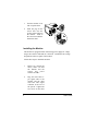
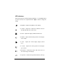
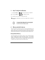
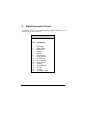
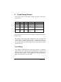
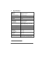
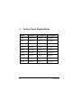
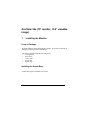
AcerView 54e (15” monitor, 13.6” viewable
image)
1.
Installing the Monitor
Product Package
Open the shipping carton and check the contents. If any item are missing or
damaged, contact your dealer immediately.
The package should include the following items:
Ÿ
Color monitor
Ÿ
Swivel base
Ÿ
User‘s guide
Ÿ
Power cord
Ÿ
Signal cable
Installing the Swivel Base
Follow these steps to install the swivel base:
User’s Guide
1
1.
Turn the monitor on its
side or upside-down.
2.
Insert the pegs on the
swivel base into the
cavities at the bottom of
the monitor. Push on
the swivel base until the
latch clicks shut.
Installing the Monitor
This monitor is equipped with an autosensing power supply for voltage
ranges 100-120VAC/200-240VAC, 60/50 Hz. Confirm the line voltage
designation on the rear panel of the monitor.
Follow these steps to install the monitor:
1.
Before you connect the
cables, make sure that
the monitor and the
system
unit
power
switches are Off.
2.
Plug one end of the 15pin signal cable to the
monitor and the other
end to the video signal
connector at the rear of
the system. Tighten the
two screws on the cable
2
User’s Guide
connector.
3.
.
Connect
cable.
User’s Guide
the
power
3
2.
Control Functions
The monitor digital control functions are located on the front panel. They
are shown in the figure below and described in the following paragraphs.
1. Power Switch
7. Vertical Size
2. Adjust
8. Horizontal Phase
3. Select
9. Horizontal Size
4. Trapezoid
10. Contrast
5. Pincushion
11. Brightness
6. Vertical Center
4
User’s Guide
LED indicators
Each LED represents a different display adjustment. Use the Select button
to choose the item to be adjusted and the Adjust button to change the
setting.
. Brightness: Adjusts the brightness of the display.
. Contrast: Adjusts the contrast, the difference between
the light and dark areas on the screen.
. H-Size: Adjusts the display width (horizontal size).
. H-Phase: Adjusts the horizontal position of the display
(left or right).
. V-Size:
Adjusts the vertical display height (vertical
size).
. V-Center:
Adjusts the vertical position of the display
(up or down).
. Pincushion:
Controls the concave and convex curve at
the vertical edges of the display.
. Trapezoid: Controls the trapezoidal distortion on the top
User’s Guide
5
or bottom of the display
The LED indicator goes off after 20 seconds of inactivity. If any settings
have changed, the monitor automatically saves the new settings.
Select
button to cycle through the adjustment options to
Press the
or
choose H-Phase, H-Size, V-Center, V-Size, Contrast, Brightness,
Trapezoid, and Pincushion. The corresponding LED indicator lights up
when selected. Use the Adjust buttons to change the settings.
Adjust
Adjusts the settings for H-Phase, H-Size, V-Center, V-Size, Contrast,
Brightness, Trapezoid, and Pincushion. Use the Select button to choose the
item to be adjusted and press
or
to change the setting.
Power Switch
Turns the monitor on (I) or off (O). The power switch is located at the base
of the monitor. The LED indicates the ON/OFF status of the unit.
Reset
Adjusts all settings to factory defaults.
6
User’s Guide
3.
How To Adjust the Monitor
Press the Select key (
Press the Adjust key (
or
or
) to choose the item to be adjusted.
) to change the setting.
Repeat the above procedure to change other items.
The monitor automatically saves the new settings after 20 seconds of
inactivity.
In the event that display distortion is incurred due
to magnetic field interference, face the monitor to
the east for the best display quality.
4.
Microcontroller Features
The microcontroller automatically detects the video board installed in your
system. When you turn on the monitor, the microcontroller first checks the
display mode memory stored in the user setting area of the video board, and
then the factory presetting area. It then adjusts to the proper display mode.
Display Modes Memory
The microcontroller has the memory capacity to store 32 different display
modes, including timing formats and display settings. This memory
capacity is divided into two parts: the user setting area and the factory
presetting area. The former can store 20 display modes. The latter can store
12 display modes and has already stored 9 display modes.
User’s Guide
7
User Setting Area
The user setting area on the microcontroller maintains in its memory the last
20 display modes set by the user. You can change the settings, or add a
nonstandard mode. The microcontroller always detects and displays the last
mode stored in the user setting area first when the monitor is turned on.
Factory Presetting Area
There are 9 preferred display modes preset in the microcontroller. These
display modes are preset at the factory and include the most popular display
modes currently available (see the Specifications section).
The
microcontroller searches for a proper display mode in this area if it fails to
find a proper display mode in the user setting area.
8
User’s Guide
5.
Signal Connector Pinouts
To connect VGA, 8514A or IBM-compatible graphics adapters, use a 15pin mini D-type male connector.
15-Pin Mini D-Type Male Connector
User’s Guide
Pin
Assignment
1
2
3
4
5
6
7
8
9
10
11
12
13
14
15
Red Video
Green Video
Blue Video
Ground
Ground
Red Ground
Green Ground
Blue Ground
No Connection
Sync Ground
Ground
Serial Data I/O
H. Sync
V. Sync
Serial Clock Input
9
6.
Power Saving Feature
This monitor’s power saving feature complies with these VESA power
saving modes:
Mode
H.Sync
V.Sync
LED
Power Consumption
Normal
On
On
Green
90 w
Stand-by
Off
On
Amber
<15 w
Suspend
On
Off
Amber
<15 w
Off
Off
Off
Amber
Blinking
<5 w
The monitor uses the H.Sync and V.Sync signals to determine the operation
mode to enter.
The monitor power-saving feature automatically turns off H.Sync and
V.Sync if there is no input from the system for a certain period of time. To
use this feature, you need a green PC that is compliant with the VESA
power saving feature or a software utility to detect system input such as the
keyboard or mouse.
Time Settings
Time settings are adjusted from the system unit by software. To fulfill the
requirements in the NUTEK specification 803299/94 the total time from
indicated inactivity to Power Saving Position A2 (VESA Off) must not be
set to more than 70 minutes. We recommend you switch off the monitor
when you do not intend to use it for awhile.
10
User’s Guide
7.
*
Specifications
Picture tube
Size:
Dot pitch:
Surface/transmission:
15-inch (38 cm) diagonal
0.28 mm
Non-glare/semi-tinted
Maximum viewable size*
13.6-inch (34.6 cm) diagonal
Video input
15-pin, D-sub connector, analog (positive)
Bandwidth
65 MHz
Display area
270 mm x 202 mm (H x V)
Power supply (Universal)
Input voltage:
Consumption:
90V~264V / 47~63 Hz
90 watts maximum
External controls
Power switch, brightness, contrast, adjust,
select, pincushion, V-size, V-center, H-size,
H-phase, trapezoid, reset
Horizontal frequency
30 ~ 54 KHz
Vertical frequency
50 ~ 110 Hz
Dimensions (with stand)
376 mm x 367 mm x 385 mm (W x H x D)
Weight
16 kg (35 lb)
Ambient temperature
Operating:
Nonoperating:
5°C ~ 40°C
0°C ~ 60°C
Humidity
Operating:
Storage:
20% ~ 90%
10% ~ 90%
X-Radiation
DHHS, PTB
Regulatory Compliance
FCC-B, UL, CSA, BZT-B
CE, TÜV, D.N.S.F, VCCI, MPRII (optional)
For VGA and most VESA display modes
User’s Guide
11
8.
12
Factory Preset Display Modes
Mode
Resolution
V. Frequency
H. Frequency
VGA
640 x 400
70 Hz
31.47 KHz
VGA
640 x 480
60 Hz
31.47 KHz
VGA
640 x 480
72 Hz
37.86 KHz
VGA
640 x 480
75 Hz
37.5 KHz
SVGA
800 x 600
60 Hz
37.88 KHz
SVGA
800 x 600
75 Hz
46.88 KHz
SVGA
800 x 600
72 Hz
48.09 KHz
Ultra VGA
1024 x 768
60 Hz
48.37 KHz
SVGA
800 x 600
85 Hz
53.67 KHz
User’s Guide